1
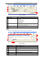
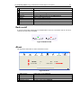
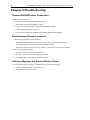
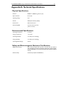
AT-WNP300N
IEEE802.11b/g/n 1T2R Wireless
Fast PCI adapter
User Manual
PN613-001218 Rev. A
2
AT-WNP300N - IEEE802.11b/g/n 1T2R Wireless Fast PCI adapter - User Manual
Copyright © 2009 Allied Telesis, Inc.
All rights reserved. No part of this publication may be reproduced without prior written permission from Allied
Telesis, Inc.
Microsoft and Internet Explorer are registered trademarks of Microsoft Corporation. Netscape Navigator is a
registered trademark of Netscape Communications Corporation. All other product names, company names, logos
or other designations mentioned herein are trademarks or registered trademarks of their respective owners.
Allied Telesis, Inc. reserves the right to make changes in specifications and other information contained in this
document without prior written notice. The information provided herein is subject to change without notice. In no
event shall Allied Telesis, Inc. be liable for any incidental, special, indirect, or consequential damages whatsoever,
including but not limited to lost profits, arising out of or related to this manual or the information contained herein,
even if Allied Telesis, Inc. has been advised of, known, or should have known, the possibility of such damages.
AT-WNP300N IEEE802.11b/g/n 1T2R Wireless Fast PCI adapter User Manual
SAFETY NOTICE
Do not change any component.
Only qualified technicians are allowed to service the equipment.
Observe safety precautions to avoid electric shock
LIMITATION OF LIABILITY AND DAMAGES
THE PRODUCT AND THE SOFTWARES WITHIN ARE PROVIDED "AS IS," BASIS. THE
MANUFACTURER AND MANUFACTURER’S RESELLERS (COLLECTIVELY REFERRED TO AS
“THE SELLERS”) DISCLAIM ALL WARRANTIES, EXPRESS, IMPLIED OR STATUTORY,
INCLUDING
WITHOUT
LIMITATION
THE
IMPLIED
WARRANTIES
OF
NON-INFRINGEMENT, MERCHANTABILITY OR FITNESS FOR A PARTICULAR PURPOSE,
OR ANY WARRANTIES ARISING FROM COURSE OF DEALING, COURSE OF
PERFORMANCE, OR USAGE OF TRADE. IN NO EVENT WILL THE SELLERS BE LIABLE FOR
DAMAGES OR LOSS, INCLUDING BUT NOT LIMITED TO DIRECT, INDIRECT, SPECIAL
WILFUL, PUNITIVE, INCIDENTAL, EXEMPLARY, OR CONSEQUENTIAL, DAMAGES,
DAMAGES FOR LOSS OF BUSINESS PROFITS, OR DAMAGES FOR LOSS OF BUSINESS OF
ANY CUSTOMER OR ANY THIRD PARTY ARISING OUT OF THE USE OR THE INABILITY
TO USE THE PRODUCT OR THE SOFTWARES, INCLUDING BUT NOT LIMITED TO THOSE
RESULTING FROM DEFECTS IN THE PRODUCT OR SOFTWARE OR DOCUMENTATION,
OR LOSS OR INACCURACY OF DATA OF ANY KIND, WHETHER BASED ON CONTRACT,
TORT OR ANY OTHER LEGAL THEORY, EVEN IF THE PARTIES HAVE BEEN ADVISED OF
THE POSSIBILITY OF SUCH DAMAGES. THE ENTIRE RISK AS TO THE RESULTS AND
PERFORMANCE OF THE PRODUCT OR ITS SOFTWARE IS ASSUMED BY CUSTOMER.
BECAUSE SOME STATES DO NOT ALLOW THE EXCLUSION OR LIMITATION OF LIABILITY
FOR DAMAGES, THE ABOVE LIMITATION MAY NOT APPLY TO THE PARTIES. IN NO
EVENT WILL THE SELLERS’ TOTAL CUMULATIVE LIABILITY OF EACH AND EVERY KIND IN
RELATION TO THE PRODUCT OR ITS SOFTWARE EXCEED THE AMOUNT PAID BY
CUSTOMER FOR THE PRODUCT.
3
4
AT-WNP300N - IEEE802.11b/g/n 1T2R Wireless Fast PCI adapter - User Manual
ELECTRICAL SAFETY AND EMISSIONS STANDARDS
This product meets the following standards.
U.S. Federal Communications Commission Interference Statement
This equipment has been tested and found to comply with the limits for a Class B digital device, pursuant to Part 15 of the FCC Rules.
These limits are designed to provide reasonable protection against harmful interference in a residential installation. This equipment
generates, uses and can radiate radio frequency energy and, if not installed and used in accordance with the instructions, may cause
harmful interference to radio communications. However, there is no guarantee that interference will not occur in a particular
installation. If this equipment does cause harmful interference to radio or television reception, which can be determined by turning the
equipment off and on, the user is encouraged to try to correct the interference by one of the following measures:
Reorient or relocate the receiving antenna.
Increase the separation between the equipment and receiver.
Connect the equipment into an outlet on a circuit different from that to which the receiver is connected.
Consult the dealer or an experienced radio/TV technician for help.
FCC Caution: Any changes or modifications not expressly approved by the party responsible for compliance could void the user's
authority to operate this equipment.
This device complies with Part 15 of the FCC Rules. Operation is subject to the following two conditions: (1) This device may not cause
harmful interference, and (2) this device must accept any interference received, including interference that may cause undesired
operation.
Radiation Exposure Statement: This equipment complies with FCC radiation exposure limits set forth for an
uncontrolled environment. This equipment should be installed and operated with minimum distance 20cm between the radiator & your
body.
This transmitter must not be co-located or operating in conjunction with any other antenna or transmitter.
The availability of some specific channels and/or operational frequency bands are country dependent and are firmware programmed at
the factory to match the intended destination. The firmware setting is not accessible by the end user.
CE Marking Warning
This device complies with the essential requirements of the R&TTE Directive 1999/5/EC. The following test methods have been applied
in order to prove presumption of conformity with the essential requirements of the R&TTE Directive 1999/5/EC:
EN 60950-1: 2006
Safety of Information Technology Equipment
EN 50385: 2002
Product standard to demonstrate the compliance of radio base stations and fixed terminal stations for wireless telecommunication
systems with the basic restrictions or the reference levels related to human exposure to radio frequency electromagnetic fields
(110MHz - 40 GHz) - General public
EN 300 328 V1.7.1 (2006-10)
Electromagnetic compatibility and Radio spectrum Matters (ERM); Wideband transmission systems; Data transmission equipment
operating in the 2,4 GHz ISM band and using wide band modulation techniques; Harmonized EN covering essential requirements under
article 3.2 of the R&TTE Directive
EN 301 489-1 V1.8.1 (2008-04)
Electromagnetic compatibility and Radio Spectrum Matters (ERM); ElectroMagnetic Compatibility (EMC) standard for radio equipment
and services; Part 1: Common technical requirements
EN 301 489-17 V1.3.2 (2008-04)
Electromagnetic compatibility and Radio spectrum Matters (ERM); ElectroMagnetic Compatibility (EMC) standard for radio equipment
and services; Part 17: Specific conditions for 2,4 GHz wideband transmission systems.
This device is a 2.4 GHz wideband transmission system (transceiver), intended for use in all EU member states and EFTA countries,
except in France and Italy where restrictive use applies.
In Italy the end-user should apply for a license at the national spectrum authorities in order to obtain authorization to use the device
for setting up outdoor radio links and/or for supplying public access to telecommunications and/or network services.
This device may not be used for setting up outdoor radio links in France and in some areas the RF output power may be limited to 10
mW EIRP in the frequency range of 2454 – 2483.5 MHz. For detailed information the end-user should contact the national spectrum
authority in France.
AT-WNP300N IEEE802.11b/g/n 1T2R Wireless Fast PCI adapter User Manual
5
CONTENTS
LIMITATION OF LIABILITY AND DAMAGES .................................................................................................. 1
Preface ................................................................................................................................................................................... 9
Purpose of This Guide ............................................................................................................................................... 9
How This Guide is Organized.................................................................................................................................. 9
Document Conventions ............................................................................................................................................ 9
Contacting Allied Telesis ................................................................................................................................................10
Online Support...........................................................................................................................................................10
Email and Telephone Support ................................................................................................................................10
Warranty .....................................................................................................................................................................10
Where to Find Web-based Guides ......................................................................................................................10
Returning Products ...................................................................................................................................................10
Sales or Corporate Information ............................................................................................................................10
Firmware & Software Updates...............................................................................................................................10
Tell Us What You Think .........................................................................................................................................10
Chapter 1: Overview .......................................................................................................................................................11
Features .......................................................................................................................................................................11
Back View ....................................................................................................................................................................11
LEDs..............................................................................................................................................................................11
Chapter 2: Installation .....................................................................................................................................................13
Reviewing Safety Precautions .................................................................................................................................13
Unpacking the Wireless Adapter ..........................................................................................................................13
Hardware Installation ...............................................................................................................................................13
Installing the Driver and the Utility ......................................................................................................................15
Warranty Registration .............................................................................................................................................16
Chapter 3: PC Settings ....................................................................................................................................................17
<Windows Vista>......................................................................................................................................................17
<Windows xp> ..........................................................................................................................................................18
Chapter 4: Configure Wireless Network ..................................................................................................................20
Run AT-WNP300N Wireless Utility ...................................................................................................................20
The First View of AT-WNP300N Wireless Utility ..........................................................................................20
Start Wireless Network Connection...................................................................................................................20
Chapter 5: Utility Introduction .....................................................................................................................................31
Profile ...........................................................................................................................................................................31
Network ......................................................................................................................................................................32
Advanced .....................................................................................................................................................................32
Statistics .......................................................................................................................................................................33
WMM ...........................................................................................................................................................................33
WPS ..............................................................................................................................................................................34
Radio on/off ................................................................................................................................................................35
About............................................................................................................................................................................35
Chapter 6: Troubleshooting...........................................................................................................................................36
I Cannot Build Wireless Connection ...................................................................................................................36
The Hardware Status Is Incorrect ........................................................................................................................36
In Device Manager, the Device Shows a Cross.................................................................................................36
Appendix A: Technical Specifications ..........................................................................................................................37
Physical Specifications...............................................................................................................................................37
Environmental Specifications ..................................................................................................................................37
6
AT-WNP300N - IEEE802.11b/g/n 1T2R Wireless Fast PCI adapter - User Manual
Safety and Electromagnetic Emissions Certifications....................................................................................... 37
Appendix B: Radio Bands................................................................................................................................................ 38
AT-WNP300N IEEE802.11b/g/n 1T2R Wireless Fast PCI adapter User Manual
7
FIGURES
Figure 1: Back View ........................................................................................................................................................... 11
Figure 2: Installing Adapter into PC............................................................................................................................... 14
Figure 3: Location of the Antenna Connectors.......................................................................................................... 14
Figure 4: Connecting Antennas....................................................................................................................................... 14
Figure 5: Canceling Hardware Notification ................................................................................................................. 15
Figure 6: Starting the Installation.................................................................................................................................... 15
Figure 7: Completing the Installation ............................................................................................................................ 15
Figure 8: Wireless Utility.................................................................................................................................................. 16
Figure 9: Control Panel..................................................................................................................................................... 17
Figure 10: Network and Sharing Center...................................................................................................................... 17
Figure 11: Wireless Connection Status ........................................................................................................................ 18
Figure 12: Internet Protocol version 4 (TCP/IP)........................................................................................................ 18
Figure 13: Internet Protocol Version 4 (TCP/IPv4) Properties ............................................................................. 18
Figure 14: Wireless Connection Properties................................................................................................................ 19
Figure 15: Internet Protocol (TCP/IP) .......................................................................................................................... 19
Figure 16: Internet Protocol (TCP/IP) Properties ..................................................................................................... 19
Figure 17: The First View of AT-WNP300N Wireless Utility ............................................................................... 20
Figure 18: Select a Network............................................................................................................................................ 21
Figure 19: Configure Profile............................................................................................................................................. 21
Figure 20: Configure Auth./Encry................................................................................................................................... 21
Figure 21: Active an Un-secured Network ................................................................................................................. 22
Figure 22: Select a Network............................................................................................................................................ 22
Figure 23: Configure Profile............................................................................................................................................. 22
Figure 24: Configure Auth./Encry................................................................................................................................... 22
Figure 25: Active a WEP Network ................................................................................................................................ 23
Figure 26: Select a Network............................................................................................................................................ 23
Figure 27: Configure Profile............................................................................................................................................. 23
Figure 28: Configure Auth./Encry................................................................................................................................... 23
Figure 29: Active a WPA-PSK/WPA2-PSK Network ............................................................................................... 24
Figure 30: Config Utility.................................................................................................................................................... 24
Figure 31: Configure Profile Name................................................................................................................................ 24
Figure 32: Configure Auth./Encry................................................................................................................................... 24
Figure 33: Active a Non-broadcasting Network........................................................................................................ 25
Figure 34: Select a Non-broadcasting SSID ................................................................................................................. 25
Figure 35: Configure Profile Name................................................................................................................................ 25
Figure 36: Configure Auth./Encry................................................................................................................................... 25
Figure 37: Active a Non-broadcasting Network........................................................................................................ 26
8
AT-WNP300N - IEEE802.11b/g/n 1T2R Wireless Fast PCI adapter - User Manual
Figure 38: WPS Button on Wireless Router ...............................................................................................................26
Figure 39: Push Button Connection ...............................................................................................................................26
Figure 40: WPS Successfully.............................................................................................................................................27
Figure 41: Push Button Connection ...............................................................................................................................27
Figure 42: WPS Successfully.............................................................................................................................................27
Figure 43: PIN Code...........................................................................................................................................................28
Figure 44: WPS Successfully.............................................................................................................................................28
Figure 45: Enrolee Mode...................................................................................................................................................29
Figure 46: Click on PIN .....................................................................................................................................................29
Figure 47: WPS Successfully.............................................................................................................................................29
Figure 48: Connect to a Regular Network ..................................................................................................................30
Figure 49: Profile .................................................................................................................................................................31
Figure 50: Network ............................................................................................................................................................32
Figure 51: Advanced ...........................................................................................................................................................32
Figure 52: Statistics .............................................................................................................................................................33
Figure 53: WMM .................................................................................................................................................................34
Figure 54: WPS ....................................................................................................................................................................34
Figure 55: Radio On/Off....................................................................................................................................................35
Figure 56: About..................................................................................................................................................................35
AT-WNP300N IEEE802.11b/g/n 1T2R Wireless Fast PCI adapter User Manual
9
Preface
Purpose of This Guide
This guide is intended for customers and/or network administrators who are responsible for installing and
maintaining the AT-WNP300N IEEE802.11b/g/n 1T2R Wireless Fast PCI adapter.
How This Guide is Organized
This guide contains instructions on how to install and configure AT-WNP300N IEEE802.11b/g/n 1T2R
Wireless Fast PCI adapter.
Chapter 1
Overview, describes the features, LEDs and ports on the equipment.
Chapter 2
Installation, describes how to install and configure the equipment.
Chapter 3
PC Settings, describes how to prepare your PC for connecting to wireless network.
Chapter 4
Configure Wireless Network, guides you to set up a wireless network step by step.
Chapter 5
Utility Introduction, describes detail function in AT-WNP300N Wireless Utility.
Chapter 6
Troubleshooting, describes what you should do when the device does not operate
correctly.
Document Conventions
This guide uses several conventions that you should become familiar with before you begin to install the
product:
Note
A note provides additional information. Please go to the Allied Telesis website
http://www.alliedtelesis.com for the translated safety statement in your language.
Warning
A warning indicates that performing or omitting a specific action may result in bodily injury.
Caution
A caution indicates that performing or omitting a specific action may result in equipment damage or
loss of data.
10
AT-WNP300N - IEEE802.11b/g/n 1T2R Wireless Fast PCI adapter - User Manual
Contacting Allied Telesis
This section provides Allied Telesis contact information for technical support as well as sales and corporate
information.
Online Support
You can request technical support online by accessing the Allied Telesis Knowledge Base:
http://www.alliedtelesis.com/kb/. You can use the Knowledge Base to submit questions to our technical
support staff and review answers to previously asked questions.
Email and Telephone Support
For Technical Support via email or telephone, refer to the Support & Services section of the Allied Telesis
web site: http://www.alliedtelesis.com/support/.
Warranty
For product registration and warranty conditions
http://www.alliedtelesis.com/support/warranty/
please
visit
Allied
Telesis
website:
Where to Find Web-based Guides
The installation and user guides for all Allied Telesis products are available in portable document format
(PDF) on our web site at www.alliedtelesis.com. You can view the documents online or download them
onto a local workstation or server.
Returning Products
Products for return or repair must first be assigned a return materials authorization (RMA) number. A
product sent to Allied Telesis without an RMA number will be returned to the sender at the sender’s
expense.
To obtain an RMA number, contact Allied Telesis Technical Support through our web site:
http://www.alliedtelesis.com/support/.
Sales or Corporate Information
You can contact Allied Telesis for sales or corporate information through our web site:
http://www.alliedtelesis.com/. To find the contact information for your country, select Contact Us ->
Worldwide Contacts.
Firmware & Software Updates
New releases of firmware or software for our managed products are available from either of the following
Internet sites:
•
Allied Telesis web site: http://www.alliedtelesis.com/support/software/
• Allied Telesis FTP server: ftp://ftp.alliedtelesis.com/
If you prefer to download new firmware or software from the Allied Telesis FTP server from your
workstation’s command prompt, you will need FTP client software and you must log in to the server. Enter
“anonymous” for the user name and your email address for the password.
Tell Us What You Think
If you have any comments or suggestions on how we might improve this or other Allied Telesis documents,
please contact us at http://www.alliedtelesis.com.
AT-WNP300N IEEE802.11b/g/n 1T2R Wireless Fast PCI adapter User Manual
11
Chapter 1: Overview
The AT-WNP300N IEEE802.11b/g/n 1T2R Wireless Fast PCI adapter is for your desktop and mini PC. It
provides continuous, high-speed access between your PC and wireless access point. You administer the
AT-WNP300N IEEE802.11b/g/n 1T2R Wireless Fast PCI adapter using the AT-WNP300N Wireless Utility.
Features
The features of the AT-WNP300N IEEE802.11b/g/n 1T2R Wireless Fast PCI adapter include:
•
Provide theoretical 150Mbps throughput for uploading and downloading.
•
Support WPA, WPA2 wireless encryption.
•
Support Wi-Fi Protected Setup (WPS), providing quick secured connection.
•
Long and short PCI covers suitable for desktop and mini PC.
•
Removable SMA antenna offers upgrade potential.
Back View
For the flexible use in desktop PC and mini PC, AT-WNP300N IEEE802.11b/g/n 1T2R Wireless Fast PCI
adapter provides two PCI covers. You can change the cover as need. There are two SMA antenna
connectors on the cover, alone with two LEDs showing the link and activity status.
Figure 1: Back View
LEDs
The Link and Activity LED on the AT-WNP300N IEEE802.11b/g/n 1T2R Wireless Fast PCI adapter is
described in Table 1.
Table 1: LED Indicator
12
AT-WNP300N - IEEE802.11b/g/n 1T2R Wireless Fast PCI adapter - User Manual
LED
State
Description
Link
Off
The adapter is radio off.
On
The adapter is connected
Fast Blinking
The adapter is disconnected
Off
The adapter is radio off.
Slow Blinking
The adapter is disconnected or connected
Fast Blinking
Data transmitting
Activity
AT-WNP300N IEEE802.11b/g/n 1T2R Wireless Fast PCI adapter User Manual
13
Chapter 2: Installation
Reviewing Safety Precautions
Please review the following safety precautions before you begin to install the AT-WNP300N
IEEE802.11b/g/n 1T2R Wireless Fast PCI adapter.
Warning
Do not work on equipment or cables during periods of lightning activity.
Warning
Power off your PC and unplug the power cord before installation.
Warning
Operating Temperature. This product is designed for a maximum ambient temperature of 40°C.
All Countries: Install product in accordance with local and National Electrical Codes.
Caution
Do not install in direct sunlight, or a damp or dusty place.
Unpacking the Wireless Adapter
To unpack the AT-WNP300N IEEE802.11b/g/n 1T2R Wireless Fast PCI adapter, perform the following
procedure:
1. Remove all components from the shipping package.
2.
3.
Note: Store the packing material in a safe location. You must use the original shipping material
if you need to return the unit to Allied Telesis.
Place the adapter on a secure, level surface.
Ensure that the following hardware components are included in your shipping package. If any item is
missing or damaged, contact your Allied Telesis sales representative for assistance.
Package Contents
•
One AT-WNP300N IEEE802.11b/g/n 1T2R Wireless Fast PCI adapter
•
Two antennas
•
Two PCI covers
•
Driver and Utility CD-ROM
•
This installation guide
Hardware Installation
To install AT-WNP300N IEEE802.11b/g/n 1T2R Wireless Fast PCI adapter into your PC, perform the
following procedure:
Note: AT-WNP300N IEEE802.11b/g/n 1T2R Wireless Fast PCI adapter is compatible with
Windows 2000, XP, and Vista. Check your operating system before installation.
Note: A screw driver is necessary to process the following operation.
14
AT-WNP300N - IEEE802.11b/g/n 1T2R Wireless Fast PCI adapter - User Manual
1.
2.
3.
Switch off your PC, unplug the power cord, and remove the case.
Choose an open PCI slot and remove the screw holding the PCI slot cover.
Install your wireless adapter and firmly press down on the mounting bracket. Then screw the mounting
bracket, as shown in Figure 2.
Figure 2: Installing Adapter into PC
4.
Locate the antenna connectors on the back of the AT-WNP300N IEEE802.11b/g/n 1T2R Wireless Fast
PCI adapter, as shown in Figure 3.
Figure 3: Location of the Antenna Connectors
5.
Screw antennas to connectors, as shown in Figure 3.
Figure 4: Connecting Antennas
You can try repositioning antennas until you get the best signal strength.
AT-WNP300N IEEE802.11b/g/n 1T2R Wireless Fast PCI adapter User Manual
15
Installing the Driver and the Utility
To make the adapter work properly, you need to install the driver and the utility. Please perform the
following procedure:
1. Switch on your PC and insert the CD-Rom, which is contented in the shipping package.
2. When you see the notification as shown in Figure 5, click on “Cancel” to skip the process.
Figure 5: Canceling Hardware Notification
3.
Run the CD-Rom. Click on “Install” to start the installation, as shown in Figure6.
Figure 6: Starting the Installation
4.
Click on “Finish” when the installation is completed, as shown in Figure 7.
Figure 7: Completing the Installation
16
AT-WNP300N - IEEE802.11b/g/n 1T2R Wireless Fast PCI adapter - User Manual
After the installation, the Wireless Utility shows up, as shown in Figure 8, and ready for wireless connection.
Figure 8: Wireless Utility
Warranty Registration
After installing your wireless adapter, please visit
http://www.alliedtelesis.com/support/warranty/ to register your product and check warranty
conditions.
AT-WNP300N IEEE802.11b/g/n 1T2R Wireless Fast PCI adapter User Manual
17
Chapter 3: PC Settings
Before you connect AT-WNP300N IEEE802.11b/g/n 1T2R Wireless Fast PCI adapter to wireless router,
you need to check your PC settings. Please perform the following procedure.
<Windows Vista>
1.
Go to “Start””Control Panel”.
Figure 9: Control Panel
2.
In “Control Panel”, double click on “Network and Sharing Center”. Click on “View Status” under
wireless network.
Figure 10: Network and Sharing Center
3.
Click on “Properties”.
18
AT-WNP300N - IEEE802.11b/g/n 1T2R Wireless Fast PCI adapter - User Manual
Figure 11: Wireless Connection Status
4.
In “Networking” tab, select “Internet Protocol version 4 (TCP/IPv4)” and then click on “Properties”.’
Figure 12: Internet Protocol version 4 (TCP/IP)
5.
In “General” tab, if the AP you use provides DHCP server, you are suggested to select both “Obtain
an IP address automatically” and “Obtain DNS server address automatically”. Otherwise, please
configure your IP address to obtain a specific IP address.
Figure 13: Internet Protocol Version 4 (TCP/IPv4) Properties
<Windows xp>
1.
In “Control Panel”, double click on “Network Connections” to open it.
2.
Right click on “Wireless Connection” and select “Properties”.
AT-WNP300N IEEE802.11b/g/n 1T2R Wireless Fast PCI adapter User Manual
19
Figure 14: Wireless Connection Properties
3.
In “General” tab, select “Internet Protocol (TCP/IP)” and then click on “Properties”.
Figure 15: Internet Protocol (TCP/IP)
4.
In “General” tab, if the AP you use provides DHCP server, you are suggested to select both “Obtain
an IP address automatically” and “Obtain DNS server address automatically”. Otherwise, please
configure your IP address to obtain a specific IP address.
Figure 16: Internet Protocol (TCP/IP) Properties
20
AT-WNP300N - IEEE802.11b/g/n 1T2R Wireless Fast PCI adapter - User Manual
Chapter 4: Configure Wireless Network
You can configure your wireless network by AT-WNP300N Wireless Utility in Windows Xp, Vista, and
2000. Before the configuration, please confirm that the wireless adapter is within the range of wireless AP.
Weak signal might result in connection failure.
Run AT-WNP300N Wireless Utility
After installing AT-WNP300N Wireless Utility on your computer, AT-WNP300N IEEE802.11b/g/n 1T2R
Wireless Fast PCI adapter will automatically search and connect to a open wireless network nearby. Please
double click on icon at the tray to open AT-WNP300N Wireless Utility.
Note: If you do not see the icon at the tray, go to “Start” “All Programs” “AT-WNP300N” and click on “AT-WNP300N Wireless Utility” to open it.
The First View of AT-WNP300N Wireless Utility
Figure 17: The First View of AT-WNP300N Wireless Utility
Main Menu
Configuration
See more/less
Connection Status
To configure the wireless adapter. Please refer to Chapter 5: Utility
Introduction for the details
It shows main part of configuration
Switch to see more or less information
It shows current connection status
Start Wireless Network Connection
This session describes the procedure of connecting to a wireless AP. You need to configure AT-WNP300N
IEEE802.11b/g/n 1T2R Wireless Fast PCI adapter in accordance with the wireless AP’s encryption setting.
AT-WNP300N IEEE802.11b/g/n 1T2R Wireless Fast PCI adapter User Manual
Connect to an Un-secured Network
Please perform the following procedure to connect to an un-secured network.
1. Go to “Network”, select the AP you want to connect to, and then click on “Add to Profile”.
Figure 18: Select a Network
2.
Note:
icon in the AP List means it is a secured network.
In “System Config” tab, input a Profile Name to identify.
Figure 19: Configure Profile
3.
In “Auth.\Encry.” Tab, confirm that the Authentication is “Open” and the Encryption is “None”.
Figure 20: Configure Auth./Encry.
21
22
AT-WNP300N - IEEE802.11b/g/n 1T2R Wireless Fast PCI adapter - User Manual
4.
5.
Click on “OK”.
In “Profile” tab, select the profile you want to connect to, and then click on “Activate”.
Figure 21: Active an Un-secured Network
Connect to a WEP Network
Please perform the following procedure to connect to a WEP network.
1. In “Network” tab, select the AP you want to connect to, and then click on “Add to Profile”.
Figure 22: Select a Network
2.
In “System Config” tab, give the profile a name to identify.
Figure 23: Configure Profile
3.
In “Auth.\Encry.” tab, confirm that the Authentication and Encryption setting is corresponding to the
wireless AP. Input the Key and then click on “OK” to apply the settings.
Figure 24: Configure Auth./Encry.
4.
In “Profile” tab, select the profile you want to connect to, and then click on “Activate”.
AT-WNP300N IEEE802.11b/g/n 1T2R Wireless Fast PCI adapter User Manual
23
Figure 25: Active a WEP Network
Note: Hex code uses 0-9, a-f characters; ASCII code uses 0-9, a-z characters. All settings must
be exactly the same with the wireless AP; otherwise it will result in a failure.
Connect to a WPA-PSK/WPA2-PSK Network
Please perform the following procedure to connect to a WPA-PSK/WPA2-PSK network.
1. In “Network” tab, select the AP you want to connect to, and then click on “Add to Profile”.
Figure 26: Select a Network
2.
In “System Config” tab, give the profile a name to identify.
Figure 27: Configure Profile
3.
In “Auth.\Encry.” tab, confirm that the Authentication and Encryption setting is corresponding to the
wireless AP. Input the Key and then click on “OK” to apply the settings.
Figure 28: Configure Auth./Encry.
4.
In “Profile” tab, select the profile you want to connect to, and then click on “Activate”.
24
AT-WNP300N - IEEE802.11b/g/n 1T2R Wireless Fast PCI adapter - User Manual
Figure 29: Active a WPA-PSK/WPA2-PSK Network
Note: All settings must be exactly the same with the wireless AP, otherwise it will result in a
failure.
Connect to a Non-broadcasting Network
For security reasons, wireless AP might hide its SSID. To connect to a non-broadcasting network, you are
prompted for a SSID and a key. You can start either with “Profile” or “Network”. Please perform the
following procedure.
<Start from Profile>
1.
In Profile tab, click on “Add”.
Figure 30: Config Utility
2.
Give the profile a name to identify, and then input SSID. The SSID must be exactly the same with the
wireless AP.
Figure 31: Configure Profile Name
3.
In “Auth.\Encry.” tab, configure corresponding setting, including authentication, encryption and the
Key. Click on “OK” to apply the settings.
Figure 32: Configure Auth./Encry.
AT-WNP300N IEEE802.11b/g/n 1T2R Wireless Fast PCI adapter User Manual
4.
25
In “Profile” tab, select the profile from profile list, and then click on “Active”.
Figure 33: Active a Non-broadcasting Network
Note: The SSID and encryption settings must be exactly the same with the wireless AP,
otherwise it will result in a failure.
<Start from Network>
1.
In “Network” tab, select the AP you want to connect to. Non-broadcasting SSID is blank in SSID
column, as shown in figure 34. Click on “Add to Profile”.
Figure 34: Select a Non-broadcasting SSID
2.
In “System Config” tab, give the profile a name to identify, and then input SSID. The SSID must be
exactly the same with the wireless AP.
Figure 35: Configure Profile Name
3.
In “Auth.\Encry” tab, configure corresponding setting, including Authentication, Encryption and the
Key. Click on “OK” to apply the settings.
Figure 36: Configure Auth./Encry.
26
AT-WNP300N - IEEE802.11b/g/n 1T2R Wireless Fast PCI adapter - User Manual
4.
In “Profile” tab, select the profile you want to connect to, and then click on “Activate”.
Figure 37: Active a Non-broadcasting Network
Note: The SSID and encryption settings must be exactly the same with the wireless AP,
otherwise it will result in a failure.
Wireless Protected Setup (WPS)
Wireless Protected Setup (WPS) provides an easy way to connect to a wireless network. To apply WPS, the
wireless AP should be compatible with WPS standard. There are several ways to implement WPS
connection. Please perform one of the following procedures.
WPS Button
1.
Push WPS button on the wireless AP to generate WPS signal.
1
2
3
4
Figure 38: WPS Button on Wireless Router
2.
In AT-WNP300N Wireless Utility, go to “WPS”. Click on “Rescan” to get the WPS signal from
wireless AP.
Figure 39: Push Button Connection
AT-WNP300N IEEE802.11b/g/n 1T2R Wireless Fast PCI adapter User Manual
27
3. Select the wireless AP from WPS AP List, and then click on “PBC” to implement the connection.
As the connection successes, the network is shown in the WPS Profile list.
Figure 40: WPS Successfully
Note: After pushing WPS button on the wireless AP, you need to click on “PBC” button in 120
seconds. Otherwise you need to perform the procedure from step 1.
Push Button Connection (PBC)
If the wireless AP does not provide hardware WPS button, you need to apply WPS in the utility. The
interface and terminology might be dissimilar in different models. Please refer to their manuals for the
configuration.
1. In wireless AP utility, push PBC button to generate WPS signal.
2. In AT-WNP300N Wireless Utility, go to “WPS”. Click on “Rescan” to get the WPS signal from the
wireless AP.
Figure 41: Push Button Connection
3. Select the wireless AP from WPS AP List, and then click on “PBC” to implement the connection.
As the connection successes, the network is shown in the WPS Profile list.
Figure 42: WPS Successfully
28
AT-WNP300N - IEEE802.11b/g/n 1T2R Wireless Fast PCI adapter - User Manual
Note: After pushing PBC in wireless AP utility, you need to push “PBC” button on wireless
adapter in 120 seconds. Otherwise you need to perform the procedure from step 1.
Enter Wireless AP PIN code
1.
2.
In wireless AP utility, select generate PIN code and record the 8-character code. Then click on run
WPS.
Note: The interface and terminology of wireless AP might be dissimilar in different models.
Please refer to their manuals for the configuration.
In AT-WNP300N Wireless Utility, go to “WPS”. Switch the Config Mode to “Registrar”. Then input
the 8-character PIN code.
Figure 43: PIN Code
3. Click on “PIN” to connect to the wireless AP.
As the connection successes, the network is shown in the WPS Profile list.
Figure 44: WPS Successfully
Note: After running WPS on wireless AP, you need to push “PIN” button on wireless adapter
in 120 seconds. Otherwise you need to perform the procedure from step 1.
Enter Wireless Adapter PIN code
1.
In AT-WNP300N Wireless Utility, go to “WPS”. Switch the Config Mode to “Enrollee”. Then record
the 8-character PIN code. You can press “Renew” to get a new PIN code.
AT-WNP300N IEEE802.11b/g/n 1T2R Wireless Fast PCI adapter User Manual
29
Figure 45: Enrolee Mode
2.
3.
In wireless AP utility, input the PIN code and then run WPS.
Go back to AT-WNP300N Wireless Utility. In WPS tab, click on “Rescan” to get the WPS signal from
wireless AP.
Figure 46: Click on PIN
4. Select the wireless AP from WPS AP List, and then click on “PIN” to implement the connection.
As the connection successes, the network is shown in the WPS Profile list.
Figure 47: WPS Successfully
Note: After running WPS on wireless AP, you need to push “PIN” button on wireless adapter
in 120 seconds. Otherwise you need to perform the procedure from step 1.
Connect to a Regular Network
You can connect to a saved profile to save time. Please perform the following procedure to connect to a
regular network.
30
AT-WNP300N - IEEE802.11b/g/n 1T2R Wireless Fast PCI adapter - User Manual
Figure 48: Connect to a Regular Network
1.
2.
In “Profile” tab, select a saved profile from profile list.
Click on “Active”.
AT-WNP300N IEEE802.11b/g/n 1T2R Wireless Fast PCI adapter User Manual
31
Chapter 5: Utility Introduction
Profile
This page shows saved profile information and operation.
Figure 49: Profile
Profile List
Profile Name
SSID
Network Type
Authentication
Encryption
Use 802.1x
Tx Power
Channel
Power Save Mode
RTS Threshold
Fragment Threshold
Status
Extra Info
Channel
Authentication
Encryption
Network Type
IP Address
Submask
Default Gateway
More/Less
Add: Add a new profile. Press “Add” and configure “System
config” and “Auth.\Enery” tabs to finish the setting.
Edit: Edit a profile. Select the profile you want to edit and press
“Edit”.
Delete: Delete a profile. Select the profile you want to delete and
press “Delete”.
Active: Active a selected profile.
Name of the AP in profile list
SSID of the AP in profile list
Network type of the AP in profile list
Authentication of the AP in profile list
Encryption of the AP in profile list
Whether the AP supports 802.1x
Tx power of the AP in profile list
Channel of the AP in profile list
Power saving setting of the AP in profile list
RTS Threshold setting of the AP in profile list
The fragment threshold of the AP in profile list
The SSID and Mac address of the connecting AP
The connection status and the strength of the connecting AP
The channel of the connecting AP
The authentication of the connecting AP
The encryption setting of the connecting AP
The network type of the connecting AP
Obtained IP of this computer
Current submask
Current default gateway
Switch to show more or less information
32
AT-WNP300N - IEEE802.11b/g/n 1T2R Wireless Fast PCI adapter - User Manual
Link Quality
Show link quality and signal strength information
Network
This page shows current available network.
Figure 50: Network
Sort by >>
Show dBm
AP List
Click to sort by SSID/Channel/Signal
Show signal strength by dBm
Shaw available AP. The meaning of icons is described as following:
: The network is successfully connected.
: The device is an AP
: The device is an ad-hoc
: The device is compatible with 802.11b
: The device is compatible with 802.11g
: The device is compatible with 802.11n
: The device is applying WPS
Rescan
Add to Profile
Connect
: The network is secured
Rescan available wireless network
Add selected network to profile
Connect to selected network
Advanced
You can configure advanced settings in this page.
Figure 51: Advanced
AT-WNP300N IEEE802.11b/g/n 1T2R Wireless Fast PCI adapter User Manual
Wireless mode
Enable TX Burst
Enable TCP Windows Size
Fast Roaming at
Show Authentication Status
Dialog
Enable CCX (Cisco
Compatible eXtensions)
Apply
It shows AT-WNP300N wireless mode
Check to enable TxBurst to transmission throughput. (It only works
when wireless AP supports this feature)
Enlarge TCP Layer windows size, it could promote data receiving
rate
Swift to roaming mode at specific dBm
Check to show authentication status dialog. When you
Check this only connecting to Cisco device
Click to apply settings
Statistics
This page shows statistics information.
Figure 52: Statistics
Transmit
Receive
Reset Counter
33
Show transmit pocket information
Show receive pocket information
Reset the counter to zero
WMM
WMM enhance audio/video transmission quality. You can configure relative settings here.
34
AT-WNP300N - IEEE802.11b/g/n 1T2R Wireless Fast PCI adapter - User Manual
Figure 53: WMM
WMM Setup Status
WMM Enable
WMM – Power Save Enable
Direct Link Setup Enable
Apply
Tear Down
Show current WMM status
Check to enable WMM, which promotes audio and voice quality
Check the box to enable power saving. The options are describe as
following:
AC_BK: Background
AC_BE: Best Effort
AC_VI: Video
AC_VO: Voice
Check this box to directly connect to another WMM wireless device.
Please input the Mac address of the device. Input 1~65535 for idle
timeout. Input 0 to keep connection
Click to apply settings
Click to disconnect
WPS
Wireless Protected Setup (WPS) provides an easy way to connect to a wireless network.
Figure 54: WPS
WPS AP List
WPS Profile List
PIN
PBC
WPS Associate IE
WPS Probe IE
Auto
Progress
Rescan
Show available WPS AP
Show saved WPS profile
Click to start a PIN connection
Click to start a PBC connection
Check this box to send WPS IE connection request signal during WPS
process
Check this box to send WPS IE connection probe signal during WPS
process
Check this box to automatically select AP in PIN mode
Show connection status
Rescan WPS signal
AT-WNP300N IEEE802.11b/g/n 1T2R Wireless Fast PCI adapter User Manual
Information
Pin Code
Config Mode
Detail
Connect
Rotate
Disconnect
Export Profile
Delete
35
Show information of selected WPS network
Generate a PIN to connect to a wireless AP; or insert PIN code form
wireless AP
Switch to Enrollee or registrar mode
Show information of connected WPS network
Connect a WPS connection from the WPS profile list
Shift to another WPS connection
Disconnect a WPS connection
Export the WPS connection to profile
Delete a WPS profile from the list
Radio on/off
A green icon means that wireless feature is enabled. Click on the icon to switch the radio off. A red icon
means that wireless feature is disabled.
Figure 55: Radio On/Off
About
This page shows information on driver and firmware version.
Figure 56: About
Utility Version
Driver Version
EEPROM Version
Phy_Address
Firmware Version
Utility version of AT-WNP300N
Driver version of AT-WNP300N
EEPROM version of AT-WNP300N
Mac address of AT-WNP300N
Firmware version of AT-WNP300N
36
AT-WNP300N - IEEE802.11b/g/n 1T2R Wireless Fast PCI adapter - User Manual
Chapter 6:Troubleshooting
I Cannot Build Wireless Connection
Please check the following:
•
Is the wireless adapter inserted to PCI slot correctly?
•
Are the driver and the utility installed correctly?
•
Is the wireless AP providing service which covers the wireless adapter?
•
Is the encrypted key entered correctly?
•
Is the wireless communication specification of the AP compliable with the adapter?
The Hardware Status Is Incorrect
If encountering the following incorrect situations,
•
The Device Manager shows an unknown device with [ ! ] or [ ? ] icons in Network adapters.
•
The Device Manager does not show the device in Network adapters.
•
The Device Manager shows more than one “Wireless 11n PCI card” items in Network adapters.
Please perform the following steps:
1.
Right click on the device item and select “Delete”.
2.
Press “OK” when the confirmation dialog box shows up.
3.
Re-install the driver and the utility according to Chapter2.
In Device Manager, the Device Shows a Cross.
A cross means the device is temporary disabled. Please perform the following steps:
1.
In Device Manager, right click on the device item.
2.
Select “Enable” to start up the device.
AT-WNP300N IEEE802.11b/g/n 1T2R Wireless Fast PCI adapter User Manual
37
Appendix A: Technical Specifications
Physical Specifications
Standard
IEEE802.11b, IEEE802.11g, 802.11n (2.0)
Physical Interface
PCI 2.2 slot
Operating Voltage
3.3V
Antenna
2dBi Dipole Antenna (2.4GHz)
RF Connector
SMA Female-Reverse
Dimensions(PCB):
120 mm x 63 mm (W x D)
(4.72 in. x 4.07 in.)
Environmental Specifications
Operating Temperature:
0 to 45°C
Storage Temperature:
-10 to 70°C
Operating Humidity:
15 to 95% (non-condensing)
Storage Humidity:
15 to 95% (non-condensing)
Operating Altitude Range:
3,000 m
Safety and Electromagnetic Emissions Certifications
EMI/RFI and Immunity:
FCC marked (Compliant with FCC Part 15 Class B; FCC Part 15B and
15C); CE Marked (compliant with EN 300 328; EN 301 489; EN 55022;
EN61000; EN50385); C-Tick marked (Compliant with AS/NZS / CISPR 22
Class B)
Electrical Safety:
CE Marked (compliant with EN60950-1)
38
AT-WNP300N - IEEE802.11b/g/n 1T2R Wireless Fast PCI adapter - User Manual
Appendix B: Radio Bands
Allied Telesis’s AT-WNP300N IEEE802.11b/g/n 1T2R Wireless Fast PCI adapter is capable of operating in
the 2.4GHz (IEEE 802.11b/g/n).
IEEE 802.11 n standard provides a major improvement in the speed at which data can be transferred over a
wireless network. The amount of data being passed over most networks is increasing with many more large
files, including photos, video clips (and videos), etc. being transferred.
IEEE 802.11 n standard uses Multiple Input Multiple Output (MIMO) exploiting multipath propagation; that
increases the data rate by using a technique known as spatial division multiplexing. The data is split into a
number of spatial streams and these are transmitted through separate antennas to corresponding antennas
at the receiver. Increasing the spatial streams you get a greater utilization of the available bandwidth.