1
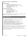
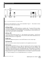
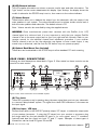
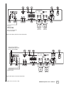
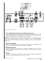
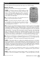
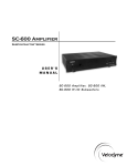
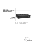
SC-602 Amplifier
SubContractor™ Series
USER’S
MANUAL
S C - 6 0 2 A m p l i f i e r, S C - 6 0 0 I W,
SC-600 IF/IC Subwoofers
.
www.velodyne.com
SC-602 Amplifier User’s Manual
i
Ta b l e o f C o n t e n t s
Congratulations . . . . . . . . . . . . . . . . . . . . . . . . . . . . . . . . . . . . . . . . . . . . . . . . . . . .1
Product Features . . . . . . . . . . . . . . . . . . . . . . . . . . . . . . . . . . . . . . . . . . . . . . . . . . .1
– SC-602 Subwoofer Amplifier . . . . . . . . . . . . . . . . . . . . . . . . . . . . . . . . . . . . . . . . .1
– SC-600 IW, SC-600 IF/IC Subwoofers . . . . . . . . . . . . . . . . . . . . . . . . . . . . . . . . . .2
Setup Checklist . . . . . . . . . . . . . . . . . . . . . . . . . . . . . . . . . . . . . . . . . . . . . . . . . . . .2
Installation . . . . . . . . . . . . . . . . . . . . . . . . . . . . . . . . . . . . . . . . . . . . . . . . . . . . . . .3
– Front Panel Controls and Displays . . . . . . . . . . . . . . . . . . . . . . . . . . . . . . . . . . . . .3
– Rear Panel Connections . . . . . . . . . . . . . . . . . . . . . . . . . . . . . . . . . . . . . . . . . . . .4
Rear Panel Connections - Detailed Explanation . . . . . . . . . . . . . . . . . . . . . . . . . . . . . . .9
– About Low-Pass Crossovers . . . . . . . . . . . . . . . . . . . . . . . . . . . . . . . . . . . . . . . . .9
– A Word About Your Home Theater Receiver’s Crossover and the SC-602
Amplifier’s Crossover . . . . . . . . . . . . . . . . . . . . . . . . . . . . . . . . . . . . . . . . . . . . . .9
– A Word About Interconnect Cables . . . . . . . . . . . . . . . . . . . . . . . . . . . . . . . . . . .10
– A Word About Subwoofer Placement . . . . . . . . . . . . . . . . . . . . . . . . . . . . . . . . . .10
Selecting the Subwoofer to be Controlled
. . . . . . . . . . . . . . . . . . . . . . . . . . . . . . . . .11
Usage . . . . . . . . . . . . . . . . . . . . . . . . . . . . . . . . . . . . . . . . . . . . . . . . . . . . . . . . .12
Restore Defaults . . . . . . . . . . . . . . . . . . . . . . . . . . . . . . . . . . . . . . . . . . . . . . . . . .15
Care of Your Amplifier
. . . . . . . . . . . . . . . . . . . . . . . . . . . . . . . . . . . . . . . . . . . . . .15
Troubleshooting and Service . . . . . . . . . . . . . . . . . . . . . . . . . . . . . . . . . . . . . . . . . .16
Specifications . . . . . . . . . . . . . . . . . . . . . . . . . . . . . . . . . . . . . . . . . . . . . . . . . . . .17
Appendix A: RS-232 Serial Overview and Commands . . . . . . . . . . . . . . . . . . . . . . . . .18
Velodyne Products . . . . . . . . . . . . . . . . . . . . . . . . . . . . . . . . . . . . . . . . . . . . . . . . .20
Warranty . . . . . . . . . . . . . . . . . . . . . . . . . . . . . . . . . . . . . . . . . . . . . . . . . . . . . . .21
.
www.velodyne.com
SC-602 Amplifier User’s Manual
ii
Congratulations
Congratulations on your purchase of a Velodyne SubContractor (SC) Series 602 amplifier
and subwoofer. This system represents the state-of-the-art in low frequency reproduction. Read
and follow the instructions below to ensure safe and proper system operation.
Warning!
To prevent fire or shock hazard, do not expose this equipment to rain or moisture. To avoid
electrical shock, do not open the speaker enclosure or the amp chassis cover. Please observe
all warnings on the equipment itself. There are no user serviceable parts inside. Please refer
all service questions to your authorized Velodyne dealer.
Prior to Installation
Please unpack the system carefully. Please save the carton and all packaging materials
for future use. Record the serial number in the space provided on the warranty card and
page 21 of this manual for future reference.
Product Features
SC-602 SUBWOOFER AMPLIFIER
•
•
•
•
•
•
•
•
•
•
•
•
•
•
•
•
•
•
•
.
400 (x2) watts dynamic/200 (x2) watts RMS high efficiency, Class D
Twin-amplifier configuration easily drives two SC-600 Series subwoofers
DSP-controlled
Four selectable presets for customized listening mode
Automatic 5-band room equalizer (microphone included)
Night-mode setting
Mute control
Line-level (RCA) inputs and outputs
Speaker-level inputs with five way binding post connections
Signal sensing auto turn on/off (defeatable)
Variable volume control
Selectable phase control (0, 90, 180 or 270 degrees)
Built-in adjustable (30-160 Hz) digital low-pass crossover with 24 dB/octave slope
Driver Displacement Control software to prevent over excursion and amp clipping
Blue power indicator LED
RS-232 Serial Interface
12 Volt trigger
Universal IR repeater mini-jack
Preset-specific subsonic filter
www.velodyne.com
SC-602 Amplifier User’s Manual
1
S C - 6 0 0 I W, S C - 6 0 0 I F / I C S U B W O O F E R S
SC-600 IW (In-Wall):
- Two high excursion 6.5” active drivers, two 12.5” x 3” oval
passive radiators with ribbed rubber surround
- High-excursion rubber surrounds on both active and passive drivers
- 2” 4 layer copper voice coils
- Frequency Response: 37-120 Hz (+/- 3 dB)
- 4 ohm impedance
SC-600 IF/IC (In-Floor/In-Ceiling):
- 12” (9.7” piston diameter) subwoofer
- 2.5” 4 layer copper voice coils
- Oversized spider for linearity at high excursion
- High-excursion rubber surround
- Frequency Response: 25-120 Hz (+/- 3 dB)
- 4 ohm impedance
Note: The SC-600 IW and the SC-600 IF/IC must be driven with either the SC-600 or SC-602
amplifier. Use of any other power source voids the warranty.
Setup Checklist
Be sure to do the following to ensure the best performance from your subwoofer:
❑ If possible, optimize the placement of the subwoofer(s) in the listening area.
See page 10 of the User’s Manual.
❑ Install and wire the subwoofer per the instructions on pages 3 - 8.
❑ Set the amp to the proper subwoofer model per the instructions on page 11.
❑ Select the proper volume level. See page 4.
❑ Select the proper low-pass crossover frequency. See pages 9 - 10.
❑ Equalize the subwoofer using the microphone and Auto-EQ feature. See page 12.
❑ Adjust the phase control on the remote to the correct setting. See page 12.
❑ Select the correct preset for the source material. See page 13 - 14.
Your new Velodyne subwoofer system provides for a number of installation options. Read all the
installation information below in order to determine which installation option is best for your
system. Remember to perform all installation procedures with system power turned off.
Note: For proper setup and installation of the SC-600 IW (In-Wall) subwoofer, please refer to
the SC-600 IW Quick Install Guide.
.
www.velodyne.com
SC-602 Amplifier User’s Manual
2
I n s ta l l a t i o n
F R O N T P A N E L C O N T R O L S A N D D I S P L AY S
F R O N T P A N E L C O N T R O L S A N D D I S P L AY S
602
Figure 1: Front Panel Connections of the SC-602 amplifier.
Following are brief descriptions of the controls described in Figure 1. More detail on these
controls can be found in the next section.
(1) Power Switch
This button forces your SC-602 amplifier into standby mode. The power LED turns amber,
the numeric LED shuts off, and the amplifier puts out no power. The unit will remain in this
mode until the POWER button is pressed again. To fully deactivate (i.e. power down) the unit,
use the main power switch on the back panel.
(2) Power LED
This LED illuminates when the power is on. Blue indicates normal operation. The LED turns
amber when the unit is in standby mode or the remote has been used to deactivate the unit,
and dims when the unit is in night mode.
(3) Mic Input
Connect the supplied microphone for the Auto-EQ feature to this mini-jack input.
(4) Remote Eye
This is the eye that receives infrared commands from the supplied remote control.
(5) Crossover
Use these UP and DOWN buttons to select the frequency below which all signals will be
routed to the subwoofer (for example, 80 Hz), rather than to the main speakers. The
frequency is briefly indicated on the LED display, then the display reverts to showing the
subwoofer’s volume level. The slope is fixed at 24 dB/octave. To deactivate the crossover,
press BOTH the UP and DOWN crossover buttons at the same time - two dashes on the
display indicate the crossover is deactivated and the woofer plays all frequencies presented
to it. Please see page 8 for a more detailed discussion on crossovers.
.
www.velodyne.com
SC-602 Amplifier User’s Manual
3
(6) LED Numeric Indicator
This LED supplies information on volume, crossover, woofer type, and other information. The
“light” button on the remote deactivates this display. Upon startup, the display shows the
model of subwoofer the SC-602 amp is set to, then reverts to the volume indicator.
(7) Volume Control
These buttons allow you to balance the output from the subwoofer with the output of the
main speakers in your system. The volume should be set to achieve similar volume level of
both the main speakers and subwoofer. The default volume is 30.
Note: Volume can also be controlled by using the supplied remote.
WARNING: Some manufacturers preset their receivers with the Sub-Out (a.k.a. LFE)
channel signal at a minimum level. It is very important to verify that your receiver Sub-Out
channel is set to the same output level as your front right and left channels. Refer to your
receiver manual for the individual channel level adjustment procedure. If your receiver
Sub-Out channel is set too low, the subwoofer may appear to have a weak output, it may
sound noisy or distorted, and the Auto On/Off feature may not operate properly.
(8) Optional Rack Mount Ears (Included)
These ears can be attached to the SC-602 amp to allow standard 19” rack mounting.
REAR PANEL CONNECTIONS
Following are brief descriptions described in Figure 2. More detail on these controls can be
found in the next section.
13
14
ALWAYS ON
15
19
20
STANDBY MODE
FUSE LOCATION
-
9
10
11 12
16
17
18
21
Figure 2: Rear Panel Connections of the SC-602 amplifier.
(9) Thru Jacks
These RCA connectors are for passing along the same signal that goes into your subwoofer
to a second “daisy-chained” system. The signal from these RCA connectors is the same as
the input signal.
.
(10) Line Input / LFE Input
Connect these jacks to the LINE OUT preamp output, LFE output, or subwoofer output jacks
of your receiver/processor. If using the LFE output from your receiver or processor, plug
the single cable into the jack labeled LFE input or, for more signal, use a “Y” connector
(optional) and feed the signal into both “R” and “L” inputs. Examples of these types of
connections can be found in Figures 2A and 2B.
www.velodyne.com
SC-602 Amplifier User’s Manual
4
Line-Level
Subwoofer Signal
from Source (LFE)
SC-600
Subwoofer
SC-600
Subwoofer
Note: A “Y” connector can
be used as an option.
Figure 2A: Mono (LFE) Line-Level Connection.
Stereo Line-Level Output to
Another System, e.g. a second
SC-600 or SC-602 amplifier
Stereo Line-Level
Input from Source
SC-600
Subwoofer
SC-600
Subwoofer
Figure 2B: Stereo Line-Level Connection.
.
www.velodyne.com
SC-602 Amplifier User’s Manual
5
(11) IR Input
An IR repeater can be connected to this mini-jack.
(12) 12V Trigger
When this 2-conductor mini-jack is connected, the amplifier remains in power-off mode until
the trigger is applied. The correct trigger is +12V on the tip of the connector relative to the
grounded sleeve.
(13) RS-232 In
Use this port to communicate with an RS-232 controlled touch panel system. See Appendix
A for an explanation of the use of the serial port, available commands and their formats.
(14) Signal Sensing Auto On/Off Switch
With this switch in the “standby” position, your subwoofer can be safely left with the main
power switched on continuously. The subwoofer amplifier will turn itself on automatically when
an audio signal is present. If no signal is present for approximately 10 minutes, the unit will
switch to standby mode. While in standby mode, your subwoofer amplifier will draw very
minimal power. This function can be disabled by leaving the switch in the “always on” position.
(15) Speaker Level Input Terminals
If you do not connect the SC-602 amplifier to your receiver using the line input/LFE input
connection (Item 10) connect these input terminals to the speaker output terminals of your
amplifier or receiver. If you use this method of connection, make sure to select the “large”
speaker option in the receiver’s speaker set-up menu. Also, select the option for no
subwoofer. This will make sure all bass and LFE information is fed to the speaker outputs and
be received by your SC-602 amplifier.
Note: Using both speaker terminals and the line level inputs is not recommended, as this may
damage the SC-602 amplifier or your receiver.
(16) Speaker Level Output Terminals
These connections send a crossed-over speaker-level signal to the front speakers. When
connected in this fashion, your satellite speakers will be crossed over at 80 Hz. This removes
the task of reproducing frequencies below 80 Hz from your satellites, enabling them to do a
better job reproducing high frequencies.
You may also connect your satellites directly to your receiver or amplifier along with the
subwoofer if you wish to bypass this crossover.
An example of a speaker-level connection is shown in Figure 3.
.
www.velodyne.com
SC-602 Amplifier User’s Manual
6
Speaker-Level Signal
from Source
80 Hz and Above to
Satellite Speakers
SC-600
Subwoofer
SC-600
Subwoofer
Figure 3: Speaker-Level Connection.
(17) and (18) Subwoofer Connection 5-way Binding Post Terminals
Connect the output terminals to the subwoofer being controlled by the SC-602 amplifier. Only
connect ONE subwoofer to each red/black pair of subwoofer output terminals - DO NOT
connect multiple subwoofers to the terminals in any configuration.
Caution!!! To avoid damage to your SC-602 amp and subwoofer, be sure to maintain correct
polarity when making all speaker connections; red (positive) to red, and black (negative)
to black. Be sure that all connections are tight, and that there are no loose strands or
frayed wires.
(19) Power Cord Adapter
Connect the detachable power plug to this male interface connection. The detachable cord
allows for easy replacement should the original become damaged.
(20) Main Power Switch
Press the POWER switch to the ON position to activate the amplifier. If the unit is to be left
unused for an extended period of time, move this switch to the OFF position to prolong the
life of the amplifier.
.
(21) Fuse
If the unit is not functioning, check the fuse. If the fuse is blown, replace with an identically
rated fuse. If the fuse blows again, refer the unit for service.
www.velodyne.com
SC-602 Amplifier User’s Manual
7
R e a r Pa n e l C o n n e c t i o n s — D e ta i l e d E x p l a n a t i o n
The SC-602 amplifier is equipped with both speaker-level and line-level inputs. Use the
RCA/Phono type “INPUT” jacks when connecting from a pre-amp, signal processor, or line-level
crossover. The “SPEAKER LEVEL INPUT” jacks connect directly to the speaker outputs of an
integrated amplifier or receiver. Your amplifier section will notice no additional loading effects
when you use these inputs because of their high impedance.
Note: Do not use both the RCA/Phono “INPUT” connections and “SPEAKER LEVEL INPUT”
connections simultaneously.
ABOUT LOW-PASS CROSSOVERS
All of the SC-602 amplifier inputs sum the left and right channels together and the resulting
signal is passed through an adjustable low-pass crossover before being amplified. The crossover
control allows you to adjust the upper limit of the subwoofer’s frequency response from 30 to
160 Hz. The subwoofer’s response will begin rolling off above the frequency you set this control
to. The slope is 24 dB/octave.
You should set the crossover frequency to obtain a smooth and seamless transition from the
subwoofer to the main speakers in your system. If your main speakers are small with limited
low frequency output, you may wish to choose a higher frequency (such as 100 -120 Hz) than
you would with larger speakers which have greater low frequency output. The SC-602 amp’s
crossover has a default of 80 Hz.
Most receivers and processors provide a menu option in which you can characterize main
speakers as “large” or “small” speakers. This affects the bass signals passed to the main
speakers. We recommend in most cases setting the main speakers to “small,” despite their
size and frequency response characteristics, allowing all multi-channel bass and LFE signals to
be passed to the SC-602. This is because the powerful 400 (x2) watt SC-602 amp combined
with the SC-600 subwoofer are more likely suited to low bass reproduction than your amp and
main speakers. With the burden of low frequency reproduction relieved, your speakers will
exhibit better performance, and your overall system performance will improve.
Disabling the Low-Pass Crossover (Subwoofer Direct)
If your receiver/processors provides a crossed-over signal to the subwoofer you may want to
bypass the SC-602 amp’s low-pass crossover. To do this, depress both the Crossover UP and
indicating that the
Crossover DOWN buttons simultaneously. The numeric LED will show
low-pass crossover has been defeated. To reactivate the low-pass crossover, simply push the
Crossover UP or Crossover DOWN buttons.
--
A WORD ABOUT YOUR HOME THEATER RECEIVER’S
CROSSOVER AND THE SC-602 AMPLIFIER’S CROSSOVER
Your Velodyne SC-602 amplifier is designed to operate using the full range audio signal for
input when using the built-in crossover. Many home theater processors/receivers have a
“subwoofer out” jack that performs this same function and are designed to be used with
a powered subwoofer.
.
www.velodyne.com
SC-602 Amplifier User’s Manual
8
In these installations, you may want to bypass the crossover in either the processor or the
Velodyne SC-602 amplifier as described above. However, in some cases you may want to use
BOTH crossovers. If you choose to do this you should stagger the frequencies, (i.e., 120 Hz
subwoofer, 80 Hz processor) for best results.
Note: If not using an external crossover, you should use the subwoofer’s built-in crossover for
optimal performance. When using a single RCA sub out from the processor, it does not matter
which line level input (L/R) is used.
A WORD ABOUT INTERCONNECT CABLES
When connecting the Velodyne SC-602 amplifier to your subwoofer using the speaker level
connections, use a high quality speaker cable. It is recommended that you keep the length of
cable as short as possible to avoid any potential external interference problems.
When connecting the SC-602 amplifier to your subwoofer, use a quality speaker cable that is
at least 14-gauge. Be very careful to avoid any loose or frayed strands that could result in a
short, causing a dangerous condition and possible damage to your unit. Cables of extremely
large size are typically not required. Extremely large gauge wire may not properly fit in the
binding posts, resulting in a poor connection and possible short circuits.
A WORD ABOUT SUBWOOFER PLACEMENT
Subwoofers operate at extremely low frequencies, which are primarily omni-directional. Keep in
mind that frequency response and output level can be drastically influenced by room placement,
depending on the acoustic properties of the listening room. Typically, the optimum
location for a subwoofer is in a front corner of your listening room where the greatest output
levels and optimum low frequency extension can be found. Typically, a minimum distance of one
to two feet from your TV to the subwoofer will be adequate to avoid any magnetic interference.
Remember that the built-in 5-band EQ will help to get the most performance out of your
subwoofer no matter where it is placed.
Caution!
This amplifier is an electronic device. Do not place the amplifier next to sources of heat such
as furnace registers, radiators, etc. Likewise, do not place the amplifier near sources of
excessive moisture such as evaporative coolers, humidifiers, etc. The power cord should be
routed in such a way that it will not be walked on, pinched or compressed in any way that could
result in damaging the insulation or wire.
.
www.velodyne.com
SC-602 Amplifier User’s Manual
9
Selecting the Subwoofer to be Controlled
Your SC-602 amplifier can control the Velodyne SC-600 Series subwoofers as well as generic
passive subwoofers. Special internal software settings are designed to maximize performance
and reliability depending on the model of subwoofer being controlled, so it is important to match
the SC-602 amplifier with the subwoofer it is controlling. The SC-602 amplifier comes with a
default setting for the SC-600 IW subwoofer. When the unit is first powered up, the model
setting is displayed for two seconds on the numeric LED before the display reverts to the volume
setting. The subwoofer to be controlled is shown as follows:
Model
LED Display
SC-600 IW (In-Wall)
IW
SC-600 IF (In-Floor)
IF
SC-600 IC (In-Ceiling)
IC
Generic Subwoofer
GS
Note: Both the IF and the IC settings apply to the SC-600 In-Floor/In-Ceiling (IF/IC) subwoofer
and have identical internal settings.
To change the subwoofer to be controlled, first power down the amplifier using the main power
switch on the back panel (DO NOT use the power button on the front panel). Then, turn the
switch on while depressing any of the buttons on the front panel (crossover up or down, or
volume up or down). The unit will show the model it is currently controlling. To change the
model, simply push the crossover up or crossover down buttons and the model changes on the
LED display. Once the desired model is seen on the LED display, simply release the button. You
don’t need to do anything else - the model to be controlled is automatically stored in the
SC-600 amp’s memory. To exit model selection mode, use the main power switch on the back
panel to power down and power up the unit. You should see the model you selected for two
seconds on the LED display before the display reverts to the volume.
Note: The SC-602 amplifier can easily control two subwoofers of the same type, i.e.,
two SC-600 IW or two SC-600 IF/IC subs. It is not intended to drive one of each
type simultaneously.
.
www.velodyne.com
SC-602 Amplifier User’s Manual
10
Usage
This section addresses EQ set-up and day-to-day usage of your SC-602 amplifier.
Remote Control
The features of the SC-602 remote control are listed below.
• POWER — This button forces your SC-602 amplifier unit into
standby mode. The power LED turns amber, the numeric LED
shuts off, and the amplifier puts out no power. The unit will
remain in this mode until the POWER button is pressed again.
To fully deactivate (i.e. power down) the unit, use the main
power switch on the back panel.
Note: The master power switch on the rear panel must be on
in order for the front power button to function.
• MUTE — This button mutes the subwoofer’s output. The LED
on the amplifier will show 00 if the unit is muted. To unmute
the subwoofer, press the MUTE button again and the original
volume setting shows on the LED.
Figure 4: SC-602 Remote.
• EQ — This button automatically equalizes the subwoofer’s frequency response using a 5-band
internal graphic equalizer. Prior to engaging this feature, hook up either one or two SC-600
subwoofers to the SC-602 amplifier. To use this feature, first plug the supplied microphone
into the Mic-In jack on the front panel of the amplifier and place the mic in your preferred
listening position. Then press EQ on the remote for about 2-3 seconds. The subwoofer(s)
emits 12 “sweep tones” that cover the frequencies between 20 and 150 Hz. The LED
displays “AU” during the Auto-EQ process. After the sweeps are complete, the unit saves its
EQ settings and returns to normal operation. To prevent accidental invocation of the EQ
feature, you must hold down the EQ button for 2-3 seconds before the EQ sweeps begin.
Note: Each time the EQ feature is utilized, the EQ settings for the SC-602 amplifier are reset.
If the microphone is not plugged in, the SC-602 amplifier will emit one or two sweep tones then
cease the EQ operation. In this case, the previous EQ settings will be preserved.
• PHASE — These buttons allow you to optimize the subwoofer performance for the location
and your listening position. Play some bass-heavy music. While listening, push one of the four
phase buttons, listen for a few moments, and then press the next phase button. In most
installations, one of the four button positions will offer an audibly better blend of subwoofer
and speakers. Selecting the correct phase position is that easy. The LED will show the phase
selected by showing “PH” followed by the phase number: 0, 90, 180 or 270.
• LIGHT — If you wish, you can deactivate the numeric LED on your SC-602 amplifier. To
do this, press the LIGHT button on your remote. To reactivate the LED, press the LIGHT
button again.
• NIGHT — Night mode limits the maximum dynamic output of the subwoofer for late night
listening or to be more considerate of close neighbors. Press the night button to turn the
.
www.velodyne.com
SC-602 Amplifier User’s Manual
11
night mode feature on or off. Activation of night mode causes “n” to appear briefly on
the display. When night mode is deactivated, the display shows “n off” and then returns to
normal function.
• VOLUME CONTROL — This control allows you to balance the output from the subwoofer with
the output of the main speakers in your system. This control should be set to achieve similar
volume level of both the main speakers and subwoofer. When pressing volume up or down,
the volume level change is shown on the numeric LED on the front panel.
WARNING: Some manufacturers preset their receivers with the Sub-Out channel signal at a
minimum level. It is very important to verify that your receiver Sub-Out channel is set to the
same output level as your front right and left channels. Refer to your receiver manual for the
individual channel level adjustment procedure. If your receiver Sub-Out channel is set too low,
the subwoofer may appear to have a weak output, it may sound noisy or distorted, and the
Auto On/Off feature may not operate properly.
Note: The volume can also be adjusted via the volume buttons on the front panel of the
amplifier. These buttons have the same effect as pressing the up and down volume buttons on
your remote.
• PRESETS — There are four presets, consisting of Movies, R&B – Rock, Jazz – Classical, and
Games. As a preset is chosen, the preset is shown on the numeric LED as P1 for preset 1,
P2 for preset 2, etc. The presets provide the following characteristics for bass reproduction:
Movies:
Maximum output and impact for explosions and other
action adventure movie content.
R&B – Rock:
Provides the driving bass found in today’s rock music.
Jazz – Classical: The tightest, cleanest, lowest distortion bass. The flattest frequency
response of the four presets.
Games:
Maximum loudness available for the impact of video games.
Each preset has its own characteristics with respect to subsonic filter, volume differential and
a single contour equalizer in order to optimize the listening mode for the preset.
.
www.velodyne.com
SC-602 Amplifier User’s Manual
12
The following table indicates musical style and which preset is recommended for it.
MUSICAL STYLE
Action Adventure Movies
Country – Rock
Country – Soft
Folk
Indie Music
Pop
Rock
Alternative Rock
Blues
Broadway and Vocalists
Children’s Music
Christian and Gospel
Classic Rock
Classical
Dance and DJ
Hard Rock/Heavy Metal
Latin Music
Miscellaneous
Movies – Non-Action Adventure
New Age
Opera and Vocal
R&B
Rap and Hip-Hop
Soundtracks
Video Games
.
www.velodyne.com
SUGGESTED PRESET
Movies
R&B – Rock
Jazz – Classical
Jazz – Classical
R&B – Rock
R&B – Rock
R&B – Rock
Jazz – Classical
Jazz – Classical
Jazz – Classical
Jazz – Classical
Jazz – Classical
R&B – Rock
Jazz – Classical
R&B – Rock
R&B – Rock
R&B – Rock
Jazz – Classical
Jazz – Classical
Jazz – Classical
Jazz – Classical
R&B – Rock
R&B – Rock
R&B – Rock or Jazz – Classical
Games
SC-602 Amplifier User’s Manual
13
R e s t o r i n g D e fa u l t s
There is a feature that allows you to restore default settings for your SC-602 amplifier. By
pressing presets in EXACTLY the following order on the remote, the unit’s power light will blink
indicating that you have restored defaults.
Preset
Preset
Preset
Preset
Preset
Preset
Preset
Preset
1:
2:
3:
4:
4:
3:
2:
1:
Movies
R&B – Rock
Jazz – Classical
Games
Games
Jazz – Classical
R&B – Rock
Movies
When you press the presets in the above order, the numeric LED will display “P3” indicating that
you have restored defaults. The unit’s volume is reset to level 30 on a scale of 1 to 80.
C a r e o f yo u r A m p l i f i e r
Do not use any harsh detergents or chemicals to clean the SC-602 chassis. Abrasives,
detergents, or cleaning solutions will damage the finish on the SC-602 chassis. We recommend
using a damp cloth to clean the front, back and sides. Do not allow any liquids to enter the
SC-602 chassis.
During normal conditions, the amplifier may be left on continuously without any problems. If you
plan to leave the unit unused for an extended period of time, we recommend that you turn off
the unit by the master power switch on the rear panel.
.
www.velodyne.com
SC-602 Amplifier User’s Manual
14
T roubleshooting and Service
Before seeking service for your amplifier or subwoofer, please re-check all systems. Following
is a simple troubleshooting guide to assist you.
1.
2.
3.
4.
5.
Verify that the unit is plugged in and power outlet used is active.
Is the power switch on?
Is the unit receiving an input signal from your receiver or processor?
Have all controls on the amplifier (volume, crossover, phase, etc.) been properly set?
If the unit has been running at high levels, one of the protection circuits may be engaged.
Has the amplifier overheated?
6. Has the power button been depressed on the remote?
7. Is the remote non-responsive? We recommend replacing the batteries in the remote.
If the protection circuitry is active, the unit may cycle on and off until operating parameters
return to normal. Under more serious conditions, the unit may shut off completely. Normal
operation should return upon cooling, but you may be required to turn the power off and then
on again to reset the unit.
The following conditions require service by a qualified technician:
1. The power cord has become damaged
2. The unit does not appear to operate normally or exhibits a marked
change in performance
3. The unit has been exposed to water
4. Some part of the chassis or circuitry is physically damaged
Thank You for Purchasing an SC-602 Amplifier!
.
www.velodyne.com
SC-602 Amplifier User’s Manual
15
Specifications
www.velodyne.com
SC-602 Amplifier User’s Manual
16
Appendix A: RS-232 Serial Overview and Commands
Introduction
This document outlines Velodyne’s SubContractor (SC) RS-232 protocol specification. This
protocol indicates how SC products receive run-time commands from devices such as Creston®
Universal Remote Controls.
Com Port Setup
Use standard communications settings: Baud Rate: 9600, Data Bits: 8, Parity: None,
Stop Bits: 1
SC IN and OUT Port Pin Configuration
SC serial ports use a standard configuration that allows direct connection to a PC via a FEMALE
to MALE serial cable. It uses only three pins (Transmit, Receive, Ground).
The pin configurations are:
IN:
Pin 2 = Transmit
Pin 3 = Receive
Pin 5 = Ground
OUT:
Pin 2 = Receive
Pin 3 = Transmit
Pin 5 = Ground
Runtime Command Format
.
Byte Number
Byte Description
Notes
0
‘#’
Header Character
1 to 3 or 4
Command and
Parameter Data
3 to 4 ASCII characters see formats below
Case sensitive - CAPS ONLY!
4 or 5
‘$’
Termination Character (required or
command is ignored)
www.velodyne.com
SC-602 Amplifier User’s Manual
17
RS-232 Commands
.
Activity
Command
Format
Acceptable
n Values
Example(s)
Comments
Volume Control
#VOnn$,
#VO+$,
#VO-$,
#VO?$
00 – 80
#VO25$,
#VO+$,
#VO-$,
#VO?$
Sets volume to a value,
increments volume up
or down, or requests
current volume setting
Preset Control
#PSn$,
#PS?$
1, 2, 3, 4
#PS1$, #PS2$,
#PS3$, #PS4$,
#PS?$
Activates the indicated
preset, or requests
the current preset
Logo Light
Control
#LTn$,
#LT?$
0: Light Off
1: Light On
#LT0$
#LT1$
#LT?$
Turns the Logo Light
on or off, or requests
light state
Night Mode
Control
#NMn$,
#NM?$
0: Night
Mode Off
1: Night
Mode On
#NM0$
#NM1$
#NM?$
Activates/Deactivates
Night Mode, or
requests light
mode state
Mute Control
#MUn$,
#MU?$
#MU0$
0: Mute Off
1: Mute On
#MU1$
#MU?$
Mutes/Unmutes the
woofer, or requests
mute state
Power Control
#JUn$,
#JU?$
0: Power Off
1: Power On
#JU0$
#JU1$
#JU?$
Powers On/Powers
Off the woofer, or
requests power state
www.velodyne.com
SC-602 Amplifier User’s Manual
18
Velodyne Products
115 - 120V
DD ® Series
DD-10
DD-12
DD-15
DD-18
Digital Drive 1812
Signature Edition
DEQ-R Series
DEQ-8R
DEQ-10R
DEQ-12R
DEQ-15R
DLS™-R Series
DLS -3500R
DLS -3750R
DLS -4000R
DLS -5000R
Impact Series
Impact - Mini
Impact -10
Impact -12
220 - 240V
MiniVee®
®
MiniVee 10
Optimum Series
Optimum-8
Optimum-10
Optimum-12
SMS™-1
SubContractor™
Series
SC-1250
SC-10
SC-12
SC-15
SC-IW
SC-IF/IC
SC-600 Amp
SC-602 Amp
SC-600 IW
SC-600 IF/IC
DD ® Series
DD-10
DD-12
DD-15
DD-18
Digital Drive 1812
Signature Edition
CHT-Q Series
CHT-8Q
CHT-10Q
CHT-12Q
CHT-15Q
Impact Series
Impact - Mini
Impact -10
Impact -12
MicroVee™
SPLi Series
SPL-800i
SPL-1000i
SPL-Ultra Series
SPL-800 Ultra
SPL-1000 Ultra
SPL-1200 Ultra
SubContractor™
Series
SC-1250
SC-10
SC-12
SC-15
SC-IW
SC-IF/IC
SC-600 Amp
SC-602 Amp
SC-600 IW
SC-600 IF/IC
SMS™ -1
VX-11
MicroVee™
.
www.velodyne.com
SC-602 Amplifier User’s Manual
19
FOR YOUR RECORDS. . .
Date Purchased_________________________________________________________________
Dealer_________________________________________________________________________
Serial #________________________________________________________________________
*NOTE: Please complete and return your warranty card within ten (10) days or
Register. . . ON LINE . . . It’s faster . . . and easier
www.velodyne.com
.
www.velodyne.com
SC-602 Amplifier User’s Manual
20
Velodyne Acoustics, Inc.
345 Digital Drive
Morgan Hill, CA 95037
408.465.2800 voice
408.779.9227 fax
408.779.9208 service fax
www.velodyne.com
Service E-mail: [email protected]
Product E-mail: [email protected]
Technical E-mail: [email protected]
.
63-SC602
RevC JUN 2013
www.velodyne.com