1
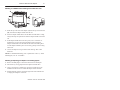
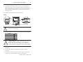
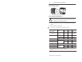
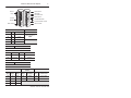
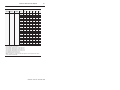
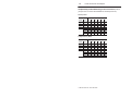
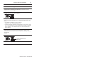
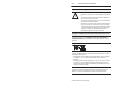
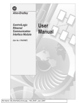
Installation Instructions (Cat. No. 1794-ASB Series D) 9 1 2 3 4, 5 8 7 6 This Adapter module is shipped configured for Standard Addressing Mode. In Standard Addressing Mode, this module can be used as a replacement for 1794-ASB Series A or B remote I/O adapters. Note: This adapter cannot be used with PLC-2 programmable controllers.This series D adapter can communicate with FLEX Integra analog modules. Component Identification 1 Remote I/O Adapter module 2 Indicators 3 Communication reset pushbutton (PRL) 4 Access door to switches S1 and S2 5 Switches S1 and S2 (behind access door) 6 Remote I/O cable connector 7 +24V dc connections 8 24V common connections 9 Flexbus connector FLEX I/O is a trademark of Rockwell Automation. FLEX Integra is a trademark of Rockwell Automation. Publication 1794-5.46 – November 1998 2 FLEX I/O Remote I/O Adapter European Union Directive Compliance If this product has the CE mark it is approved for installation within the European Union and EEA regions. It has been designed and tested to meet the following directives. EMC Directive This product is tested to meet Council Directive 89/336/EEC Electromagnetic Compatibility (EMC) and the following standards, in whole or in part, documented in a technical construction file: • • EN 50081-2EMC – Generic Emission Standard, Part 2 – Industrial Environment EN 50082-2EMC – Generic Immunity Standard, Part 2 – Industrial Environment This product is intended for use in an industrial environment. Low Voltage Directive This product is tested to meet Council Directive 73/23/EEC Low Voltage, by applying the safety requirements of EN 61131–2 Programmable Controllers, Part 2 – Equipment Requirements and Tests. For specific information required by EN 61131-2, see the appropriate sections in this publication, as well as the following Allen-Bradley publications: • • Industrial Automation Wiring and Grounding Guidelines For Noise Immunity, publication 1770-4.1 Guidelines for Handling Lithium Batteries, publication AG-5.4 This equipment is classified as open equipment and must be mounted in an enclosure during operation to provide safety protection. Publication 1794-5.46 – November 1998 FLEX I/O Remote I/O Adapter 3 Mounting on a DIN Rail before installing the terminal base units A B C C 1. Hook the lip on the rear of the adapter (A) onto the top of the DIN rail (B), and rotate the adapter module onto the rail. 2. Press the adapter module down onto the DIN rail until flush. Locking tab (C) will snap into position and lock the adapter module to the DIN rail. 3. If the adapter module does not lock in place, use a screwdriver or similar device to move the locking tab down while pressing the adapter module flush onto the DIN rail and release the locking tab to lock the adapter module in place. If necessary, push up on the locking tab to lock. 4. Connect the adapter wiring as shown under “Wiring” later in this document. NOTE: For Panel/Wall mounting, refer to publication 1794-5.13, “Panel Mounting Kit, Cat. No. 1794-NM1.” Mounting (or Replacing) the Adapter on an Existing System 1. Remove the RIO plug-in connector from the front of the adapter. 2. Disconnect any wiring jumpered to the adjacent terminal base. 3. Using a screwdriver or similar tool, open the lock and remove the module from the base unit to which the adapter will be attached. 4. Push the flexbus connector toward the right side of the terminal base to unplug the backplane connection. Publication 1794-5.46 – November 1998 4 FLEX I/O Remote I/O Adapter ATTENTION: Make certain that the flexbus ! connector is completely clear of the adapter. The slide must be completely to the right and the raised spot on the slide visible. 5. Release the locking tab and remove the adapter. 6. Before installing the new adapter, notice the notch on the right rear of the adapter. This notch accepts the hook on the terminal base unit. The notch is open at the bottom. The hook and adjacent connection point keep the terminal base and adapter tight together, reducing the possibility of a break in communication over the backplane. ATTENTION: Make certain that the hook on the ! terminal base is properly hooked into the adapter. Failure to lock the hook into the adjacent base/adapter can result in loss of communication on the backplane. 7. Complete the adapter mounting as shown below. Push down and in at the same time to lock the adapter to the DIN rail. When the adapter is locked onto the DIN rail, gently push the flexbus connector into the adapter to complete the backplane. C Publication 1794-5.46 – November 1998 20127 FLEX I/O Remote I/O Adapter 5 8. If the adapter module does not lock in place, use a screwdriver or similar device to move the locking tab C down while pressing the adapter module flush onto the DIN rail. Then release the locking tab to lock the adapter module in place. If necessary, push up on the locking tab to lock. 9. Reinstall the module into the terminal base unit. Wiring Allen-Bradley D ADAPTER ACTIVE FAULT LOCAL FAULT F COM 24 VDC POWER SUPPLY RIO ADAPTER 1794–ASB2 E G 24V 20131 1 SH 2 ! ATTENTION: When connecting wiring, torque terminal screws to 7-9 inch-pounds 1. Connect the remote I/O cable to the removable remote I/O connector. Connect To Blue Wire – RIO 1 Shield Wire – RIO SH Clear Wire – RIO 2 ATTENTION: If this is the last adapter, you must ! terminate the remote I/O link here. Use a terminating resistor connected across terminals 1 and 2. Refer to your processor manual for information on the size of the resistor. 2. Connect +24V dc input to the left side of the lower connector, terminal E. 3. Connect 24V common to the left side of the upper connector, terminal D. 4. Connections G and F are used to pass 24V dc power (G) and 24V common (F) to the next module in the series (if required). Publication 1794-5.46 – November 1998 6 FLEX I/O Remote I/O Adapter 1 2 3 4 5 6 7 8 1 2 3 4 5 6 7 8 Set the Adapter Switches ON ON S1 S2 Flipopen cover Set the Addressing Mode Switches ! ATTENTION: Some switches on this adapter differ from the switches on previous versions. Make certain that you identify each switch before setting. 1. Lift the hinged switch cover on the front of the adapter to expose the switches. 2. Set the switches as shown below. 3. Cycle power to the adapter after setting the switches. When Using this Addressing Mode And Mode 2 Switch 1-1 Mode 1 Switch 2-5 Mode 0 Switch 2-8 Standard (as shipped) 8 and/or 16- point modules See note 1 ON ON Compact 8-point modules OFF ON OFF 16-point modules ON ON OFF Complementary See Complementary Rack Addressing Table, page 10 Primary chassis Complementary chassis Complementary Primary chassis Complementary chassis 8-point modules OFF OFF ON ON OFF ON See Complementary Rack Addressing Table, page 10 16-point modules2 1 OFF OFF OFF ON OFF OFF In Standard mode, this switch retains its function as switch position 1 of rack addressing. In Standard mode, the module is functionally interchangeable with 1794-ASB Series A or B modules. 2 When programming block transfers, address analog modules as module 0 if switch S1-1 is on; module 1 if switch S1-1 is off. Publication 1794-5.46 – November 1998 1 2 3 4 5 6 7 8 First I/O Group I/O Rack Number Mode Switch 2 7 Mode Switch 0 Hold Inputs Rack Fault Select Mode Switch 1 Communication Rate Processor Restart Lockout Hold Last State ON ON S1 S2 First I/O Group I/O Rack Number S1–8 S1–7 I/O group ON ON 0 (1st) OFF ON 2 (2nd) ON OFF 4 (3rd) OFF OFF 6 (4th) S2–8 1 2 3 4 5 6 7 8 FLEX I/O Remote I/O Adapter S1–6 thru S1–1 Refer to the table on page 8 Mode Switch 0 Refer to Mode Selection Switches, page 6 S2–7 Hold Inputs S2–6 Rack Fault Select ON Hold Inputs ON Disabled (default) OFF Reset Inputs OFF Enabled S2–5 Mode Switch 1 Refer to Mode Selection Switches, page 6 Communication Rate Processor Restart Lockout Hold Last State S2–4 S2–3 Bits/s S2–2 Processor: S2–1 Processor will: ON ON 57.6k ON Restart ON Reset Outputs OFF ON 115.2k OFF Locked Out OFF Hold last state ON OFF 230.4k OFF OFF 230.4k Publication 1794-5.46 – November 1998 8 FLEX I/O Remote I/O Adapter I/O Rack Number Switch Settings Rack Number S1 Switch Position 1747-SN PLC–5 PLC–5/250 PLC–3 6 5 4 3 2 1 Rack 0 Not Valid Rack 0 Rack 0 ON ON ON ON ON ON Rack 1 Rack 1 Rack 1 Rack 1 OFF ON ON ON ON ON Rack 2 Rack 2 Rack 2 Rack 2 ON OFF ON ON ON ON Rack 3 Rack 3 Rack 3 Rack 3 OFF OFF ON ON ON ON Rack 4 Rack 4 Rack 4 ON ON OFF ON ON ON Rack 5 Rack 5 Rack 5 OFF ON OFF ON ON ON Rack 6 Rack 6 Rack 6 ON OFF OFF ON ON ON Rack 7 Rack 7 Rack 7 OFF OFF OFF ON ON ON Rack 10 Rack 10 Rack 10 ON ON ON OFF ON ON Rack 11 Rack 11 Rack 11 OFF ON ON OFF ON ON Rack 12 Rack 12 Rack 12 ON OFF ON OFF ON ON Rack 13 Rack 13 Rack 13 OFF OFF ON OFF ON ON Rack 14 Rack 14 Rack 14 ON ON OFF OFF ON ON Rack 15 Rack 15 Rack 15 OFF ON OFF OFF ON ON Rack 16 Rack 16 Rack 16 ON OFF OFF OFF ON ON Rack 17 Rack 17 Rack 17 OFF OFF OFF OFF ON ON Rack 20 Rack 20 Rack 20 ON ON ON ON OFF ON Rack 21 Rack 21 Rack 21 OFF ON ON ON OFF ON Rack 22 Rack 22 Rack 22 ON OFF ON ON OFF ON Rack 23 Rack 23 Rack 23 OFF OFF ON ON OFF ON Rack 24 Rack 24 Rack 24 ON ON OFF ON OFF ON Rack 25 Rack 25 Rack 25 OFF ON OFF ON OFF ON Rack 26 Rack 26 Rack 26 ON OFF OFF ON OFF ON Rack 27 Rack 27 Rack 27 OFF OFF OFF ON OFF ON Rack 30 Rack 30 ON ON ON OFF OFF ON Rack 31 Rack 31 OFF ON ON OFF OFF ON Rack 32 Rack 32 ON OFF ON OFF OFF ON Rack 33 Rack 33 OFF OFF ON OFF OFF ON Rack 34 Rack 34 ON ON OFF OFF OFF ON Rack 35 Rack 35 OFF ON OFF OFF OFF ON Rack 36 Rack 36 ON OFF OFF OFF OFF ON Rack 37 Rack 37 OFF OFF OFF OFF OFF ON Rack 40 ON ON ON ON ON OFF Rack 41 OFF ON ON ON ON OFF Rack 42 ON OFF ON ON ON OFF Rack 43 OFF OFF ON ON ON OFF Rack 44 ON ON OFF ON ON OFF Rack 45 OFF ON OFF ON ON OFF Rack 46 ON OFF OFF ON ON OFF Rack 47 OFF OFF OFF ON ON OFF Rack 50 ON ON ON OFF ON OFF Rack 51 OFF ON ON OFF ON OFF See note 1 – Rack addresses 40 thru 76 are only available in Standard mode. Publication 1794-5.46 – November 1998 FLEX I/O Remote I/O Adapter Rack Number 1747-SN PLC–5 PLC–5/250 9 S1 Switch Position PLC–3 6 5 4 3 2 1 Rack 52 ON OFF ON OFF ON OFF Rack 53 OFF OFF ON OFF ON OFF Rack 54 ON ON OFF OFF ON OFF Rack 55 OFF ON OFF OFF ON OFF Rack 56 ON OFF OFF OFF ON OFF Rack 57 OFF OFF OFF OFF ON OFF Rack 60 ON ON ON ON OFF OFF Rack 61 OFF ON ON ON OFF OFF Rack 62 ON OFF ON ON OFF OFF Rack 63 OFF OFF ON ON OFF OFF Rack 64 ON ON OFF ON OFF OFF Rack 65 OFF ON OFF ON OFF OFF Rack 66 ON OFF OFF ON OFF OFF Rack 67 OFF OFF OFF ON OFF OFF Rack 70 ON ON ON OFF OFF OFF Rack 71 OFF ON ON OFF OFF OFF Rack 72 ON OFF ON OFF OFF OFF Rack 73 OFF OFF ON OFF OFF OFF Rack 74 ON ON OFF OFF OFF OFF Rack 75 OFF ON OFF OFF OFF OFF Rack 76 ON OFF OFF OFF OFF OFF Not Valid OFF OFF OFF OFF OFF OFF Rack address 77 is an illegal configuration. PLC-5/11 processors can scan rack 03. PLC-5/15 and PLC-5/20 processors can scan racks 01–03. PLC-5/25 and PLC-5/30 processors can scan racks 01–07. PLC-5/40 and PLC-5/40L processors can scan racks 01–17. PLC-5/60 and PLC-5/60L processors can scan racks 01–27. PLC-5/80 processors can scan racks 01–27. PLC-5/250 processors can scan racks 00–37. Note 1 – Rack switch 1–1 is used to set a mode in this adapter. As a result. rack addresses from 40 to 76 are only available in Standard mode. Publication 1794-5.46 – November 1998 10 FLEX I/O Remote I/O Adapter Complementary I/O Rack Addressing for PLC-5 Processors (refer to your processor or scanner documentation for all other processors) Primary Rack Rack Number S1 Switch Position 1747-SN PLC–5 6 5 4 3 2 1 Rack 0 Not Valid ON ON ON ON ON OFF Rack 1 Rack 1 OFF ON ON ON ON OFF Rack 2 Rack 2 ON OFF ON ON ON OFF Rack 3 Rack 3 OFF OFF ON ON ON OFF Rack 4 ON ON OFF ON ON OFF Rack 5 OFF ON OFF ON ON OFF Rack 6 ON OFF OFF ON ON OFF Rack 7 OFF OFF OFF ON ON OFF Complementary Rack Rack Number S1 Switch Position 1747-SN PLC–5 6 5 4 3 2 1 Rack 0 Not Valid ON ON ON OFF ON ON Rack 1 Rack 1 OFF ON ON OFF ON ON Rack 2 Rack 2 ON OFF ON OFF ON ON Rack 3 Rack 3 OFF OFF ON OFF ON ON Rack 4 ON ON OFF OFF ON ON Rack 5 OFF ON OFF OFF ON ON Rack 6 ON OFF OFF OFF ON ON Rack 7 OFF OFF OFF OFF ON ON Publication 1794-5.46 – November 1998 FLEX I/O Remote I/O Adapter 11 CSA Hazardous Location Approval CSA certifies products for general use as well as for use in hazardous locations. Actual CSA certification is indicated by the product label as shown below, and not by statements in any user documentation. Example of the CSA certification product label To comply with CSA certification for use in hazardous locations, the following information becomes a part of the product literature for CSA-certified Allen-Bradley industrial control products. • This equipment is suitable for use in Class I, Division 2, Groups A, B, C, D, or non-hazardous locations only. • The products having the appropriate CSA markings (that is, Class I Division 2, Groups A, B, C, D), are certified for use in other equipment where the suitability of combination (that is, application or use) is determined by the CSA or the local inspection office having jurisdiction. Important: Due to the modular nature of a PLC control system, the product with the highest temperature rating determines the overall temperature code rating of a PLC control system in a Class I, Division 2 location. The temperature code rating is marked on the product label as shown. Temperature code rating Look for temperature code rating here The following warnings apply to products having CSA certification for use in hazardous locations. Publication 1794-5.46 – November 1998 12 FLEX I/O Remote I/O Adapter CSA Hazardous Location Approval ! ATTENTION: Explosion hazard — • Substitution of components may impair suitability for Class I, Division 2. • Do not replace components unless power has been switched off or the area is known to be non-hazardous. • Do not disconnect equipment unless power has been switched off or the area is known to be non-hazardous. • Do not disconnect connectors unless power has been switched off or the area is known to be non-hazardous. Secure any user-supplied connectors that mate to external circuits on an Allen-Bradley product using screws, sliding latches, threaded connectors, or other means such that any connection can withstand a 15 Newton (3.4 lb.) separating force applied for a minimum of one minute. Approbation d’utilisation dans des emplacements dangereux par la CSA La CSA certifie les produits d’utilisation générale aussi bien que ceux qui s’utilisent dans des emplacements dangereux. La certification CSA en vigueur est indiquée par l’étiquette du produit et non par des affirmations dans la documentation à l’usage des utilisateurs. Exemple d’étiquette de certification d’un produit par la CSA Pour satisfaire à la certification de la CSA dans des endroits dangereux, les informations suivantes font partie intégrante de la documentation des produits industriels de contrôle Allen-Bradley certifiés par la CSA. • Cet équipement convient à l’utilisation dans des emplacements de Classe 1, Division 2, Groupes A, B, C, D, ou ne convient qu’à l’utilisation dans des endroits non dangereux. • Les produits portant le marquage approprié de la CSA (c’est à dire, Classe 1, Division 2, Groupes A, B, C, D) sont certifiés à l’utilisation pour d’autres équipements où la convenance de combinaison (application ou utilisation) est déterminée par la CSA ou le bureau local d’inspection qualifié. Important: Par suite de la nature modulaire du système de contrôle PLC, le produit ayant le taux le plus élevé de température détermine le taux d’ensemble du code de température du système de contrôle d’un PLC dans un emplacement de Classe 1, Division 2. Le taux du code de température est indiqué sur l’étiquette du produit. Publication 1794-5.46 – November 1998 FLEX I/O Remote I/O Adapter 13 CSA Hazardous Location Approval Approbation d’utilisation dans des emplacements dangereux par la CSA Taux du code de température Le taux du code de température est indiqué ici Les avertissements suivants s’appliquent aux produits ayant la certification CSA pour leur utilisation dans des emplacements dangereux. ! AVERTISSEMENT: Risque d’explosion — • La substitution de composants peut rendre ce matériel inacceptable pour lesemplacements de Classe I, Division 2. • Couper le courant ou s’assurer quel’emplacement est désigné non dangereux avant de remplacer lescomposants. • Avant de débrancher l’équipement, couper le courant ou s’assurer que l’emplacement est désigné non dangereux. • Avant de débrancher les connecteurs, couper le courant ou s’assurer que l’emplacement est reconnu non dangereux. Attacher tous connecteurs fournis par l’utilisateur et reliés aux circuits externes d’un appareil Allen-Bradley à l ’aide de vis, loquets coulissants, connecteurs filetés ou autres moyens permettant aux connexions de résister à une force de séparation de 15 newtons (3,4 lb. - 1,5 kg) appliquée pendant au moins une minute. Le sigle CSA est la marque déposée de l’Association des Standards pour le Canada. PLC est une marque déposée de Allen-Bradley Company, Inc. CSA logo is a registered trademark of the Canadian Standards Association PLC is a registered trademark of Allen-Bradley Company, Inc. Publication 1794-5.46 – November 1998 14 FLEX I/O Remote I/O Adapter 1794-ASB Series D Specifications Note: This adapter cannot be used with PLC-2 processors This adapter can communicate with FLEX Integra analog modules. I/O Capacity 8 modules Power Supply Note: In order to comply with CE Low Voltage Directives, you must use a Safety Extra Low Voltage (SELV) or a Protected Extra Low Voltage (PELV) power supply to power this adapter. Input Voltage Rating 24V dc nominal Input Voltage Range 19.2V to 31.2V dc (includes 5% ac ripple) Communication Rate 57.6k bps 115.2k bps 230.4k bps Indicators Adapter Active – green Adapter fault – red Local fault – red Flexbus Output Current 640mA maximum Isolation Voltage 500V ac between user power and flexbus Power Consumption 450mA maximum from external 24V supply Power Dissipation 4.6W maximum @ 31.2V dc Thermal Dissipation 15.7 BTU/hr @ 31.2V dc Environmental Conditions Operational Temperature Storage Temperature Relative Humidity Shock Operating Non-operating Vibration 0 to 55oC (32 to 131oF) –40 to 85oC (–40 to 185oF) 5 to 95% noncondensing 30 g peak acceleration, 11(+1)ms pulse width 50 g peak acceleration, 11(+1)ms pulse width Tested 5 g @ 10–500Hz per IEC 68-2-6 Remote I/O Cable Belden 9463 or equivalent as specified in publication ICCG-2.2 Remote I/O Connector Plug Part Number 942029–03 Power Conductors Wire Size Category 12 gauge (4mm2) stranded maximum 3/64 inch (1.2mm) insulation max. 21 Specifications continued on next page Publication 1794-5.46 – November 1998 FLEX I/O Remote I/O Adapter 15 1794-ASB Series D Specifications Agency Certification (when product or packaging is marked) • CSA certified • CSA Class I, Division 2 Groups A, B, C, D certified • UL listed • CE marked for all applicable directives User Manual Publication 1794-6.5.9 1 Use this conductor category information for planning conductor routing. Refer to publication 1770-4.1, “Industrial Automation Wiring and Grounding Guidelines.” Mounting Dimensions Inches (Millimeters) A 2.3 (59) 1.4 (35) .83 (21) 2.0 (50) 3.2 (80) 3.4 (87) 1.2 (28) C 2.7 (68) 1794-ASB/D 3.4H x 2.7W x 2.7D (87H x 68W x 69D) B A = Mounting hole dimensions for optional mounting kit B = DIN rail C = Secure DIN rail approximately every 200mm Publication 1794-5.46 – November 1998 16 FLEX I/O Remote I/O Adapter User Manuals Thank you for purchasing this product. This product has a user manual associated with it. If you would like a manual, you can: S download a free electronic version from the internet:: S www.ab.com/manuals or www.theautomationbookstore.com purchase a printed manual by: – contacting your local distributor or Rockwell Automation representative, – visiting www.theautomationbookstore.com and placing your order – calling 1.800.963.9548 (USA/Canada) or 001.330.725.1574 (Outside USA/Canada) The publication number of the user manual for your product is listed under “Specifications” in this installation instruction shipped with your product. With major offices worldwide. World Headquarters, Allen-Bradley, 1201 South Second Street, Milwaukee, WI 53204 USA, Tel: (1) 414 382-2000 Fax: (1) 414 382-4444 Publication 1794-5.46 – November 1998 Supersedes publication 1794-5.46 – July 1997 Publication 1794-5.46 – November 1998 PN955132–46 Copyright 1998 Allen-Bradley Company, Inc. Printed in USA