1
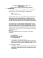
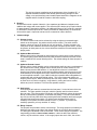
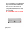
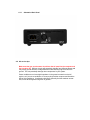
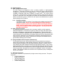
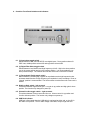
Empirical Audio
Overdrive SE DAC
User Manual
© 2012
Overdrive® SE DAC User Manual
Empirical Audio Rev. 1.0
Critical – read all red warnings first to prevent equipment damage
1. Technology/Design
The Overdrive DAC incorporates our excellent low-jitter USB interface technology and
breaks new ground for D/A converter technology. The Overdrive design philosophy is
“less is more”, with one of the simplest analog paths ever devised. The Overdrive
provides solutions for the three most important issues with digital sources:
•
•
•
Jitter
D/A noise/distortion
Volume control noise/distortion
This high-performance triple solution is unprecedented and delivers a totally new sound
quality level. The Overdrive is a non-upsampling DAC (no ASRC) that has an ultrasimple analog signal path, reducing background noise and harmonic distortion to
unprecedented levels. It incorporates a preamp function that has never been tried in
ANY audio product before. This preamp function adds no devices whatsoever to the
signal path, leaving it simple and ultra-low noise. It has selectable digital filters that allow
one to tailor the sound to your personal taste. You can effectively eliminate them if you
want.
The sound of the Overdrive is simply indescribable and utterly magical. The clarity is
unlike anything you have heard before, particularly driving amps directly. Other DACs
sound muddy in comparison. The bass is tight and the detail and imaging is more than
first-rate, it’s breathtaking. Drums are rendered with more realism than any other DAC is
capable of. The leading and trailing edges and harmonics of percussion, strings and
woodwinds are delivered with true realism. Even with this level of detail and dynamics, it
still gets vocals right. The Overdrive USB DAC resets the bar for the term “accuracy” in
digital to analog conversion.
1.1. Performance
The performance of the Overdrive DAC is a result of several innovative design
breakthroughs:
1.
2.
3.
4.
5.
6.
Low jitter USB interface module
Ultra-Simple pure Class-A analog Path
D/A Volume Control
Ultra-Linear low-noise Output Stage
Fully Balanced Analog Path
Selectable digital filters
1.1.1.
Low jitter Asynchronous USB interface module:
This asynchronous USB module is the same device that we use in our popular
Off-Ramp 5 USB converter. This is a 5th generation USB converter and rates #1
against all other converters on the market. The USB interface enables bit-perfect
playback from Mac and PC, supporting sample-rates up to 24/192.
1.1.2.
Ultra-Simple Analog Path:
The analog path consists of an I/V stage (ultra-low noise op-amp) driving a single
output transistor through a coupling cap. All stages are run Class-A, so it gets a
bit warm. There are no resistors at all in the analog signal paths, except for very
small necessary damping resistors on the output. Resistors add noise, so they
are best avoided.
1.1.3.
D/A Volume Control:
The revolutionary volume control is accomplished without any added parts to
the line-output signal path. It is not an entirely digital or entirely analog volume
control. It is a little of each actually. The volume is adjusted by changing the
reference voltage of the D/A conversion. It does NOT adjust attenuation of a
resistor divider, change the gain of an amplifier stage or truncate bits in the digital
data. All of these would add noise and/or distortion to the signal. This volume
technology actually reduces S/N ratio with lower volume.
1.1.4.
Ultra-Linear Output Stage:
The output stage is a single transistor in Class-A mode. It is well known that this
simple configuration results in some compression distortion, but also sounds
most natural. In order to effectively eliminate this compression distortion, we
incorporated a compensation circuit in the Overdrive. The output stage
impedance is low enough and the power output high enough to drive most highimpedance headphones easily, so we provide an adapter. It can drive either
normal or balanced headphones such as Sennheiser.
1.1.5.
Fully Balanced Analog Path:
There are 4 analog paths, all identical. They connect from the D/A converter chip
to the outputs. All 4 are used for the balanced outputs, 2 of the 4 are used for the
Single-Ended outputs. Resistors provide some isolation, so all outputs may be
used. We recommend low-capacitance interconnects if all 4 outputs are used,
and shorter is better. The output drive is sufficient for all preamps and amps, and
even high-impedance headphones like Sennheiser.
1.1.6.
Selectable Digital Filters:
A front panel switch selects 3 digital filter responses, low, medium and high. For
most DACs these are automatically selected, low for 44.1, medium for 96 and
high for 192. However, the Overdrive allows these to be selected manually in
order to improve audio quality. This makes the Overdrive closer to a NOS DAC.
For sample-rates of 176.4 and 192, the high position MUST BE SELECTED.
It is recommended that the high position be selected for all sample-rates,
however some users may find that some ultrasonics are audible at 44.1. For
these, the medium or low settings can be used. The settings do not engage until
the track is stopped and restarted.
1.2. Design Choices:
A number of design decisions were made in order to optimize performance and sound
quality over all other criteria:
1.2.1.
1.2.2.
1.2.3.
1.2.4.
Small Chassis size
This was critical to reducing both digital and analog signal path lengths. Long
signal paths add distortion due to circuit-board dielectrics and also introduce
more noise due to ground-plane coupling and crosstalk.
Op-Amp I/V conversion
This was necessary in order to optimize the loading of the D/A converter. Some
D/A chips require certain loading and voltage on their outputs in order to
guarantee best linearity and low-distortion.
AC-coupled output
This was chosen because the alternative of DC-coupling would not allow a pure
Class-A operation throughout, which delivers lower distortion. The coupling
capacitors available now are very close to a copper wire in performance.
Separate Substation AC chassis
This is a key element contributing to the performance of the Overdrive SE. A
separate Substation enables more densely packed energy storage for each
voltage, more optimized layout and creates space between the magnetics in the
supplies and the Overdrive Chassis to eliminate coupling.
2. Break-in
All electronics needs a period of break-in. New capacitors and dielectric insulators must
stabilize with voltage and current applied. The Overdrive SE is broken-in by Empirical Audio
for approximately 5 days before shipping. An additional 25 days of 24/7 break-in is required
for full break-in, with all inputs driven. Each input breaks-in independently, so all should be
driven with a signal. Outputs do not have to be connected in order to break-in.
3. Volume settings
3.1. Volume Control
The volume control mode can be selected by using the right-most recessed toggle
switch on the front panel. Up position selects volume control. The switch selects
between volume or line-out on power-up only, not on-the-fly. To make a change, you
must power off the Substation and back on using the front-panel power switch. As with
all systems, at initial power-on, the volume should be rotated to its lowest setting before
playing music.
3.2. Optimum Manual Control
Manual control can be optimized for performance if the volume knob is near maximum.
The internal gain jumpers behind the front panel should be selected so that the volume
knob is rotated 50% at normal listening levels. The default settings for these jumpers is
medium.
3.3. Optimum Remote Control
Remote volume control capability can be achieved quite easily by using a combination of
the manual volume control, a digital volume control (such as iTunes, Amarra or Pure
Music volume) and the USB interface. If one adjusts the volume to a comfortable
listening level with the manual control with the software digital control at max, then only
small reductions of the digital control from maximum are necessary to adjust the trackto-track amplitude variation. Up to –9dB of reduction is possible without degradation in
sound quality with a high-quality digital volume. This is even better than having yet
another remote control. Most of us already have too many of those. It allows you to use
an iPod Touch or iPad for everything: song selection, muting and volume control,
without any loss of resolution. This is the best possible scenario.
3.4. Gain Switch
A two-position gain switch is recessed into the front-panel. It is the left-most of the two
switches. The upper position is low-gain, which is typically used for volume control
direct to amps. The lower-position is high-gain, typically used with volume driving amps
directly to low-efficiency speakers, or line-level to a preamp. This can be switched at
any time, but will only take effect after powering down the Substation and back up again
using the front-panel power switch. For driving most amplifiers directly with 1V
sensitivity for full power, the switch should be in the “L” position. If you have lowsensitivity speakers, you may need the “H” setting.
3.5. Range Jumpers
Two jumpers are provided to set the volume range. The range jumpers are located just
inside the front panel to the right of the volume control as you look at the front panel.
The settings are illustrated on the circuit board. Three volume ranges are possible. The
range setting provides a lower volume extreme. It does not affect the maximum
volume, only the minimum volume. If the range jumpers are set for “Min”, the volume
will have the least range, so the lowest volume will still be loud. If the range jumpers are
set for “Max”, the volume control when at the minimum will be very quiet. This allows the
volume to be tailored so that a fairly wide arc can be used in adjustment for track-totrack amplitude variation.
The default factory setting is “Medium”. Make sure the Overdrive is powered-off for this
adjustment. The front panel and knob must be removed to access these.
4. Substation AC
The Substation provides three DC voltages to the Overdrive, +12VDC, +18VDC and –
18VDC. In standby mode, all voltages are powered in the Substation AC, but there is no
DC output. The three red LEDs should be on when the power cord is attached. The
Substation AC provides power sequencing to the Overdrive SE, so it should always be
powered using the front panel switch.
Danger: never connect the Umbilical to the Overdrive with the Substation power
on.
4.1. Substation Front Panel
The red LED indicators are:
top
+12VDC
Middle –18VDC
Bottom +18VDC
4.1.1.
Substation Back Panel
4.2. AC service tips
Make sure that you use the same circuit from the AC panel for the computer and
the Overdrive SE. Different circuits will potentially originate from different phases and
may cause ground reference voltage differences with resulting high-currents in the
ground. This can potentially damage other components in your system.
Power conditioners can have high-impedance in the ground connection to the AC
service, so if you use a conditioner, it is best to plug both the computer and Overdrive
SE into this conditioner. Conditioners with filters generally limit the transient currentflow, so we advise against using them in general.
5. Overdrive Back Panel Connectors
5.1. Digital Inputs
5.1.1.
I2S input
The Overdrive I2S input is compatible with the Empirical Audio I2S standard. It
can be driven with a Pace-Car or an Off-Ramp. It supports up to 24/192.
5.1.2.
S/PDIF coax input
The S/PDIF coax digital input can be driven from any audio device with digital
output conforming to the S/PDIF standard IEC-60958. The input impedance is
75 ohms. It is recommended that stock transports and devices other than that
manufactured by Empirical Audio use a 1.5m minimum 75 ohm digital cable in
order to minimize the jitter caused by reflections. Devices manufactured by
Empirical Audio can use a 1m 75 ohm digital cable length.
5.1.3.
USB input
The USB input can be driven with a 5m (16-foot) USB cable from any USB2.0
port on a computer. The USB port supports up to 24/192 sample-rate and uses a
custom software driver for each OS version of Windows or Mac.
5.2. Analog Outputs
5.3. RCA – Single-ended outputs
The RCA outputs are designed to drive a preamp, amplifier or high-impedance
headphones. These are AC-coupled, so there is a delay in the power output from them
on power-on in order that the DC voltage settle-out. The line output level from these is
2.3VRMS in high-gain mode and 1.0VRMS in low-gain mode. The volume control
reduces this. On power-down, the outputs disconnect from the output drivers and short
to ground. When there is no valid signal, the outputs are disconnected from the output
drivers and shorted to ground. When active, the outputs can withstand short to ground
without damage to the Overdrive.
5.3.1.
Headphone adapter
A headphone adapter is provided. The red plug on the adapter goes into the left
channel RCA output. Never use standard Headphones and the balanced
outputs to speaker system at the same time without selecting the RCA out
Buffer - this may cause system or speaker damage. Also avoid high static
charge on the headphone cable when plugging it in. Ground yourself and
the cable contacts first.
5.4. XLR – Balanced outputs
The balanced outputs are designed to drive a preamp, amplifier or high-impedance
balanced headphones. These are AC-coupled, so there is a delay in the power output
from them on power-on in order that the DC voltage settle-out. The line output level
from these is 4.6VRMS in high-gain mode and 2.0VRMS in low-gain mode. The volume
control reduces this. On power-down, the outputs disconnect from the output drivers and
short to ground. When there is no valid signal, the outputs are disconnected from the
output drivers and shorted to ground. When active, the outputs can withstand short to
ground without damage to the Overdrive.
5.5. Using both RCA and XLR outputs simultaneously
For best performance, this is best avoided, however this is sometimes necessary in
order to drive a subwoofer or other ancillary electronics. Each of the 4 output drivers is
shared between the balanced XLR and single-ended RCA outputs. However, there is
some isolation with small resistance between the XLR and RCA outputs. If one uses all
outputs simultaneously to a system, it is recommended that either the XLR cables or the
RCA cables be short and low-capacitance and drive a high impedance buffer or preamp.
If this is not possible, then switch the recessed “Normal/Bypass” switch to the Bypass
position. This causes the RCA outs to be driven from a separate Op-amp, isolating them
from the XLR outputs.
5.6. DC Power Connector
The DC power connector is a professional 5-pin high-current locking connector. The power
inputs are:
• +12VDC Digital Power
• Digital Ground/Return
• -18VDC Analog Power
• Analog Ground/Return
• +18VDC Analog Power
6. Overdrive Front Panel Switches and Indicators
6.1. (3) Input select toggle switch
Selects between USB, I2S and S/PDIF coax digital inputs. Down position selects S/
PDIF coax, middle position selects I2S and up position selects USB.
6.2. (2) Digital Filter Select toggle switch
Selects between Low, Medium and High frequency roll-offs. High is the down position,
Low is the center position and up is the medium position. It is recommended to use
down position always. The function does not take effect until a new track is started.
6.3. (1) De-emphasis Enable toggle switch
When enabled by switching up, it applies an equalization at the high-frequencies that
eliminates harshness due to high-frequency pre-emphasis in some recordings. Down or
“Normal” position is recommended. The function does not take effect until a new track is
started.
6.4. High/Low Gain switch – left recessed
This selects between high and low gain. Low gain is up position and high gain is down
position. The function only changes on power-up.
6.5. Volume/Line-Out toggle switch – right recessed
This selects between volume control and line-out. Volume control is up position and
Line Out is down position. The function only changes on power-up.
6.6. USB Fault Indicator
USB fault is illuminated when the USB cable is unplugged at either end, or the +5V in
the cable is not present. The 5V cable voltage is not used, except to light the LED.
6.7. Data Error Indicator
Illuminated indicates that there is no valid data coming in on the selected digital input.
6.8. DC Power Indicator
Indicates that DC power is applied to the DC input connector.
7. Software
Software drivers must be loaded to support the USB interface for both PC and Mac before
connecting the USB cable. For operation on a PC, Kernel Streaming is recommended to
bypass Kmixer on XP machines and WASAPI on Vista and Win7 machines.
7.1. USB Drivers
Drivers are located on the included CDROM disk. Load the appropriate driver for your
machine and OS and execute it on the computer before powering the Off-Ramp 4 or
connecting the USB cable to the computer for the first time.
7.2. Player Software
For PC, the latest version of Foobar2000 is recommended as a player. Install this first.
For XP, a Kernel Streaming plug-in is included on the CDROM. Copy this plug-in to the
“components” folder under C:\Program Files\Foobar2000. Then start Foobar2000 and
select the File pull-down. Then select Preferences. In the Preferences window, go to
Playback – Output – select HiFace Kernel Streaming or Empirical Audio async 192.
With XP, the sample-rate will be selected automatically. With Vista and Win7, you must
change the sample-rate manually on the computer in control-panel/sounds and audio
devices/advanced, unless you are using Amarra, Pure Music or Ayrewave.
For Mac, we recommend iTunes with software add-ons such as Amarra, Pure Music, or
Ayrewave to improve audio quality and eliminated manual intervention to select samplerates.
If you use iTunes alone, then select HiFace or Empirical AudioAsync 192 in Preferences/
Audio and use Utilities/Midi options to select the sample-rate. Using iTunes alone
requires you to manually select the sample-rate each time you change to playback of a
different sample-rate.
8. Quick Start-up
8.1. Mac
• Put the supplied CDROM into your Mac and find the Mac driver folder.
• Open the folder and copy the driver software to your Mac hard disk for your OS.
• Execute the file and then execute the container (cardboard box ICON)
• The install will start and one of the steps will ask you for your password
• Power-on the Off-Ramp and connect the USB cable to the Mac and S/PDIF
digital coax cable to the DAC.
• Power on the DAC.
• Check in the Perferences/Sounds that you have Empirical Audio async 192
selected for output
• Start your music player application
• Check that both the red and yellow LEDs are off on the Off-Ramp
• Play a track or playlist using your player application
8.2. PC
•
•
•
•
•
•
•
•
Put the supplied CDROM into your PC and find the PC driver folder.
Open the folder and copy all of the files for your OS to your C: hard disk.
Execute the .exe file and follow the instructions.
Power-on the Off-Ramp and connect the USB cable to a USB 2.0 port on your
PC and S/PDIF digital coax cable to the DAC.
Power on the DAC.
Check in the Control Panel/Sounds and audio devices that you have HiFace or
Empirical Audio async 192 selected for output
Install Kernel Streaming in your player application
Start your music player application
•
•
•
Select HiFace Kernel Streaming or Empirical Audio 192 async Kernel Streaming
for output
Check that both the red and yellow LEDs are off on the Off-Ramp
Play a track or playlist using your player application
9. Specifications:
Inputs:
1. USB 2.0 or 3.0, Mac or PC, up to 5 meter USB cable – up to 24/192 supported
2. S/PDIF coax – Canare 75 ohm BNC - up to 24/192 supported
3. I2S (Empirical standard RJ-45) – up to 24/192 supported
4. DC power (+12VDC, -18VDC, +18VDC) from included Substation
Outputs:
1. RCA left and right channels
2. XLR left and right channels
Controls:
1. Input Select
2. De-emphasis Select
3. Digital Filter Select – High, Medium, Low
4. Line/Volume Select
5. Volume knob
6. Internal jumpers for 3 volume ranges and two gain settings
Electrical:
1. RCA output Level – 1VRMS or 2.3VRMS, XLR output level – 2VRMS or 4.6VRMS
2. Frequency response – 20-20kHz +/-0.5dB
3. Output impedance – each channel 40 ohms
Included:
1. Overdrive DAC
2. Substation DC power supply – over 60,000uFd of energy storage
3. DC power supply umbilical cable
4. 5 meter USB cable
5. 3 AC adapter power supplies
6. CDROM with PC and Mac installation software
7. RCA to Phone-jack Headphone adapter – only high-impedance headphones supported
Specifications are subject to change without notice.
© 2012 Empirical Audio all rights reserved.