1
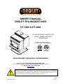
OWNER`S MANUAL
DROLET EPA WOODSTOVES
HT-1600 & HT-2000
US ENVIRONMENTAL PROTECTION
AGENCY PHASE II CERTIFIED
WOODSTOVES
Vérified and/or tested following
ULC S627 et UL 1482 Standards by:
READ AND KEEP THIS MANUAL FOR REFERENCE
Manufactured by: STOVE BUILDER INTERNATIONAL INC.
250, rue de Copenhague, Saint-Augustin-de-Desmaures (Quebec) G3A 2H3
Tel.: 418 878-3040 Fax: 418 878-3001
www.drolet.ca
This manual is available for free download on the manufacturer’s web site. It is a copyrighted document. Re‐sale is strictly prohibited. The manufacturer may update this manual from time to time and cannot be responsible for problems, injuries, or damages arising out of the use of information contained in any manual obtained from unauthorized sources. Printed in Canada
45060A
16-12-2011
TABLE OF CONTENTS
INTRODUCTION ....................................................................................................................3 TECHNICAL SPECIFICATIONS ............................................................................................4 TIPS ON WOOD HEATING ....................................................................................................5 ASSEMBLY ............................................................................................................................6 PEDESTAL AND DECORATIVE SIDEWALL INSTALLATION .................................................6 BRICKS AND INSULATION INSTALLATION (HT-1600) ...........................................................7 BRICK AND INSULATION INSTALLATION (HT-2000) .............................................................8 AIR TUBES INSTALLATION (HT-2000): .......................................................................................9 DOOR ADJUSTMENT ....................................................................................................................10 THE BENEFITS OF INSTALLING A BLOWER ....................................................................11 INSTALLATION ....................................................................................................................12 POSITIONING THE STOVE ...........................................................................................................12 CLEARANCES TO COMBUSTIBLES AND FLOOR PROTECTOR ...........................................13 CHIMNEY ........................................................................................................................................20 CHIMNEY CONNECTOR (STOVE PIPE) .....................................................................................21 DRAFT ..............................................................................................................................................23 TYPICAL INSTALLATIONS ..........................................................................................................24 WOODSTOVE UTILIZATION ...............................................................................................28 TESTING YOUR WOOD.................................................................................................................29 THE FIRST FIRES ...........................................................................................................................29 IGNITION .........................................................................................................................................29 HEATING .........................................................................................................................................30 RELOADING....................................................................................................................................31 CREOSOTE FORMATION AND NEED FOR REMOVAL ...........................................................31 ASH DISPOSAL ...............................................................................................................................32 MAINTENANCE ...................................................................................................................33 GLASS ..............................................................................................................................................33 GASKETING ....................................................................................................................................33 PAINT ...............................................................................................................................................33 DROLET LIMITED LIFETIME WARRANTY .........................................................................34 REGISTER YOU WARRANTY ONLINE
To receive full warranty coverage, you will need to show evidence
of the date you purchased your stove. Keep your sales invoice.
We also recommend that you register your warranty online at
http://www.drolet.ca/en/service-support/warranty-registration
Registering your warranty online will help us track rapidly the
information we need on your stove.
2
INTRODUCTION
SBI INC., one of the most important wood stove and fireplace manufacturers in Canada,
congratulates you on your purchase and wishes to help you get maximum satisfaction from
your wood stove. In the pages that follow, we will give you advice on wood heating and
controlled combustion as well as technical specifications regarding installation, operation
and maintenance of the model you have chosen.
The instructions pertaining to the installation of your wood stove comply with ULC-S627 and
UL-1482 standards.
We recommend that our wood burning hearth products be installed and serviced by
professionals who are certified in the United States by NFI (National Fireplace Institute®) or
in Canada by WETT (Wood Energy Technical Training) or in Quebec by APC (Association
des Professionnels du Chauffage).
Read this entire manual before you install and use your new stove. If this stove is not
properly installed, a house fire may result. To reduce the risk of fire, follow the
installation instructions. Failure to follow instructions may result in property
damage, bodily injury, or even death.
Consult your municipal building department or fire officials about restrictions and
installations requirements in your area and the need to obtain a permit.
Keep this instructions manual for future references.
CAUTIONS:
THE INFORMATION
GIVEN ON THE CERTIFICATION LABEL AFFIXED TO THE APPLIANCE ALWAYS
OVERRIDES THE INFORMATION PUBLISHED, IN ANY OTHER MEDIA (OWNER’S MANUAL,
CATALOGUES, FLYERS, MAGAZINES AND/OR WEB SITES).
HOT WHILE IN OPERATION. KEEP CHILDREN, CLOTHING AND FURNITURE AWAY. CONTACT MAY
CAUSE SKIN BURNS.
DO NOT USE CHEMICALS OR FLUIDS TO IGNITE THE FIRE.
DO NOT LEAVE THE STOVE UNATTENDED WHEN THE DOOR IS SLIGHTLY OPENED.
DO NOT BURN WASTES, FLAMMABLE FLUID SUCH AS GASOLINE, NAPHTHA OR MOTOR OIL.
DO NOT CONNECT TO ANY AIR DISTRIBUTION DUCT OR SYSTEM.
ALWAYS CLOSE THE DOOR AFTER THE IGNITION.
3
TECHNICAL SPECIFICATIONS
HT-1600
HT-2000
Wood
Combustion Type:
Recommended Surface
Heating Capacity* :
Wood
2
E.P.A :
Real :
Optimum Efficiency :
Average Emission:
Colour :
Flue Pipe Diameter :
Chimney type :
Maximum :
Continuous :
Minimum Chimney Height :
Maximum Log Length :
Dimensions
Overall:
On Pedestal Model :
Combustion Chamber :
Width x Depth :
Volume :
Door Opening :
Width x Height :
Pyroceram Glass Door :
Width x Height :
Mass:
900 to 1 800 ft
40 000 BTU/h
70 000 BTU/h
76%
3,5 g/h
Metallic Black
6’’ (152 mm)
2 100°F (1150°C)
1 200°F (650°C)
12’ (3,66 m)
18’’ (457 mm)
1 000 to 2 400 ft2
60 200 BTU/h
95 000 BTU/h
78%
3,9 g/h
Metallic Black
6’’ (152 mm)
2 100°F (1150°C)
1 200°F (650°C)
12’ (3,66 m)
22’’ (558 mm)
WxDxH
WxDxH
25 1/8 x 26 ½ x 33 1/4" 28 1/8 x 29 3/8 x 34 3/8"
(638 x 673 x 844mm)
(714 x 746 x 873 mm)
18 ¼ x 17 ¼"
(464 x 438 mm)
2,5 pi3 (0,07 m3)
22 7/8 x 20 5/8"
(581 x 524 mm)
3,4 pi3 (0,09 m3)
16 ¾ x 8 ¾"
(416 x 222 mm)
17 7/8 x 8 7/8"
(454 x 225 mm)
16 3/8 x 9 5/8’’
(416 x 244 mm)
420 lbs (190 Kg)
16 3/8 x 9 5/8"
(416 x 244 mm)
550 lb (249 Kg)
Yes
Yes
Yes
Yes
OPTIONS
Blower 75 CFM (2,83 m3/min) with
variable speed control
Thermodisc 100-120oF (37-490C).
*Why is the BTU indicated on the EPA label smaller than the one advertised?
You will notice a difference between the BTU output as indicated on the unit’s white EPA label affixed to the glass and
the BTU as advertised on our web site and/or product literature. The maximum BTU output we advertise for this unit is
what will be obtained with a full load of seasoned cordwood inserted inside the firebox. The EPA output, on the other
hand, is what has been obtained during emissions testing. The EPA test procedure requires that a special type of wood
be used and positioned inside the firebox in a manner that does not represent the way the firebox volume would normally
be utilized using seasoned cordwood. The EPA test load is typically much smaller. Hence, the BTU as per the EPA label
is reduced. The BTU output that should be considered by a normal user is the one we advertise for seasoned cordwood.
4
TIPS ON WOOD HEATING
Wood is a renewable energy. It is also a very clean heat source when used with
appliances that are certified by the U.S. Environmental Protection Agency (EPA), a
standard accepted in Canada as well.
EPA-certified wood stoves are different than conventional wood stoves. Burning with an
EPA-certified wood stove may therefore require that you modify some of your heating
habits. To get the most satisfaction out of your new wood-heating system, please make sure
you go through the following check list.
The chimney is the engine that drives the wood-heating system. Use a chimney that
is UL-listed, with an inner diameter to match the stove’s outlet collar (6” for all Drolet
wood stoves);
Try to run the chimney inside the building for as much length as you can. A tall and
warm chimney will produce a good draft;
Try to install your chimney straight up and avoid 90 degree turns in the flue pipe and
offsets in the chimney;
Make sure that the chimney is tall enough and its top is clear of obstacles so it can
produce a stable draft;
Use a chimney thermometer installed at a distance of approximately 18 inches on the
flue pipe above the stove. Flue gases should reach at least 350oF before you close
the stove’s primary air intake completely. Operate your unit within the comfort zone
indicated on the thermometer;
To reduce the risk of smoke spillage into the room upon reloading your stove, leave
the primary air intake completely open for a few minutes. This will heat up the
chimney and build up draft before you open the stove door;
Maximize hot air circulation! Our wood stoves are designed to easily receive a
variable speed blower that will improve heat distribution in front of the stove;
Remember that wood stoves produce radiant heat. Since heat rises, the use of floor
traps will greatly improve the heat transfer to rooms upstairs;
Use a mobile home approved stove if you are going to install your wood-heating
system in a mobile home. A fresh air kit must be connected to the stove. Never install
your wood stove in a bedroom;
Burn only dry cordwood;
Make sure you have a good bed of red coals before you load your stove with logs
exceeding 3 inches in diameter;
Read and keep you owner’s manual. It will provide you with tips on how to run a
successful wood-heating system.
5
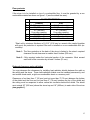
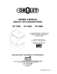
ASSEMBLY
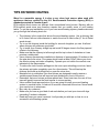
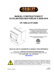
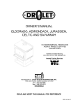
PEDESTAL AND DECORATIVE SIDEWALL INSTALLATION
Pedestal Installation :
1. Remove all bricks and insulations in
the appliance.
2. Slowly, lay down the stove on his
back.
3. Install legs or the pedestal with the
supplied nuts and bolts. Stand up
the stove and place it with the
required clearances.
Note that
there is eight holes in the bottom of
the stove but only four will align with
the pedestal.
4. Slide the front part of the pedestal
base around the pedestal and fix
the rear part with the two supplied
screws.
5. Slide the ash pan in position
Figure 1: HT-2000
6
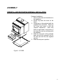
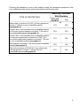
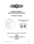
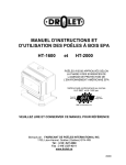
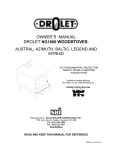
BRICKS AND INSULATION INSTALLATION (HT-1600)
1.
2.
3.
4.
5.
6.
7.
Remove from the stove all bricks and insulation.
Install all side bricks (11 x 4 1/2" x 9" & 1 x 4 ½” x 8 3/16") as shown in drawing below.
Install the back bricks (6 x 4 1/2" x 9")
Install the bottom bricks (4 x 4 1/2" x 9") + (2 x 6 " x 8") and the ash cap.
Install the "T" shape support.
Install the baffle bricks (4 x 4 1/2" x 9") + (2 x 3" x 9") on T shape support.
Finally, gently slide the insulation panels over the baffle bricks.
Nbr.
1
2
3
4
5
6
7
Description
1 ¼” x 4 ½” x 9”
1 ¼” x 4 ½” x 8 3/16"
1 ¼” x 6” x 7"
ASH CAP (SE09224)
1 ¼” x 3” x 9"
ISOLATOR (9 ½" x 12" )
SUPPORT (SE09242)
Qty
25
1
2
1
2
2
1
Figure 2: HT-1600 Refractory Bricks Assembly
7
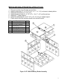
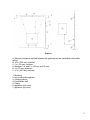
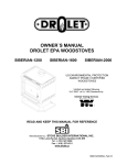
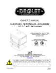
BRICK AND INSULATION INSTALLATION (HT-2000)
The stove is normally supplied with secondary air tubes in position. To install the baffle bricks
and white ceramic insulation, it’s necessary to remove the two front secondary air tubes. First
place only one baffle brick and one white ceramic insulation. Use the same method to put the
other baffle brick and insulation. Put back in place the secondary air tubes.
Install the yellow insulation and the 6" x 8" or 6" x 6" bricks. Install the side and bottom bricks.
Figure 3: HT-2000 Refractory Bricks Assembly
The baffle on the left is not positionned correctly. The baffle on the right is positionned perfectly. It
must be ontop of the bricks and at the rear of the unit.
8
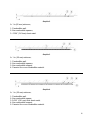
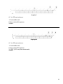
AIR TUBES INSTALLATION (HT-2000):
The secondary air tubes are painted different colours . The back tube is yellow, the middle
on is red and the front is unpainted. Before installing, make sure the locating holes in the
tubes (holes near one end of the tube) are on the left side. Insert one tube in the right side
air channel and slide it to the right as much as possible. Bring the left end of the tube aligned
with the ring welded to the left air channel. Move the tube to the left until the locating holes
are aligned with those in the ring. Insert a cutter pin to hold in place. The air injection holes
should be facing down in the front and middle tubes.
Figure 4: Air Tubes Installation
9
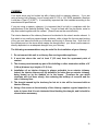
DOOR ADJUSTMENT
In order for your stove to operate properly, the door should be adjusted periodically to
provide an air tight fit. To adjust:
Remove the lock pin (spring pin) by pulling and turning it using pliers ("wise grip")
Turn the handle counter clock wise one turn to increase pressure
Re-install the lock pin (spring pin) with a small hammer
Figure 5: Door Adjustment
10
THE BENEFITS OF INSTALLING A BLOWER
A blower can be installed at the back of your DROLET stove. This option is necessary if you
wish to redistribute into a room the heat trapped at the back of your stove. By forcing hot air
toward the front, the blower enables you to extend the radiation power of your stove.
You can purchase this option through your DROLET dealer. Make sure to specify this part
number: #AC02050. You can also install a thermodisc to enable the blower to start or stop
automatically when the stove is hot or too cold. The thermodisc part number is AC05530.
Installation instructions are supplied with the blower and the thermodisc.
11
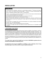
INSTALLATION
SAFETY NOTICE
IF THIS STOVE IS NOT PROPERLY INSTALLED, A HOUSE FIRE MAY RESULT. TO REDUCE THE RISK OF
FIRE, FOLLOW THE INSTALLATION INSTRUCTIONS. FAILURE TO FOLLOW INSTRUCTIONS MAY
RESULT IN PROPERTY DAMAGE, BODILY INJURY, OR EVEN DEATH.
CONSULT YOUR MUNICIPAL BUILDING DEPARTMENT OR FIRE OFFICIALS ABOUT RESTRICTIONS AND
INSTALLATIONS REQUIREMENTS IN YOUR AREA.
USE SMOKE DETECTORS IN THE ROOM WHERE YOUR STOVE IS INSTALLED.
KEEP FURNITURE AND DRAPES WELL AWAY FROM THE STOVE.
NEVER USE GASOLINE, GASOLINE-TYPE LANTERN FUEL, KEROSENE, CHARCOAL LIGHTER FLUID, OR
SIMILAR LIQUIDS TO START OR "FRESHEN UP" A FIRE. KEEP ALL SUCH LIQUIDS WELL AWAY FROM
THE STOVE.
IN THE EVENT OF A CHIMNEY FIRE, PUSH THE AIR CONTROL FULL CLOSED TO DEPRIVE THE FIRE OF
OXYGEN. CALL THE FIRE DEPARTMENT.
DO NOT CONNECT TO ANY AIR DISTRIBUTION DUCT OR SYSTEM.
A SOURCE OF FRESH AIR INTO THE ROOM OR SPACE HEATED SHALL BE PROVIDED WHEN
REQUIRED.
POSITIONING THE STOVE
It is very important to position the wood stove as close as possible to the chimney, and in an
area that will favour the most efficient heat distribution possible throughout the house. The
stove must therefore be installed in the room where the most time is spent, and in the most
spacious room possible. Recall that wood stoves produce radiating heat, the heat we feel
when we are close to a wood stove. A wood stove also functions by convection, that is
through the displacement of hot air accelerated upwards and its replacement with cooler air.
If necessary, the hot air distribution from the stove may be facilitated by the installation of a
blower.
The wood stove must not be hooked up to a hot air distribution system since an
excessive accumulation of heat may occur.
A wood stove must never be installed in a hallway or near a staircase, since it may
block the way in case of fire or fall to respect required clearances.
12
CLEARANCES TO COMBUSTIBLES AND FLOOR PROTECTOR
To install your appliance correctly, it is extremely important to respect all clearances to any
combustibles as indicated on your stove’s certification label.
Clearances to combustible materials
(see figure 1.3 to match each letter to a clearance)
CLEARANCES (SINGLE WALL PIPE)
CANADA / USA
MODEL
A
B
C
D
E
F
K
L
HT-1600
15’’
16’’
12’’
18’’
26’’
24’’
(385 mm) (410 mm) (305 mm) (460 mm) (665 mm) (610 mm)
48’’
(1220
mm)
84’’
(213 cm)
HT-2000
19’’
19’’
11’’
23’’
30’’
23’’
(485 mm) (485 mm) (280 mm) (585 mm) (765 mm) (585 mm)
48’’
(1220
mm)
84’’
(213 cm)
K
L
CLEARANCES (DOUBLE WALL PIPE)
CANADA / USA
MODEL
A
B
C
D
E
F
HT-1600
12’’
16’’
10’’
15’’
26’’
22’’
(305 mm) (410 mm) (255 mm) (385 mm) (665 mm) (560 mm)
48’’
(1220
mm)
84’’
(213 cm)
HT-2000
10’’
14’’
8’’
14’’
25’’
20’’
(255 mm) (360 mm) (205 mm) (360 mm) (635 mm) (510 mm)
48’’
(1220
mm)
84’’
(213 cm)
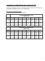
13
FIGURE 1.3 Clearances to combustible materials and floor protection
14
Floor protector
If the stove is to be installed on top of a combustible floor, it must be guarded by a non
combustible material as shown on figure 1.3 (see the dotted line area).
FLOOR PROTECTOR*
G
H
I
J
M
N
CANADA
8’’ (205 mm) – Note 1
8’’ (205 mm)
18’’ (460 mm)
From door opening
N/A (USA only)
8’’ (205 mm)
N/A (USA only)
USA
N/A (Canada only)
N/A (Canada only)
16’’ (410 mm)
From door opening
8’’ (205 mm)
N/A (Canada only)
Note 2
*Steel with a minimum thickness of 0.015’’ (0.38 mm) or ceramic tiles sealed together
with grout. No protection is required if the unit is installed on a non-combustible floor (ex:
concrete).
Note 1 : The floor protection at the back of the stove is limited to the stove’s required
clearance if such clearance is smaller than 8 inches (205 mm).
Note 2 : Only required under the horizontal section of the connector. Must exceed
each side of the connector by at least 2 inches (51 mm).
Reduced clearances using shielding
You may decrease the clearances by installing heat radiation shields between the walls or
the ceiling and the stove. These heat radiation shields must be installed permanently, and
can include sheet metal, a rigid non-combustible sheet or a masonry wall.
Clearances of not less than 1" (25 mm) and not more than 3" (76 mm) between the bottom
of the shield and the floor and not less than 3" (76 mm) between the top of the shield and
the ceiling must be respected to allow vertical air circulation behind the shield. The shield
must extend 20" (500 mm) above the stove top and 18" (450mm) to each side of the stove
(see graphic 1).
15
Following the installation of such a heat radiation shield, the clearances mentioned on the
stove certification plate may be reduced as stated in the following table.
TYPE OF PROTECTION
Reducing Clearances
With Shielding
Sides and
Rear/Back
Top
Sheet metal, a minimum of 0,024" (0,61mm) spaced out
at least 1" (25mm) by non-combustible spacers
(see graphic 2).
67%
50%
Ceramic tiles, or an equivalent non-combustible material
on fire-proof supports spaced out at least 1" (25 mm) by
non-combustible spacers (see graphic 3).
50%
33%
Ceramic tiles, or an equivalent non-combustible material
on fire-proof supports with a minimum of 0,024" (0,61
mm) sheet metal backing spaced out at least 1" (25 mm)
by non-combustible spacers (see graphic 4)
67%
50%
Brick spaced out at least 1" (25 mm) by non-combustible
spacers (see graphic 5)
50%
N/A
Brick with a minimum of 0,024" (0,61 mm) sheet metal
backing spaced out at least 1" (25 mm) by noncombustible spacers (see graphic 6).
67%
N/A
16
Graphic 1
A- Minimum clearance required between the appliance and an unshielded combustible
ceiling.
B- 20 in. (500 mm) minimum;
C- 1 in. (25 mm) minimum;
D- Between 1 in. and 3 in. (25 mm and 75 mm);
E- 3 in.(75 mm) minimum;
F- 18 in. (457 mm) minimum.
1- Shielding;
2- Non-combustible spacers;
3- Ceiling protector;
4- Combustible wall;
5- Ceiling;
6- Appliance (side view);
7- Appliance (top view).
17
Graphic 2
A- 1 in.(25 mm) minimum;
1- Combustible wall;
2- Non-combustible spacers;
3- 0.024’’ (0.61mm) sheet metal.
Graphic 3
A- 1 in. (25 mm) minimum;
1- Combustible wall;
2- Non-combustible spacers;
3- Non-combustible support;
4- Ceramic tile or non-combustible material.
Graphic 4
A- 1 in. (25 mm) minimum;
1- Combustible wall;
2- Non-combustible spacer;
3- 0.024’’ (0.61 mm) thick sheet metal;
4- Non-combustible support;
5- Ceramic tile or non-combustible material.
18
Graphic 5
A- 1 in. (25 mm) minimum;
1- Combustible wall;
2- Non-combustible spacers;
3- Brick.
Graphique 6
A- 1 in. (25 mm) minimum;
1- Combustible wall;
2- Non-combustible spacers;
3- 0.024’’ (0.61 mm) thick sheet metal;
4- Brick.
19
CHIMNEY
Your wood stove may be hooked up with a factory built or masonry chimney. If you are
using a factory built chimney, it must comply with UL 103 or ULC S629 standards; therefore
it must be a Type HT (2100°F). It is extremely important that it be installed according to the
manufacturer's specifications.
If you are using a masonry chimney, it is important that it be built in compliance with the
specifications of the National Building Code. It must be lined with fire clay bricks, metal or
clay tiles sealed together with fire cement. (Round flues are the most efficient).
The interior diameter of the chimney flues must be identical to the stove's smoke exhaust. A
flue which is too small may cause draught problems, while a large flue favours rapid cooling
of the gas, and hence the build-up of creosote and the risk of chimney fires. Note that it is
the chimney and not the stove which creates the draught effect; your stove's performance is
directly dependent on an adequate draught from your chimney.
The following recommendations may be useful for the installation of your chimney:
1. Do not connect this unit to a chimney flue serving another appliance.
2. It must rise above the roof at least 3' (0.9 mm) from the uppermost point of
contact.
3. The chimney must exceed any part of the building or other obstruction within a 10'
(3.04 m) distance by a height of 2' (0.6 m).
4. Installation of an interior chimney is always preferable to an exterior chimney.
Indeed, the interior chimney will, by definition, be hotter than an exterior chimney,
being heated up by the ambient air in the house. Therefore the gas which
circulates will cool more slowly, thus reducing the build-up of creosote and the
risk of chimney fires.
5. The draught caused by the tendency for hot air to rise will be increased with an
interior chimney.
6. Using a fire screen at the extremity of the chimney requires regular inspection in
order to insure that it is not obstructed thus blocking the draught, and it should be
cleaned when necessary.
20
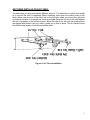
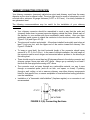
CHIMNEY CONNECTOR (STOVE PIPE)
Your chimney connector (commonly called stove pipe) and chimney must have the same
diameter as the stove’s exhaust outlet. The stove pipe must be made of aluminized or cold
roll steel with a minimum 24-gauge thickness (0.021" or 0.53 mm). It is strictly forbidden to
use galvanized steel.
The following recommendations may be useful for the installation of your chimney
connector:
Your chimney connector should be assembled in such a way that the male end
(crimped) faces down to prevent creosote dripping outside the joints. Attach each of
the sections to one another with three equidistant metal screws. Also use three
equidistant metal screws to attach the connector to the stove’s exhaust collar. See
Figure 2.3 (A) and Figure 2.3 (B).
The pipe must be short and straight. All sections installed horizontally must slope at
least ¼ inch per foot, with the upper end of the section toward the chimney. See
Figure 2.3 Detail B.
To insure a good draft, the total horizontal length of the connector should never
exceed 8' to 10' (2.4 to 3.04 m). In the case of vertical installation, the total length of
the connector can be much longer and connected without problem to the chimney at
the ceiling level.
There should never be more than two 90 degrees elbows in the whole connector and
chimney system. Never start with a 90o elbow. Always go up vertically for at least 2
feet from the flue spigot before using a 90o elbow.
The connector must not pass through any combustible material, nor may it pass
through a concealed space (such as an attic, roof space, or closet). If passing
through a wall, ceiling, or into a masonry chimney, use either chimney components
listed for that specific use, or means acceptable to local authorities having jurisdiction
over the installation.
Installation of a "barometric draft stabiliser" (fireplace register) on a connector is not
recommended.
FIGURE 2.3 (A) Connecting Sections
21
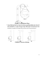
FIGURE 2.3 (B) Minimum Slope
The assembly should be as short and direct as possible between the stove and
chimney (See figure 2.4 (A)). The use of two 45 degree elbows (See figure 2.4 (C)) is
often preferable to a single 90 degree elbow (See figure 2.4 (B)) because less
turbulence is created in the exhaust flow and they result in less horizontal run.
(A)
(B)
(C)
FIGURE 2.4 The use of elbows
22
DRAFT
Your E.P.A Drolet stove’s performance will be optimised if it is installed with a chimney (flue)
system that provides an adequate draft. The draft is the force that moves air from the
appliance up through the chimney and is predominantly affected by the height and diameter
of the chimney, as well as the stack temperatures of the stove. If you test the draft using a
pressure gauge, the reading should be between .05 - .07 inches of water column (w.c.) at a
medium-high fire. A draft measure of less than .03" w.c. will cause operational difficulties
while too much draft (greater than .10" w.c.) will result in over-firing of the stove. This can
result in excessive operating temperatures. In this case, the installation of elbows totaling no
more than 180° (ex.: 2 x 30° elbows, 2 x 45° elbows or 2 x 90° elbows) can be installed to
help reduce excessive draft. If the addition of elbows is not sufficient, a manual damper can
be installed in the vertical flue pipe.
23
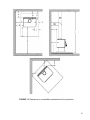
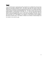
TYPICAL INSTALLATIONS
FACTORY BUILT CHIMNEY:
RAIN CAP
ROOF FLASHING
18" CLEARANCE
RADIATION SHIELD
WALL RADIATION SHIELD
WALL SUPPORT
CEILING SUPPORT
Wall installation
Vertical installation
24
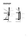
MASONRY CHIMNEY:
C lay liner
Thimb le
C lean out
door
25
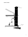
FACTORY BUILT THIMBLE:
26
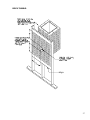
BRICK THIMBLE:
27
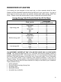
WOODSTOVE UTILIZATION
Your heating unit was designed to burn wood only; no other materials should be burnt.
Wastes and other flammable materials should not be burnt in your wood stove. Any type of
wood may be used in your stove, but specific varieties have better energy yields than
others. Please consult the following table in order to make the best possible choice.
Average Energy Yield Of One Air Dried Cord Of Cut Wood
Wood species
High energy yield
Medium energy yield
Low energy yield
Oak
Sugar Maple
Beech
Yellow birch
Ash
Elm
Larch (Tamarack)
Red Maple
Douglas red fir
Silver birch
Alder
Poplar
Hemlock
Spruce
Pine
Bass
Fir
Energy yield
(millions of BTU/cord)
29
28
26
25
24
23
23
23
23
22
18
17
17
17
17
16
13
Data provided by Energy, Mines and Resources - Canada
IT IS EXTREMELY IMPORTANT THAT YOU USE DRY WOOD ONLY IN YOUR WOOD
STOVE. The wood must have dried for 9 to 15 months, such that the humidity content (in
weight) is reduced below 20% of the weight of the log. It is very important to keep in mind
that even if the wood has been cut since one, two or even more years, it is not necessarily
dry, if it has been stored in poor conditions; under extreme conditions, it may even rot
instead of drying. The vast majority of the problems related to the operation of a wood stove
are caused by the fact that the wood used was too damp or had dried in poor conditions.
These problems can be:
ignition problems
creosote build-up causing chimney fires
low energy yield
blackened windows
incomplete log combustion
28
Smaller pieces of wood will dry faster. All logs exceeding 6" in diameter should be split.
The wood should not be stored directly on the ground. Air should circulate through the cord.
A 24" to 48" air space should be left between each row of logs, which should be placed in
the sunniest location possible. The upper layer of wood should be protected from the
element but not the sides.
TESTING YOUR WOOD
When the stove is thoroughly warmed, place one piece of split wood (about five inches in
diameter) parallel to the door on the bed of red embers.
Keep the air control fully open by pulling on it and close the door. If ignition of the piece is
accomplished within 90 seconds from the time if was placed in the stove, your wood is
correctly dried. If ignition takes longer, your wood is damp.
If your wood hisses and water or vapour escapes at the ends of the piece, your wood is
soaked or freshly cut. Do not use this wood in your stove. Large amounts of creosote could
be deposited in your chimney, creating potential conditions for a chimney fire.
THE FIRST FIRES
The fresh paint on your stove needs to be cured to preserve its quality. Once the fuel charge
is properly ignited, only burn small fires in your stove for the first four hours of operation.
Never open the air control more than necessary to achieve a medium burn rate.
Make sure that there’s enough air circulation while curing the stove. The odours could be
smelled during the 3 or 4 first fires. Never start your stove outside. You will not be able to
see if you are overheating.
IGNITION
After making sure that the stove air intake controls are fully open (completely pull-out
towards you), place several rumpled sheets of paper in the centre of the combustion
chamber. Place 8 to 10 pieces of small dry kindling wood over the paper in the form of a
tent. You may also place a few pieces of heating wood, but choose the smaller ones. No
chemical product should be used to light the fire.
Before igniting the paper and kindling wood, it is recommended that you warm up the
chimney. This is done in order to avoid back draft problems often due to negative pressure
in the house. If such is the case, open a window slightly near the stove and twist together a
few sheets of newspaper into a torch. Light up this paper torch and hold it as close as
possible to the mouth of the pipe inside the combustion chamber to warm up the chimney.
Once the updraft movement is initiated, you are ready to ignite the stove by lighting the
paper and kindling wood inside the combustion chamber.
We therefore advise you to leave the door slightly opened (1/4") for a 10 to 30 minutes
period, under supervision, in order to allow for good combustion. After this time, you must
close the door and progressively adjust the air control to obtain the desired temperature.
29
HEATING
Controlled combustion is the most efficient technique for wood heating because it enables
you to select the type of combustion you want for each given situation. The wood will burn
slowly if the wood stove air intake control is adjusted to reduce the oxygen supply in the
combustion chamber to a minimum. On the other hand, wood will burn quickly if the air
control is adjusted to admit a larger quantity of oxygen in the combustion chamber. The air
intake control on your stove is very simple. If you move it out completely towards the right, it
is fully open. If you move it towards the left until it stops the combustion air is reduced to a
minimum.
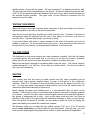
The following burn rates will be achieved according to control setting.
Burn rate
Model
HT-1600
Low
Medium
Medium high
High
full close
1/4"
5/8"
full open
HT-2000
full close
1/2"
1"
full open
HT-1600 Air control
OPENING
HT-2000 Air control
OPENING
Please note that the HT series stoves do not have the same operating range. The HT-1600
type stove burned between 0.93 and 3.32 kg/hr during EPA testing. The 2000 serie
achieved between 0.95 kg/h and 4.9 kg/h under the same conditions . Real operating
conditions may give very different results than those obtained in the lab according to the
species of wood used, its moisture content, the size and density of the pieces, the length of
the chimney, altitude, outside temperature.
Note regarding the HT1600 :
In order to achieve an optimum efficiency from your unit, we suggest that you operate it with
the air control slightly open (approximately 10%). Make sure that you have a good fire going
and an adequate ember bed before you completely close the air control. Use a chimney
thermometer if necessary. Closing the air control too soon will lower combustion efficiency
30
and may cause the fire to die out. The addition of a blower (if not already included) is highly
recommended to maximize your unit’s efficiency.
Note regarding the HT2000 :
In order to achieve an optimum efficiency from your unit, we suggest that you operate it with
the air control completely closed. Make sure that you have a good fire going and an
adequate ember bed before you completely close the air control. Use a chimney
thermometer if necessary. Closing the air control too soon will lower combustion efficiency
and may cause the fire to die out. The addition of a blower (if not already included) is highly
recommended to maximize your unit’s efficiency.
RELOADING
Once you have obtained a good bed of embers, you should reload the unit. In order to do
so, open the air controls to maximum a few seconds prior to opening the stove's door. Then
proceed by opening the door very slowly; open it one or two inches for 5 to 10 seconds,
before opening it completely to increase the draught and thus eliminate the smoke which is
stagnant in a state of slow combustion in the stove. Then bring the red embers to the front
of the stove and reload the unit.
For optimal operation of your wood stove, we recommend you operate it with a wood load
approximately equivalent to the height of fire bricks.
It is important to note that wood combustion consumes ambient oxygen in the room .In the
case of negative pressure, it is a good idea to allow fresh air in the room, either by opening
a window slightly or by installing a fresh air intake system on an outside wall. Refer to page
16 of the present manual.
WARNINGS
NEVER OVERFIRE YOUR STOVE. IF ANY PART OF THE STOVE STARTS TO GLOW RED, OVER FIRING
IS HAPPENING. READJUST THE AIR INTAKE CONTROL AT A LOWER SETTING.
THE INSTALLATION OF A LOG CRADLE IS NOT RECOMMENDED IN YOUR DROLET WOOD STOVE.
NEVER PUT WOOD ABOVE THE FIREBRICK LINING OF THE FIREBOX.
CREOSOTE FORMATION AND NEED FOR REMOVAL
When wood is burned slowly, it produces tar and other organic vapours, which combine with
expelled moisture to form creosote. The creosote vapours condense in the relatively cool
chimney flue of a slow-burning fire. As a result, creosote residue accumulates on the flue
lining. When ignited this creosote makes an extremely hot fire. When burning wood, the
chimney connector and chimney should be inspected at least once every two months during
the heating season to determine if a creosote build-up has occurred.
We strongly recommend that you install a magnetic thermometer on your smoke exhaust
pipe, approximately 18" above the stove. This thermometer will indicate the temperature of
your gas exhaust fumes within the smoke exhaust system. The ideal temperature for these
31
gases is somewhere between 275o F and 500o F. Below these temperatures, the build-up of
creosote is promoted. Above 500 degrees, heat is wasted since a too large quantity is lost
into the atmosphere.
TO PREVENT CREOSOTE BUILD UP
Always burn dry wood. This allows clean burns and higher chimney temperatures,
therefore less creosote deposit.
Leave the air control fully open for about 10 min. every time you reload the stove to
bring it back to proper operating temperatures. The secondary combustion can only take
place if the firebox is hot enough.
Always check for creosote deposit once every two months and have your chimney
cleaned at least once a year.
ASH DISPOSAL
Ashes should be removed from the stove every few days or when ashes get to 2 to 3 inches
deep. Always empty the stove when it is cold, such as in the morning.
Always dispose of ashes in a metal container with a tight fitting lid. Place this container on a
non combustible floor or on the ground, well away from all combustible materials, pending
final disposal. If the ashes are disposed of by burial in soil or otherwise locally dispersed,
they should be retained in the close container until all cinders have thoroughly cooled.
CAUTIONS:
ASHES COULD CONTAIN HOT EMBERS EVEN AFTER TWO DAYS WITHOUT OPERATING THE STOVE.
THE ASH PAN CAN BECOME VERY HOT. WEAR GLOVES TO PREVENT INJURY.
NEVER BURN THE STOVE WITH THE ASH TRAP OPEN. THIS WOULD RESULT IN OVER FIRING THE
STOVE. DAMAGE TO THE STOVE AND EVEN HOUSE FIRE MAY RESULT.
32
MAINTENANCE
Your Drolet stove is a high efficiency stove and therefore require little maintenance. It is
important to perform a visual inspection of the stove every time it is emptied, in order to
insure that no parts have been damaged, in which case repairs must be performed
immediately.
GLASS
Inspect the glass regularly in order to detect any cracks. If you spot one, turn the stove
off immediately. Do not abuse the glass door by striking or slamming shut. Do not use
the stove if the glass is broken.
If the glass on your stove breaks, replace only with glazing supplied from the Drolet
dealer.
To replace the glass, remove the screws retaining the glass mouldings inside the door.
Remove the mouldings and replace the damaged piece with a new one. Perform the
procedure backwards after replacing. When replacing the glass, you should change the
glass gasket to make sure you keep it sealed.
Never wash the glass with a product that may scratch. Use a specialized product,
available in the stores where wood stoves are sold.
The glass should be washed only when cold.
GASKETING
It is recommended that you change the door gasket (which makes your stove door air tight)
once a year, in order to insure good control over the combustion, maximum efficiency and
security. To change the door gasket, simply remove the damaged one. Carefully clean the
available gasket groove, apply a high temperature silicone sold for this purpose, and install
the new gasket. You may light up your stove again approximately 24 hours after having
completed this operation.
WARNING:
NEVER OPERATE THE STOVE WITHOUT A GASKET OR WITH A BROKEN ONE. DAMAGE TO THE STOVE
OR EVEN HOUSE FIRE MAY RESULT
PAINT
Only clean your stove with a dry soft cloth that will not harm the paint finish.
If the paint becomes scratched or damaged, it is possible to give your wood stove a brand
new look, by repainting it with a 1200o F heat resistant paint. For this purpose, simply scrub
the surface to be repainted with fine sand paper, clean it properly, and apply thin coats (2) of
paint successively. Refer to page 18 of the present manual for the paint curing process.
33
DROLET LIMITED LIFETIME WARRANTY
The warranty of the manufacturer extends only to the original consumer purchaser and is not transferable. This warranty
covers brand new products only, which have not been altered, modified nor repaired since shipment from factory. Proof of
purchase (dated bill of sale), model name and serial number must be supplied when making any warranty claim to your
DROLET dealer.
This warranty applies to normal residential use only. Damages caused by misuse, abuse, improper installation, lack of
maintenance, over firing, negligence or accident during transportation, power failures, downdrafts, or venting
problems are not covered by this warranty.
This warranty does not cover any scratch, corrosion, distortion, or discoloration. Any defect or damage caused by the use of
unauthorized parts or others than original parts void this warranty. An authorized qualified technician must perform the
installation in accordance with the instructions supplied with this product and all local and national building codes. Any
service call related to an improper installation is not covered by this warranty.
The manufacturer may require that defective products be returned or that digital pictures be provided to support the claim.
Returned products are to be shipped prepaid to the manufacturer for investigation. If a product is found to be defective, the
manufacturer will repair or replace such defect. Transportation fees to ship the product back to the purchaser will be paid by
the manufacturer. Repair work covered by the warranty, executed at the purchaser’s domicile by an authorized qualified
technician requires the prior approval of the manufacturer. Labour cost and repair work to the account of the manufacturer are
based on predetermined rate schedule and must not exceed the wholesale price of the replacement part. All parts and labour
costs covered by this warranty are limited according to the table below.
The manufacturer at its discretion may decide to repair or replace any part or unit after inspection and investigation of the
defect. The manufacturer may, at its discretion, fully discharge all obligations with respect to this warranty by refunding the
wholesale price of any warranted but defective parts. The manufacturer shall in no event be responsible for any special,
indirect, consequential damages of any nature, which are in excess of the original purchase price of the product. A one-time
replacement limit applies to all parts benefiting from a lifetime coverage. This warranty applies to products purchased after
October 1st, 2011.
DESCRIPTION
WARRANTY APPLICATION
PARTS
LABOUR
Lifetime
3 years
Combustion chamber (welds only) and castings.
Stainless steel firebox components, secondary air tubes*, surrounds and heat
shields, ash drawer, steel legs, pedestal, trims (aluminum extrusions),
5 years
3 years
plating* (defective manufacture), and convector air-mate.
Carbon steel firebox components, glass retainers, handle assembly, C-Cast
3 years
1 year
baffle*, and vermiculite baffle*.
Standard blowers, heat sensors, switches, rheostat, wiring, and other
2 years
1 year
controls.
Optional blowers, ceramic glass (thermal breakage only*), paint (peeling),
1 year
n/a
gaskets, insulation, and ceramic fibre blankets.
Firebrick
n/a
n/a
*Pictures required
Shall your unit or a components be defective, contact immediately your DROLET dealer. Prior to your call make
sure you have the following information necessary to your warranty claim treatment:
Your name, address and telephone number;
Serial number and model name as indicated on the
nameplate fixed to the back of your unit;
Bill of sale and dealer’s name;
Nature of the defect and any relevant information.
Before shipping your unit or defective component to our plant, you must obtain from your DROLET
dealer an Authorization Number. Any merchandise shipped to our plant without authorization will be
refused automatically and returned to sender.
34