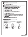
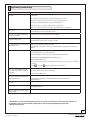
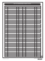
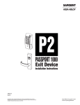
1
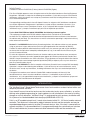
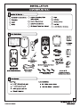
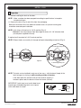
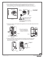
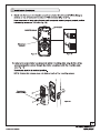
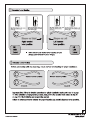
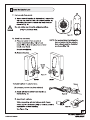
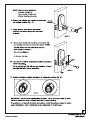
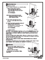
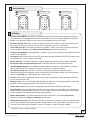
Industry Canada: Canadian ID: 6982A-YRHCPZW0 (Z-Wave); 6982A-YRHCPZB0 (Zigbee) This Class B digital apparatus meets all requirements of the Canadian Interference Causing Equipment Regulations. Operation is subject to the following two conditions: (1) this device may not cause harmful interference, and (2) this device must accept any interference received, including interference that may cause undesired operation. Cet appareillage numérique de la classe B répond à toutes les exigences de l’interférence canadienne causant des règlements d’équipement. L’opération est sujette aux deux conditions suivantes: (1) ce dispositif peut ne pas causer l’interférence nocive, et (2) ce dispositif doit accepter n’importe quelle interférence reçue, y compris l’interférence qui peut causer l’opération peu désirée. For the U4A-YRHCPZB0 and 6982A-YRHCPZB0, the following statement applies: “This equipment complies with FCC/IC radiation exposure limits set forth for an uncontrolled environment. This equipment should be installed and operated with minimum distance 20cm between the radiator and your body. This transmitter must not be co-located or operating in conjunction with any other antenna or transmitter.” Section 7.1.2 of RSS-GEN Under Industry Canada regulations, this radio transmitter may only operate using an antenna of a type and maximum (or lesser) gain approved for the transmitter by Industry Canada. To reduce potential radio interference to other users, the antenna type and its gain should be so chosen that the equivalent isotropically radiated power (e.i.r.p.) is not more than that necessary for successful communication. En vertu des règlements d'Industrie Canada, cet émetteur radio ne peut fonctionner avec une antenne d'un type et un maximum (ou moins) approuvés pour gagner de l'émetteur par Industrie Canada. Pour réduire le risque d'interférence aux autres utilisateurs, le type d'antenne et son gain doivent être choisies de façon que la puissance isotrope rayonnée équivalente (PIRE) ne dépasse pas ce qui est nécessaire pour une communication réussie. Section 7.1.3 of RSS-GEN This Device complies with Industry Canada License-exempt RSS standard(s). Operation is subject to the following two conditions: 1) this device may not cause interference, and 2) this device must accept any interference, including interference that may cause undesired operation of the device. Cet appareil est conforme avec Industrie Canada RSS standard exemptes de licence(s). Son fonctionnement est soumis aux deux conditions suivantes: 1) ce dispositif ne peut causer des interférences, et 2) cet appareil doit accepter toute interférence, y compris les interférences qui peuvent causer un mauvais fonctionnement du dispositif. INTRODUCTION The Yale Real Living™ Stand-alone Touchscreen Lever Lock combines a robust lockset with a contemporary electronic aesthetic. Users benefit from an interactive touchscreen that makes day-to-day access effortless, as well as offering voice-guided programming for simple updates to user information in the event of staffing changes or security breaches. Yale Real Living™ is engineered for quick and easy installation and fits in place of a standard deadbolt lock door prep (ANSI/BHMA A156.115). If this is an RF-enabled network lock, it needs to be located within 50 - 100 feet of another network controller. That distance is influenced by objects between the lock and the controller and may be expanded depending on proximity to other RF network devices. Also, if the lock is connected to a network controller, it is recommended that it is programmed through the centralized user interface (PC or hand-held device) to ensure communication between the lock and the controller unit. 3 P/N AYRT-220-INST-FUL Rev B An ASSA ABLOY Group brand INSTALL LOCK Preparation Before installing the lock on the door: NOTE: Make sure door has been prepped according to specifications in template included with lock. A. Remove the latch (Fig. A) and strike from the packaging. Both latch face and strike have adhesive-backed covers to prevent marring and should be removed upon installation. NOTE: Latch ships with backset in 2-3/8" position (Fig. A). Backset is the measurement from door edge to center of 2-1/8" diameter hole (see template supplied with lock). If required, pull to extend to 2-3/4" backset position. NOTE: Different holes are used for (2) through bolt posts depending on backset (Fig. A). 2-3/8" through bolt posts Figure A 2-3/4" through bolt posts NOTE: The latch can be installed in only one of two ways - with the bevel (slope) of the latch facing out or facing in while standing outside of the door. If the door opens in, the bevel will face the exterior (regular); if the doors opens out, the bevel will face the interior (reverse). IMPORTANT: Latch bevel must match door bevel and plunger of deadlocking latch must stop on strike when door is closed. Strike Plunger 5 P/N AYRT-220-INST-FUL Rev B An ASSA ABLOY Group brand 3. From outside of door, position the exterior escutcheon by first routing the wire harness through 2-1/8" diameter hole and under the latch (Fig. 4 & 5), then inserting the through posts* and tailpiece/square drive tube into the latch (Fig. 5). Exterior of Door Tailpiece horizontal Interior of Door "Top" of Drive Tube (marked BLACK) Figure 5 NOTE: Wire harness goes under latch (Fig. 4 & 5). Figure 4 *Posts are inserted in holes according to backset adjustment. (Refer to Fig. A under "Lock Preparation") 4. Remove the interior mounting plate (with gasket) from the back (door side) of the interior escutcheon (Fig. 6). A. Ensure that gasket on interior mounting plate is properly fitted (Fig. 7). Figure 6 Figure 7 Interior Escutcheon & Mounting Plate (with gasket) 5. Remove the battery cover from the back of the interior escutcheon (Fig. 8) by loosening the captive Phillips head screw, then lifting the cover up and out. Note tabs at bottom of cover. Phillips Head Screw Battery Cover Figure 8 7 P/N AYRT-220-INST-FUL Rev B An ASSA ABLOY Group brand Status Indicators 1 Low Battery Warning 2 Lockout Mode 3 Return to previous step Definitions All Code Lockout Mode: This feature is enabled by the Master PIN code. When enabled, it restricts all user PIN code access (except the Master PIN code). When the unit is in Lockout Mode, the red locked padlock (see above) will appear on the screen when attempting to enter a PIN code. Automatic Re-lock Time: After successful code entry and the unit unlocks, it will automatically re-lock after a default of thirty (30) seconds. Re-lock time is adjustable** from 10 - 240 seconds. Inside Indicator Light: Located on the interior escutcheon, it shows active status (Locked) of lock and can be enabled or disabled in the Advanced Lock Settings (Main Menu selection #3). Language Setting Mode: Choosing English (1), Spanish (2) or French (3) becomes the (default) setting for the lock's voice prompts. Low Battery: When battery power is low, the Low Battery Warning Indicator flashes RED. If battery power is completely lost, use the cylinder key override. Master PIN Code: The Master PIN code is used for programming and for feature settings and must be registered prior to programming the lock. The Master PIN code will also operate the lock. Network Module Setting: With the optional Network Module installed, this setting becomes available through the Main Menu (7) and allows the lock to connect with a network controller. One Touch Locking: When the latch is retracted, activating the keypad will extend the latch; (during Automatic Re-lock duration or when Automatic Re-lock is disabled). When One-Touch Re-lock is not in use (disabled), any valid PIN code will re-lock the lock. Previous: While in Menu Mode, pressing this icon (#3 above) cancels the current operation and returns the user to the previous step. Shutdown Time: The unit will shutdown (flashing RED) for a default** of sixty (60) seconds and not allow operation after the wrong code entry limit (5 attempts) has been met. Tamper Alert: Audible alarm sounds if attempting to forcibly remove outside lock from door. User PIN Code: The User code operates the lock. Maximum number of user codes is 250 with Network Module; without Network Module, maximum is 25 user codes. Note that when deleting User PIN code(s), screen will display User Number (not PIN code) being deleted. Volume Setting Mode: The volume setting for PIN code verification is set to Low (2) by default; otherwise it can be set to High (1) or Silent (3) for quiet areas. Wrong Code Entry Limit: After a specified number of unsuccessful attempts at entering a valid PIN code the unit will shut down and not allow operation. Wrong code entry limit is adjustable** from one (1) to ten (10) times. With no RF network enabled - default is 5 attempts; 10 with RF network enabled. **Adjustable only when using Network Module 15 P/N AYRT-220-INST-FUL Rev B An ASSA ABLOY Group brand To reset the lock to factory default, see the following: Reset Lock to Factory Default Reset Button The following procedure returns the lock to its factory defaults by deleting all user codes (including the Master PIN code*) and returning all programming features to their original factory default settings (see table below). 1. Remove the batteries and then remove the interior escutcheon to access the reset button. 2. The reset button (see image at right) is located above the PCB cable connector. 3. Hold down the reset button for a minimum of 3 seconds and then reinstall the batteries; once the batteries are properly installed, release the reset button. All features, including adjustable settings** (see below) should now be returned to factory default. *Upon reset (and initialization) of the lock, Master PIN Code Registration is the only option available and must be performed prior to any other programming of the lock. Interior Escutcheon Factory Default Settings Settings Factory Default Master PIN Code Registration required Automatic Re-lock Disabled Inside Indicator Light Disabled (Off) One Touch Locking Enabled Volume Setting Enabled (Low) Automatic Re-lock Time **30 Seconds Wrong Code Entry Limit **5 Times Shutdown Time **60 Seconds **Adjustable only when using Network Module See this section for programming instructions. 17 P/N AYRT-220-INST-FUL Rev B An ASSA ABLOY Group brand Feature Programming Through Menu Mode Using Master PIN code* 1. Touch the screen with the back of your hand or fingers to activate 2. Enter the 4-8 digit Master PIN code* followed by the . key. Lock Response: “Menu mode, enter number, press the key to continue.” 3. Enter digit corresponding to the function to be performed followed by the key. Follow the voice commands. *A unique Master PIN Code must be entered (registered) prior to any further programming of the lock. (See section on page 16 "Register Master PIN Code Before Programming") 1 2 M 3 Master PIN Code Setting User PIN Code Registration User Number (UN) 1~25: without network module M 1~250: with network module Register U Continue Complete Delete Continue Complete Default settings in bold. Advanced Lock Settings Automatic Re-lock Enable Disable Inside Indicator Light Enable Continue Disable One Touch Locking Enable Disable Volume Setting High Complete Low Silent Language Setting mode English Spanish French Lockout Mode Enable Disable **Network Module Setting **This function appears only with RF network module installed. Join the network Exit the network Note: If the lock is connected to a network controller, it is recommended that it is programmed through the centralized user interface (PC or hand-held device) to ensure communication between the lock and the controller unit. 19 P/N AYRT-220-INST-FUL Rev B An ASSA ABLOY Group brand Programming Troubleshooting Symptom Lock does not respond – door is open and accessible. Suggested Action The touchscreen will become active when pressed with the back of hand or fingers in at least 3 areas simultaneously. Use a larger area of the hand or fingers and verify contact with at least 3 areas. If touchscreen numbers are visible, check to see if they respond when pressed. Check batteries are installed and oriented correctly in the battery case. Check batteries are in good condition; replace batteries* if discharged. Check to see if touchscreen wire harness is fully connected and ensure it is not pinched. Lock does not respond – door is locked and inaccessible. Batteries may be completely discharged. The unit is on for a while, and then shows no reaction. Lights dim. The batteries do not have enough power. Replace the batteries*. Unit chimes to indicate code acceptance, but the door will not open. Check the door gaps for any foreign objects between door and frame. Unit operates to allow access, but will not automatically re-lock. Check to see if Automatic Re-lock Mode is enabled. PIN codes will not register. PIN codes must consist of 4 to 8 digits to register. Use mechanical key to gain entry and replace batteries*. Check that the wire harness is firmly connected to the PCB. Disable Automatic Re-lock Mode to lock the door (automatically)If low battery indicator is lit, replace batteries*. The same PIN code cannot be used for multiple users. Registration/management of PIN codes is set by the authority of Master PIN Code. The Master PIN code must be registered prior to adding any users. Contact the Master PIN Code user. User codes must be entered within 5 seconds (while the touchscreen is active) or the process will have to be restarted. The star (*) or pound (#) can not be used as part of the PIN code. Upon entering a PIN code and pressing the star (*) key, the unit displays an “invalid code” error or the lock times out without responding. Lockout Mode is enabled. Upon entering a PIN code and pressing the (*) key, the red padlock icon appears and there are different tones. Check to see if Lockout Mode** is enabled. The unit operates, but it makes no sound. Check to see if Silent Mode is enabled (see Programming Feature #4). The unit responds “Low Battery” This is the voice alarm alerting that it is time to replace the batteries. Replace all four (4) batteries with new AA Alkaline batteries*. Upon entering a PIN code and pressing the star (*) key, the unit responds “Wrong number of digits.” The digits entered were incorrect or incomplete. Re-enter the correct code. Only the Master PIN Code can enable Lockout Mode. Contact the Master PIN Code user. Setting/managing Lockout Mode is done through Master PIN Code only. Contact the Master PIN Code user. * When batteries are replaced, Network Module locks have a real time clock that will be set through the User Interface; it is recommended to verify correct date and time particularly those locks operating under Daylight Saving Time (DST). ** Network module units only 21 P/N AYRT-220-INST-FUL Rev B An ASSA ABLOY Group brand PIN CODE MANAGEMENT SAMPLE SHEET PIN Code Management (With Network Module - Up to 250 Users) - Duplicate Sheet to record entries User Type User Name User # PIN Code User Master User ___ User ___ User ___ User ___ User ___ User ___ User ___ User ___ User ___ User ___ User ___ User ___ User ___ User ___ User ___ User ___ User ___ User ___ User ___ User ___ User ___ User ___ User ___ User ___ User ___ User ___ User ___ User ___ User ___ User ___ User ___ User ___ User ___ User ___ User ___ User ___ User ___ User ___ User ___ User ___ User ___ User ___ User ___ User ___ User ___ User ___ User ___ User ___ User ___ User ___ User ___ User ___ User ___ User ___ User ___ User ___ User ___ User ___ User ___ User ___ User ___ User ___ User ___ User ___ User ___ User ___ User ___ User ___ User ___ User ___ User ___ User ___ User ___ User ___ User ___ User ___ User ___ User ___ User ___ User ___ User ___ User ___ User ___ User ___ User ___ User Name User # PIN Code 23 P/N AYRT-220-INST-FUL Rev B An ASSA ABLOY Group brand