1
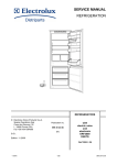
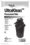
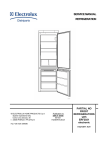
SERVICE MANUAL REFRIGERATION © ELECTROLUX HOME PRODUCTS S.p.A. Spares Operations Italy Corso Lino Zanussi, 30 I - 33080 PORCIA / PN (ITALY) Publication no. 599 36 17-69 031119 ITZ/SERVICE/AA Fax +39 0434 394096 PARTIAL NO FROST REFRIGERATOR with electronic timer PARTIAL NO FROST REFRIGERATORS With electronic timer 2/30 CONTENTS 1. INTRODUCTION ..................................................................................................................................................5 2. REFRIGERATOR CIRCUIT .................................................................................................................................9 3. ELECTRIC WIRING .......................................................................................................................................... 10 4. FUNCTIONAL DIAGRAM ................................................................................................................................. 12 5. OPERATION ..................................................................................................................................................... 13 a. Normal............................................................................................................................................................ 13 b. Normal with first switching on or power failure .............................................................................................. 14 c. Defrosting ....................................................................................................................................................... 15 d. Flow chart for the defrosting management .................................................................................................... 16 e. SUPER function ............................................................................................................................................. 17 f. Malfunctioning of temperature sensor............................................................................................................. 18 6. ACCESSIBILITY FREEZER COMPARTMENT................................................................................................ 19 a. Battery evaporator and fan ............................................................................................................................ 19 7. ACCESSIBILITY TO CONTROL PANEL ......................................................................................................... 20 a. Power and display board ............................................................................................................................... 24 8. TROUBLESHOOTING ...................................................................................................................................... 27 a. Excessive ice formation on the battery: ......................................................................................................... 27 b. Failed defrosting:............................................................................................................................................ 27 c. Manual defrosting procedure ......................................................................................................................... 28 d. ON and SUPER LEDs flashing ...................................................................................................................... 29 9. TECHNICAL FEATURES ................................................................................................................................. 30 PARTIAL NO FROST REFRIGERATOR with electronic timer 3/30 PARTIAL NO FROST REFRIGERATOR with electronic timer 4/30 1. INTRODUCTION This manual describes the PARTIAL NO FROST refrigerators with electronic timer produced in the Susegana factory called ZS. These models differ from the previous ones (see SM 599321723) since they do not feature the electromechanic timer because an electronic timer has been incorporated in the control and power board ERF1050-01.X (X indicates a variant of the board). It is a NO FROST (KBIN295 IT) appliance with the following PNCs: PNC 92577170000 92577170100 92577170101 92577170200 92577170201 92577170300 92577170301 92577170400 92577170600 92577170700 92577170701 92577170900 Date 20031212 20040116 20040716 20031205 20040716 20040305 20040716 20040305 20040305 20040227 20040910 20040409 Model JKG8498 SN81840-4I SN81840-4I 329.059 6/40199 329.059 6/40412 SN71840-4I SN71840-4I ERF2831 ZI921/8FF FI22/10NFA FI22/10NFA ZI921/8FF Brand Juno-Electrolux AEG AEG Privileg Privileg AEG AEG Electrolux Zanussi Rex-Electrolux Rex-Electrolux Zanussi The controls of the appliance are inserted inside the middle crossbar. PARTIAL NO FROST REFRIGERATOR with electronic timer 5/30 The appliance consists of the following compartments: freezer; cooler; The evaporating circuit consists of: battery evaporator (freezer compartment); tube evaporator (cooler compartment). Key: A = cooler compartment; B = freezer compartment. PARTIAL NO FROST REFRIGERATOR with electronic timer 6/30 Unlike the NO FROST refrigerators, in the PARTIAL NO FROST type the cooler and freezer compartments are separated physically. The battery evaporator cools only the freezer compartment, while the tube evaporator cools only the cooler compartment. The cold produced by the battery evaporator in the freezer compartment, is distributed by the fan placed behind the screen C. AIR FLOW In case of door opening the fan stops. To simulate the door closed, press the button of the freezer door. PARTIAL NO FROST REFRIGERATOR with electronic timer 7/30 The temperature measurement of the cooler compartment is performed by 1 sensor: cooler temperature sensor (placed on the cooler cell). The defrosting of the battery evaporator is controlled by the electronic board through the detection of the cooler and freezer door openings: cooler door button (placed on the left upper part of the control panel) freezer door button (placed on the right lower part of the control panel). Key: A = cooler door button; B = freezer door button; C = control panel; D = cooler temperature sensor. The sensor D features the foamed cable inside the cabinet, therefore it is not replaceable. PARTIAL NO FROST REFRIGERATOR with electronic timer 8/30 2. REFRIGERATOR CIRCUIT Key: 1. 2. 3. 4. 5. 6. 7. 8. compressor; condenser; anti-condensation coil; dehydrator filter; capillary; battery evaporator (freezer compartment); tube evaporator (cooler compartment); exchanger. PARTIAL NO FROST REFRIGERATOR with electronic timer 9/30 3. ELECTRIC WIRING (check the specific diagram for each model!) PARTIAL NO FROST REFRIGERATOR with electronic timer 10/30 Key: 3. 5. 9. 13. 15. 16. 24. 26. 27. 28. 41. compressor; motor protector; defrosting heater; lamp; cooler door switch; freezer door switch; fan; safety thermal switch (+40°C); defrosting cut-out switch (+10°C); running capacitor (only for the models which feature it); electronic board. a. yellow-green; b. brown; c. blue; d. white; e. black; f. grey; g. red; h. orange. PARTIAL NO FROST REFRIGERATOR with electronic timer 11/30 4. FUNCTIONAL DIAGRAM (check the specific diagram for each model!) Key: 3. 5. 9. 13. 15. 16. 24. 26. 27. 28. 41. compressor; motor protector; defrosting heater; lamp; cooler door switch; freezer door switch; fan; safety thermal switch (+40°C); defrosting cut-out switch (+10°C); running capacitor (only for the models which feature it); electronic board. a. yellow-green; b. brown; c. blue; d. white; e. black; f. grey; g. red; h. orange. PARTIAL NO FROST REFRIGERATOR with electronic timer 12/30 5. OPERATION a. Normal Warning: the electronic board is powered with a 220-240V 50Hz voltage even if the thermostat knob is on (OFF) position. Therefore, disconnect the appliance from the electric power before operating with the electronic board. When the thermostat knob is on (OFF) position it means that: the compressor is off; all Leds are off; the electronic board is powered (220-240V 50Hz ! ! !). Rotating the thermostat knob clockwise the green LED ON lights. In NOFROST freezers, the humidity inside the freezer compartment accumulates on the evaporator battery thanks to the air circulation, thus preventing the formation of frost on food. During normal operation time the electronic board powers the compressor (3) and the fan (24) circuits. The fan is activated or deactivated with a 2 minute delay compared to the compressor. The operation time which corresponds to the interval between the following defrosting lasts about 14 hours with normal opening of the door (it can last up to 71 hours if the door is never opened). The arrows in the picture indicate the current path. PARTIAL NO FROST REFRIGERATOR with electronic timer 13/30 b. Normal with first switching on or power failure In case of fault when the appliance is switched on for the first time or in case of a power failure, one of the two conditions described below occurs: 1. If the internal temperature is higher or the same as the thermostat cut-in temperature (CUT-IN), when the power is restored, the electronic board activates the compressor and the fan till the set temperature is reached and after 5 hours the electronic board activates the defrosting procedure (after the compressor cut-out). 2. If the internal temperature is lower than the thermostat cut-in temperature (CUT-IN), when the power is restored, the compressor functions in thermostatic conditions and after 5 hours the electronic board activates the defrosting procedure (after the compressor cut-out). The electronic board activates, in any case, the defrosting procedure 5 hours after the first switching on and after a power failure. Warning: if the thermostat knob is turned anti-clockwise till the zero position (OFF), all counters will be reset and once the thermostat knob has been rotated clockwise at ON position, the compressor will function in thermostatic conditions. PARTIAL NO FROST REFRIGERATOR with electronic timer 14/30 c. Defrosting All the humidity in the compartment accumulates on the evaporator, which is the coldest part of the compartment; periodically, about every 14 hours with normal door opening (up to 71 hours if the doors never open!), it is then necessary to defrost the ice on the battery. The defrosting starts after the compressor cut-out or if the compressor is on after 2,5 hours max. The electronic board disconnects the circuit which powers the compressor (3) and the fan (24) and, after controlling the presence of the defrosting heater, it powers the circuit of the defrosting heater (9) for a minimum time of about 20 minutes. If the defrosting heater is interrupted or its connector is detached, the ON and SUPER LEDs flash and the defrosting heater lasts 1 hour. Important: If the defrosting heater is interrupted or its connector is detached, the ON and SUPER LEDs flash and the defrosting phase lasts 1 hour. Please refer also to Service Bulletin 599376174 since the failure signaling could be wrong due to a “bug” in the software of the electronic board. The heat generated by the defrosting heater does not affect the freezer compartment temperature or the food packages temperature, because the thermal energy is consumed in the defrosting process of the evaporator ice. After 20 minutes, the board detects the defrosting signal every minute to identify the defrosting switch cut-out (27). At the defrosting switch cut-out, the electronic board switches the compressor on (3) with a 5 minute delay. After another 2 minute delay, when the air is already cold, the fan switches on too (24). If for any reason, the defrosting cut-out switch (27) does not switch on and the battery temperature rises up to 40 °C, the defrosting heater (9) will be switched off by the safety thermal switch (26). If 1 hour after the starting of the defrosting, the thermal switches did not cut out, the electronic board switches the defrosting heater off and continues its operation. The arrows in the picture indicate the current path. PARTIAL NO FROST REFRIGERATOR with electronic timer 15/30 d. Flow chart for the defrosting management POWER ON Defrosting after 5 hours (after the compressor cut-out or if the compressor is ON after 2,5 hours max.) YES Is cooler or freezer door open? see note # NO Defrosting after 14 hours (after the compressor cut-out or if compressor is ON after 2,5 hours max.) Defrosting after 30 hours (after the compressor cut-out or if the compressor is ON after 2,5 hours max.) YES YES Cooler or freezer door open? see note # NO Is the time less than 14 hours? NO Defrosting after 71 hours (after the compressor cut-out or if compressor is ON after 2,5 hours max.) Defrosting (after the compressor cut-out or if compressor is ON after 2,5 hours max.) PARTIAL NO FROST REFRIGERATOR with electronic timer 16/30 NOTE #: When the cooler or freezer door is open it means that one of the two doors is opened for more than 1 minute. At every defrosting the time is cancelled. e. SUPER function The SUPER function is activated by pushing the SUPER button therefore: The yellow LED corresponding to the SUPER function is on; The compressor functions in thermostatic conditions and not continuously (as the thermostat knob were in max. position) for a duration of about 52 hours, and then it deactivates automatically. If the button is pressed again, the SUPER function is deactivated: The corresponding yellow LED is switched off; The compressor functions in thermostatic conditions. The defrosting can occur with the SUPER function on. PARTIAL NO FROST REFRIGERATOR with electronic timer 17/30 f. Malfunctioning of temperature sensor If during the normal operation a failure of the NTC temperature sensor occurs (the signal coming from the sensor is out of range), then: The appliance functions with a pre-definite cycle where the compressor is powered for 30 minutes and remains off for 45 minutes alternatively; The defrosting procedure is activated every about 14 hours. When the sensor operates again normally the above two mentioned conditions are cancelled. NTC sensor characteristics: PARTIAL NO FROST REFRIGERATOR with electronic timer 18/30 6. ACCESSIBILITY FREEZER COMPARTMENT a. Battery evaporator and fan To access the battery evaporator and the fan perform the following operations: a) Remove the freezer drawers; b) Remove the fixing screws of the evaporator shield; remove the isolating panel; c) components: A) B) C) D) E) F) Battery evaporator; Fan; Thermal switches connectors +10 / +40 °C; Defrosting heater connector; Fan connector. Defrosting heater. In case of replacement of the fan it is necessary to ensure that the fan does NOT function with the suction. Note: The thermal switches (+10 / +40°C) are connected together therefore they are not available as single spare parts. PARTIAL NO FROST REFRIGERATOR with electronic timer 19/30 7. ACCESSIBILITY TO CONTROL PANEL To access the control panel and its components (power/display board, cooler/freezer switches and electric connectors) perform the following operations: a) components: A) B) C) D) E) F) Battery evaporator; Fan; Thermal switches connectors +10 / +40 °C; Defrosting heater connector; Fan connector. Defrosting heater. c) Remove the hinge cover of the opposite side of where the hinge is placed by using a cutting screwdriver as indicated in picture; b) Remove the hinge cover of the opposite side of where the hinge is placed by using a cutting screwdriver as indicated in picture; d) Remove the hinge cover of the opposite side of where the hinge is placed by using a cutting screwdriver as indicated in picture; PARTIAL NO FROST REFRIGERATOR with electronic timer 20/30 e) Remove the hinge cover of the opposite side of where the hinge is placed by using a cutting screwdriver as indicated in picture; f) Remove the hinge cover of the opposite side of where the hinge is placed by using a cutting screwdriver as indicated in picture; g) Remove the fixing screws of the control panel; h) Remove the control panel from the intermediate crossbar; PARTIAL NO FROST REFRIGERATOR with electronic timer 21/30 a) While remounting the control panel be careful with the wiring because it could interfere with the board connectors; b) Remove the wiring as indicated in picture; c) Put the control panel close to the intermediate crossbar and keep the wiring aside; d) Put the control panel close to the intermediate crossbar and keep the wiring aside; IMPORTANT: to avoid the liquid infiltrations there are some adhesive gaskets ( A and B ) and a polyester boss inside the control panel. In case of replacement of the components of the control panel it is obligatory to put the gaskets and the boss at the same place. The adhesive gasket A must be applied only on the cooler door button. PARTIAL NO FROST REFRIGERATOR with electronic timer 22/30 g) components: A) B) C) D) E) F) G) Electronic board; Connector J1 electronic board supply and compressor control; Connector J2 components supply (fan, defrosting heater and lamp); Connector J3/J6 temperature sensor; Connector J7 cooler and freezer door switch; SUPER button; Electronic thermostat knob. IMPORTANT: the electronic board features a protection that ensure that the compressor does not switch on before than 5 minutes from the last switching off ! PARTIAL NO FROST REFRIGERATOR with electronic timer 23/30 a. Power and display board - View of the electronic board (welding side): Optional components: - A reed element 1. 2. 3. 4. compressor free line neutral 1. 2. 3. 4. 5. lamp neutral neutral defrosting heater fan 1. NTC 2. NTC PARTIAL NO FROST REFRIGERATOR with electronic timer 24/30 1. NTC 2. free 3. NTC 1. 2. 3. 4. freezer door switch freezer door switch freezer door switch freezer door switch To identify the functions of the electronic boards, please refer to the following table (for the part nos. see the spare part lists of the specific model): Electronic board Thermal Buzzer ERF1050-01.F B NO Thermal type B Pos. min Cut-in Cut-out [°C] [°C] +11.5 +8 Green LED YES Pos. int Cut-in Cut-out [°C] [°C] +8 +5 Yellow LED YES Red LED NO Reed element NO SUPER button YES Pos. max Cut-in Cut-out [°C] [°C] +4.5 +3 PARTIAL NO FROST REFRIGERATOR with electronic timer 25/30 PARTIAL NO FROST REFRIGERATOR with electronic timer 26/30 8. TROUBLESHOOTING WARNING ! Switch off the power to the appliance before operating. a. Excessive ice formation on the battery: If the rubber valve remains open, the humid air outside the freezer compartment is ducted inside and it accumulates too much ice on the battery. The valve remains open if there are foreign bodies or if it looses elasticity; therefore, in the first case the foreign bodies must be removed, while in the latter the rubber valve must be replaced. b. Failed defrosting: In case of failed defrosting, the possible causes are: Sequence n° 1 POSSIBLE CAUSES The defrosting heater is interrupted 2 One or both switches of the thermal protectors are open HOW TO CONTROL SOLUTION Detach the power plug of the appliance, remove the connector of the heater and verify with the tester the correct resistance value to the connector clamps Frost the battery, then detach the power plug of the appliance, remove the connector of the thermal switches and verify with the tester the correct resistance value to the connector clamps If the resistance value does not correspond to the technical data, replace the heater PARTIAL NO FROST REFRIGERATOR with electronic timer If the resistance value does not correspond to 0 (zero Ohm) replace the thermal switches 27/30 c. Manual defrosting procedure To execute the testing and the service, a manual defrosting procedure has been introduced that has to be carried out with cold internal temperatures (this is to avoid the possible opening of the thermal protector of the defrosting heater). To start the manual procedure, ensure that: the electronic board is powered with thermostat knob ON, position 5 (or anyway in a position between 90° and 270°); the cooler door switch must be pressed (door closed). Perform the 3 following operations: 1. turn the thermostat knob to OFF position; 2. press the cooler door switch for 4 times (let pass at least 1 second between every opening/closure); 3. turn the thermostat knob to ON, position 5 (or anyway to a position between 90° and 270°); At this point the electronic board verifies the thermal cut-outs and all LEDs flash for 5 seconds; then if there aren’t any faults, the manual defrosting phase starts. If a fault occurs, the LEDs continue to flash. WARNING: after placing the thermostat knob in OFF position (operation 1), there are 15 seconds to perform the other 2 operations (operation 2-3) in the correct sequence. In case of error or incorrect execution of the operations, before executing once again the manual defrosting procedure, it is necessary to reset the standard functions switching off the power to the appliance (detach the power cable). The manual defrosting phase consists of: defrosting heater ON; green ON/OFF LED on; compressor and fan OFF; In this case the electronic board performs the defrosting phase as a standard function and then continues to operate normally. PARTIAL NO FROST REFRIGERATOR with electronic timer 28/30 Available time ON Thermostat knob OFF open Cooler door closed ON Defrosting phase OFF ON Green LED Yellow LED OFF Key: T = 15 seconds; t = 5 seconds (to check thermal protections); F = standard function. d. ON and SUPER LEDs flashing The ON and SUPER LEDs flash and the defrosting phase lasts 1 hour if the defrosting heater is interrupted or its connector is detached. Please refer also to Service Bulletin 599376174 since the failure signaling could be wrong due to a “bug” in the software of the electronic board. PARTIAL NO FROST REFRIGERATOR with electronic timer 29/30 9. TECHNICAL FEATURES 1) fan: Type Voltage [V – Hz] 220 - 50 F64-10.. Power [W] 3,1 Speed [rpm] 2000 2) Power and display board: Software version B100 Board version ERF1050-01.F 3) Defrosting heater: Voltage [V] 240 Resistance [Ohm] 510 Power [W] 113 4) Thermal switches: Type of thermal protector DEFROSTING SAFETY Cut-in temperature Opening Closing + 10 °C - 1 °C + 40 °C + 30 °C PARTIAL NO FROST REFRIGERATOR with electronic timer 30/30