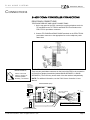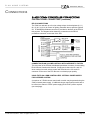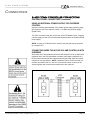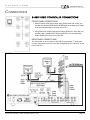
1
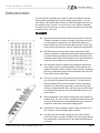
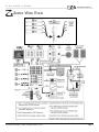
SYSTEM PRECISION PANEL - Series II
INSTALLATION
MANUAL
ELAN
HOME
SYSTEMS
INSTALLATION MANUAL
Series II
IMPORTANT SAFETY INFORMATION
Read Information—All the safety and operating information should be read before the appliance is operated.
Follow Information—All operating and use information should be followed.
Retain Information—The safety and operating information should be retained for future reference.
Heed Warnings—All warnings on the appliance and in the operating instructions should be heeded.
Wall Mounting—Mounting of this appliance should be done only by an authorized installer.
Ventilation—The appliances should be situated so that their location or position does not interfere with their proper ventilation. These appliances
should never be placed near or over a radiator or heat register. These appliances should not be placed in a built-in installation such as a bookcase or
cabinet that may impede the flow of air through the ventilation openings.
Non-Use Periods—Appliances that are left unattended and unused for long periods of time should be de-energized.
Power Sources—The appliances should be connected to a power supply only of the type described in the operating instructions or as marked
on each appliance. If you are not sure of the type of power supply to your home, consult your authorized ELAN dealer or local power company.
Grounding or Polarization—These audio products must be connected to a grounding-type alternating-current circuit on a dedicated circuit breaker. This is a safety feature. The green safety wire from the A.C. circuit must be connected.
Page i
© ELAN Home Systems 2002 • All rights reserved. 3/02
ELAN
HOME
SYSTEMS
INSTALLATION MANUAL
Series II
Water and Moisture—To reduce the risk of electric shock or fire, these appliances should not be used near water––for example, near a
bathtub, washbowl, kitchen sink, laundry tub, in a wet basement, or near a swimming pool.
Power Cord Protection—A.C.Power supply circuits should be routed by a certified electrician only, in accordance with the NEC standards.
Telephones—Avoid using a telephone (other than a cordless type) during an electrical storm. There may be a remote risk of electrical shock from
lightning. Do not use a telephone to report a gas leak if the leak is in the vicinity of the ELAN electronic equipment because of risk of fire or explosion.
Cleaning—Turn off the circuit breaker to this audio product before cleaning. Do not use liquid or aerosol cleaners. Use a damp cloth for cleaning.
Power Lines—An outdoor antenna should be located away from power lines. When installing an outside antenna system, extreme care should
be taken to avoid touching power lines or circuits, as contact with them may be fatal.
Outdoor Antenna Grounding—If an outside antenna or cable system is connected to these audio products, be sure the antenna or cable
system is grounded so as to provide some protection against voltage surges and built-up static charges. Section 810 of the U.S. National Electrical Code,
and Section 54 of the Canadian Electrical Code, provide information with respect to proper grounding of the mast and supporting structure, grounding of
the lead-in wire to an antenna discharge unit, size of grounding conductors, location of antenna-discharge unit, connection to grounding electrodes, and
requirements for the grounding electrode. See the grounding diagram (right).
Overloading—Do not overload wall outlets and extension cords, as this could result in
fire or electric shock.
Object and Liquid Entry—Never insert objects of any kind through the openings
of these appliances, as they may touch dangerous voltage points or short-out parts that could
result in a fire or electric shock. Care should be taken so that objects do not fall and liquids are
not spilled into the appliance through openings in the enclosure.
Servicing—Do not attempt to service these appliances yourself, as opening or removing
covers may expose you to dangerous voltage or other hazards. Refer all servicing to qualified
service personnel.
Damage Requiring Service—These appliances should be serviced by qualified
service personnel when:
• A power supply connection or a plug has been damaged or
• If liquid has been spilled into the appliance or objects have fallen into the appliance or
• The appliance has been exposed to water or moisture or
• The appliance does not appear to operate normally or exhibits a marked change in performance or
• The appliance has been dropped or the enclosure damaged.
Replacement Parts—When replacement parts are required, be sure the service technician has used replacement parts specified by the
manufacturer or that have the same characteristics as the original part. Unauthorized substitutions may result in fire, electric shock, or other hazards.
The Master Control Unit battery should be replaced only after turning the power off and only by an authorized installer.
Safety Check—Upon completion of any service or repairs to this audio product, ask the service technician to perform safety checks to determine
that the audio product is in proper operating condition.
Lightning—For added protection for these audio products during an electrical storm, or when they are left unattended and unused for long periods
of time, turn off the circuit breaker, and disconnect the antenna or cable system. This will prevent damage to the audio products due to lightning and
power-line surges.
© ELAN Home Systems 2002 • All rights reserved. 3/02
Page ii
ELAN
HOME
SYSTEMS
INSTALLATION MANUAL
Series II
TABLE
OF
CONTENTS
Introduction ..................................................................................1
Z• Series Wire Runs ....................................................................2
Rough-In/Trim Out ....................................................................3,4
Connections
Interconnect Cables ............................................................4
RJ-45 Pin Out.......................................................................5
Punchdown Connectors........................................................5
Silkscreen & Overlay.............................................................6
Z•PAD Connections..............................................................7
Z•025 Speaker Relay/AB Sensing Module Connections......7
Z•630 Preamp Controller Connections.................................8
Z•600 Comm Controller Connections...................................8
Linking Two PZ6s Together..............................................9,10
Telephone Service / Z•600 Connections.............................11
Door Speaker Assembly Connections................................11
Relay Connections.............................................................12
Volume Control Override Connections..........................12,13
Z•880 Connections.............................................................14
Z•Series Amplifier Connections..........................................15
Quick Reference Guide – Front Panel ......................................16
Quick Reference Guide – Rear Panel........................................17
Warranty ....................................................................................18
© ELAN Home Systems 2002 • All rights reserved. 3/02
Page iii
ELAN
HOME
SYSTEMS
INSTALLATION MANUAL
Series II
INTRODUCTION
The PZ6 Precision Wall Plate was created to make the installation of ELAN
Z•Series Multi-Source/Multi-Zone systems literally 'plug-and-play'. Like the
entire family of ELAN Essentials products, the PZ6 was designed with the custom installer in mind. Its goal––to cut hours off of every Z•Series installation
and assure that all system wire runs and Z• Series components are connected
properly first time, every time.
FEATURES
Front panel RJ45 jacks accommodate the connection of all ELAN
Z•Series components, including a multiple Z•630 systems of up to
12 zones (systems using three or four Z•630s will require two
PZ6’s). ELAN's new line of Essential Cables include 1 and 2 meter
RJ45-to-RJ45 interconnects to make all connections plug-and-play.
The PZ6 completely eliminates the need to interconnect ELAN
Z•Series components. Whereas numerous 'butt-splices' needed to
be made between the Z•630 PreAmp Controller, the Z•600 Comm
Controller and the Z•880 Video Controller so that they could 'talk' to
each other, the PC board on the PZ6 does all of that for you.
The rear panel features a standard 110 punchdown connector for
every Z•Series wire run, including Z•PADs, Z•025 modules, Door
Speaker Assemblies, Relays, Volume Control Overrides, Telephone
and even a punchdown connector that will interface with VIA! LCD
Touch Panel Precision Wall Plates.
The front of the panel is clearly silk-screened to make the connection of Z•Series components quick and easy. The rear panel PC
board is labeled with the name and function of each punchdown
connection. To make things even easier, a rear panel color-code
overlay is included with each PZ6. Just match up every Z•PAD and
Door Speaker Assembly wire to the corresponding connector and
punch it down!
Twelve gold-plated, 5-way speaker binding posts make speaker ter
mination easy. For clean, no-short connections, ELAN recommends
the use of its "BLACKJACK" gold-plated Banana plugs, which are \
accepted on both sides of the speaker binding posts.
Eight RCA-to-F barrel connectors make for easy connection of all
your coax wire runs to the Z•880 Video Controller.
+12VDC Inputs are provided on the front of the PZ6 for Z•025 &
VCO relay control. Just plug in ELAN's Z•027 power supply and the
PZ6 automatically routes the power to the appropriate punchdown
connectors.
© ELAN Home Systems 2002 • All rights reserved. 3/02
Page 1
ELAN
HOME
SYSTEMS
INSTALLATION MANUAL
Series II
SERIES WIRE RUNS
© ELAN Home Systems 2002 • All rights reserved. 3/02
Page 2
ELAN
HOME
SYSTEMS
INSTALLATION MANUAL
Series II
ROUGH-IN
(CUTOUT DIMENSIONS: 8.25"W
X
10.5"H)
INSTALLATION TIP
The cardboard insert
that the PZ6 sits in
inside the shipping
carton can be used
as a cutout template.
A new construction rough-in bracket (PBKT6P) is available for the PZ6. The
sliding frame on metal straps adjusts to any location between studs.
The PZ6 frame is equipped with four "winglets" which, when tightened, clamp
the frame securely against the rough-in bracket or, in retrofit applications,
against the drywall.
© ELAN Home Systems 2002 • All rights reserved. 3/02
Page 3
ELAN
HOME
SYSTEMS
INSTALLATION MANUAL
Series II
TRIM OUT
All system wire runs are pulled through the PZ6 frame. Lay the PZ6 front panel
on the floor in front of the frame and make all your connections. Dress the wires
in neat bundles––being careful not to pull off any punchdown connections––
and then carefully place the front panel back into the frame and secure using
the four screws. See pages 7-13 for detailed System Connections.
CONNECTIONS
INTERCONNECT CABLES
ELAN now carries a variety of interconnect cables for use with the PZ6 as well
as other Audio/Video applications
© ELAN Home Systems 2002 • All rights reserved. 3/02
Page 4
ELAN
HOME
SYSTEMS
INSTALLATION MANUAL
Series II
CONNECTIONS
-
CONT.
RJ-4
45 PIN OUT
Should you prefer to terminate your own RJ45 cables, refer to the diagram
below for the correct pin-out.
PZ6 PUNCHDOWN CONNECTORS
The back of the PZ6 uses standard 110 punchdown connectors for all
Z•System wire runs (with the exception of speakers and coax). Wires do not
need to be stripped prior to punchdown as the insulation will automatically be
displaced, and each punchdown row will accept two 24 or 22 AWG solid conductor wires. Use of a 110 punchdown tool is recommended.
NOTE: The PZ6 also comes with
Punchdown caps to ensure that
wiring connections won’t come
loose.
© ELAN Home Systems 2002 • All rights reserved. 3/02
Page 5
ELAN
HOME
SYSTEMS
INSTALLATION MANUAL
Series II
CONNECTIONS
-
CONT.
PZ6 CONNECTION SILK SCREEN & OVERLAY
The PZ6 has two ways for you to reference all your connections. Using
the silk screen on the PC board, and
then using the Color-Code Overlay
to double check all your punchdowns
(or vice-versa) will ensure that all
wires have been punched down to
the proper position.
The PC Board Silk Screen gives you the exact name-by-name connection for each wire
The COLOR-CODE Overlay gives a color-coded reference for Z•PAD and Door Speaker
Assembly connections
© ELAN Home Systems 2002 • All rights reserved. 3/02
Page 6
ELAN
HOME
SYSTEMS
INSTALLATION MANUAL
Series II
CONNECTIONS
-
CONT.
Z•PAD CONNECTIONS
These same connections are used
for Zones 7-12 on the second PZ6.
There are six keypad punchdown connectors provided on the rear panel of the
PZ6 - one for each of the six zones in a dual Z•630 System. The six keypad
punchdown connectors are labeled Zone 1 thru Zone 6.
CONNECTING MORE THAN ONE Z•PAD PER ZONE
INSTALLATION TIP
Use the Color-code
overlay to ensure
correct ZPAD
punchdown
connections
Two 22 or 24 AWG solid conductor wires can be punched down into each row
of the connector, making it easy to connect two Z•PADs per zone. If using more
than two Z•PADs in one zone, the keypad wires would need to be spliced to a
lead wire which would then be punched down to the connector.
NOTE: A maximum of six
ZPADS may be connected
to one Z630 PreAmp
Controller
Z•025 SPEAKER RELAY/AB SENSING MODULE
When using Z•025 Speaker Relay/AB Sensing Modules in conjunction with
Z•PADs, the Zone punchdown connectors on the PZ6 provide the necessary
connections for the VC+ and VC- wires that enable Page and Doorbell override
control. Use two of the remaining conductors from the CAT-5 keypad wire run
(Orange for VC+ and White/Brown for VC-) to make this connection.
© ELAN Home Systems 2002 • All rights reserved. 3/02
Page 7
ELAN
HOME
SYSTEMS
INSTALLATION MANUAL
Series II
CONNECTIONS
-
CONT.
Z•630 PREAMP CONTROLLER CONNECTIONS
PZ6 FRONT PANEL CONNECTIONS
SINGLE Z•630 (3 ZONE SYSTEM)
Using a RJ45-to-RJ45 interconnect cable (ELAN C4545 1M or 2M), connect the
jack labeled IR INPUTS on the back of the Z•630 to the jack labeled Z•630
Zones 1-3 on the front of the PZ6.
DUAL Z•630 (6 ZONE SYSTEM)
1. Using a RJ45-to-RJ45 interconnect cable (ELAN C4545 1M or 2M), connect the
jack labeled IR INPUTS on the back of Z•630 #1 (Zones 1-3) to the jack labeled
Z•630 Zones 1-3 on the front of the PZ6.
2. Using a RJ45-to-RJ45 interconnect cable (ELAN C4545 1M or 2M), connect the
jack labeled IR INPUTS on the back of Z•630 #2 (Zones 4-6) to the jack labeled
Z•630 Zones 4-6 on the front of the PZ6.
MULTIPLE Z•630 (9 OR 12 ZONE SYSTEM)
Using a RJ45-to-RJ45 interconnect cable (ELAN C4545 1M or 2M), connect the
jack labeled IR INPUTS on the back of Z•630 #3 (Zones 7-9 ), to the jack labeled
Z•630 Zones 1-3 on the front of the SECOND PZ6. Repeat for Zones 10-12
(Z•630 #4) and connect to the jack labeled Zones 4-6 on the SECOND PZ6.
Z•600 COMM CONTROLLER CONNECTIONS
PZ6 FRONT PANEL CONNECTIONS
There are six RJ45 connections for the Z•600 Comm Controller: TELCO, PHONE,
RELAY, CONTROL, DS1, and DS2.
PHONE SERVICE CONNECTIONS - Using RJ11-to-RJ11 interconnect cables, connect
the jack labeled TELCO IN on the Z•600 to the jack labeled TELCO on the PZ6; and the
jack labeled PHONE OUT on the Z•600 to the jack labeled PHONE on the PZ6.
RELAY - The RELAY interface must be made if any of the four telephone-activated contact closures that accessible via the Z•600 are to be utilized. Using a RJ45-to-RJ45
interconnect (ELAN C4545 1M or 2M), connect the jack labeled RELAY 1-4 OUTPUTS
on the Z•600 to the jack labeled RELAY on the front of the PZ6.
CONTROL - The CONTROL interface must be made when you are using ELAN Volume
Controls with Override. Using a RJ45-to-RJ45 interconnect cable (ELAN C4545 1M or
NOTE: If two PZ6’s will be used 2M), connect the jack labeled CONTROL OUTPUTS on the Z•600 to the jack labeled
CONTROL on the PZ6.
to accommodate a multiple
Z•630 system, all Z•600 connections are made to the first
PZ6 only. See diagram on following page.
DS1/DS2 - The Z•600 provides independent access to 2 ELAN Door Speaker
Assemblies. Using RJ45-to RJ45 interconnect cables (ELAN C4545 1M or 2M), connect
the jack(s) labeled DOOR SPEAKER 1 and DOOR SPEAKER 2 on the back of the
Z•600 to the corresponding jack(s) labeled DS1 and DS2 on the PZ6.
© ELAN Home Systems 2002 • All rights reserved. 3/02
Page 8
ELAN
HOME
SYSTEMS
INSTALLATION MANUAL
Series II
CONNECTIONS
Z•600 COMM CONTROLLER CONNECTIONS
REAR PANEL CONNECTIONS
TELEPHONE SERVICE AND HOUSE CONNECTIONS
1. On the rear panel of the PZ6, connect the incoming telephone service’s
TIP and RING to the TIP TELCO and RING TELCO terminals on the
PZ6’s TELCO punchdown connector.
2. Connect TIP PHONE and RING PHONE terminals on the PZ6’s TELCO
punchdown connector to the appropriate line on the telephone punchdown block.
INSTALLATION TIP
Use the color-code
overlay to ensure correct Door Speaker
Assembly connections.
DOOR SPEAKER ASSEMBLY CONNECTIONS
There are two punchdown connectors on the back of the PZ6 for the connection
of ELAN Door Speaker Assemblies (labeled DOOR SPEAKER 1 & DOOR
SPEAKER 2). The Z•600 may access each of the door stations independently.
NOTE: For additional information, see the Z•600 Comm Controller’s Users
Manual.
ELAN DSC2000 (rear)
BRAND X
ELECTRONIC
DOOR LATCH
MECHANISM
22/24 AWG 4-TWISTED
PAIR W/ SHEILD
DOORLATCH
POWER
SUPPLY
(Cut drain wire flush)
PZ6 Door
PZ6RM
Speaker Connector
Blue M+
Wh/Blue MWh/Green DB+
Wh/Orange L+
Green LOrange *DBBrown DS+
Wh/Brown DS-
*NOTE: Punchdown the stranded DRAIN wire first, then
punchdown the Orange DB- wire on top of it
DOORBELL
DOORBELL
BUTTON
BUTTON
(INCLUDED
WITH DSC2000)
(INCLUDED)
© ELAN Home Systems 2002 • All rights reserved. 3/02
Page 9
ELAN
HOME
SYSTEMS
INSTALLATION MANUAL
Series II
CONNECTIONS
Z•600 COMM CONTROLLER CONNECTIONS
PZ6 REAR PANEL CONNECTIONS (continued)
RELAY CONNECTIONS
The Z•600 can activate up to four low voltage relays via the telephone (#,1,1)
(#,1,2) (#,1,3) (#,1,4) for control of lighting, automatic doors, sprinkler systems,
etc. A dedicated punchdown connector is provided on the back of the PZ6 for
this purpose. The diagram below shows the connections to the RELAY
punchdown connector on the reart of the PZ6.
CONNECTING ELAN VOLUME CONTROLS WITH OVERRIDE TO THE PZ6
The rear panel of the PZ6 has a dedicated punchdown connector for terminating
ELAN Volume Controls with Override. Simply punch down the VC+ and VCwires coming from each volume control with override to the VC+ and VCconnector on the rear of the PZ6. Be sure to maintain proper polarity.
USING THE Z•600 COMM CONTROLLER'S INTERNAL POWER SUPPLY
FOR OVERRIDE CONTROL
A maximum of 5 ELAN volume controls with override may be powered using the
Z•600's internal power supply. If additional volume controls with override are to
be utilized, an external +12VDC power supply (ELAN Z•027) will be required
(see next page).
© ELAN Home Systems 2002 • All rights reserved. 3/02
Page 10
ELAN
HOME
SYSTEMS
INSTALLATION MANUAL
Series II
CONNECTIONS
Z•600 COMM CONTROLLER CONNECTIONS
PZ6 REAR PANEL CONNECTIONS (continued)
USING AN EXTERNAL POWER SUPPLY FOR OVERRIDE
CONTROL
Systems exceeding the limitations of the Z•600’s power supply (previous page)
will require the use of an external +12VDC, 1.5A MAX plug-in power supply
(ELAN Z•027).
The Z•027 connects to the jack on the front of the PZ6 labeled "VCO". Plugging
a power supply into the VCO jack automatically disconnects the Z•600's internal
power supply.
NOTE: As many as 32 ELAN Volume Controls with Override may be powered
by a single Z•027.
CONNECTING MORE THAN FOUR VOLUME CONTROLS WITH
OVERRIDE
Since each row of a punchdown connectors will accept two 22 or 24 AWG solid
conductor wires, the VCO punchdown connector can handle a maximum of 8
ELAN volume controls with the override feature by punching down two volume
controls per row (see below). NOTE: If additional volume control override connections are needed, the VC+ and VC- from several volume controls can be
spliced together and a lead wire punched down to the connector.
© ELAN Home Systems 2002 • All rights reserved. 3/02
Page 11
ELAN
HOME
SYSTEMS
INSTALLATION MANUAL
Series II
CONNECTIONS
Z•880 VIDEO CONTROLLER CONNECTIONS
FRONT PANEL CONNECTIONS
1. Using a RJ45-to-RJ45 interconnect cable (ELAN C4545 1M or 2M), connect the jack labeled NETWORK/IR INTERFACE on the back of the Z•880
to the jack labeled Z•880 on the front of the PZ6.
2. Using RCA-to-RCA Video Interconnect cables (ELAN CZV 1M or 2M) connect the Z•880's COMPOSITE VIDEO OUTPUTS to the corresponding
VIDEO ZONE jacks on the front of the PZ6
REAR PANEL CONNECTIONS
The video jacks on the rear panel of the PZ6 accept standard "F" connectors.
Connect each zone's coax wire run to the corresponding zone video jack on the
back of the PZ6.
© ELAN Home Systems 2002 • All rights reserved. 3/02
Page 12
ELAN
HOME
SYSTEMS
INSTALLATION MANUAL
Series II
CONNECTIONS
Z•SERIES AMPLIFIER CONNECTIONS
Make sure that the amplifier is powered down before making any of the following connections.
FRONT PANEL CONNECTIONS
Connect the amplifier's speaker outputs to the speaker binding posts on the
front of the PZ6. To avoid the possibility of a loose wire strand creating a short,
we recommend the use of ELAN BLACKJACK Banana Plugs.
REAR PANEL CONNECTIONS
Connect the wire runs coming from the speakers in each room to the rear panel
binding posts on the PZ6. Make sure each speaker is connected to the appropriate amplifier channel for that room. Once again we recommend the use of
ELAN BLACKJACK Banana Plugs to reduce the possibility of loose wire strands
causing shorts.
ELAN “BJACK” Blackjack
Gold-Plated Banana Plugs
© ELAN Home Systems 2002 • All rights reserved. 3/02
Page 13
ELAN
HOME
SYSTEMS
INSTALLATION MANUAL
Series II
CONNECTIONS
-
CONT.
LINKING TWO PZ6 PRECISION PANELS TOGETHER TO ACCOMMODATE A SYSTEM WITH
THREE OR FOUR Z•630 CHASSIS
Z•600
Z•630 #1 (Zones 1-3)
Z•630 #2 (Zones 4-6)
CAT 5 (See Page 15)
When linking two PZ6s together
to support a multiple chassis
Z 630 system with a Z 600
Comm Controller, PZ6 #2’s
Z 600 RJ45 jack inputs are not
used.
© ELAN Home Systems 2002 • All rights reserved. 3/02
Z•630 #3 (Zones 7-9)
Z•630 #4 (Zones 10-12)
Page 14
ELAN
HOME
SYSTEMS
INSTALLATION MANUAL
Series II
CONNECTIONS
-
CONT.
LINKING TWO PZ6 PRECISION PANELS TOGETHER TO ACCOMMODATE A SYSTEM WITH
THREE OR FOUR Z•630 CHASSIS - cont.
The new Series II version of the PZ6
enables the RS485+, RS485-, PAGE
& DOORBELL CONTROL, as well as
the PZ6’s GROUNDs to be linked.
PZ6 #1
NOTE: The PZ6s must have production dates later than 2/19/02.
This configuration enables the the
connection of as many as four Z 630
chassis, and facilitates the neat and
clean termination of all Z System
wiring.
GROUND
If three or four Z630 chassis are to be
linked using two PZ6s, the diagram to
the right details the connections of
the RS485+, RS485-, Z600 PAGE &
DOORBELL, and GROUND connections between the two PZ6s.
NOTE: The RS485 data bus is
common, therefore any of the RS485
data bus connections (circled) may
be used to link the first PZ6 to the
second PZ6.
P & DB
PZ6 #2
GROUND
P & DB
© ELAN Home Systems 2002 • All rights reserved. 3/02
Page 15
ELAN
HOME
SYSTEMS
INSTALLATION MANUAL
Series II
QUICK REFERENCE GUIDE
FRONT PANEL CONNECTIONS
© ELAN Home Systems 2002 • All rights reserved. 3/02
Page 16
ELAN
HOME
SYSTEMS
INSTALLATION MANUAL
Series II
QUICK REFERENCE GUIDE
REAR PANEL CONNECTIONS
© ELAN Home Systems 2002 • All rights reserved. 3/02
Page 17
ELAN
HOME
SYSTEMS
INSTALLATION MANUAL
Series II
Limited Warranty
ELAN HOME SYSTEMS, L.L.C. (“ELAN”) warrants equipment manufactured by it to be free
from defects in materials and workmanship for two (2) years from the date of purchase, with the
exception of speakers and volume controls, which have a ten (10) year warranty. If within the
applicable warranty period above purchaser discovers such item was not as warranted above
and promptly notifies ELAN writing, ELAN shall repair or replace the items at the company’s
option.
This warranty shall not apply (a) to equipment not manufactured by ELAN, (b) to equipment
which shall have been installed by other than an authorized ELAN installer, (c) to installed
equipment which is not installed to ELAN’s specifications, (d) to equipment which shall have
been repaired or altered by others than ELAN, (e) to equipment which shall have been subjected to negligence, accident, or damage by circumstances beyond ELAN’s control, including, but
not limited to, lightning, flood, electrical surge, tornado, earthquake, or any other catastrophic
events beyond ELAN’s control, or to improper operation, maintenance or storage, or to other
than normal use of service. With respect to equipment sold by, but not manufactured by ELAN,
the warranty obligations of ELAN shall in all respects conform and be limited to the warranty
actually extended to ELAN by its supplier. The foregoing warranties do not cover reimbursement
for labor, transportation, removal, installation, or other expenses which may be incurred in connection with repair or replacement.
Except as may be expressly provided and authorized in writing by ELAN, ELAN shall not be subject to any other obligations or liabilities whatsoever with respect to equipment manufactured by
ELAN or services rendered by ELAN.
THE FOREGOING WARRANTIES ARE EXCLUSIVE AND IN LIEU OF ALL OTHER
EXPRESSED AND IMPLIED WARRANTIES EXCEPT WARRANTIES OF TITLE, INCLUDING
BUT NOT LIMITED TO IMPLIED WARRANTIES OF MERCHANTABILITY AND FITNESS FOR
A PARTICULAR PURPOSE.
© ELAN Home Systems 2002 • All rights reserved. 3/02
Page 18