1
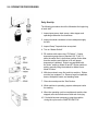
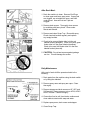
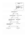
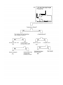
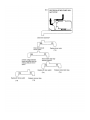
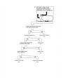
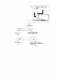
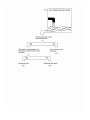
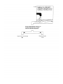
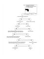
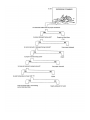
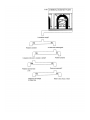
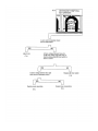
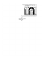
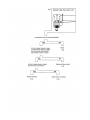
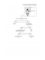
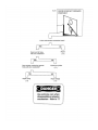
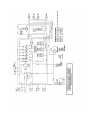
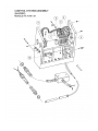
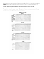
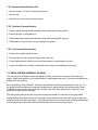
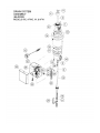
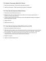
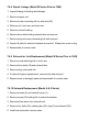
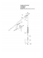
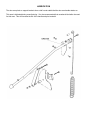
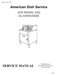
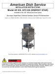
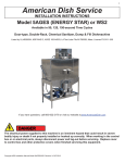
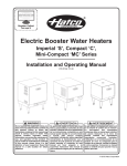
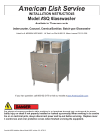
Effective Date: May, 2008
American Dish Service
ADS UPRIGHT DISHWASHERS
MODELS: AF/AFC-3D, AF/AFC-3DS, LW/LWC, 5AG, AF/AFC/AFB, AD25
SERVICE MANUAL
900 Blake Street
Edwardsville, Kansas 66111
(913)-422-3700
© 05/08
IMPORTANT:
American Dish Service provides this information as a service to our customers.
Keep all instructions for future reference. Although ADS will make every effort to
make sure the information in this service manual is correct and up-to-date, ADS
does not certify that this is the case, and should you decide to utilize this manual,
you do so at your own risk. ADS reserves the right to alter or update this
information at any time without notice. Should you desire to make sure that you
have the most up-to-date information, we would direct you to the appropriate
document on our website: www.AmericanDish.com. The instructions and
guidelines in this owners manual are given with the assumption that the
dishwasher has been installed, operated, and maintained properly and in
accordance with all applicable Codes, Ordinances, and Safety requirements.
Failure to install, operate, and maintain the machine in this manner will void the
ADS Warranty. ADS assumes no liability or control over the installation,
maintenance (service), or operation of the equipment. Product failure due to
improper installation, maintenance, and operation is not covered under the ADS
Warranty.
WARNING:
During the operation of all dishmachines, chemicals, high voltage electricity, and
normal operational functions can cause harm, bodily injury, or worse if proper
installation, operation, and maintenance are not observed. It is imperative that
the operator(s) are trained in the operation and made aware of the hazards that
can exist. This is the responsibility of the owner of this equipment. When
installing, operating, or maintaining your dishwasher you must follow all
applicable safety requirements, including the wearing of approved personal
protective equipment.
CONTENTS
1.0
GENERAL
2.0
OPERATOR PROCEDURES
3.0
INSTALLATION
4.0
CHEMICALS
5.0
PREVENTIVE MAINTENANCE
6.0
TROUBLESHOOTING
7.0
REPAIR PROCEDURES
8.0
REPLACEMENT PARTS
9.0
SERVICE BULLETIN
10.0
SPECIFICATION SHEETS
1.0 GENERAL
The ADS Dishmachine is a manually loaded chemical sanitizing dish washing machine intended for use
in restaurants or other food service facilities. The standard 20” x 20” rack is loaded with dishes, moved
into the machine and the doors are closed. The operator presses the cycle start button and the machine
operates. The cycle may range from 60 -150 seconds depending on the specific model. During
operation the operator may prepare the next rack of dirty dishes. When the cycle is complete the
operator moves the clean dishes out and the next rack of dirty dishes is placed in the machine.
The machine contains only enough water to fill the pump and spray system and cover the dishes. At the
beginning of each cycle, detergent is metered into the wash water and the dishes are sprayed at high
pressure. Rotating arms assure complete and even coverage. These arms are powered by the action of
the spray and therefore require no drive mechanism.
When washing is complete a solenoid raises the stopper at the bottom of the sump, and soiled wash
water drains by gravity from the machine. As water drains it washes the intake screen, thus removing
food particles and soil and carrying it into a separate scrap trap.
Near the end of drain, the fresh water solenoid valve opens and water flows through the pump and spray
system. This Pre-Rinse carries away soap, soil and wash water from the dishes, cabinet and spray
system. At the end of the Pre-Rinse cycle the drain closes and final rinse commences.
A chlorine based sanitizing chemical and a rinse-aid are metered into the rinse water which is sprayed
under high pressure on the dishes. The chemical sanitizing agent provides greater germ killing ability in
140° rinse water then conventional machines with 180° rinse. The rinse-aid causes water to flow from the
dishes in sheets rather than collect as drops. This exposes more surface to the air allowing it to dry faster
and at the same time prevents water spots from remaining on the dishes.
Rinse water remains in the sump to be recycles as wash water for the next rack. By purging the machine
of soil and detergent, recycling the rinse and using chemicals for sanitation, only a very small amount of
low temperature water is required which results in an economical and energy efficient machine.
2.0 OPERATOR PROCEDURES
Daily Start-Up
The following procedure should be followed at the beginning
of each shift:
1. Inspect spray arms, drain screen, drain stopper and
operating mechanism for cleanliness.
2. Inspect chemical containers to insure adequate supply
for shift.
3. Inspect Scrap Trap and clean as required.
4. Turn on “Master Switch”.
5. Fill machine with water using “Fill Switch”. If water
temperature gauge has not reached 120° F (49° C)
when the water level is just below overflow, drain water
from the machine and continue to fill until proper
temperature is attained. Drain is accomplished with
the “drain” switch on Model W and ET Series machines
and by manually lifting the drainball on Model A and
Model 5 Series.
6. With doors raised, move first rack into machine. Dishes
must be “pre-scrapped”, ie. Remove large food particles,
bones, toothpicks, seeds, and standing water.
7. Close doors and press the “Start” button.
8. While machine is operating, prepare subsequent racks
for washing.
9. When the operating cycle is complete and machine has
stopped, raise doors and remove dish rack for drying.
10. If it should become necessary to stop the machine
during the cycle use the “MASTER SWITCH”.
After Each Meal:
1. Drain the machine to clean. Remove End Plugs
to clean upper and lower spray arms. If spray jets
are clogged, use a toothpick to open, and rinse
under faucet. Arms will not turn if jets are
clogged.
2. Remove drain screen. Thoroughly clean screen
by scrubbing with heavy brush. Rinse under
faucet and reinstall.
3. Remove and clean Scrap Tray. Rinse with spray.
Check chemical buckets regularly and replace
any empty buckets.
4. Check to be sure red feeder tube is in the red
labeled bucket (detergent). Check to be sure green
feeder tube is in the green labeled (sanitizer).
Check to be sure blue feeder tube is in the blue
labeled bucket (rinse-aid).
5. CAUTION: Do not beat screen against garbage
can rim. This will damage the screen.
Daily Maintenance
At the end of each shift the operator should to the
following:
1. Drain water from the machine using the drain switch
or by lifting the drainball.
2. Remove spray arms and spray arm caps. Clean
thoroughly.
3. Remove stopper and drain screen on AF, AFC and
5AG models. Remove screen only on AFW, AFWC
and ET models. Clean thoroughly.
4. Clean other food or soil from interior surfaces and
clean cabinet exterior with soap and water.
5. Replace spray arms, drain screen and stopper.
6. Clean Scrap Trap.
3.0 INSTALLATION
See Installation Manual
3.1 START-UP
Perform the following start-up procedure. This should be done by a qualified service representative:
1. Check voltage rating on nameplate and confirm that electrical supply is correct.
2. Visually inspect machine for defects, shipping damage or improper installation.
3. Prime chemical pumps.
4. Take a cc vial and collect samples from each chemical tube outlet during a normal cycle and adjust
the chemical delivery accordingly.
5. Check spray arms and doors for proper operation.
6. Fill and operate machine. Insure that water level is correct and all components work properly.
7. Wash several loads of dishes including glasses and silverware. Insure that chemicals are metered
in the appropriate quantities and that dishes are clean.
8. Re-check for leakage of plumbing, pump or cabinet.
9. Confer with owner to insure that he understands the operation and is satisfied with the start-up.
3.2 REGISTRATION
Record Model #, Serial # and other necessary information on Warranty Card and forward to:
AMERICAN DISH SERVICE
900 Blake Street
Edwardsville, KS 66111
4.0 CHEMICALS
All ADS machines require detergent and sanitizer for proper operation. A rinse-aid may be used if
desired.
Selection of the proper chemicals and the correct amounts will depend on several factors. Proper
selection is vital if optimum results are to be realized. It may be necessary to change chemicals or adjust
the quantity after the initial selection. Initial settings on chemical cams are adjusted by the factory at
10cc of Detergent, 5cc of Sanitizer, and 5cc of Rinse-Aid.
Detergent
Detergent is used to “emulsify” grease and loosen soil. Emulsification is a process which suspends
grease in solution. The detergent also reduces surface tension of the water.
The detergent selected must be designed for low-energy warewashing. Always use established brands.
The proper quantity of detergent may vary over a wide range, and depends on the following factors
1.
2.
3.
4.
5.
Water hardness.
Type and amount of soil.
Length of time the dishware stands.
Iron content of water.
Detergent formulation.
For this reason, your chemical distributor should be consulted to determine the amount which will give
you the best results with lowest detergent usage. Your distributor should use a test kit to test water
hardness before making a recommendation. After the machine has been in use or if conditions change,
the setting can be readjusted for optimum results.
Sanitizer
Sanitizer should b 6% solution of sodium hypochlorite. The initial setting is 5cc and this should be
checked regularly with a Chlorine Test Kit. Free chlorine in the final rinse should be 50 ppm or more.
However, high concentrations can cause deterioration of metal.
Rinse-Aid
Rinse-aid reduces surface tension and causes the rinse water to run off in sheets rather than collect in
droplets. This exposes more water surface to the air which allows the glasses to dry faster and prevents
spot formation.
The optimum amount of rinse-aid varies depending on many of the same factors that affect detergent
usage. Consult your commercial chemical supplier.
Water Softeners
In many cases, a water softener should be added to correct for hard water conditions which impede the
operation of the unit. Contact ADS for complete details.
CAUTION: DO NOT WASH SILVER OR SILVERPLATE
WITH CHLORINE TYPE SANITIZER!
5.0 PREVENTIVE MAINTENANCE
Machine should be inspected approximately once a month. The following steps will help to eliminate
costly repair bills.
1. Check that all operator
procedures (2.2) have
been followed.
2. Inspect spray arm thumb
screws to insure they are
finger-tight.
3. Inspect drainball for
wear.
4. Manually spin spray
arms to insure that
bearings and pivots are
operational.
5. Operate doors and
inspect smooth
operation.
6. Slide a tray of dishes into
and through machine
to insure proper
alignment of tray track
and dishtable.
7. Using manual switch,
inspect fill rate by
draining and refilling. If
rate is slow, the line
strainer screen and/or
solenoid valve may
need servicing.
8. Remove control system
cover and:
a. Inspect cycle
counter.
b. Inspect peristaltic
pumps and rotors. If
necessary lubricate.
c. Inspect chemical
intake and discharge
tubes.
d. Inspect squeeze
tubes.
e. Inspect timer for
wear or damage.
f. Inspect wiring for
loose or broken
connections.
9. Cycle machine and:
a. Listen for rhythm of
spray arms.
b. Listen at pump intake
for surge due to
cavitation.
c. Inspect chemical
pick up tubes.
d. Inspect vacuum
breaker valve for
leaks.
e. Inspect timer for
proper mechanical
operation.
f. Observe water level
to insure machine
has completely
drained prior to start
of pre-rinse.
10. Test chlorine
concentration using
test paper.
50 ppm minimum.
6.0 TROUBLESHOOTING
Scope – This section should be used to isolate problems if the machine malfunctions. The following
charts will diagnose most problems that may be encountered with the exception of those which are rather
obvious. When a diagnosis has been made and confirmed, refer for Section 7.0 for repair procedures.
7.0 REPAIR PROCEDURES
Repair procedures are organized around the major sub-assemblies of the machine. Most common
procedures are included. In addition to specific procedures, each major sub-assembly is discussed with
respect to its construction and operation. Before attempting any repair, maintenance personnel should be
thoroughly familiar with the construction and operation of the equipment and should be certain that the
diagnosis is correct.
7.1 CABINET ASSEMBLY (61-0300 & 61-0400)
The cabinet is constructed of stainless steel, 10 gauge. Doors slide in a vertical track and are lined with a
bearing material.
7.1.1 Door Guide Adjustment
1. Remove door (1) from machine and thoroughly clean all sliding surfaces using steel wool if necessary.
2. Check door guide strip (2) for wear or damage and replace if necessary.
3. Replace door, align it vertically; also, align the right hand door guide.
4. Tighten screws on right hand guide.
5. Align left hand guide 1/16” to 1/8” from door and tighten screws.
6. With actuator arm still unattached, lift door and allow it to fall. If door does not free fall to its lowest
position, realign guides.
7. Reattach actuator link.
8. Check spring adjustment.
7.1.2 Tray Track Adjustment
1. Prior to adjustment of tray track (3), insure that the machine is level and in line with the adjoining
tables in accordance with 3.0.
2. Slightly loosen four bolts (4) which attach the tray track and move the track up or down as required
to bring it flush with tables.
3. Retighten bolts.
7.1.3 Height Adjustment
1. Place level on top of machine in both front-back and side–side directions to determine if machine is
out of level and in which direction.
2. Adjust level by turning lower portion of bullet feet (5) with an open-end or crescent wrench.
7.2 SPRAY SYSTEM (62-XXXX)
The spray system consists of upper and lower spray arms which rotate on bearings mounted to the
cabinet by a spray base. Plumbing from the pump and between the upper and lower spray bases is also
included. Vee-type jets on the spray arms concentrate the water into a flat, hard hitting pattern. “Pusher
jets” propel the arms. Speed of rotation is important, if the speed is too high, the spray does not
penetrate deep cavities; too slow and the force of the jets will overturn and damage glasses.
7.2.1 Pressure Check
1. Install special pressure fitting on one end of lower spray arm (1) and attach pressure gauge which
reads 0 – 20 PSI. (Pressure gauge and fitting available from ADS – Part #88-1048.)
2. Close doors and start machine.
3. Record pressure during wash portion of cycle. If pressure fluctuates, record maximum and minimum
pressure.
4. Normal pressure may range from 12 PSI (8437 KG/M2) to 17 PSI (11.953 KG/M2). If pressure is less
than 12 PSI (8437 KG/M2) or fluctuates more than 3 PSI (2109 KG/M2), refer to Section 6.11.
7.2.2 Bearing and/or Spray Arm Replacement
1. Remove upper spray arm (5) and bearing (4) by loosening three thumb screws (6).
2. Inspect bearing for scoring or excessive wear and replace if necessary.
3. Inspect spray arm housing for wear or scoring and jets for wear.
4. Replace spray arm as required.
7.3 RECIRCULATING PUMP (63-XXXX)
The recirculating pump is a close-coupled centrifugal pump of conventional design.
The motor is 1.5 HP operating at 3450 RPM (2875 RPM on 50 HZ models). The impeller (1) is mounted
directly on the motor shaft with a right hand thread.
Water is taken in at the drain casting and is pumped to the spray arms at approximately 41 GPM. Normal
pressure at the end of the spray arm is 14 – 17 PSI (9882 KG/M2 – 11953 KG/M2).
7.3.1 Gasket Replacement
1. Drain water from machine and open drain cock (2) on pump housing (3).
2. Place Master Switch in “off” position and remove fuses or open circuit breaker which services
machine. Tag fuse or breaker with “DO NOT TURN ON” sign to prevent accidental energization.
3. Remove pump housing bolts (4) and motor mount bolts.
4. Separate front and rear sections of pump housing. If it is necessary to use a screwdriver or wedge,
pry only at bolt hold locations (4) and do not mar the mating surfaces.
5. Clean impeller using bent ice pick in accordance with 7.3.2.
6. Scrape all old gasket material and sealant from both surfaces of pump housing. Clean thoroughly with
steel wool or extra fine emery cloth. Do not mar mating surfaces.
7. Reassemble pump and front housing using a new gasket. Threads on housing bolts should be
coated with pipe sealant.
8. Install motor mount bolts and test for operation and leakage.
7.3.2 Clean Impeller
1. Drain water from machine and open drain cock (2) on pump housing (3).
2. Place Master Switch in “off” position and remove fuses or open circuit breaker which services
machine. Tag fuse or breaker with “DO NOT TURN ON” sign to prevent accidental energization.
3. Remove pump housing bolts (4) and motor mount bolts.
4. Separate front and rear sections of pump housing. If it is necessary to use a screwdriver or wedge,
pry only at bolt hole locations (4) and do not mar the mating surfaces.
5. Clean impeller using bent ice pick. It is necessary to use the pick on each opening since obstructions
within the impeller cavities may not be seen.
6. Scrape all old gasket material and sealant from both surfaces of pump housing. Clean thoroughly with
steel wool or extra fine emery cloth. Do not mar mating surfaces.
7. Reassemble pump with front housing using a new gasket (5). Threads on housing bolts should be
coated with pipe sealant.
8. Install motor mount bolts and test for operation and leakage.
7.3.3 Motor / Seal Replacement
1. Drain water from machine and open drain cock on pump housing (3).
2. Place Master Switch in “off” position and remove fuses or open circuit breaker which services
machine. Tag fuse or breaker with “DO NOT TURN ON” sign to prevent accidental energization.
3. Remove pump housing bolts (4) and motor mount bolts.
4. Separate front and rear sections of pump housing. If it is necessary to use a screwdriver or wedge,
pry only at bolt hole locations and do not mar the mating surfaces.
5. Remove cap from rear of motor and hold motor shaft to prevent the shaft from turning. Unscrew
the impeller by turning counter-clockwise. If necessary, break the impeller loose by lightly tapping
against the vanes with a hammer and punch.
6. Remove four bolts (6) which hold the rear housing to the motor and separate rear housing from motor.
7. Clean pump shaft thoroughly using steel wool or extra fine emery cloth. THIS IS IMPORTANT!
8. Remove old seal.
9. Install rear half of new seal (7) using special seal driver. Seal must be square and seated properly at
bottom of housing. Always install a new seal when the rear housing is removed.
10. If motor is to be replaced, remove conduit and disconnect wires at motor junction box.
11. Install rear pump housing (8) on motor and install four bolts (6).
12. Lubricate shaft with SOAP. Do not use silicone or grease.
13. Install front half of seal using thread protector. It is vital that the seal is not cut or scraped by threads
or anything else. Insure that all pieces hare installed in accordance with 7.2.
14. Reassemble pump and front housing always using a new gasket. Threads on housing bolts (4)
should be coated with pipe sealant.
15. Install motor mount bolts and test for operation and leakage.
Seal Replacement Tools Available From ADS
7.3.4 Capacitor Replacement
1. Remove screws (9) holding capacitor housing (10) to motor.
2. Disconnect wires from old capacitor.
3. Connect new capacitor and replace cover.
7.4 CONTROL SYSTEM ASSEMBLY (64-XXXX)
The control system assembly encompasses all of those electrical components which operate the various
functions of the machine. Also included are the Chemical Pump Sub-Assemblies.
For a thorough understanding of the control system it is necessary to study the electrical diagrams.
7.4.1 Timer & Switches
The timer (1) consists of a drive motor and six cams. These cams open and close six corresponding
switches (6) which in turn control most functions of the machine.
Switch #1 controls both the timer motor and pump motor. When the machine is off and the timer is in its
neutral position, no power is supplies to either the pump or timer motors. When the machine cycle starts,
Switch #1 is activated and power is supplied to the timer motor which drives the timer cams through their
cycle and also to the Motor Starting Relay (4). The starting relay contains a set of heavy duty contacts
which are capable of carrying the large starting current used by the pump motor.
Switch #2 supplies power to the detergent metering pump (Red). The cam which actuates this switch is
adjustable in order to control both the start of detergent input and the amount.
Switch #3 supplies power to the solenoid which actuates the drain ball.
Switch #4 controls the solenoid valve which supplies fresh water to the machine. Its cam is adjustable in
order to control the start of purge, as well as, the water level.
Switch #5 and #6 supply power to the sanitizer (Green) and rinse-aid (Blue) metering pumps respectively.
The cams which operate these switches are also adjustable.
The instant start relay (3) supplies power to the timer and motor for approximately one second after the
start button is depressed. This allows time for the #1 cam (5) to actuate.
7.4.2 Timer Motor (7) Replacement
1. Remove two mounting screws and nuts.
2. Pull motor to the left, away from the timer frame until stopped by the pinion.
3. Slide motor up and forward so that motor shaft slides out slot in frame.
4. One at a time, disconnect wires and reconnect to new motor.
5. Replace motor in frame making sure that gear and pinion are meshed and that the motor is flush
against the frame with the shaft bushing locked in place at the bottom of the slot.
7.4.3 Cam Adjustment
The timer cams (2) which control the solenoid valve and chemical pumps are adjustable. These cams are
split and have a left and right side. The right side of the cam sets the point at which the solenoid valve
opens or the chemical pump starts. The left side sets the point at which the solenoid valve closes or
chemical pump stops.
THE RIGHT SIDE OF THE CAM SHOULD ALWAYS REMAIN AT FACTORY SETTING.
Adjustment of the left side of each cam will determine the length of time that the solenoid valve is open or
the chemical pump operates and, thus, controls the amount of water or chemical introduced into the
machine.
Cams are adjusted using the special wrench which fits into notches on the side of the cam.
The chart below shows factory cam settings. The right side of the cam should always be at this factory
setting but the left side may be changed to suit field conditions.
7.4.4 Anti-Vapor-Lock Modification
This modification should be implemented when water temperature is in excess of 160° F (71° C) then
vapor lock is unlikely and surging of the pump and corresponding fluctuation in pressure is probably due
to air leaks in the pump intake or through the anti-foam valve (See Burpwire section at back of book).
7.4.5 Instant Start Relay (3) Replacement
1. Unplug old relay from its socket.
2. Insert new relay.
7.4.6 Motor Relay (4) Replacement
1. One at a time, remove wires from the old relay and reconnect to the new relay.
2. Remove two mounting screws and nuts and old relay.
3. Put new relay into position and replace mounting screws and nuts.
7.4.7 Master Switch (12) Replacement – Models With Top Mount Control Box
1. One at a time, remove wires from old switch and reconnect to corresponding terminals on new switch.
2. Remove retaining nut and switch.
3. Install new switch and retaining nuts.
7.4.8 Master Switch (12) Replacement – Models With Front Mount Control Box
1. Remove suction and discharge tubes from chemical pump in front of switch.
2. Loosen two mounting screws and remove pump from mounting brackets.
3. Disconnect wires from pump motor and set pump aside.
4. Remove locknut from Master Switch and pull switch out of the cabinet.
5. One at a time, remove wire(s) from old switch and reconnect to new switch.
6. Install new switch and replace locknut.
7. Replace detergent pump.
7.4.9 Indicator Light Replacement – Model W Series Only
1. Bend retaining tabs and pull light assembly from cabinet leaving wires attached.
2. ONE AT A TIME disconnect wires from old light and connect to corresponding terminal of new light.
3. Inset new light assembly and bend retaining tabs to lock in place.
7.4.10 Chemical Pump Replacement
1. Remove suction and discharge tubes.
2. Loosen two mounting bolts and remove pump from mounting bracket.
3. Pull pump away from timer case and disconnect two wires.
4. Install new pump by reversing above procedure.
7.4.11 Replace Chemical Pump Tube (Squeeze Tube)
1. Remove suction and discharge tubes.
2. Remove four screws holding cover (13).
3. Remove chemical pump tube.
4. If rotor is to be replaced, remove the old rotor by loosening allen head set screw, install new rotor.
Always install new Chemical Pump Tube when replacing rotor.
5. Remove tube clips and place on new tube.
6. Install the new tube by reversing the above procedure.
7.4.12 Lubrication Pad Replacement
1. With rotor in horizontal position, remove old pieces of lubrication pad.
2. Thoroughly clean the area where pad sits by scraping and using cleaning solvent.
3. Install new pad using a suitable contact cement.
4. After cement has thoroughly dried, lubricate pad using light oil such as “3 in 1”.
7.4.13 Priming the Chemical Pumps
1. Turn off Master Switch (12).
2. Disconnect yellow wire from #1 Timer Switch.
3. Turn on Master Switch.
4. Manually rotate cam until the chemical pump to be primed starts to operate.
5. When priming is complete, rotate cam to next pump or to off position.
6. Turn off Master Switch and reconnect yellow wire.
7.5 FRESH WATER PLUMBING (65-XXXX)
Fresh water is introduced through a fitting in the wash pump intake where it is pumped through the spray
arms for rinsing. Soapy water from the wash cycle is rinsed from the pump and spray system, as well as,
from the dishes.
The check valve (2) prevents air from being sucked into the pump during the wash and rinse portion of
the cycle.
A vacuum breaker valve (3) is located at the top of the machine and is required by all plumbing codes. Its
purpose is to eliminate contamination of city water lines in the event that city water experiences a backflow condition.
The solenoid valve (1) opens and closes at the appropriate time to pre-rinse and then fill the machine. It
is activated by timer switch #4, the “FILL” switch.
A gate valve is installed to shut off water for service. A strainer filters out scale or rust particles which
could jam the solenoid valve.
7.5.1 Clean / Replace Strainer Screen
1. Shut off water.
2. Remove strainer cap (4).
3. Remove screen and inspect.
4. Slightly open shut-off valve to flush loose scale or dirt from the strainer housing.
5. If screen is clogged, soak in lime remover. If screen is damaged, replace.
6. Reassemble in reverse order.
7.5.3 Service Solenoid Valve Diaphragm
1. Shut off water with manual valve. NOTE: Relieve pressure by pushing fill switch momentarily.
2. Remove screw (1) and lift off solenoid coil.
3. Unscrew valve bonnet (2) using spanner or channel-locks. Insure that valve body (3) is held firmly
to prevent damage to plumbing.
4. Remove bonnet (2), o-ring (4) and diaphragm (5).
5. Clean screen (6) and valve body.
6. Inspect bleeder holes (7) for plugging and diaphragm for damage.
7. Reassemble in reverse order using new parts from diaphragm kit.
8. Clean strainer screen.
7.5.4 Replace Solenoid Valve Coil
1. Remove screw (1) on top of solenoid coil housing.
2. Remove coil.
3. Install coil on valve body and replace screw.
7.5.5 Overhaul Vacuum Breaker
1. Remove cap by turning counter-clockwise with channel-locks or pipe wrench.
2. Remove plunger (1) and gasket (2).
3. Clean gasket seat, plunger seat and stem using steel wool and lime remover.
4. Reassemble in reverse order using new plunger and gasket.
7.5.6 Overhaul Anti-Foam Valve
1. Remove four screws and lift off cover.
2. Clean plunger, bore and seat thoroughly using steel wool.
3. If seat is pitted replace entire valve using thread sealant or sealing tape at all joints.
4. If seat is in satisfactory condition, reassemble valve using a new diaphragm and spring.
7.6 DRAIN SYSTEM ASSEMBLY (66-XXXX)
The Drain System for Model A series and Model W series machines are shown on the following two
pages. When the drain ball is in its lowest position, it seals against the seat (17) and prevents water from
flowing out of the machine.
When actuated by Timer Switch #3, the drain solenoid raises the ball and allows water to flow out. On
the Model A series machines the solenoid is located directly above the ball and connects with a chain.
On Model W series machines the solenoid is located away from rising steam and is connected to the
drain ball through a push rod linkage.
The drain casting also houses the sump screen and thermometer and connects to the pump intake.
During the wash and rinse portions of the operation cycle, water flows into the drain casing, through the
sump screen and into the pump intake. Food particles collect on the sump screen during the wash period
and are carried away when the drain ball lifts and water flows over the screen to drain.
7.6.1 Cleaning the Sump Screen
1. Remove and clean screen (21) in accordance with Daily Maintenance Procedure, Section 2.2.
2. Inspect for lime build-up, and clean with lime remover if required.
3. Reassemble.
7.6.2 Replace Drain Plug
1. Remove screw holding drain plug (6 or 34) assembly to chain (35).
2. If the ball only is to be replaced, pull old ball from end of tube. Press new ball over drain tube using
soap for lubrication.
3. Reinstall drain tube.
7.6.3 Drain Seat Replacement
1. Remove six bolts holding drain elbow (15) to sump.
2. Separate elbow from sump and remove old gaskets and seat.
3. Thoroughly clean and scrape sealing surfaces of sump and elbow.
4. Install new seat using new gaskets. Use gasket sealing compound or RTV Silicone Sealant on both
sides of both gaskets.
5. Replace six bolts.
7.6.4 Replace Thermometer (Model W Series)
1. Remove sensor from sump using an open end wrench to turn locknut and another wrench to hold
nipple.
2. Remove locknut from dial.
3. Remove old thermometer.
4. Install new thermometer by reversing the above procedure. Use thread sealant or sealing tape on
sensor locknut threads.
7.6.5 Replace Thermometer (Model A & 5 Series)
1. Remove old thermometer (11) from sump using open end wrench.
2. Install new thermometer. Seal threads with pipe sealant or sealing tape.
7.6.6 Drain Solenoid Adjustment (Model A Series)
1. Remove two screws and solenoid cover (1).
2. Manually lift the solenoid armature (29) to insure that it moves freely through its stroke. If
armature is not free, replace solenoid.
3. Loosen four bolts (32) and slide solenoid up or down until drain ball is resting on the seat and
there is slight slack in the chain.
4. Tighten bolts (32).
5. Install solenoid cover (1).
7.6.7 Drain Solenoid Adjustment (Model W Series Prior to 1982)
1. Remove screw between link and outer arm.
2. With drain ball firmly seated, move link towards solenoid box until spring pressure is encountered.
Move link slightly further until a set of holes in link line up with hole in outer arm. Insert screw.
3. Check adjustment. Drain ball should lift above seat at least 3/8” when solenoid is fully
retracted and should seat firmly and seal with solenoid extended.
4. Readjust as required.
5. Tighten four bolts and replace cover.
7.6.8 Repair Linkage (Model W Series Prior to 1982)
1. Inspect linkage for binding and damage.
2. Remove stopper rod.
3. Remove screw connecting link to outer arm (20).
4. Remove nut, inner arm, and outer arm.
5. Remove nut and bushing.
6. Remove three bolts holding solenoid box and remove.
7. Remove plug and screw connecting link with solenoid.
8. Inspect all parts for wear and replace as required. Always use a new o-ring.
9. Reassemble in reverse order.
7.6.9 Solenoid or Link Replacement (Model W Series Prior to 1982)
1. Remove screw attaching link to outer arm.
2. Remove three bolts (18) and solenoid box.
3. Remove plug, screw and link.
4. If solenoid requires replacement, remove bolts and solenoid.
5. Replace worn or damaged parts and reassemble in reverse order.
7.6.10 Solenoid Replacement (Model A & 5 Series)
1. Remove screws (2) and solenoid cover (1).
2. Remove screw (25) holding link to solenoid armature.
3. Disconnect two wires from solenoid coil.
4. Remove four bolts (32), retaining bar (36), stop (3) and solenoid (29).
5. Install new solenoid in reverse order.
7.6.11 Drain Ball Adjustment (Model W and ET Series 1982 and Newer)
1. Unscrew wingnut (4) and remove drain tube assembly (6) from drain rod (9).
2. Using a 7/16” wrench, turn ¼-20 nut clockwise to lower drain ball and counter-clockwise to
raise the drain ball.
3. Reassemble in reverse order. (NOTE: Never adjust drain ball height down at the ‘L’ bracket (20).
After adjustments, verify machine holds water while idle and completely drains tank during cycle.)
7.6.12 Drain Linkage Adjustment (Model W and ET Series 1982 and Newer)
1. Loosen ¼-20 nuts below the ‘L’ bracket (20).
2. Spin push rod (9) to verify it is straight (if bent, replace).
3. Adjust the slotted hole on the ‘L’ bracket (20) so that it travels up and down with the push rod (9).
4. Tighten ¼-20 nuts. Recheck ‘L’ bracket (20) and push rod (9) for free travel up and down.
5. Check drain ball adjustment. If adjustment is needed, see 7.6.11.
7.7 DOOR ACTUATOR ASSEMBLY (67-XXXX)
The door actuator on all models consists of a spring loaded arm linked to the doors. The mechanism is
designed to maintain the door in either the open or closed position and to assist operator effort as doors
are raised.
7.7.1 Spring Adjustment
1. Turn nut (12) to increase or decrease tension. Insure that both springs are adjusted evenly on pass
thru models.
2. Check adjustment by operating door. The door should remain raised when placed in the raised
position and remain lowered when placed in the closed position.
7.7.2 Linkage Repair
1. Remove bolt attaching door links (2) to doors.
2. Carefully raise door operating arm to vertical position to release spring tension.
3. Attach a 4” turnbuckle between the spring (3) and the eye-bolt (4) and tighten until spring hook (5)
is free.
4. Loosen turnbuckle until spring tension is relieved.
5. Repeat steps 3 and 4 for opposite spring.
6. Inspect all parts for wear, binding or damage and replace as required.
7. Reassemble in reverse order.
8. Adjust per 7.7.1.
9.0 SERVICE BULLETIN
Cautions on Inside Sump Drain Systems (ET-AF, AFW & AFWC)
A. Unscrew wing nut and remove drain tube assembly
from drain rod.
B. Using a 7/16” wrench, turn ¼-20 nut clockwise two
complete turns and reassemble. This procedure
regulates water flow to the drain, thus eliminating
back pressure. If two complete turns does not
eliminate the back pressure leak, repeat procedure
to obtain desired results. CAUTION: Make sure
when making adjustments that machine completely
removes all water from tank in the drain cycle mode.
1. Drain should be plumbed with 1 ½” pipe or larger.
Do not reduce pipe. If necessary to reduce pipe, do
it as far away from machine as possible.
2. Drain should be plumbed straight out 8” before
making any turns. If unable to plumb straight out,
then try to adapt to a larger pipe before making
any turns.
3. Do not connect to a slow running or a plugged drain.
4. If your installation dictates that you cannot follow
the recommended procedures (1 – 3), then the
above drain adjustment may be necessary.
5. Do not operate machine with the water level too high.
(Not above the brass wing nut on the drain tube.)
6. DO NOT PLUMB DRAIN UPHILL.
IMPORTANT:
CHECK FOR BENT OR BINDING ROD AND LINK.
ADJUST FOR SMOOTH TRAVEL UP & DOWN.
LUBRICATION
The door arm pivots or support brackets have a half round saddle that the door arm handle rotates on.
This area is lubricated during manufacturing. It is also recommended that occasional lubrication be used
for this area. This will increase the life of the handle and pivot material.
BURPWIRE
To wire an ADS batch-type machine for a burp cycle, the following procedures have been prepared:
On the top terminal of the sanitizer micro-switch (5th cam from the left) there are two wires joined together
by connector. These are the yellow and brown coded wires.
Remove these wires from the switch and separate the terminal connectors. Replace the yellow to the
original top terminal on the switch and move the brown wire down to the middle terminal.
Make sure that these wires and terminals do not touch one another.
Now, as you look at the wires on the sanitizer switch they should now be yellow on top, brown on the
middle, and green on the bottom terminal.
The motor will now stop during the sanitizer / rinse-aid and fill sequence and start again to finish the rinse.
This will allow air to escape the pump that has been trapped by excessive heat (above 150° F) or
pressure dynamics of the water.
WARNING: Diswasher pump will shut off for a few seconds during cycle. Inform operator to
not open the door until entire cycle is finished.
American Dish Service
Manufacturer of low and high temperature
Commercial Dishwashers and Glasswashers
900 Blake Street
Edwardsville, Kansas 66111
Ph:(913) 422-3700
Fax:(913) 422-6630