1
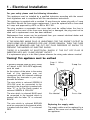
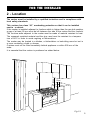
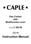
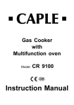
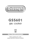
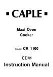
Gas Cooker
with
Gas Oven
Model:
CRG 902 SS
GB
Instruction Manual
Thank you for buying your new CAPLE cooker. To ensure that you get the best
results from your new CAPLE cooker, we strongly suggest that you read this instruction manual thoroughly before use. This manual contains installation advice, cleaning
tips and a cooking guide, as well as other important facts about your CAPLE cooker.
If treated with care, your CAPLE appliance should give you years of trouble-free
cooking.
For Spare Parts, Technical Advice
or Product Service call the
CAPLE HELPLINE on 0870 241 1142
(Answerphone outside office hours)
The
-
2
CE marking confirms that the appliance conforms to the following EU directives:
safety requirements of EEC Directive “Gas” 90/396;
safety requirements of EEC Directive “Low voltage” 73/23;
protection requirements of EEC Directive “EMC” 89/336;
requirements of EEC Directive 93/68.
Safety Reminders
Instruction Book
This appliance should only be used for
it’s intended purpose as described in
these instructions.
Ensure that you fully understand these
instructions before operating this appliance.
DO NOT line the oven, grids, trays etc.
with aluminium foil as this could adversely affect the heating elements and it
could also damage the interior surfaces.
DO NOT place flammable materials in
the oven or in the storage compartment.
Space Requirements
Ensure that the specified ventilation
space around the appliance is not
obstructed.
Food Splashes
Always wipe clean the oven after use.
Food splashes can carry on cooking next
time and may become a fire hazard.
Hot Surfaces
It is important to remember that the surfaces of cooking appliances get hot during use and retain the heat for some time
after switching off.
It is therefore advisable to keep small
children away from the appliance.
Faults
Do not continue to use this appliance if
it appears to be faulty.
After Use
After use, ensure that the hob knobs are
in position ● (off), and close the main
gas delivery valve or the gas cylinder
valve.
Switch the oven controls off.
Always switch off at the isolating switch
before cleaning the appliance, or
attempting any maintenance task, or
when not in use for long periods (when
on holiday).
CAPLE Service
The Grill burner
Is exposed, so take great care when
placing food in the oven or removing it.
Use the grill pan handles or gloves.
To ensure the continued safe and efficient operation of this appliance, we recommend that any servicing or repairs are
carried out only by an authorised CAPLE
SERVICE ENGINEER.
3
1 - Electrical Installation
For your safety please read the following information:
This appliance must be installed by a qualified technician according with the current
local regulations and in compliance with the manufacturer instructions.
This appliance is supplied with a moulded 13 amp three pin mains plug with a 3 amp
fuse fitted. Should the fuse require replacement, it must be replaced with a fuse rated
at 3 amp and approved by ASTA or BSI to BS 1362.
The plug contains a removable fuse cover that must be refitted when the fuse is
replaced. In the event of the fuse cover being lost or damaged, the plug must not be
used until a replacement cover has been obtained.
Replacement fuse covers can be purchased from your nearest electrical dealer and
must be the sarne colour as the original.
IF THE MOULDED MAINS PLUG IS UNSUITABLE FOR THE SOCKET OUTLET IN
YOUR HOME OR IS REMOVED FOR ANY OTHER REASON, THEN THE FUSE
SHOULD BE REMOVED AND THE CUT OFF PLUG DISPOSED OF SAFELY TO
PREVENT THE HAZARD OF ELECTRIC SHOCK.
THERE IS A DANGER OF ELECTRICAL SHOCK IF THE CUT OFF PLUG IS
INSERTED INTO ANY 13 AMP SOCKET OUTLET.
If a replacement plug is to be fitted, please observe the wiring code shown overleaf.
Warning! This appliance must be earthed
A properly earthed three pin plug (fused
at 3 amps, to BS 1362 ASTA approved)
must be used.
Green & Yellow
Earth
3 amp fuse
As the colours of the wires in the mains
lead of this appliance may not
correspond with the coloured markings
identifying the terminals in your plug,
proceed as follows.
The wire which is coloured GREEN &
YELLOW must be connected to the
terminal in the plug which is marked with
letter "E" or by the Earth symbol or
coloured GREEN & YELLOW.
The wire which is coloured BLUE must
be connected to the terminal which is
marked with the letter "N" or coloured
BLACK.
The wire which is coloured BROWN
must be connected to the terminal which
is marked with the letter "L" or coloured
RED.
4
Brown Live
Blue Neutral
Fig. 1.1
Replacing the supply cable
The supply cable must be replaced by a
cable of the same sort as that fitted to
the appliance.
FOR THE INSTALLER
2 - Location
The cooker must be installed by a qualified technician and in compliance with
local safety standards.
450 mm
800 mm
This cookers has class “2/1” overheating protection so that it can be installed
next to a cabinet.
If the cooker is installed adjacent to furniture which is higher than the gas hob cooktop,
a gap of at least 50 mm must be left between the side of the cooker and the furniture.
The furniture walls adjacent to the cooker must be made of material resistant to heat.
The veneered syntetical material and the glue used must be resistant to a temperature of 90°C in order to avoid ungluing or deformations.
The cooker may be located in a kitchen, a kitchen/diner or bed-sitting room but not in
a room containing a bath or shower.
Curtains must not be fitted immediatly behind appliance or within 500 mm of the
sides.
It is essential that the cooker is positioned as stated below.
50 mm
500 mm
Fig. 2.1
5
ASSEMBLING THE BACKGUARD
1. Insert the side supports S and D into the backguard B (see fig. 2.2)
2. Insert the backguard group into the support guides in the cooker
3. The backguard can be removed for cleaning or fixed with a screw through the hole
C.
D
Fig. 2.2
B
S
C
FITTING THE ADJUSTABLE FEET
The adjustable feet must be fitted to the base of the cooker before use.
Rest the rear of the cooker an a piece of the polystyrene packaging exposing the base
for the fitting of the feet.
Fit the 4 legs by screwing them tight into the support base as shown in picture 2.4.
Fig. 2.3
6
Fig. 2.4
WARNING
When raising cooker to upright position always ensure two people carry
out this manoeuvre to prevent damage to the adjustable feet (fig. 2.5).
WARNING
Be carefull: do not lift the cooker by
the door handle when raising to the
upright position (fig. 2.6).
WARNING
When moving cooker to its final position
DO NOT DRAG (fig. 2.7).
Lift feet clear of floor (fig. 2.5).
Fig. 2.5
LEVELLING THE COOKER
The cooker may be levelled by screwing
the lower ends of the feet IN or OUT
(fig. 2.8).
Fig. 2.6
Fig. 2.7
Fig. 2.8
7
Provison for ventilation
The room containing the cooker should have an air supply in accordance with BS.5540:
Part 2: 1989.
All rooms require an openable window or equivalent while some rooms require a permanent vent in addition to the openable window.
The cooker should not be installed in a bed-sitting room, of volume less than 21 m3.
Where a DOMESTIC COOKER is installed in a room or internal space, that room or
internal space shall be provided with a permanent opening which communicates directly
with outside air and is sized in accordance with table below. In domestic premises the
permanent opening shall be an air vent.
If there are other fuel burning appliances in the same room, BS.5540: Part 2: 1989
should be consulted to determine the requisite air vent requirements.
If the cooker is installed in a cellar or basement, it is advisable to provide an air vent
of effective area 100 cm2, irrespective of the room volume.
MINIMUM PERMANENT OPENING FREE AREA FOR FLUELESS APPLIANCE
Room volume
Type of appliance
Maximum
appliance
rated input
limit
< 5 m3
Domestic oven, hotplate, grill or any combination thereof.
None
100
cm2
5 m3 to 10 11 m3 to
> 20 m3
m3
20 m3
50 (❊)
cm2
Nil
cm2
Nil
cm2
Openable
window or
equivalent also
required
Yes
(❊) If the room or internal space containing these appliances has a door which opens
directly to outside, no permanent opening is required.
8
3 - Gas connection
GAS INSTALLATION
GAS CONNECTION
IMPORTANT NOTE
The installation of the cooker to Natural
Gas or LP Gas must be carried out by
a qualified gas engineer. Installers shall
take due account of the provisions of the
relevant British Standards Code of
Practice, the Gas Safety Regulations
and the Building Standards (Scotland)
(Consolidation) Regulations issued by
the Scottish Development Department.
This appliance is supplied for use on
NATURAL GAS only and cannot be used
on any other gas without modification.
This appliance is manufactured for
conversion to LPG if required and is
supplied with a conversion kit.
The cooker must be installed by a
qualified person in accordance with the
Gas Safety (Installation and Use)
(Amendment) Regulation 1990 and the
relevant building/l.E.E. Regulations.
The following British Standards should
be used as reference when installing this
appliance.
BS6172 1990, BS5440 part 2 1989 and
BS6891 1988.
Failure to install the appliance correctly
could invalidate any manufacturers
warranty and lead to prosecution under
the above quoted regulation.
In the UK C.O.R.G.I registered installers
are authorised to undertake the
installation and service work in
compliance with the above regulations.
INSTALLATION TO NATURAL GAS
Installation to Natural Gas must conform
to the Code of Practice, etc. The supply
pressure for Natural Gas is 20 mbar.
INSTALLATION TO LP GAS
This appliance must only be connected
to LPG after an LPG conversion kit has
been fitted, (see pages from 11 to 17).
When operating on Butane gas a supply
pressure of 28-30 mbar is required.
When using Propane gas a supply
pressure of 37 mbar is required.
The installation must conform to the
relevant British Standards.
Warning: Only a qualified gas engineer,
also with technical knowledge of
electricity should install the cooker. He
should observe the Regulations and
Codes of Practice governing such
installation of gas cookers.
Note: It is recommended that the gas
connection to the cooker is installed with
a flexible connecting tube made to BS
5386.
9
GAS CONNECTION
The gas supply must be connected to
the gas inlet which is located at the left
or the right hand rear of the appliance
(fig. 3.1).
The pipe does not cross the cooker.
When screwing the connecting tube
operate with two spanners (fig. 3.2).
The unused end inlet pipe must be
closed with the plug, interposing the
gasket.
After connecting to the mains, check
that the coupling are correctly sealed,
using soapy solution, but never a
flame.
Fig. 3.2
Plug
Fig. 3.1
10
Conversion to LPG
Injectors replacement of top burners
To replace the injectors it is necessary to lift the hobtop and proceed as follows:
– Remove pan-supports and burners from the hobtop.
– Remove the backguard “E”.
– Unscrew the two screws “B” and remove the sockets (Fig. 3.3).
– Unscrew the two screws “C” and remove the two side trims and joints pulling upwards.
– Pull forwards the hobtop to release it, then lift following arrow “D” (Fig. 3.3)
– Hold the hobtop open by a support.
– Fully raise the adjusting air tube A (fig. 3.4) in order to easily reach the injector.
– By an angle 7 spanner, remove injector “J” from its housing and replace it with the
correct one depending on the kind of gas (see following table - page 13).
Each injector can be identified by the engraving of the hole diameter expressed in
hundredths of a millimetre.
B
E
B
D
Fig. 3.3
C
C
Adjusting of primary air
of the top burners
By operating the screw “M”, reset the air
adjuster “A” according to the instructions
see “TABLE FOR THE CHOICE OF THE
INJECTORS”, where the distance
between injector and air adjuster is recommended (in mm).
Before lowering the hob top, set the
burners on their sites and light them in
order to check whether the flames are
correct, as per the specifications given in
the next page. In case of uncorrect
flame, lift or lower the air adjuster.
M
J
A
Fig. 3.4
11
Flame faulty in
primary air
Flame correct
Flame with excess
primary air
long, yellow and trembling
clear interior blue cone
short and sharp
too blue interior cone
tending to detach
CAUSE
air regulating tube,
too closed
correct distance
of the tube
air regulating tube,
too open
Adjusting of the minimum of the top burners
Considering that in the minimum position the flame must have a length of about 4 mm
and must remain lit even with a brusque passage from the maximum position to that of
minimum.
The flame adjustment is done in the following way:
– Turn on the burner
– Turn the tap to the MINIMUM position
– Take off the knob
– With a small flat screwdriver turn the screw inside the tap rod to the correct regulation
(fig. 3.5).
Normally for LPG, tighten up the regulation screw.
12
Fig. 3.5
TABLE FOR THE CHOICE OF THE INJECTORS Cat: II 2H3+
BURNERS
Nominal Reduced
Power Power
G 30 - 28-30 mbar
G 31 - 37 mbar
By-pass Ø injector
[1/100 mm] [1/100 mm]
Ring opening
[mm]
[kW]
[kW]
1,00
0,30
27
50
Semi-rapid (SR)
1,90
0,38
29
67
5,7 *
Rapid (R2)
2,95
0,60
39
83
fully open *
Double-ring
3,45
0,85
47
92
fully open *
Oven
6,20
1,30
58
120
8*
Grill
4,65
-
-
107
fully open *
Auxiliary (A)
G 20
20 mbar
By-pass
[1/100 mm]
3*
Ø injector
[1/100 mm]
Ring opening
[mm]
72
1*
adjustable
GB
100
2*
125
3*
135
5*
180
1,5 *
-
165
3*
* = Reference value
INCREASE
BURNERS
OF AIR NECESSARY FOR GAS COMBUSTION
(2 m3/h x kW)
Air necessary for combustion [m3/h]
Auxiliary (A)
2,00
Semi-rapid (SR)
3,80
Rapid (R2)
5,90
Double-ring
6,90
Oven
12,40
Grill
9,30
13
Oven burner and grill burner replacement of injectors
a) oven burner
–
–
–
–
Lift and remove the lower panel inside the oven.
Unscrew and remove the burner securing screw A (fig. 3.6).
Slacken screw B (fig. 3.6).
Withdraw the burner in the manner shown in figure 8.7, and rest it inside the oven.
Take care not to damage the wire to the ignition electrode and the safety valve probe.
– Using a 10 mm box spanner, unscrew the injector (indicated by the arrow in fig. 3.7)
and replace with a new injector selected in accordance with the “TABLE FOR THE
CHOICE OF THE INJECTORS”; then replace the burner repeating the above steps
in reverse order.
Fig. 3.7
A
Fig. 3.6
14
B
b) grill burner
– Unscrew and remove the burner
securing screw ‘C’ (fig. 3.8).
– Slacken screw ‘D’ (fig. 3.8).
– Move the burner in the manner shown
in figure 8.9.
Take care not to damage the wire to
the ignition electrode and the safety
valve probe.
– Using a 10 mm box spanner, unscrew
the injector (indicated by the arrow in
fig. 3.9) and replace with a new
injector selected in accordance with
the “TABLE FOR THE CHOICE OF
THE INJECTORS”; then replace the
burner repeating the above steps in
reverse order.
C
Fig. 3.9
D
Fig. 3.8
15
Fig. 3.10
Using a cross-head screwdriver, slacken
the screw securing the air flow
regulation collar (fig. 3.10 and 3.11) and
move the collar forward or backward to
increase or reduce the air aperture in
accordance with gas type and the
indications in the “ TABLE FOR THE
CHOICE OF THE INJECTORS”.
Light the burner and check the flame.
Fig. 3.11
16
Ring opening
Regulation of air supply to
oven and grill burners
Adjustment of the oven
burner minimum
Flame correct
To be effected only for the oven burner
(as the grill burner has an only fixed
input) operating on the thermostat as follows:
– Light the oven taking the knob to Max.
position.
– remove the knob and by a thin screwdriver (3 mm section - 100 mm long)
unscrew of about a half turn the screw
by-pass G, passing through the front
panel hole (fig. 3.12)
– fit the knob and let the oven heat for
10 minutes, then take the knob to
position 150 allowing the thermostat
to work under by-pass.
– after further removal of the knob, stop
slowly the screw by-pass G (being
careful not to turn the knob rod) until
the flame reaches 3-4 mm high.
Flame faulty in
primary air
Flame with excess
primary air
N.B. For LPG the by-pass screw must
be fixed thoroughly.
G
Fig. 3.12
Lubrication of the gas taps
If the gas tap becomes stiff, it is necessary to dismount it accurately clean it with
gasoline and spread a bit of special grease resistant to high temperatures on it.
The operations must be executed by a qualified technician.
17
4 - Features and Technical Data
2
3
1
5
4
6
Fig. 4.1
1
2
3
4
5
6
7
8
9
Fig. 4.2
Control panel - (Fig. 4.2)
Cooking hob - (Fig. 4.1)
1.
2.
3.
4.
5.
6.
18
Double-ring burner (PB)
Semi-rapid burner (SR)
Rapid burner (R2)
Auxiliary burner (A)
Semi-rapid burner (SR)
Auxiliary burner (A)
3,45
1,90
2,95
1,00
1,90
1,00
kW
kW
kW
kW
kW
kW
1. Gas oven/gas grill control knob
2. Minute counter
3. Front left burner control knob
4. Rear left burner control knob
5. Front central burner control knob
6. Rear central burner control knob
7. Rear right burner control knob
8. Front right burner control knob
9. Rotisserie/oven light control knob
How To Use the Hob Burners
Hob burners
Each hob burner is controlled by a separate gas tap operated by a control knob
(fig. 4.3) which has 3 positions marked
on the control panel, these are:
– Symbol
● : tap closed (burner off)
– Symbol
: High (maximum)
– Symbol
: Low (minimum)
Push in and turn the knob anti-clockwise
to the selected position.
Low
High
Fig. 4.3
To turn the burner off, fully rotate the knob clockwise to the off position: ●.
The maximum setting of the control tap is for boiling, the minimum setting is for slow
cooking and simmering.
All working positions must be chosen between the maximum and minimum setting, never
between the maximum setting and the “OFF” position.
Lighting of the hob burners
To ignite the burner, the following instructions are to be pursued:
1) Lightly press and turn the knob anti-clockwise, and make the symbol
printed on
the control panel to mach with the indicator on the knob (fig. 4.3).
2) Press the knob to operate the electric ignition; or, in case of power cut, approach a
flame to the burner.
3) Adjust the burner according to the power required.
Electric ignition
The sparks generated by the electrodes close to the burners will ignite the chosen burner. Whenever the lighting of the burners will result difficult due to peculiar conditions of
the gas features or supply, it is advised to repeat the ignition with the knob on “minimum”
position.
19
Choice of burner
The burner must be chosen according to the diameter of the pans and energy required.
Burners
Pan diameter
Auxiliary
Semi-rapid
Rapid
Double-ring
Wok
12 ÷ 16 cm
16 ÷ 22 cm
20 ÷ 24 cm
up to 30 cm
max 36 cm
do not use pans with concave or convex bases
Fig. 4.4
Saucepans with handles which are excessively heavy, in relationship to the weight of
the pan, are safer as they are less likely to tip.
Pans which are positioned centrally on burners are more stable than those which are
offset.
It is far safer to position the pan handles in such a way that they cannot be accidentally
knocked.
When deep fat frying fill the pan only one third full of oil.
DO NOT cover the pan with a lid and DO NOT leave the pan unattended.
In the infortunate event of a fire, leave the pan where it is and turn off all controls.
Place a damp cloth or correct fitting lid over the pan to smother the flames.
DO NOT use water on the fire.
Leave the pan to cool for at least 30 minutes.
20
Correct use of double-ring burner
The flat-bottomed pans are to be placed directly onto the pan-support.
When using a WOK you need to place the supplied stand in the burner to avoid any
faulty operation of the double-ring burner.
WRONG
Fig. 4.5
CORRECT
Fig. 4.6
21
5 - Minute counter
Minute counter
The minute counter is a timed acoustic
warning device which can be set for a
maximum of 60 minutes.
The knob (Fig. 5.1) must be rotated
clockwise as far as the 60 minute
position and then set to the required time
by rotating it anticlockwise.
22
Fig. 5.1
6 - How To Use the Gas oven
Attention: the oven door becomes
very hot during operation.
Keep children away.
General features
The oven is furnished completely clean;
it is advisable, however, upon first use,
to turn the oven on to the maximum temperature (position
) to eliminate
possible traces of grease from the oven
burner. The same operation should be
followed for grill burner.
The gas oven is provided with two burners:
a) Oven burner, mounted on the lower
part of the oven (wattage: 6,20 kW)
b) Grill burner, mounted on the upper
part of the oven (wattage: 4,65 kW).
Oven burner
It carries out normal “oven cooking”.
The gas flow to the burner is regulated
by a thermostat which allow to maintain
the oven temperature constant.
The control of the temperature is assured by a thermostatic probe positioned
inside the oven.
The probe must be always kept in its
housing, in a clean condition, as an
incorrect position or encrustment may
cause an alteration in the control of the
temperature.
Ignition of the oven burner
The thermostat allows the automatic
control of the temperature.
The gas delivery to the oven burner is
controlled by a two way thermostatic tap
(oven and grill burners) with flamefailure device.
To light the oven burner operate as
follow:
1) Open the oven door
2) Lightly press and turn the thermostat
knob anti-clockwise to max position
“
”.
3) Press the knob right down to prime
the electric ignition.
WARNING: Risk of explosion! The
oven door must be open during
this operation.
In case of power cut, press the knob
and immediately approach a lighted
match to the opening “A” (fig. 6.3).
Never continue this operation for
more than 15 seconds. If the burner has still not ignited, wait for
about 1 minute prior to repeating
the ignition.
4) Wait about 10/15 seconds after the
burner lighting before releasing the
knob (time of priming of the valve).
5) Close the oven door slowly and
adjust the burner according to the
power required.
If the flame extinguishes for any reason,
the safety valve will automatically shut
off the gas supply to the burner.
To re-light the burner, first turn the oven
control knob to position ●, wait for at
least 1 minute and then repeat the
lighting procedure.
23
Oven thermostat
The oven thermostat (fig. 6.2) is marked
with numbers, these correspond to the
oven temperature, in addition the “OFF”
position is shown by the symbol “●”.
To choose the required oven
temperature (check with the “Oven
cooking temperatures”), turn the control
knob until its line mark is level with the
number required on the control panel
(facia).
Fig. 6.1
Fig. 6.2
A
24
Fig. 6.3
Oven cooking
Cooking examples
Before introducing the food, preheat the
oven to the desired temperature.
For a correct preheating operation, it is
advisable to remove the tray from the
oven and introduce it together with the
food, when the oven has reached the
desired temperature.
Check the cooking time and turn off the
oven 5 minutes before the theoretical
time to recuperate the stored heat.
Temperatures and times are approximate as they vary depending on the quality
and amount of food.
Remember to use ovenproof dishes and
to adjust the oven temperature during
cooking if necessary.
DISHES
TEMPERATURE
Lasagne
Baked pasta
Pizza
Creole rice
Baked onions
Spinach crêpes
Potatoes baked in milk
Stuffed tomatoes
Cheese soufflé
Roast veal
Grilled veal chops
Chicken breasts with tomato
Grilled chicken - roast chicken
Veal loaf
Roast beef
Fillet of sole
Aromatic hake
Beignets
Ring cake
Plum tart
Jam tartlets
Sponge cake
Sweet dough
Sweet puffs
Plain sponge cake
190°
190°
220°
190°
190°
185°
185°
180°
170°
180°
210°
180°
190°
175°
170°
175°
170°
160°
150°
170°
160°
170°
160°
170°
170°
25
Ignition of the grill burner
Do not grill with oven door closed.
Always fit the heat shield supplied
with the cooker under the front
panel
before
commencing
operations (Fig. 6.6).
WARNING. The heat shield and the
oven door reaches a very high
temperature whilst in use. Keep
children away and allow to cool
before removing.
The grill burner generates the infra-red
rays for grilling.
To light the grill burner operate as follow:
1) Open the oven door.
2) Lightly press and turn the thermostat
knob clockwise to the
position (fig. 6.4).
3) Press the knob right down to prime
the electric ignition.
WARNING: Risk of explosion! The
oven door must be open during this
operation.
In case of power cut, press the knob
and put a lighted match to the right
and left side of the burner (fig. 6.5).
Never continue this operation for
more than 15 seconds. If the burner has still not ignited, wait for
about 1 minute prior to repeating
the ignition.
4) Wait about 10/15 seconds after the
burner lighting before releasing the
knob (time of priming of the valve).
5) Half-close the oven door slowly.
If the flame extinguishes for any reason,
the safety valve will automatically shut
off the gas supply to the burner.
To re-light the burner, first turn the oven
control knob to position ●, wait for at
least 1 minute and then repeat the
lighting procedure.
Fig. 6.4
Fig. 6.5
26
Notes:
– The grill burner has only one setting, that is full-on
– It is important that the heat shield is fitted the correct way up, as shown in the figure
6.6.
Fig. 6.6
IMPORTANT WARNING
For best results when using the grill, place the shelf on the second level and when
using the grill pan handle avoid contact with the heat shield which will be
HOT during use
Oven light
The cooker is equipped with a light that
illuminates the oven to enable visually
controlling the food that is cooking.
This light is controlled by a switch knob
(fig. 6.7).
Fig. 6.7
27
Rotisserie
This is used for spit roasting under the
grill and comprises:
– an electric motor fitted to the rear of
the oven
– a stainless steel skewer provided with
slide-out heatless handgrip and two
sets of adjustable forks
– a skewer support to be fitted in the middle runner.
The rotisserie motor is operated by the
knob illustrated in fig. 6.8.
Fig. 6.8
Use of the rotisserie
– Insert the tray into the lowest rack holder of the oven and insert the rod support into
the intermediate rack holders.
– Put the meat to be cooked onto the rod, being careful to secure it in the center with
the special forks.
– Insert the rod into the side gear opening “P” (fig. 6.9)
– Remove the grip “H” by turning it to the left.
– Insert completely the rotisserie support; the shaft “S” must be inserted in the spit
motor collar “G”.
The rotation direction of the rotisserie can be either clokwise or counter-clockwise.
S
P
G
H
Fig. 6.9
28
7 - Cleaning and Maintenance
GENERAL ADVICE
– When the appliance is not being used, it is advisable to keep the gas tap closed.
– Every now and then check to make sure that the flexible tube that connects the gas
line or the gas cylinder to the appliance is in perfect condition and eventually substitute
it if it shows signs of wearing or damage.
– The periodical lubrication of the gas taps must be done only by specialized personnel.
– If a tap becomes stiff, do not force; contact your local Service Centre.
– Important:
Before any operation of cleaning and maintenance disconnect the appliance
from the electrical network.
Attention
The appliance gets very hot, mainly around the cooking areas. It is very
important that children are not left alone in the kitchen when you are cooking.
Do not use a steam cleaner because the moisture can get into the appliance
thus make it unsafe.
29
Cleaning
All the enamelled parts must be cleaned with a sponge and soapy water or other nonabrasive products.
Dry preferably with a soft cloth.
Acidic substances like lemon juice, tomato sauce, vinegar etc. can damage the enamel
if left too long.
Stainless steel surfaces
The stainless steel front panels on this cooker (facia, oven door, storage compartment)
are protected by a finger-print proof lacquer.
To avoid damaging this lacquer, do not clean the stainless steel with abrasive cleaners or
abrasive cloths or scouring pads.
ONLY SOAP/WARM WATER MUST BE USED TO CLEAN THE STAINLESS STEEL
SURFACES.
Replacing the oven light bulb
Switch the cooker off at the mains.
When the oven is cool unscrew and replace the bulb with another one resistant to high
temperatures (300°C), voltage 230 V (50 Hz), 15 W, E14.
Note: Oven bulb replacement is not covered by your guarantee.
Inside of oven
This must be cleaned regularly.
Remove and refit the side runner frames as described on the chapter “Assembly and
dismantling of the side runner frames”.
With the oven warm, wipe the inside walls with a cloth soaked in very hot soapy water
or another suitable product.
The bottom of the oven, side runner frames, tray and rack can be removed and washed.
30
Burners
They can be removed and washed only with soapy water.
Detergents can be used but must not be abrasive or corrosive.
Do not use abrasive sponges or pads.
Do not put in dishwasher.
After cleaning or washing, check that burner-caps and burner-heads are dry before placing
them in the respective housings.
Special attention has to be paid in order not to exchange the housing of the small
burners shown in fig. 7.1.
It is absolutely necessary to check the perfect housing of the burner-ring as an incorrect
housing may cause serious problems.
Check also that the electrodes for ignition are always clean in order to ensure a regular
spark.
N.B. To avoid damage to the electric ignition, do not use it when the burners are not
in place.
Burner-cap rings
fully drilled
Burner-cap ring
partially drilled
Fig. 7.1
31
Fig. 7.2
Fig. 7.3
Oven door
Storage compartment
The internal glass panel can be easily
removed for cleaning by unscrewing the
4 retaining screws (Fig. 7.2)
The storage compartment is accessible
through the pivoting panel (fig. 7.3).
Do not store flammable material in
the oven or in the storage
compartment.
32
Assembly and dismantling
of the side runner frames
– Fit the side runner frames into the
holes on the side walls inside the
oven (Fig. 7.4).
– Slide the tray and rack into the runners (Fig. 7.5).
– To dismantle, operate in reverse
order.
Fig. 7.4
Oven floor
The oven floor “F” (fig. 7.6) can be easily
removed to facilitate cleaning.
Remember to replace the floor correctly
afterwards.
Be careful not to confuse the tray “L”
with the oven floor “F”.
Fig. 7.5
L
F
Fig. 7.6
33
Removing the oven door
Fig. 7.7A
The oven door can easily be removed
as follows:
– Open the door to the full extent (fig.
7.7A).
– Attach the retaining rings to the hooks
on the left and right hinges (fig. 7.7B).
– Hold the door as shown in fig. 7.7.
– Gently close the door and withdraw
the lower hinge pins from their
location (fig. 7.7C).
Fig. 7.7B
– Withdraw the upper hinge pins from
their location (fig. 7.7D).
– Rest the door on a soft surface.
– To replace the door, repeat the above
steps in reverse order.
Fig. 7.7C
Fig. 7.7D
Fig. 7.7
34
Helpful Advice
Trouble shooting
Problem
Food too brown but not cooked.
Remedy
Turn down the oven temperature slightly and cook a little longer
Problem
Food cooked but not brown enough.
Remedy
Increase temperature.
Problem
Food baking unevenly.
Remedy
1. The temperature may be slightly high turn it down
2. Position the food in the centre of the shelves rather than towards the sides of tho
oven.
3. Rotate the food a half turn in the oven.
4. Try pre-heating the oven for 5-15 minutes prior to baking.
Always remove cooked items as soon as they are ready and continue cooking the
under-cooked items until they are completely finished.
Changing the Oven Cavity Light Bulb.
If the oven light falls:
1. Turn off the oven by switching the oven thermostat to “●”, switch off at the cooker
point.
2. When the oven is cool, reach back and upwards inside the oven, the bulb is in the
top left corner.
3. Unscrew the light glass cover, replace the bulb with a new one of the same specification and screw the cover back until it is hand tight.
NOTE: Oven bulb replacement is not covered by your guarantee.
Other bulbs cannot be changed by yourself and should be replaced by an authorised
CAPLE Service Engineer.
If you are in any doubt about carrying out these checks, call the CAPLE Helpline on
0870 241 1142.
A charge will be made if the appliance is found to be in working order, or if it has not
been installed in accordance with these instructions, or if it is has been used incorrectly.
35
CAPLE “Built-in” Service
Should you require service at any time,
please contact the Caple Helpline on
0870 241 1142.
Caple have a nationwide service network of engineers who will respond
quickly to your call.
Always replace spare parts with genuine Caple spares. These are available
from authorised Caple Service Centres
or by mail order from our National
Service Stores, simply telephone
0870 241 1142.
When ordering parts always quote the
model number and serial number of
your appliance.
YOUR GUARANTEE
CAPLE guarantees all parts of this product for one year from the date of purchase. During that time, should it become necessary CAPLE engineers will
replace or repair all defective parts free of charge, except for parts subject to
fair wear and tear, such as lightbulbs.
Parts and the engineers labour costs are chargeable after the first 12 months.
To qualify for benefits under the guarantee, you must be able to provide proof
of date of purchase and the appliance must have been supplied, installed and
used for domestic purposes only in accordance with CAPLE instructions.
Consequential losses and accidental damage to the product are not covered
by the guarantee.
This guarantee does not affect your statutory or common law rights.
ß3
CAPLE cannot be responsible for the results of using this appliance for any
other purposes other than those described in these instructions.
Cod. 1101890