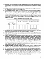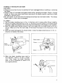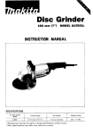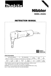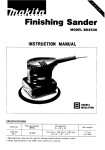
1
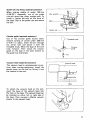
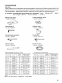
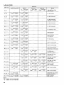
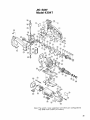
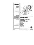
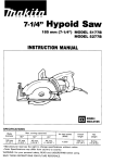
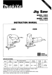
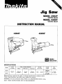
Jig Saw
MODEL 4304T
Variable Speed
MODEL 4305T
Variable Speed
INSTRUCTION MANUAL
~
43041
4305T
DOUBLE
INSULATION
SPECIFICATIONS
Length
Model
of stroke
Wood
Max. cutting capacities
Aluminum
Mild Steel
Strokes
per minute
4304T
.
4305T
26"
(1")
135"
(5-5116")
10mm
(318")
(:g/yg')
500
~
3,000
Overall
length
Net
weight
249 mm
19-3/4"1
287 mm
(11-5/16',)
2.4 kg
(5.3 Ibs)
Manufacturer reserves the right t o change specifications without notice.
Note: Specifications may differ from country t o country.
WARNING: For your personal safety, READ and UNDERSTAND before using.
SAVE THESE INSTRUCTIONS FOR FUTURE REFERENCE.
IMPORTANT
SAFETY INSTRUCTIONS
(For All Tools)
WARNING: WHEN USING ELECTRIC TOOLS, BASIC SAFETY
PRECAUTIONS SHOULD ALWAYS BE FOLLOWED TO REDUCE
THE RISK OF FIRE, ELECTRIC SHOCK, AND PERSONAL
INJURY, INCLUDING THE FOLLOWING:
READ ALL INSTRUCTIONS.
1. KEEP WORK AREA CLEAN. Cluttered areas and benches invite injuries.
2. CONSIDER WORK AREA ENVIRONMENT. Don't use power tools in damp
or wet locations. Keep work area well lit. Don't expose power tools t o rain.
Don't use tool in presence of flammable liquids or gases.
3. KEEP CHILDREN AWAY. All visitors should be kept away from work area.
Don't let visitors contact tool or extension cord.
4. STORE IDLE TOOLS. When not in use, tools should be stored in dry, and high
or locked-up place - out of reach of children.
5. DON'T FORCE TOOL. It will do the job better and safer at the rate for which
it was intended.
6. USE RIGHT TOOL. Don't force small tool or attachment t o do the job of a
heavy-duty tool. Don't use tool for purpose not intended; for example, don't
use circular saw for cutting tree limbs or logs.
7. DRESS PROPERLY. Don't wear loose clothing or jewelry. They can be caught
in moving parts. Rubber gloves and non-skid footwear are recommended
when working outdoors. Wear protective hair covering t o contain long hair.
8. USE SAFETY GLASSES. Also use face or dust mask if cutting operation is
dusty.
9. DON'T ABUSE CORD. Never carry tool by cord or yank it t o disconnect from
receptacle. Keep cord from heat, oil, and sharp edges.
IO. SECURE WORK. Use clamps or a vise t o hold work. It's safer than using
your hand and it frees both hands t o operate tool.
11. DON'T OVERREACH. Keep proper footing and balance at all times.
12. MAINTAIN TOOLS WITH CARE. Keep tools sharp and clean for better and
safer performance. Follow instructions for lubricating and changing accessories. Inspect tool cords periodically and if damaged, have repaired by authorized service facility. Inspect extension cords periodically and replace if
damaged. Keep handles dry, clean, and free from oil and grease.
13. DISCONNECT TOOLS. When not in use, before servicing, and when changing accessories, such as blades, bits, cutters.
2
14. REMOVE ADJUSTING KEYS AND WRENCHES. Form habit of checking t o
see that keys and adjusting wrenches are removed from tool before turning
it on.
15. AVOID UNINTENTIONAL STARTING. Don't carry tool with finger on switch.
Be sure switch is OFF when plugging in.
16. EXTENSION CORDS. Make sure your extension cord is in good condition.
When using an extension cord, be sure t o use one heavy enough t o carry
the current your product will draw. A n undersized cord will cause a drop
in line voltage resulting in loss of power and overheating. Table 1 shows the
correct size t o use depending on cord length and nameplate ampere rating.
If in doubt, use the next heavier gage. The smaller the gage number, the
heavier the cord.
TABLE 1
I
I
MINIMUM GAGE FOR CORD SETS
Total Length of Cord in Feet
0 - 25
I
26
- 50
I
51 - 100
I
101
- 150
Ampere Rating
Not More
More
Than
Than
0
6
10
-
12
-
-
6
10
12
16
18
18
16
14
16
16
16
12
16
14
14
14
12
12
Not Recommended
17. OUTDOOR USE EXTENSION CORDS. When tool is used outdoors, use only
extension cords intended for use outdoors and so marked.
18. STAY ALERT. Watch what you are doing, use common sense. Don't operate
tool when you are tired.
19. CHECK DAMAGED PARTS. Before further use of the tool, a guard or other
part that is damaged should be carefully checked t o determine that it will
operate properly and perform its intended function. Check for alignment of
moving parts, binding of moving parts, breakage of parts, mounting, and any
other conditions that may affect its operation. A guard or other part that
is damaged should be properly repaired or replaced by an authorized service center unless otherwise indicated elsewhere in this instruction manual.
Have defective switches replaced by authorized service center. Don't use
tool if switch does not turn it on and off.
20. GUARD AGAINST ELECTRIC SHOCK. Prevent body contact w i t h grounded
surfaces. For example; pipes, radiators, ranges, refrigerator enclosures.
21. REPLACEMENT PARTS. When servicing, use only identical replacement parts.
22. POLARIZED PLUGS. To reduce the risk of electric shock, this equipment has
a polarized plug (one blade is wider than the other). This plug will fit in a
polarized outlet only one way. If the plug does not fit fully in the outlet,
reverse the plug. If it still does not fit, contact a qualified electrician t o install
the proper outlet. Do not change the plug in any way.
3
VOLTAGE WARNING: Before connecting the tool t o a power source (receptacle,
outlet, etc.) be sure the voltage supplied is the same as that specified o n the
nameplate of the tool. A power source with voltage greater than that specified
for the tool can result in SERIOUS INJURY t o the user - as well as damage t o
the tool. If in doubt, DO NOT PLUG IN THE TOOL. Using a power source with
voltage less than the nameplate rating is harmful t o the motor.
ADDITIONAL SAFETY RULES
1. Avoid cutting nails. Inspect for and remove all nails from the workpiece before
operation.
2. Don't cut hollow pipe.
3.Do not cut oversize workpiece.
4. Check for the proper clearance beneath the workpiece before cutting so that
the blade will not strike the floor, workbench, etc.
5. Always wear eye protection conforming with current national standard.
Severe eye injury could result.
6. Hold the tool firmly.
7. Make sure cord is out of your way and not in the line of cut.
8. Make sure the blade is not contacting the workpiece before the switch is
turned on.
9. Keep hands away from moving parts.
.
IO. When cutting through
walls, floors or wherever "live" electrical wires may
be encountered, DO NOT TOUCH ANY METAL PARTS OF THE TOOL!
Hold the tool only by the insulated grasping surfaces t o prevent electric shock
if you cut through a "live" wire.
11. Do not leave the tool running. Operate the tool only when hand-held.
12.Always switch off and wait for the blade t o come t o a complete stop before
removing the blade from the workpiece.
13.Do not touch the blade or the workpiece immediately after operation; they
may be extremely hot and could burn your skin.
SAVE THESE INSTRUCTIONS.
4
,
Installing or removing the saw blade
CAUTION :
.Always be sure that the tool is switched off and unplugged before installing or removing
the blade.
.Always clean off the blade and blade holder before installing the blade. Chips or foreign
matter on them may cause insufficient securing of the blade, possibly resulting in blade
breakage or serious injury.
0 Do not switch on the tool with the clamp protruding from the blade holder. The clamp,
blade holder or roller may be damaged.
For 4304T
1. Pull the blade installing lever in the @ direction until it stops while lifting it slightly.
2. Rotate the blade installing lever in the @ direction and the clamp on the blade holder
will open. Open the clamp a l i t t l e more than the thickness of the blade to be installed.
3. With the blade teeth facing forward, insert the blade into the blade holder as far as it
will go. Make sure that the back edge of the blade fits properly into the groove of the
ro Iler .
4. With the blade held against the blade holder, rotate the blade installing lever in the @
direction to tighten the clamp.
Blade holder
Roller
5. With the blade installing lever held ii"
this position, move it in the @ direction. Then rotate the blade installing
lever in the @ direction to return it to
i t s original position.
5
For 4305T
1. Press the button to raise the blade installing knob.
2. Rotate the blade installing knob in the 0 direction and the clamp on the blade holder
will open. Open the clamp a l i t t l e more than the thickness of the blade to be installed.
3. With the blade teeth facing forward, insert the blade into the blade holder as far as it
will go. Make sure that the back edge of the blade f i t s properly into the groove of the
roller.
4. With the blade held against the blade holder, rotate the blade installing knob in the @
direction to tighten the clamp.
Blade installing knob
Button
Blade holder
Roller
5. With the blade installing knob kept in this position, push it back down to i t s original
position.
NOTE : Occasionally lubricate the roller.
Selecting the cutting action
This tool can be operated with an orbital
or a straight line cutting action. To change
the cutting action, just turn the lever to the
desired cutting action position. Refer to
the table below to help determine the
appropriate cutting action.
I
Position
I
I
6
111
Small orbit cutting action
I
I
Large orbit cutting action
For cutting mild steel, aluminum and hard wood
For cutting wood and plywood.
For fast cutting in aluminum and mild steel.
Medium orbit cutting action
I1
I
For cutting mild steel, stainless steel and plastics.
For clean cuts in wood and plywood.
Straight line cutting action
0
1
Applications
Cutting action
I
For fast cutting in wood and plywood.
Switch action
For 4304T
CAUTION :
Before plugging in the tool, always check to see that the switch trigger actuates properly
and returns to the "OFF" position when released.
To start the tool, simply pull the trigger.
Release the trigger to stop. For continuous
operation, pull the trigger and move the
lock lever backward. To stop the tool from
the locked position, pull the trigger fully,
then release it.
ILock lever
Switch trigger
For 4305T
CAUTION:
Before plugging in the tool, always check to see that the switch actuates properly.
To start the tool, slide the switch lever
forward. Slide the switch lever backward
to stop.
Speed adjusting dial
The tool speed can be adjusted and maintained between 500 and 3,000 strokes per
minute by turning the adjusting dial. The dial i s marked 1 (lowest speed) to 6 (full speed).
For 4304T
For 4305T
Speed adjusting dial
I
Speed adjusting dial
Refer to the table a t right to Select the Proper speed for the workpiece to be cut.
However, the appropriate speed may differ
with the type or thickness of the workpiece. In general, higher speeds will allow
you to cut workpieces faster but the
service life of the blade will be reduced.
Mild Steel
Stainless Steel
Aluminum
Plastics
CAUTION :
Adjust the speed adjusting dial only within the range of numbers 1 through 6. Do not
force the dial beyond this range or damage to the tool may result.
Cutting operation
CAUTION :
0 Always hold the tool with the base flush with the workpiece. Failure to do so may cause
a slanted cutting surface and blade breakage.
.Advance the tool very slowly when cutting curves or scrolling. Forcing the tool may
cause a slanted cutting surface and blade breakage.
Turn the tool on without the blade making
any contact. Rest the base flat on the
workpiece and gently move the tool forward along the previously marked cutting
line.
Cutting line
Bevel cutting
CAUTION :
Always unplug the tool before making any adjustments.
' and 45' (left or
With the base tilted, you can make bevel cuts at any angle between 0
right). Loosen the base securing lever and move the base so that the dent mark in the
motor housing is aligned with the slot in the base. Tilt the base until the desired bevel
angle i s obtained. The edge of the motor housing indicates the bevel angle by graduations.
Then tighten the base securing lever to secure the base.
NOTE :
Always remove the plastic cover (chip shield) from the tool when you make bevel cuts
using an optional guide rule (rip fence) or circular guide.
. Base securing
lever
8
Flush cutting
Loosen the base securing lever and slide the
base all the way back. Then tighten the
base securing lever to secure the base.
cutouts
Cutouts can be made with either of two methods A or B.
A) Boring a starting hole:
For internal cutouts without a lead-in
cut from and edge, pre-drill starting hole
more than 12 mm (15/32") in diameter.
Insert the blade into this hole and hold
the tool firmly against the workpiece
to start your cut.
\
,
,
/
B) Plung cutting:
You need not bore a starting hole or
make a lead-in cut if you carefully do
as follows:
1. Tilt the tool up on the front edge of
the base, with the blade point positioned just above the workpiece surface.
2. Apply firm pressure to the tool so
that the front edge of the base will
not move when you switch on the
tool and gently lower the back end
of the tool slowly.
3. As the blade slices into the workpiece, slowly lower the base of the tool down onto
the workpiece surface.
4. Complete the cut in the normal manner.
9
Finishing edges
/
/
To trim edges or make slight dimensional
adjustments, run the blade lightly along the
cut edges.
Metal cutting
Always use a suitable coolant (cutting oil) when cutting metal. Failure to do so will cause
significant blade wear. The underside of the workpiece can be greased instead of using a
coolant.
Plastic base plate
Use the plastic base plate when cutting decorative veneers, plastics, etc. l t protects
sensitive or delicate surfaces from damage.
To replace the base plate, remove the four
screws.
Screw
ic base plate
I
Anti-splintering device
To reduce the potential for workpiece
surface splintering, the anti-splintering
device can be used. Fit it into the base
from below so that it surrounds the sides
of the blade.
I
ef
ase
Anti-splintering device
10
Guide rule (rip fence; optional accessory)
When cutting widths of under 150 mm
(5-29/32") repeatedly, use of the guide
rule will assure fast, clean, straight cuts. To
install it, loosen the bolt on the front of
the base. Slip in the guide rule and secure
the bolt.
Hex wrench
Bolt
Guide rule
Circular guic, (optional accessory
Use of the circular guide insures clean,
smooth cutting of circles under 200 mm
(7-7/8") in radius. Insert the pin through
the center hole and secure it with the
threaded knob. Move the base of the tool
fully forward. Then install the circular
guide on the base in the same manner as
the guide rule (rip fence).
Vacuum head (optional accessory)
The vacuum head is recommended to perform clean cutting operations. Install the
plastic cover on the tool by fitting it into
the notches in the tool.
Y
0
Threaded knob
guide
&Circular
1
7
-
Vacuum head
I
Base
To attach the vacuum head on the tool,
insert the hook of the vacuum head into
the hole in the base. The vacuum head can
be installed on either left or right side of
the base. Then connect a Makita vacuum
cleaner to the vacuum head.
11
MAINTENANCE
CAUTION:
Always be sure that the tool i s switched off and unplugged before attempting to perform
inspection or maintenance.
Cleaning the clamp on the blade holder
If chips or foreign matter get into the clamp on the blade holder, clean out the clamp
after removing it from the blade holder. To remove the clamp, rotate the blade installing
lever (for 4304T) or knob (for 4305T) in the blade loosening direction as far as it will go.
Then remove the clamp from the blade holder while rotating the clamp counterclockwise. To install the clamp, first make sure that the blade installing lever (for 4304T) or
knob (for 4305T) has been rotated in the blade loosening direction as far as possible.
Insert the clamp into the blade holder while rotating it clockwise one quarter to one full
turn. Grasp the clamp with your fingers so that it will not turn, then rotate the blade
installing lever or knob in the blade tightening direction so that the clamp will go into the
blade holder.
8
Blade holder
Clamp
To maintain product SAFETY and RELIABILITY, repairs, any other maintenance or
adjustment should be performed by Makita Authorized or Factory Service Centers,
always using Makita replacement parts.
12
ACCESSORIES
CAUTION:
These accessories or attachments are recommended for use w i t h your Makita tool specified in this
manual. The use of any other accessories or attachments might present a risk of injury t o persons.
The accessories or attachments should be used only in the proper and intended manner.
A n exception: Universal shank jig saw blades w i t h a thickness of 1 m m - 1.25 m m (1/32" - 3/64")
and a length of 58 m m - 8 2 m m ( 2 - 9 / 3 2 " - 3 - 7 / 3 2 " ) .
Plastic base plate
Anti-splintering device
Part No. 41 5537-8
Part No. 41 5524-7
Plastic cover
*Hex wrench 3
Part No. 41 5525-5
Part No. 783201-2
r
Circular guide assembly
Guide rule
Part No. 123030.5
Part No. 1641 13-2
Vacuum head
Hose 19 - 2.5
Part No. 192418-0
Part No. 192108.5
Jig saw blade (Packed 5 each)
'lade
NO.
type
51
I
Part No'
I
pz?i:h
I
Effective cutting
blade length
I
792428-3
I
24
I
6 5 mm i2-1/2")
No. 58
792429 1
8
No. 59
792430-6
8
EO mm 13-1/8"1
No. 6-10
792529-7
9
80 mm 13-l/E"l
No. 6-11
No. 6-12
No. 6 - 1 3
I
I
I
No. 8-14
NO.
6-16
NO.
6-17
792463-1
792464~9
792465-7
1
1
I
792466-5
1
I
792468-1
792469-9
9
6
8
80 mm (3-1/8")
1
1
I
13-1/6"1
80 mm (3-118")
50"
18
I
I
75 mm 13")
80"
12")
6
I
80 mm 13-1/8"1
6
I
70 mm 12-314")
(Note)
Refer to the next page for "Application" of each blade.
13
Jig saw blade
Application
Blade type
Feature
Wood and plywood
Plastics
Aluminum
Mild steel
No. 51
-
1.5 - 3 mm thick
11/16'' - 118")
1 - 6 mm thick
13/64" - 1/4"l
1 - 3 mm thick
(3164'' - 1/8"l
No. 58
4 - 60 mm thick
15/32" - 2 318")
4 - 60 mm thick
15/32" - 2-318")
-
-
For fast cutting.
No 59
4 - 30 mm thick
15/32" - l - l / 8 " 1
-
For fast finish work
-
For fast finish work,
especially in plywood.
-
For fast finish work
-
For fast finish work
-
-
For roughing-in work.
-
-
Ideal for cutting
thin materials.
~
H
Also ideal for cutting
stainless steel.
9
~~
4 - 30 mm thick
15/32" - l - l / 8 " l
S
-
I
No. 6 - 1 0
No. 8- 11
3 - 3 0 mm thick
1118" - 1-118"I
3
50 mm thick
I l W ' - 2")
S
-
-
I
No. 8-12
No. 8 - 1 3
4 - 60 mm thick
15/32" - 2-318")
4 - 60 mm thick
15132" - 2-318")
S
No. 8 - 1 4
2 - 3 0 mm thick
15/64, - 1-118"l
No. B- 15
3 - 3 0 m m thick
1118" - 1-1/8"1
2 - 30 mm thick
15/64' - l - l / E " I
H
3 - 30 mm thick
11/8" - 1-118"l
I
No. 8 - 1 6
5 - 60 m m thick
113164' - 2-318")
No. 8-17
5 - 60 mm thick
I13 / 6 4 ' - 2-3/8"1
H
5 - 60 mm thick
113/64' - 2-318")
S
I
2 - 3 0 mm thick
15/64' - 1-118")
No. 8 - 1 9
3 - 3 0 mm thick
1118" - 1~1/8")
-
No. 8 - 2 2
-
-
-
2 - 30 mm thick
15/64" - 1 1/8"1
I
3 - 30 mm thick
1118" - 1 ~ 1 / 8 " )
H
-
Ideal for scroll cutting
-
-
Cuts on down stroke.
Splinter-free on finish side
3 - 10 mm thick
1118" - 318")
-
For finish work,
especially in plastics.
1 - 6 mm thick
(3164' - 1/4"l
1 - 3 mm thick
13/64" - 1/8"l
Also ideal for cutting
stainless steel.
3 - 6 mm thick
(118" - 1/4'1
H
3 - 10 mm thick
1118'' - 318")
3 - 6 mm thick
1118'' - 1/4"l
Also ideal for cutting
stainless steel.
1 - 3 mm thick
(3164'' - 118"I
0.5 - 3 mm thick
(1164'' - 118")
0.5 - 2 mm thick
(1164'' - 5/64,')
Also ideal for cutting
stainless steel.
3 - 30 mm thick
1118" - 1-1/8"1
3 - 10 mm thick
1118'' - 318")
Ideal for cutting
thick materials.
3 - 30 mm thick
1118" - 1 118")
3
3 - 55 mm thick
1118'' - 2-118"l
H
1.5 - 3 mm thick
11/16" - 118")
U
No. 8 - 2 3
-
No. 8 - 2 4
-
No. 8 - 2 5
No. 8 - 2 6
H
3 - 55 mm thick
1118'' - 2-118")
3 - 55 mm thick
1118'' - 2-118")
H
H
3 - 55 mm thlck
11/8" - 2-118")
H
3 - 55 mm thick
1118'' - 2 118")
H
- 3 mm
thick
l
1.5
11/16,,
No. 8-27
-
1
5 - 60 mm thick
113/64" - 2 318")
-
No. 8-16L
5-llOmmthick
113164' - 4-5/16',)
5-11Ommthick
113164' - 4-5/16"1
"H"
"S"
14
stands for hard materials
s t a n d s for soft m a t e r i a l s
I
1 - 6 mm thick
13/64" - 114")
I
- 10 mm thick
11/8" - 3/8"l
1 - 3 mm thick
13/64" - 118")
Ideal for scroll cutting
Ideal for scroll cutting.
H
No. BR- 13
NOTE:
For fast cutting.
Ideal for scroll cutting.
s
4
No. 8-21
Ideal for cutting
thin materials.
5 - 60 mm thick
I 13/64" - 2-318")
~
No. 6-18
I
-
-
-
Splinter-free cuts in wood,
requiring no sanding.
-
Ideal for cutting
thick materials.
JIG SAW
Model 4304T
Note: The switch, noise suppressor and other part configurations
may differ from country to country.
15
ITEM
NO.
NO.
USE0
MACHINE
1
2
3
4
5
6
7
8
9
10
11
12
14
15
16
17
18
19
20
21
22
23
24
25
26
27
28
29
30
31
32
33
34
35
36
37
38
39
40
41
42
43
44
45
46
47
1
1
1
1
1
1
1
1
1
1
1
1
2
1
1
1
1
1
1
1
1
1
1
1
1
1
1
1
1
1
1
1
1
1
1
1
2
2
1
2
1
1
1
1
1
1
-
$2D
DESCRIPTION
MACHINE
~
Pan Head Screw M4x8 [With Washer1
Handle Set [With Item 441
Lever 51
Inner Level
Compression Spring 4
Caution Label
Lock On Lever
Spacer
Switch
Controller
PI" 3
Switch Lever
Tapping Screw 4x18
Strain Relief
Cord Guard
Tapping Screw Flange PT 4x20
Cord
Gear Shaft
Flat Washer 8
Needle Bearing 810
Helical Gear 51
Needle Bearing 810
Flat Washer 26
Push Plate
Balance Plate
Balance Plate
Flat Washer 26
Crank Complete
Needle Bearing 607
Thrust Plate
Slider
Holder
Gear Housing Cover Complete
CO"WCt0,
Joint
Driver Rod
Tapping Screw CT 4x16
Tapping Screw Flange PT 4x20
Retainer Complele
Tapping Screw PT 4x35
P," 4
Tapping Screw Flange PT 4x35
Handle Set IWith Item 21
Rod
Blade Fix
Slide Plate
48
49
50
51
52
53
54
55
56
57
58
59
60
61
62
63
64
65
66
67
68
69
70
71
72
73
74
75
76
77
78
79
80
81
82
83
84
85
86
87
88
89
90
91
92
2
1
2
2
1
1
2
1
1
3
1
1
1
1
1
1
1
1
1
1
1
1
1
1
1
4
1
2
2
1
1
2
1
1
1
1
1
1
1
2
1
1
1
1
1
- -
Note The switch and other part ~ p e ~ i f i ~ a tmay
i o n differ
~
from country to country
16
DESCRIPTION
Compression Spring 4
Stop Ring E - 3
Countersunk Head Screw M4x10
Hex Socket Head Bolt M4x16
Retaining Ring 5 - 8
Packing
Tapping Screw Flange PT 4x20
Flat Washer 6
Gem Housing
Pan Head Screw M4x10 [With Washer)
Flat Washer 6
Flat Washer 5
Lever 65
Hex Bolt M5x24
Nut M6
Ball Bearing 608LLB
Fan 54
ARMATURE ASSEMBLY
IWith Item 63. 6 4 66 & 671
Insulation Washer
Ball Bearing 607LL8
Rubber Ring 19
Base
Clamp Plate
Hex Nut M I
Pan Head Screw M4x8 IWith Washer1
Countersunk Head Screw M 5 x 8
Base Plate
Carbon Brush
Brush Holder
Choke Coil
Name Plate
Tapping Screw Flange PT 4x30
Rear Cover
Makita Label
Cap
Motor Housing
Field
All cap
Baffle Plate
Tapping Screw Flange PT 4x60
Lever 17
Compression Spring 4
Steel Ball 4
Stop Ring E - 5
Rubber Pm 4
JIG SAW
Model 4305T
Note: The switch, noise suppressor and other part configurations
may differ from country to country.
17
'iiM
MACHINE
DESCRIPTION
MACHINE
~
1
2
3
4
5
6
7
8
9
10
I t
12
13
14
15
16
17
18
19
20
21
22
23
24
25
26
27
28
29
30
31
32
33
34
35
36
37
38
39
40
41
42
43
44
&
!,
~
1
1
1
1
1
1
1
1
1
1
1
1
1
1
1
1
1
1
1
2
1
1
1
1
1
1
2
2
1
1
1
1
2
1
2
2
1
1
2
1
1
3
1
1
Head Cover Set IWith Item 261
Gear Shaft
Flat Washer 8
Needle Bearing 8 1 0
Helical Gear 51
Needle Bearing 8 1 0
Flat W s h e r 2 6
Push Plate
Balance Plate
Balance Plate
Flat Washer 2 6
Crank Complete
Needle Bearing 601
Thrust Plate
Slider
Holder
Gear Housing Cover Complete
Joint
Driver Rod
Tapptng Screw CT 4x16
Retainer Complete
PO" 5
Lift Button
Knob
Box Wrench
Head Cover Set [With Item 11
Tapping Screw Flange PT 4x35
Tapping Screw PT 4x55
P," 4
Rod
Blade Fix
Slide Plate
Compression Spring 4
Stop Ring E - 3
Countersunk Head Screw M4x10
Hex Socket Head Bolt M4x16
Retaining Ring 5 - 8
Packing
Tapping Screw Flange PT 4x20
Flat Washer 6
Gear Housing
Pan Head Screw M4x10 (With Washer1
Flat Washer 6
Flat Washer 5
45
46
47
48
49
50
51
52
53
54
55
56
57
58
59
60
61
62
63
64
65
66
67
68
69
70
71
72
73
74
76
77
78
79
80
82
82
83
84
85
86
87
88
1
1
1
1
1
1
1
1
1
1
1
1
1
1
4
1
1
1
1
1
1
1
1
2
1
1
1
1
2
1
2
2
1
1
1
1
1
2
1
1
1
1
1
Note: The Switch and other part specifications may dbffer from country to countrv.
Lever 6 5
Hex Bolt M 5 ~ 2 4
Nut M 6
Rubber Pin 4
Ball Bearing 608LLB
Fan 5 4
ARMATURE ASSEMBLY
lWtth Item 49. 50. 52 & 531
Insulatton Washer
Ball Bearing 607LLB
Rubber Ring 19
Base
Clamp Plate
Hex Nut M 5
Pan Head Screw M4xB IWith Washer)
Countersunk Head Screw M5x8
Base Plate
Switch Rod
Switch
SUppOrt
Terminal Block 2P
Controller
Rear Covet
Name Plate
Tapping Screw Flange PT 4x60
Makita Label
Cord
Cord Guard
Choke Coil
Tapping Screw 4x18
Strain Relief
Brush Holder
Carbon Brush
Motor Housing
Switch Lever
Field
Air Cap
Bsffle Plate
Tapping Screw Flange PT 4x60
Lever 17
Compression Spring 4
Steel Ball 4
Stop Ring E - 5
Caution Label (Not Illustratedl
19
MAKCTA LM
I CTED ONE YEAR WARRANTY
Warranty Policy
Every Makita tool is thoroughly inspected and tested before leaving the factory. It is warranted to
be free of defects from workmanship and materials for the period of ONE YEAR from the date of
original purchase. Should any trouble develop during this one-year period, retum the COMPLETE
tool, freight prepaid, to one of Makita’s Factory or Authorized Service Centers. If inspection shows
the trouble is caused by defective workmanship or material, Makita will repair (or at our option,
replace) without charge.
This Warranty does not apply where:
repairs have been made or attempted by others:
a repairs are required because of normal wear and tear:
a The tool has been abused, misused or improperly maintained ;
alterations have been made to the tool.
IN NO EVENT SHALL MAKlTA BE LIABLE FOR ANY INDIRECT, INCIDENTAL OR CONSEQUENTIAL DAMAGES FROM THE SALE OR USE O F THE PRODUCT. THIS DISCLAIMER
APPLIES BOTH DURING AND AFTER THE TERM OF THIS WARRANTY.
MAKlTA DISCLAIMS LIABILITY FOR ANY IMPLIED WARRANTIES, INCLUDING IMPLIED
WARRANTIES OF “MERCHANTABILITY” AND “FITNESS FOR A SPECIFIC PURPOSE,”
AITER THE ONE-YEAR TERM O F THIS WARRANTY.
This Warranty gives you specific legal rights, and you may also have other rights which vary from
state to state. Some states do not allow the exclusion or limitation of incidental or consequential
damages, so the above limitation or exclusion may not apply to you. Some states do not allow
Limitation on how long an implied warranty lasts, so the above limitation may not apply to you.
MAKlTA MANUFACTURING EUROPE LTD
ROAD 7, HORTONWOOD INDUSTRIAL ESTATE
TELFORD, SHROPSHIRE TF1 4GP
004032-065