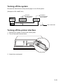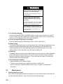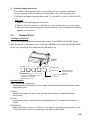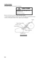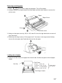
1
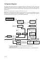
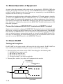
Back OPERATOR'S MANUAL GMDSS Radio Station Model RC-1800F/1800T This manual covers the general description of the GMDSS Radio Station. Refer to the separate manuals for detailed information on individual units mounted in the console. www.furuno.com i TABLE OF CONTENTS Chapter 1 INTRODUCTION 1.1 Operational Overview ....................................................................................... 1-1 1.2 System Diagram ............................................................................................... 1-2 1.3 Equipment. Description..................................................................................... 1-3 1.4 Mutual Operation of Equipment ........................................................................ 1-4 1.5 Power On/Off .................................................................................................... 1-4 Chapter 2 MAINTENANCE 2.1 Control Panel .................................................................................................... 2-1 2.2 Maintenance ..................................................................................................... 2-4 2.3 Printer PP-510 .................................................................................................. 2-5 2.4 Replacement of the Parts ................................................................................. 2-8 SPECIFICATIONS........................................................................................... SP-1 ii Chapter 1 INTRODUCTION 1.1 Operational Overview The RC-1800F/1800T radio rack console conforms to the IMO regulations for GMDSS radio equipment. It contains an SSB radiotelephone, DSC terminal, NBDP terminal and Inmarsat C mobile earth station. The RC-1800F is operated with the control panel and the dimmer knob. You can monitor the AC mains source by the Lamp. Power can be checked with the power meter. The RC-1800T is operated with the control panel and the dimmer knob (option). 1–1 1.2 System Diagram The figure below shows the system diagram for the RC-1800F/1800T. The RC-1800 series GMDSS Radio Station consists of two models' RC-1800F (floor deck mount) and 1800T (tabletop mount). Equipment are controlled using FURUNO’s radio interface protocol called MIF (see note below). The type and number of the component differ from set to set. Note: MIF is a handshaking type signal exchange protocol developed by FURUNO for remote control of radio equipment. In the RC-1800F/1800T, for example, the MF/HF DSC terminal can automatically set the frequency on the SSB Radiotelephone. RC-1800F/1800T SSB Radiotelephone Inmarsat-C 24VDC 24VDC NMEA OUT (Maximum five outputs) NMEA IN (Nav data) Distribution PCB PP-510 (Inside Console) 24VDC (Printer) RC-1800F only, built in console 24VDC (To each unit) DSC Terminal* PP-510 24VDC (Printer) IF-8500 (Printer Interface) 24VDC NBDP Terminal** AC/DC Power Supply 24VDC 24VDC 100/110/ (Reverse 220/440VAC Source) (Main Source) (Inside Console) No.1 FM-8500 No.2 FM-8500 External VHF Radiotelephone (Including DSC) Radio Battery Alarm Unit (Option) (Distress Alert Unit) *: May be incorporated in the SSB radiotelephone depending on radiotelephone used. **: NBDP terminal is not incorporated in the dual Inmarsat C radio rack console. 1–2 1.3 Equipment Description Regulations require that all equipment be powered while the vessel is underway. SSB Radiotelephone For ship-ship and ship-station radio communications in the MF/HF band (1.6-26.175 MHz), the main communications modes are; • Voice communications (J3E) via the handset • DSC communications (Telex:J2B) by the MF/HF DSC terminal • Telex communications by the NBDP terminal (J2B) DSC and NBDP functions may or may not be incorporated in the SSB radiotelephone depinding on radiotelephone used. MF/HF DSC Terminal DSC function is incorporated in SSB Radiotelephone. However DSC terminal may also carry the DSC function. The MF/HF DSC Terminal has many functions. Below are its main functions. • Distress alert: Transmit the distress alert via the SSB Radiotelephone. • Watches DSC distress and safety frequencies. The MF/HF DSC Terminal receives distress alert from vessel in distress and all ships call (safety and urgent call) from ship or coast station. • All Ships Call: For urgent situation on own ship (for example, request for medical assistance). • Individual Call: Place a call to a specific ship or coast station. NBDP Terminal NBDP function is incorporated in the SSB radiotelephone. However, NBDP terminal may also carry the NBDP function. The NBDP Terminal provides Telex communications with coast stations over the MF/HF band via the SSB Radiotelephone. Furthermore, it can receive MSI (Maritime Safety Information) messages via the SSB Radiotelephone (Scan reception). Note) NBDP Terminal is not incorporated in the dual Inmarsat C type radio rack console. Inmarsat-C Mobile Earth Station Provides distress and general Telex communications for mobile and fixed terrestrial subscribers in the Inmarsat-C communications network. Telex messages are processed by what is known as store-and-forward Telex. A Telex message transmitted by you arrives at a coast station where it is stored temporarily and then delivered to the subscriber specified. (Full duplex communications are not possible.) AC/DC Power Supply The AC/DC Power Supply consists of a battery charger and two rectifiers (PR-850AR and PR300) which can accept both AC and DC powers (RC-1800F only). For RC-1800T the AC/DC Power Supply is installed externally. In the event of main AC power failure, auxiliary power (battery) provides power to the equipment, for the amount of time stipulated by radio regulations. 1–3 1.4 Mutual Operation of Equipment As noted earlier, the equipment in this radio console are interfaced by FURUNO's MIF radio interface. For example, to transmit a message over the MF/HF DSC Terminal or NBDP Terminal, the Tx and Rx frequencies and class of emission are automatically set on the SSB Radiotelephone and then the message is transmitted. Two printers are supplied and one is dedicated to the Inmarsat C. The other printer is shared by up to four units: MF/HF DSC Terminal, NBDP Terminal, and external VHF DSC (maximum two sets, option). It is automatically connected to one of those equipment on a first-come-firstserved basis. For example, if the MF/HF DSC Terminal is used (message transmission or reception), the printer is automatically connected to the MF/HF DSC Terminal and disconnects itself from other equipment. Connection between MF/HF DSC Terminal and NBDP Terminal Suppose you transmitted a call over the MF/HF DSC Terminal and want to communicate with the receiving station by the NBDP Terminal instead of the SSB Radiotelephone. If the MF/HF DSC Terminal and NBDP Terminal were not connected you would have to set the several data such as working frequency, communication mode, etc. manually on the NBDP Terminal. Because they are connected by the remote function, however, the data mentioned above are automatically set on the NBDP Terminal via the MF/HF DSC Terminal. 1.5 Power On/Off Turning on the system For RC-1800F use the power switch at the lower left side of the console. For RC-1800T use main switch on the switchboard and power switch on each AC/DC power supply. 1. Turn on breakers and switches on the AC/DC Power Supply in the following order: 1 100/200 VAC main power switch 2 PR-850AR AC input breaker 3 PR-850AR DC output breaker 4 All toggle switches (any order) on right side 2. Turn on power switches (any order) of all equipment in the console. 3PR-850AR DC Output Breaker 4Toggle Switches PR-850AR AC MAIN 24VDC OUT (BACK UP) AC IN 1Main Switch 2PR-850AR AC Input Breaker 1–4 Turning off the system Reverse the order shown at the previous page to turn off the system. (Example for RC-1800F-15A) Battery Charger Inmarsat C (24 VDC backed up by battery) FS-1570 (24 VDC backed up by battery) PR-850AR PR-300 24 VDC Battery 100/110/220 VAC (Main Switch) Turning off the printer interface 1. Remove four screws to remove the control panel. 2. Turn off the switch shown below. IF8 I 500 ON OF F 3. Attach the control panel. 1- 5 This page is intentionally left blank. Chapter 2 MAINTENANCE 2.1 Control Panel The figure which follows is an exploded view of the Control Panel. 4 3 STOP 5 BUZZER switch Dimmer knob: right side of console (refer to page 1-1) (RC-1800T: option) Voltmeter and Ammeter 2 EMG LIGHT 1 switch BATTERY MONITOR lamp 6 BATTERY CHARGER switch For flooded lead-acid battery: Control description 1. EMG LIGHT switch Turns the emergency lamps at the top of the console on/off (RC-1800T: option). 2-1 2. BATTERY MONITOR lamp IN USE lamp (AC power failure: orange) Lights to alert that the AC power has failed and the radio equipment is being powered by the radio battery (DC power) alone. When lit, only the equipment related to distress communication are powered. (Power is not supplied to console lights.) LOW VOLT lamp (low battery voltage: red) Lights to alert that the battery voltage is below 22 VDC. (The aural alarm sounds until the voltage becomes higher than 22 VDC.) 3. Voltmeter, Ammeter Monitors battery voltage and electric current during charging of radio battery. The battery voltage is kept between 25.0 VDC and 28.0 VDC in the flooded lead-acid battery (traditional), and 26.7 VDC in the valve-regulated lead-acid battery. 4. Dimmer knob Turns on the desk lamp and adjusts lamp brilliance, and is located at the top of the console. The desk lamp does not light during AC power failure; use the emergency light instead. 5. BUZZER STOP switch This switch silences the buzzer. The buzzer sounds when the battery is abnormal or AC power fails. 6. BATTERY CHARGER switch Valve-regulated lead-acid battery (maintenance free battery) • AUTO: Set the switch to AUTO always. The battery voltage is kept between 26.5 VDC and 27.0 VDC. • OFF: Disconnects the charger from the radio battery. 1)Care of the battery The lead-acid battery powers the radio console when the ship’s mains power and emergency power fail, to enable communication in the event of distress. Therefore, follow the points mentioned below to keep the battery in good working order. WARNING Do not remove or disassemble the safety tap of the lead-acid battery. Removal may cause the battery to explode, lower its performance or shorten its life. The temperature of the electrolyte in the lead-acid battery should keep between -15°C and 45°C. The electrolyte can cause explosion if it becomes too hot. 2-2 2) Confirming charging Confirm that the BATTERY CHARGER switch on the Control Panel is set to AUTO. Further, confirm that the voltage shown on the battery voltage meter on the Control Panel is normal (between 26.5 VDC and 27.0 VDC). 3) Cleaning The battery and the area around it should always be clean and dry. Clean the battery case with a water-moistened cloth. Do not use organic solvents, thinner, gasoline, benzine or alcohol to clean the battery. (They may crack the case.) For heavy dirt, clean the case with white kerosene. 4) Environmental conditions • Keep the battery out of direct sunlight. • Coat the nuts and bolts which tighten the battery contacts with anticorrosive paint. Check the battery once a year, retighten nuts and bolts if necessary. Flooded lead-acid battery (traditional battery) Turns the battery charger on/off. • AUTO: Automatically turns on the battery when the battery voltage is below 25.0 VDC and turns it off when the voltage exceeds 28.0 VDC. While the vessel is underway, set the switch in this position. • OFF: Disconnects the charger from the radio battery. • MANUAL: Charges the battery manually. NOTE: When the charging current falls below 2A, wait for about 10 hours and then turn off the switch. (For details, see the manual for the lead-acid battery.) 1) Charging the battery Before operating the radio, check the voltage and current of the battery. When the BATTERY CHARGER on the Control Panel is set to AUTO, the battery voltage is kept between 25.0 VDC and 28.0 VDC. If the BATTERY CHARGER switch is kept in the OFF position for a long time the voltage may fall below 24 VDC. In this case, charge the battery as follows. 1. Set the BATTERY CHARGER switch to MANUAL. The charging current is around 20 A at the start, and is reduced gradually as charging proceeds. 2. When the charging current goes below 2 A, wait for about 10 hours and then turn the BATTERY CHARGER switch off or set it to AUTO. NOTE: When the AC power fails, the radio battery automatically supplies power to the radio regardless of BATTERY CHARGER switch position. The battery will not discharge as long as the AC power is alive. 2) Care of the battery The lead-acid battery powers the radio console when the ship’s main power and emergency power fail, to enable communication in the event of distress. Therefore, follow the points mentioned below to keep the battery in good working order. 2-3 WARNING Keep sparks and lit smoking materials away from the lead-acid battery. Make sure the battery room is well ventilated. The battery emits hydrogen gas which can cause explosion. The electrolyte in the lead-acid battery contains sulfuric acid, which can be harmful to the human body, particularly to the eyes. If sulfuric acid contacts eyes, skin or clothing, flush directly with water. For eyes, contact a physician. Loss of eyesight can result. The temperature of the electrolyte in the lead-acid battery should not exceed 45°C. The electrolyte can cause explosion if it becomes too hot. 3) Confirming charging Confirm that the BATTERY CHARGER switch on the Control Panel is set to AUTO. Further, confirm that the voltage shown battery voltage meter on the Control Panel shows is normal (between 25.0 VDC and 28.0 VDC). 4) Check the specific gravity of electrolyte Keep the specific gravity of electrolyte within 1.240 ± 0.010 (20°C). 5) Water supply The optimum electrolyte level is such that water fills to the highest graduation on the scale at the side of the battery case. When the electrolyte level falls below the highest graduation, fill to the highest graduation with distilled water. Do not use diluted sulfuric acid or tap water; they will shorten battery life. 6) Cleaning The battery and the area around it should always be clean and dry. Clean the battery case with a water-moistened cloth. Do not use organic solvents, thinner, gasoline, benzine or alcohol to clean the battery. (They may crack the case.) For heavy dirt, clean the case with white kerosene. 7) Environmental condition • Keep the battery out of direct sunlight. • Coat the nuts and bolts which tighten the battery contacts with anticorrosive paint. Check the battery once a year, retighten nuts and bolts if necessary. 2.2 1. Maintenance Cleaning display screens Dust or dirt on the display screens of equipment may be removed with a soft cloth. Do not use chemical cleaners—they may remove paint and markings. 2-4 2. Cleaning floppy disk drives The heads in the floppy disk drive of the terminal unit and Inmarsat-C should be cleaned regularly to prevent damage to floppy disks. Use a cleaning floppy disk. (FURUNO can supply a cleaning floppy disk. It is type MCD-2, code no. 000-116-420.) Procedure 1. Insert ∞a cleaning floppy disk in the drive. 2. Execute “Format” operation (in the F1 menu). The access lamp on the drive lights. 3. Wait until the access lamp goes off. Remove the disk. (Error message for formatting appears on the screen.) 2.3 Printer PP-510 Turning on the power Turn on the POWER switch at the front of the printer. The POWER and ON LINE lamps light. The printer is now ready to print. If the ON LINE lamp is off, press the ON LINE switch to turn it on; No print is done when the ON LINE lamp is off. POWER switch P.PARK FF LF NLQ ON LINE POWER Lamp P.OUT Lamp These keys are operative when the printers is in off line state (ON LINE lamp is off). Lights when paper put or internal error is found. Toggles between online and offline state. Key description [NLQ] (Near Letter Quality) key Toggles between draft and NLQ print modes. Lighting the key selects near letter quality (high quality) print. [LF] key Advances the paper one line. Press and hold down the key to advance the paper continuously. [FF] key Advances the paper to the top of the next available form. The default form length is 11 inches. [P.PARK] key Backs the paper by maximum 18 inches. If the paper is not detected after backing it, the P. OUT lamp blinks three times and the printer stays in offline state. 2-5 Loading roll paper This section shows you to load the roll paper. CAUTION Keep fingers away from edges on the printer and cover. Edges can cut fingers. Observe the following cautions when loading the paper: • To prevent paper skewing or jamming, be sure the paper is positioned correctly. • Never turn the platen knob too fast—gears may be damaged. Paper Paper Support Bar Printer Cover Printer Head Paper Guide Bar Platen Knob PP-510,side view 2-6 Removing remaining paper 1. Press P. PARK the switch to back up the paper. Turn off the power. 2. Unfasten screws A and push back B (for both right and left) shown below to remove the printer cover. C Paper Paper Cover Screw A B Printer cover 3. Swing out the paper cover by 100° to 120° then lift it from the right-hand side to remove it from the printer. 4. Referring to the figure above, lift the paper bail C. As shown in the figure which follows, remove the roll paper stay D and then take out the roll paper. D Loading new roll paper 5. Insert the roll bar into the roll paper from the left side. Set the roll paper to the roll paper cradle. Roll Paper Roll Bar Type : A21PLYW Code No.: 000-134-903 Type : T-214whiteOKFIP Code No.: 000-119-433 Select either. (no carbon) Roll Paper Cradle 2-7 6. Pull the paper bail forward. Manually feed the paper over the paper guide bar and under the platen. Turn the platen knob clockwise to feed the paper so it reaches the paper guide bar. Paper Guide Bar Paper Release Lever Platen Knob Paper Bail Platen 7. Unlock the paper release lever to adjust the paper and then lock it. 8. Slide the left and right guide rings to position the paper straightly. Guide Ring Guide Ring 9. Replace the paper cover, the printer cover and roll paper stay. Remarks on Replacement of Ribbon Cassette Change the ribbon when print darkness is no longer suitable to your needs. Part Type Code No. Ribbon Cassette SP-16051NB 000-133-029 The print head is hot after printing. Allow it cool before touching it. 2.4 Replacement of the Parts The parts shown below should be replaced before the expected expiration date. The period of expiration begins from the date of installation. Record the date of replacement. For replacement, request service. Part Distributor PCB 2-8 Type 05P0606(LF) Code No. 001-046-600 Life 4.1 years SPECIFICATIONS OF THE GMDSS RADIO STATION RC-1800-F/T 1 RACK CONFIGURATION 1.1 SSB Radiotelephone: FS-1570 (150 W), FS-2570 (250 W), FS-5000 (400 W) 1.2 MF/HF DSC/Watch Receiver: DSC-60 1.3 NBDP Terminal: DP-6 Note) NBDP terminal is not incorporated in the dual Inmarsat C radio rack console. 1.4 Inmarsat C MES: FELCOM 15 1.5 Printer PP-510 (2 sets) 1.6 AC/DC Change-over Unit (standard for RC-1800F, optional for RC-1800T) 2 Battery Charger BC-6158 (RC-1800F), BC-6158/6200 (RC-1800T) Power Source PR-850AR (RC-1800F), PR-850A (RC-1800T) Duplex Battery PR-300 POWER SUPPLY 2.1 Main Source/ Battery Charger Source: 100 VAC, 1 phase, 60Hz, 34 A max. 2.2 Reserve Source: 3 24 VDC, 50 A max. (for reduced emission) ENVIRONMENTAL CONDITION 3.1 Ambient Temperature Below deck equipment: -15°C to +55°C Printer: +5°C to +30°C 3.2 Relative Humidity 93% at +40°C 3.3 Vibration IEC 60945 3.4 Waterproof IEC 60945: IPX0 4 COATING COLOR 4.1 Cabinet: Munsell 7.5BG7/2 4.2 Front Panel: Munsell N3.0 4.3 Unit Panel: See respective specifications SP - 1 E5632S01 SPECIFICATIONS OF THE SSB RADIOTELEPHONE FS-5000 1. GENERAL (1) Communication System (2) Frequency Range Full-duplex, Semi-duplex or simplex Transmit: 1.6065 MHz to 29.9999 MHz (100 Hz steps) Receive: 0.1 MHz to 29.99999 MHz (10 Hz steps) (3) Class of Emission J3E, J3C (for intership facsimile), H2B (for selective calling), H3E/A3E (reception only), F1B = J2B (for DSC, NBDP terminal), F3C (for weather facsimile, reception only) (4) Number of Channels User channel: 400 ITU SSB/TELEX channels 2182 kHz (single action) (5) Power Supply 2. TRANSMITTER (1) Frequency Range (2) RF Output Power (3) Power Reduction (4) Frequency Stability (5) Modulation AF Response (6) Keying Speed (7) AF Input (8) Line Input (9) Tone Frequency 3. RECEIVER (1) Receiving System (2) Frequency Range (3) Sensitivity 24 VDC: 3 A (reception), 60 A (transmission) max. 1.6065 MHz to 29.9999 MHz (100Hz steps) 400 Wpep at 50 ohms load 60 W ±10 Hz 350 Hz to 2700 Hz within 6 dB CW: 25 bauds, Telex: 100 bauds -46 dBm/600 ohms 0 dBm/600 ohms 1500 Hz Double-conversion superheterodyne 10kHz 29.99999MHz (10 Hz steps) Input level to produce SINAD 20dB, Unit: dBµV Frequency Range (MHz) J3E H3E 0.1 to 0.3 +40 +54 0.3 to 1.6 +25 +39 1.6 to 4 +15 +29 4 to 30 +3 F1B +6 -7 0.1 to 4 MHz: at 10 ohms + 250 pF, 4 to 30 MHz: at 50 ohms (4) Selectivity J3E: 2.4 kHz at –6 dB H3E: 6 kHz at –6 dB F1B: 0.3 kHz at –6 dB (5) Spurious Response Better than 90 dB (6) Intermodulation Better than 94 dB SP – 2 E5632S02D (7) Audio Output Internal speaker: 2 W/ 8 ohms External speaker: 4 W/ 4 ohms Line output: (8) Standard Features 0 dBm/ 600 ohms Scan, Sweep, Noise Blanker, Voice-activated Squelch 4. ANTENNA COUPLER (1) Tuning System CPU controlled fully automatic tuning system (2) Frequency Range 1.6 MHz to 27.5 MHz (3) Input Impedance 50 ohms (viewed from transceiver) (4) Antenna 7 m to 18 m wire or whip antenna + wire (5) Tuning Power 10 W (6) VSWR less than 1.5 (7) Tuning Time 0.2 to 2 seconds typical (within 2 to 15 seconds.) (8) Dummy Load 10 ohms + 250 pF mounted in the coupler (9) Power Source 18 VDC: supplied from transceiver unit (10) Antenna BK relay Internal, optional supply SP – 3 E5632S02D SPECIFICATIONS OF THE DSC/WATCH RECEIVER DSC-60 1. DSC TERMINAL (1) Line out 0 dBm (adjustable between -12dBm and +12dBm), 600 ohms, balanced (2) Line in -30 to +10 dBm, 600 ohms, balanced (3) Frequency shift Mark: 1615 Hz, Space: 1785 Hz (4) Baud rate 100 baud’s ± 30 x 10-6 (5) Protocol Complies with ITU-R Rec.493-9, 541-8, 1082-1 2. DSC WATCH KEEPING RECEIVER (1) Receiving Frequency For MF spec: 2187.5 kHz For MF/HF spec: 2187.5 kHz, 4207.5 kHz, 6312 kHz, 8414.5 kHz, 12577 kHz and 16804.5 kHz (2) Class of Emission F1B, J2B (3) Frequency Stability within ±10 Hz (4) Intermediate Frequency 1st: 54455 kHz, 2nd: 455 kHz (5) Selectivity -6 dB: 270 Hz or more -30 dB: within ±380Hz -60 dB: within ±550Hz (6) RF Input Impedance 50 ohms (7) Receiving Sensitivity Better than 0 dBµ (at error rate within 1%) (8) Warming-up Time 1 minute (oven 30 minutes) 3. GENERAL WATCH KEEPING RECEIVER (OPTION) (1) Receiving Frequency 1.6 MHz to 27.5 MHz (2) Class of Emission F1B, J2B (3) Frequency Stability within ±10Hz (4) Intermediate Frequency 1st: 54455 kHz, 2nd: 455 kHz (5) Selectivity: -6 dB: 270 or more -30 dB: within ±380Hz -60 dB: within ±550Hz (6) RF Input Impedance: 50 ohms (7) Receiving Sensitivity: Better than 0 dBµ (at error rate within 1%) (8) Warming-up Time: 1 minute (oven 30 minutes) SP - 4 E5632S01D 4. MF/HF SSB TRANSCEIVER REMOTE STATION (1) Line out: 0 dBm, 600 ohms, balanced (2) Line in: 0 dBm, 600 ohms, balanced (3) AF input (Microphone): -46 dBm, 600 ohms, unbalanced (4) AF output (Loudspeaker): 3 W, 4 ohms (Handset): 1 mW, 200 ohms 5. DISPLAY (1) LCD Unit: 120 x 64 dots (2) Characters 20 characters x 8 lines (1 character: 5 x 7 dot) max. 20 characters x 10 lines (1 character: 5 x 5 dot) max. (3) Back Light: Yellow, 8 tones (4) Contrast: 64 tones 6. I/O DATA (1) Nav. Data input: IEC 61162-1, current loop; 1 pair/port (2) DMC: IEC 61162-1/RS232C or DMC OUT/IN/CTR H/C; 3 pairs/port (3) Received Call output: RCV BZ OUT/IN/CTR; 3 pairs/port (4) NBDP: IEC 61162-1/RS232C (5) Printer: Centronics (parallel) (6) RT (MF/HF Transceiver): IEC 61162-1/RS232C, Line in: 0dBm, 600 ohms, Line out: 0dBm, 600 ohms, and other control signals (7) Power Supply 24 VDC (backed up by battery), less than 24 W (8) Color Panel: N3.0 (not changeable) SP - 5 E5632S01D SPECIFICATIONS OF THE NBDP TERMINAL DP-6 1. COMMUNICATIONS (1) Communication Mode ARQ, FEC, DIRC (FSK) (2) Communication Protocol ITU-R Rec. 625, 476-3, 490, 491, 492 (3) ID Code 4 units, 5 units and 9 units (4) Line Code 4B/3Y fixed mark (International) (5) Modulation AFSK (6) Tone Frequency 1615/1785 Hz (7) Tracking Range ±80Hz (8) Line Input/ Output 0 dBm (-30 dBm to +10 dBm, 600 ohms balanced) 2. COMMUNICATION FEATURES (1) Automatic transmission Timer Programming Automatic transmission and receiving (maximum 10 stations) (2) Frequency scanning maximum 10 groups, 20 channels/group (3) Storage channels Storage for up to 100 user channels (4) Application to MARITEX. Available 3. TERMINAL UNIT (IB-581) (1) Display Monochrome 9.5" LCD, 80 x 25 characters (7 x 9 dots) (2) Microprocessor intel 80386SX 40 MHz (3) Memory Flash ROM and 1 MB RAM (4) Disk Drive 720kB or 1.44kB 3.5" FDD (5) Keyboard enhanced 82-key keyboard emulates the IBM PS/2 keyboard and includes embedded numeric and cursor control overlay and dedicated cursor control keys. (6) Other Features Text editing screen, Floppy disk management, Nav data input and display, Remote control of transceiver, Self-diagnosis (7) Power Supply Main Unit: 24 VDC: 0.9 A Terminal Unit: 24 VDC: 0.8 A SP - 6 E5632S01D SPECIFICATIONS OF THE PRINTER PP-510 1. GENERAL (1) Printing System Serial Impact dot matrix (2) Character Composition 9 x 7 dot matrix (3) Printing Speed Draft: 200 characters/second, NLQ: 50 characters/second (4) Emulation Epson FX850 mode or IBM Proprinter II mode (5) Type of Characters 324 letters (Epson FX850 mode) 262 letters (IBM Proprinter II mode) (6) Type of Paper Roll paper, type “1P”, non-carbon paper 34g/m2 (7) Paper Holder Maximum width 209 to 216mm Maximum diameter 124mm Internal diameter 25mm (winding core) Paper end sensor Provided (8) Paper Advance Speed 1/6, 1/8 or 1/216 inch steps, 8.3 lines/sec(at 1/6" step) (9) Data Buffer 21K bytes (Epson FX850 mode) 9.3K bytes (IBM Proprinter II mode) (10) Number of Copies Original plus 2 copies (Total thickness: 0.2mm or less) (11) Ink Ribbon Original fabric ribbon (13mm x 14m) (12) Interface Parallel interface (Centronics) (13) Noise Less then 59 dBA 2. ENVIRONMENTAL CONDITION (1) Operating Temperature 5°C to 35°C (2) Operating Relative Humidity 20% to 85% (non-condensing) 3. POWER SUPPLY (1) Power Consumption 24 VDC: 1.5 A, 36 W max. SP - 7 E5632S01D SPECIFICATIONS OF THE AC/DC CHANGE-OVER UNIT (RADIO SWITCH BOX) 1. BATTERY CHARGER (BC-6158) (1) Applicable Battery 200AH Normal ship battery (2) Power Source 100/110/200/220 VAC, 1 phase, 50/60 Hz (3) Output for Battery 28 VDC, 30 A nominal (4) Charge/discharge Meter built in the radio console panel (5) Control Panel built in the radio console 2. RECTIFIER (PR-850AR) (1) Power Source 100/110/120/200/220/240 VAC, 1 phase, 50/60 Hz or 24 VDC (2) Input Current 15 A or less (100VAC input, 30 A output) 30 A or less (100VAC input, 60 A output) (3) Output Voltage 24 V DC ±10%, 30 A (4) Peak Output Current 60 A (within 1 min at AC supply) 40 A (within 1 min at DC supply) (5) Ripple Voltage 200 mVp-p or less (6) Insulation Resistance 500 VDC, 10 MΩ or more between AC input and chassis 3. RECTIFIER (PR-300) (1) Power Source 100/110/200/220 VAC, 1 phase, 50-60 Hz or 24 VDC (2) Input Current 4.1 A or less (100VAC input), 7.5 A or less (DC input) (3) Output Voltage 24 VDC ±10%, 7.5 A (4) Peak Output Current 20 A (with rated output current: 15 A, 250 msec, duty 50 %) (5) Ripple Voltage 100 mVp-p or less (7) Insulation Resistance 500 VDC, 50 MΩ or more between AC input and chassis SP - 8 E5632S01D SPECIFICATIONS OF SSB RADIOTELEPHONE FS-1570/2570 1 MF/HF DIGITAL RADIOTELEPHONE 1.1 GENERAL 1.1.1 Communication System Semi-duplex or simplex 1.1.2 Class of Emission J3E: Telephone J2B (F1B): DSC and NBDP H3E: reception only 1.1.3 Frequency Range 100.00 kHz to 29,999.99 kHz 1.1.4 Number of Channel User programmable: 255 TX/RX pairs All ITU channels incorporated (include DSC/NBDP channels) 2182 kHz (single action) 1.1.5 Display Method Monochrome LCD (120 x 64 dots) 1.1.6 Backlight 8 tones 1.1.7 Contrast 64 steps 1.1.8 Warming up 1 minute approx. (oven 20 minutes approx.) 1.2 TRANSMITTER 1.2.1 Frequency Range 1.2.2 RF output Power FS-1570: 1,606.5 kHz to 26.175 MHz (100 Hz steps) 1.6-4 MHz: 75/100 Wpep (J3E, J2B (F1B)) 4-26.175 MHz: 150 Wpep (J3E, J2B (F1B)) FS-2570: 1.6-4 MHz: 75/100/200 Wpep (J3E, J2B (F1B)) 4-26.175 MHz: 250 Wpep (J3E, J2B (F1B)) 1.2.3 Frequency Resolution Within ±10 Hz 1.2.4 Modulation AF Response 350 Hz to 2.7 kHz 1.2.5 Modulation System Low power balanced modulation 1.2.6 AF Input -46 dBm/600 ohms (Handset/Microphone) -10 dBm/600 ohms (Handset HS-2001) 1.2.7 Line in 1.3 RECEIVER 1.3.1 Receiving System 1.3.2 Frequency Range 1.3.3 Sensitivity 0 dBm/600 ohms Double-conversion superheterodyne 100 kHz 29,999.9 kHz (10 Hz steps) Input level at 10 ohms+250 pF (below 4 MHz) and 50 ohms 1.4 Intermediate Frequency (above 4MHz) to produce SINAD 20 dB Frequency Range J3E/H3E 100 kHz to 300 kHz 35 dBµV 300 kHz to 1.6 MHz 25 dBµV 1.6 MHz to 4.0 MHz 13 dBµV 4.0 MHz to 30 MHz 7 dBµV 1st: 72,455 kHz, 2nd: 455 kHz 1.5 Selectivity J3E: 2.4kHz at -6dB, H3E: 6kHz at -6dB J2B (F1B): 300Hz at -6dB SP - 9 E5637S01F-M 1.6 Inter-modulation Better than 80 dBµV 1.7 Spurious Response Better than 70 dB 1.8 AGC SLOW/FAST/OFF 1.9 BFO Frequency Telex/DSC: 1,700 Hz, Facsimile: 1,900 Hz 1.10 Audio Output Power Internal speaker: 1W/ 8 ohms External speaker: 4W/ 4 ohms Handset: 2.5mW/ 150 ohms Line output: 0 dBm/ 600 ohms 1.11 Standard Features Noise Blanker, Voice-activated squelch, Pre-selector 2 DSC/WATCH KEEPING RECEIVER 2.1 DIGITAL SELECTIVE CALLING 2.1.1 Frequency Shift Space: 1785.0 ± 0.5 Hz, Mark: 1615.0 ± 0.5 Hz 2.1.2 Baud Rate 100 bps ± 30 x 10-6 2.1.3 Protocol Complies with ITU-R Rec.493-10, 541-8, 1082-1 2.1.4 Modulation AFSK 2.1.5 Distress Alarm 3.5 s to 4.5 s self-repetition 2.1.6 Distress Alarm Memory 50 messages 2.2 DSC/WATCH RECEIVER 2.2.1 Frequency Range MF/HF specification 2187.5/ 8414.5 and 4207.5/ 6312/12577/16804.5 kHz MF specification 2187.5 kHz 2.2.2 Class of Emission F1B, J2B 2.2.3 Antenna Impedance 50 ohms 2.2.4 Local Oscillator 1st: F+54,455 kHz, 2nd: 54,000 kHz, 3rd: 456.7 kHz 2.2.5 Frequency Stability ±10 Hz 2.2.6 Intermediate Frequency 1st: 54,455 kHz, 2nd: 455 kHz 2.2.7 Selectivity -6 dB: 270 Hz to 300 Hz, -30 dB: within ± 380 Hz, -60 dB: within ± 550 Hz 2.2.8 Receiving System Double-conversion superheterodyne 2.2.9 Radiation within 2 nW 2.2.10 RX Error Rate 1 % or less at 1 µV input voltage 2.2.11 Spurious Response 31.6 mV non-modulated at 10µV input voltage, at error rate within 1% 2.2.12 Scanning Reception max. 6 frequencies within 2 s (MF/HF) 2.2.13 Diagnosis Transmit high frequency signal of DSC 2.3 GENERAL WATCH KEEPING RECEIVER (FS-2570 ONLY, OPTION) 2.3.1 Frequency Range 1,606.5 kHz to 27.5 MHz 2.3.2 Class of Emission J2B, F1B 2.3.3 Antenna Impedance 50 ohms 2.3.4 Local Oscillator 1st: F+54,455 kHz, 2nd: 54,000 kHz, 3rd: 456.7 kHz SP - 10 E5637S01F-M 2.3.5 Frequency Stability within ±10 Hz 2.3.6 Intermediate Frequency 1st: 54,455 kHz, 2nd: 455 kHz 2.3.7 Selectivity -6 dB: 270 Hz to 300 Hz, -30 dB: within ± 380 Hz, -60 dB: within ±550 Hz 2.3.8 Receiving System Double-conversion superheterodyne 2.3.9 Radiation within 2 nW 2.3.10 RX Error Rate 1 % or less at 1 µV input voltage 2.3.11 Spurious Response 31.6 mV non-modulated at 10µV input voltage, at error rate within 1% 2.3.12 Scanning Reception max. 6 frequencies within 2 s (MF/HF) 2.3.13 Diagnosis Transmit high frequency signal of DSC 3 NBDP FUNCTION (OPTION) 3.1 GENERAL 3.1.1 Communication Mode ARQ, FEC, DIRC (FSK) 3.1.2 Protocol ITU-R M625-3, M476-5, M490, M491-1, M492-6 ID code 4, 5, 9 column Line cord 4B/3Y (Intl.) Modulation AFSK Tone frequency 1615/1785Hz ± 0.5 Hz (mark/space) Tracking range ±80 Hz 3.1.3 Applications Auto-reception Setting timer and frequency (max. 10 settings available) Frequency scanning 10 group max., 20 station as each group User-channels 100 channels max. 4 TERMINAL UNIT 4.1 IB-583 4.1.1 Display 4.1.2 CPU 4.1.3 Memory 4.1.4 FD Drive 4.1.5 Keyboard 4.1.6 Other functions 10.4” color TFT LCD, 640 x 480 dots HD6417615 (15.5 MHz) Flash ROM: 1 MB, S-RAM: 256 KB 1.44MB 3.5” 82 keys, IBM PS/2 Text editor, FD control, Printer, Remote control for Transceiver, Diagnosis 4.2 IB-581 4.2.1 Display 4.2.2 CPU 4.2.3 Memory 4.2.4 FD Drive 4.2.5 Keyboard 9.5” monochrome LCD, 680 x 480 dots ALI M6117 (33 MHz) Flash ROM 2 MB, DRAM 2 MB 1.44MB 3.5” 82 keys, IBM PS/2 SP - 11 E5637S01F-M 5 ANTENNA COUPLER 5.1 Tuning System 5.2 Frequency Range 5.3 Input Impedance 5.4 Antenna 5.5 Power Capability 5.6 VSWR 5.7 Tuning Speed 5.8 Dummy Load CPU controlled fully automatic tuning system 1.6 MHz to 27.5Hz 50 ohms 7m to 30m wire or whip antenna 150 W (FS-1570), 250 W (FS-2570) 1.5 max Within 15 s FS-1570: 10 ohms + 250 pF/100W mounted in coupler FS-2570: 10 ohms + 250 pF/200W mounted in coupler 6 INTERFACE 6.1 Input data sentences Ship’s Position (L/L) Time IEC 61162-1 (NMEA 0183-3) GGA>RMC>GLL ZDA 7 POWER SUPPLY 7.1 Transceiver Unit/Control Unit FS-1570 24 VDC: 0.8 A, max. 20 A (TX) FS-2570 24 VDC: 1.5 A, max. 35 A (TX) 7.2 Terminal Unit IB-583: 24 VDC: 0.6 A IB-581: 24 VDC: 0.8 A 7.3 Printer 24 VDC: 1.5 A 7.4 AC/DC Power Supply Unit (option) 100/110/115/220/230VAC, 1 phase, 50/60 Hz 8 ENVIRONMENTAL CONDITION 8.1 Ambient Temperature -15°C to +55°C 8.2 Relative Humidity 93 or less at 40°C 8.3 Water proofing Control Unit (Panel): IPX2 (IEC 60529) Transceiver Unit/ Terminal Unit: IPX0 Antenna Coupler: IPX5 8.4 Vibration IEC 60945 9 COATING COLOR 9.1 Control Unit/ Terminal Unit Panel: N3.0, Cover: 2.5GY5/1.5 9.2 Transceiver Unit 2.5GY5/1.5 9.3 Antenna Coupler N9.5 (white) SP - 12 E5637S01F-M SPECIFICATIONS OF INMARSAT C MES FELCOM 15 1 GENERAL 1.1 Transmitting Frequency 1626.5 to 1646.5 MHz 1.2 Receiving Frequency 1530.0 to 1545.0 MHz 1.3 Antenna Omnidirectional 1.4 G/T Better than -23 dB/K (elevation angle 5°) 1.5 EIRP 12 to 16 dBW (elevation angle 5°) 1.6 Modulation BPSK 1.7 Modulation Rate 1200 sps 1.8 Coding Convolution with coding rate 1/2 and constraint length 7 1.9 Decoding Viterbi decoder 1.10 Transmission Speed 600 bps 1.11 Internal GPS Receiver 12 channels, all-in-view Accuracy: position 15 m rms, speed 0.1 knot rms under the condition of HDOP≦4 1.12 Navigation Data Interface Internal GPS Board (option) IEC61162-1 2 POWER SOURCE 2.1 Terminal Unit 2.2 Rectifier (PR-240-CE, option) 100/110/200/220 VAC, 1 phase, 50/60 Hz 3 ENVIRONMENTAL CONDITION 3.1 Ambient Temperature 12-24 VDC: 13.0-5.0 A (Transmit), 1.7-0.9 A (Receive) Above deck equipment: -35°C to +70°C Below deck equipment: -15°C to +55°C 3.2 Relative Humidity 95% (at +40°C) 3.3 Waterproof (IEC 60529) Antenna Unit IPX6 Others IPX0 3.4 Vibration IEC 60945 4 COATING COLOR 4.1 Antenna Unit Upper: N9.5, Lower: 2.5PB3.5/10 4.2 Terminal Unit N3.0 4.3 Others 2.5GY5/1.5 SP-13 E5635S01C The paper used in this manual is elemental chlorine free. ・FURUNO Authorized Distributor/Dealer 9-52 Ashihara-cho, Nishinomiya, 662-8580, JAPAN All rights reserved. Printed in Japan A : FEB . 2001 K : DEC . 05, 2012 Pub. No. OME-56320-K (REFU ) RC-1800F/1800T *00080912915* *00080912915* * 0 0 0 8 0 9 1 2 9 1 5 *