1
USER'S
MANUAL
CM-500
CM-400
CM-300
Thank you very much for purchasing the CM-500/400/300.
•
To ensure correct and safe usage with a full understanding of this product's
performance, please be sure to read through this manual completely and store
it in a safe location.
•
Unauthorized copying or transferral, in whole or in part, of this manual is
prohibited.
•
The contents of this operation manual and the specifications of this product
are subject to change without notice.
•
The operation manual and the product have been prepared and tested as much
as possible. If you find any misprint or error, please inform us.
•
Roland DG Corp. assumes no responsibility for any direct or indirect loss or
damage which may occur through use of this product, regardless of any failure
to perform on the part of this product.
•
Roland DG Corp. assumes no responsibility for any direct or indirect loss or
damage which may occur with respect to any article made using this product.
For the USA
NOTICE
FEDERAL COMMUNICATIONS COMMISSION
RADIO FREQUENCY INTERFERENCE
STATEMENT
This equipment has been tested and found to comply with the
limits for a Class A digital device, pursuant to Part 15 of the
FCC Rules.
These limits are designed to provide reasonable protection
against harmful interference when the equipment is operated
in a commercial environment.
This equipment generates, uses, and can radiate radio
frequency energy and, if not installed and used in accordance
with the instruction manual, may cause harmful interference
to radio communications.
Operation of this equipment in a residential area is likely to
cause harmful interference in which case the user will be
required to correct the interference at his own expense.
Grounding Instructions
Do not modify the plug provided - if it will not fit the outlet,
have the proper outlet installed by a qualified electrician.
Check with qualified electrician or service personnel if the
grounding instructions are not completely understood, or if in
doubt as to whether the tool is properly grounded.
Use only 3-wire extension cords that have 3-prong
grounding plugs and 3-pole receptacles that accept the tool’s
plug.
Repair or replace damaged or worn out cord immediately.
Operating Instructions
KEEP WORK AREA CLEAN. Cluttered areas and benches
invites accidents.
Unauthorized changes or modification to this system can void
the users authority to operate this equipment.
DON’T USE IN DANGEROUS ENVIRONMENT. Don’t
use power tools in damp or wet locations, or expose them to
rain. Keep work area well lighted.
DISCONNECT TOOLS before servicing; when changing
accessories, such as blades, bits, cutters, and like.
The I/O cables between this equipment and the computing
device must be shielded.
USE RECOMMENDED ACCESSORIES. Consult the
owner’s manual for recommended accessories. The use of
improper accessories may cause risk of injury to persons.
NEVER LEAVE TOOL RUNNING UNATTENDED.
TURN POWER OFF. Don’t leave tool until it comes to a
complete stop.
For Canada
CLASS A
REDUCE THE RISK OF UNINTENTIONAL STARTING.
Make sure the switch is in off position before plugging in.
NOTICE
This Class A digital apparatus meets all requirements of the
Canadian Interference-Causing Equipment Regulations.
CLASSE A
AVIS
Cet appareil numérique de la classe A respecte toutes les
exigences du Règlement sur le matériel brouilleur du
Canada.
ROLAND DG CORPORATION
1-6-4 Shinmiyakoda, Hamamatsu-shi, Shizuoka-ken, JAPAN 431-2103
MODEL NAME
: See the MODEL given on the rating plate.
RELEVANT DIRECTIVE : EC MACHINERY DIRECTIVE (89/392/EEC)
EC LOW VOLTAGE DIRECTIVE (73/23/EEC)
EC ELECTROMAGNETIC COMPATIBILITY DIRECTIVE (89/336/EEC)
WARNING
This is a Class A product. In a domestic environment this product may cause radio interference in which
case the user may be required to take adequate measures.
Table of Contents
To Ensure Safe Use ....................................................................................................................... 2
About the Labels Affixed to the Unit ...................................................................... 5
1 Checking Supplied Items ...................................................................................................................... 7
2 Part Names and Functions ...................................................................................................................7
2-1
Front View .......................................................................................................................................7
2-2
Rear View ........................................................................................................................................ 8
2-3
Operation Panel ................................................................................................................ 8
3 Setup .......................................................................................................................................................... 9
3-1
Setting Up and Connection ............................................................................................... 9
3-2
Turning on the Power ................................................................................................................. 10
3-3
Selecting the Interface ................................................................................................................11
3-4
About the Driver ........................................................................................................................... 11
4 Basic Operation .................................................................................................................................... 12
4-1
Installing a Blade ......................................................................................................................... 12
4-2
Loading the Material ................................................................................................................... 13
Loading Roll Material ............................................................................................................................. 15
To Perform Lengthy Cutting .................................................................................................................. 18
Loading Flat Material (Standard-size Material, Cut Material, Etc.) .................................................. 19
4-3
About the Cutting Area ............................................................................................................... 20
4-4
Setting the Origin Point .............................................................................................................. 20
4-5
Cutting Test (How to Adjust Pen Force and Blade Extension) ............................................ 21
4-6
Downloading Cutting Data ......................................................................................................... 24
4-7
Applying the Completed Cutout ................................................................................................ 25
4-8
When Cutting is Completed ...................................................................................................... 26
5 Maintenance .......................................................................................................................................... 27
5-1
Cleaning ....................................................................................................................................... 27
5-2
How to Replace the Separating Knife...................................................................................... 28
6 Using the Display Menus ................................................................................................................... 29
7 Display Menus Flowchart .................................................................................................................. 30
8 Display Menu Lists .............................................................................................................................. 32
9 About the Blades and Materials ....................................................................................................... 37
10 Plotting on Paper Media ..................................................................................................................... 38
11 What to do if... ....................................................................................................................................... 39
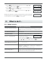
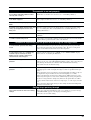
11-1 What to do if... ............................................................................................................................. 39
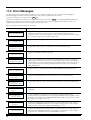
11-2 Error Messages ........................................................................................................................... 42
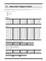
12 Instruction Support Chart .................................................................................................................. 43
13 Character Sets ...................................................................................................................................... 44
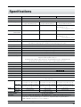
Specifications ............................................................................................................................................. 45
Windows® is a registered trademark or trademark of Microsoft® Corporation in the United States and/or other countries.
Copyright © 1998 ROLAND DG CORPORATION
1
To Ensure Safe Use
About
and
Notices
Used for instructions intended to alert the user to the risk of death or severe
injury should the unit be used improperly.
Used for instructions intended to alert the user to the risk of injury or material
damage should the unit be used improperly.
* Material damage refers to damage or other adverse effects caused with
respect to the home and all its furnishings, as well to domestic animals or
pets.
About the Symbols
The
symbol alerts the user to important instructions or warnings. The specific meaning of
the symbol is determined by the design contained within the triangle. The symbol at left means
"danger of electrocution."
The
symbol alerts the user to items that must never be carried out (are forbidden). The
specific thing that must not be done is indicated by the design contained within the circle. The
symbol at left means the unit must never be disassembled.
The
symbol alerts the user to things that must be carried out. The specific thing that must
be done is indicated by the design contained within the circle. The symbol at left means the
power-cord plug must be unplugged from the outlet.
Do not disassemble, repair, or
modify.
Doing so may lead to fire or abnormal
operation resulting in injury.
Ground the unit with the ground
wire.
Failure to do so may result in risk of
electrical shock in the even of a mechanical
problem
Use only with the power cord
included with this product.
Use with other than the inculuded power
cord may lead to fire or electrocution.
2
Do not use with any electrical power
supply that does not meet the
ratings displayed on the unit.
Use with any other power supply may lead
to fire or electrocution.
Do not use while in an abnormal
state (i.e., emitting smoke, burning
odor, unusual noise, or the like).
Doing so may result in fire or electrical
shock.
Immediately switch off the power, unplug
the power cord from the electrical outlet,
and contact your authorized Roland dealer
or service center.
Do not attempt to unplug the power
cord with wet hands.
Doing so may
result in electrical
shock.
Do not use with a damaged power
cord or plug, or with a loose electrical outlet.
Use with any other
power supply may
lead to fire or
electrocution.
When unplugging the electrical
power cord from a power outlet,
grasp the plug, not the cord.
When not in use for prolonged
periods, unplug the power cord from
the electrical outlet.
Unplugging by
pulling the cord
may damage it,
leading to fire or
electrocution.
Failure to do so may
result in danger of
shock, electrocution,
or fire due to
deterioration of the
electrical insulation.
Do not injure or modify the electrical
power cord, nor subject it to excessive bends, twists, pulls, binding, or
pinching, nor place any object of
weight on it.
Unpacking, installing, or relocating
the unit are operations which must
be carried out by two or more persons holding the unit at its bottom
surface on the left and right sides.
Doing so may
damage the electrical power cord,
leading to electrocution or fire.
Failure to do so may
result in dropping
the unit, leading
to injury.
Do not allow liquids, metal objects
or flammables inside the machine.
Do not place hands near the platen
while in operation.
Such materials
can cause fire.
Doing so may result in injury.
Do not touch the tip of the blade
with your fingers.
Install in a level and stable location.
Doing so may result in injury.
Otherwise the unit may tip over and cause
injury.
Make sure the power to the unit is
off before attempting to replace the
separating knife.
Doing so may result in injury.
3
Use care to avoid pinching the
fingers when placing the unit on the
stand.
4
Use the joining screws to secure the
unit to the stand.
Doing so may
result in injury.
Failure to do so
may result in
falling of the unit,
leading to injury.
Roll material must be placed at a
predetermined shaft position.
Release the caster locks for the
stand before attempting to move.
Failure to do so may
result in falling of the
roll, leading to injury.
Otherwise the unit may tip over and cause
injury.
About the Labels Affixed to the Unit
These labels are affixed to the body of this product.
The following figure describes the location and content of these messages.
Do not place hands near the platen
while in operation.
N'approchez pas vos mains du
plateau de travail quand le chariot
est en mouvement.
Model name
Rating label
Use a rated
power supply.
ENGAGE
セット
RELEASE
解除
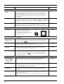
NOTICE
・Use the brake when you want to load a piece of material.
・When performing material feed or cutting, be sure to release
the brake.
・Attempting to perform material feed or cutting without
releasing the brake may make normal feed impossible and
cause the material to slip.
ご注意
・ブレーキはシートをセットするときに使用してください。
・シート送りやカッティングを行うときには、必ずブレーキを解除してください。
・ブレーキを解除しないでシート送りやカッティングを行うと、正常なシート送
りができなくなり、シートずれを起こすことがあります。
In addition to the
NOTICE
and
symbols, the symbols shown below are also used.
: Indicates information to prevent machine breakdown or malfunction and ensure correct use.
: Indicates a handy tip or advice regarding use.
5
- MEMO -
6
1
Checking Supplied Items
Check the following to make sure that you received all the items that were shipped along with the unit.
Blade Holder
(XD-CH2)
Power Cord: 1
Test-use
Application Tape
Material for Test Cuts
Test use Water Based
Fiber Tipped Pen
Tweezers
(for handling material)
Replacement blade
for separating knife
CAMM-1 DRIVER
for windows® 95
User’s Manual
2
Blade (ZEC-U5025)
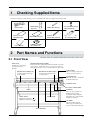
Part Names and Functions
* The figure shows the CM-500 installed with the PNS-500 special stand.
2-1 Front View
Movable Pinch Roller (middle)
This is used when cutting materials with a width of 762 mm
(30") or more. At this time, it is set at the center of the left
and right pinch rollers or above the grit roller near the center.
Front Cover
Opening the cover during
operation pauses the
machine.
Movable Pinch Roller (Right)
Set this at the right-hand edge
of the material.
Movable Pinch Roller (Left)
Set this at the left-hand edge
of the material.
Tool Carriage
The tool carriage is where the
cutter (or pen) is mounted.
Separating knife
This cuts off a piece of material
from rolled material.
Operation Panel
Pen Force Control Slider
Platen
Power Switch
ON when switched to [ ].
].
OFF when switched to [
Sheet sensor
Guide line
These are used as guides for
making sure the loaded
material is straight. Align the
right-hand edge of the material
with these scale lines.
Grit Roller
The pinch rollers and grit
rollers grip the material and
move it forward and backward.
Cutter Protector
7
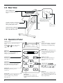
2-2 Rear View
Sheet Loading Lever
These raise and lower the pinch
rollers.
Power Connector [AC IN]
This connector accepts
standard AC power cord.
Parallel (Centronics) Connector
This is for connecting a computer
with a parallel (printer) cable.
Serial (RS-232C) Connector
This is for connecting a computer
with a serial (RS-232C) cable.
Tray
Use this to store
blades or pens.
Sheet Sensor
2-3 Operation Panel
Blinking Cursor
Used to select the desired item from the
menu.
and
keys to select items,
Use the
and
keys to change
and the
values.
1 CUT 50cm/s
0.250mm 50gf
ENTER Key
Press to enter into a subroutine of the
item selected using the cursor keys or
to confirm (save) the value set in
configuration.
MENU Key
Employed to select among the available
menus, or to cancel the making of a
setting at a particular menu.
PAUSE LED
This lights up when the CM-500/400/
300 is paused.
SHEET CUT Key
This is use to sever an already-cut
piece of material from the rolled
material.
PAUSE Key
When pressed once, this temporarily
halts cutting in progress. Pressing this
key again releases the paused state.
CURSOR Keys
Used to move the blinking cursor. The
and
keys are also used to move
the material, and the
and
keys
are used to move the tool carriage.
Power LED
This lights up when the power is
switched on.
SETUP LED
This lights up when the SETUP key is
pressed . Cutting can be performed
when this is lit.
8
Display
Provides menu display, configuration
preferences, coordinates, as well as
error messages for troubleshooting.
SETUP Key
Pressing this to detect width of the
loaded material and enable the unit for
cutting.
TEST Key
Pressed to execute a cutting test (Use
to confirm material specifications as
well as cutting speed, blade force, and
blade compensation).
3
Setup
3-1 Setting Up and Connection
Ground the unit with the ground
wire.
Failure to do so may result in risk of
electrical shock in the even of a mechanical
problem
Install on a stable surface.
Failure to do so
may result in
falling of the unit,
leading to injury.
Do not use with any electrical power
supply that does not meet the
ratings displayed on the unit.
Use with any other power supply may lead
to fire or electrocution.
Use only with the power cord
included with this product.
Use with other than the inculuded power
cord may lead to fire or electrocution.
NOTICE
Never install this unit in any of the following situations, as it could result in damage:
Places where the installation surface is unstable or not level.
Places with excessive electrical noise.
Places with excessive humidity or dust.
Places with poor ventilation, because the CM-500/400/300 generates considerable heat during operation.
Places with excessive vibration.
Connect the cable to either the parallel or the serial port. Be sure that the power to both the computer and the
main unit is switched off when connecting the cable.
Securely connect the power cord, computer I/O cable and so on so that they will not be unplugged and cause
failure during operation. Doing so may lead to faulty operation or breakdown.
Setting Up
For an explanation of how to assemble the unit and the stand (PNS-500/400/
300), refer to the “ASSEMBLY INSTRUCTIONS” included with the stand.
When using the unit while mounted on a stand, be sure to ensure a sufficient
amount of installation space for the unit. The required installation spaces for
each model are listed below.
CM-500 : 1200 mm (47-1/4") high, 1700 mm (66-15/16") wide,
and 900 mm (35-7/16") depth
CM-400 : 1200 mm (47-1/4") high, 1500 mm (59-1/16") wide,
and 900 mm (35-7/16") depth
CM-300 : 1200 mm (47-1/4") high, 1250 mm (49-1/4") wide,
and 900 mm (35-7/16") depth
The material moves while cutting is in progress. Objects which may
obstruct material movement must not be placed within 60 cm (23-5/8")
to the front or rear of the unit.
600 mm
(23-5/8")
600 mm
(23-5/8")
9
Connection
Power
outlet
Power cord
Power connector
Parallel connector
(Centronics)
Serial connector
(RS-232C)
Parallel interface cable
(Centyonics)
Serial interface cable
(RS-232C)
*Parallel interface cable
or Serial interface cable
* Cables are available separately. One which you are sure
matches the model of computer being used should be selected.
3-2 Turning on the Power
Use the switch at the front-left surface of the unit to turn on the power.
Press the side of the
switch marked “ –”.
10
3-3 Selecting the Interface
Make sure the settings for the computer (driver) match the settings for the CM-500/400/300 interface.
The selected interface type and communication parameters are stored in memory even after the power is switched off.
To change the interface type or the communication parameters, configurations must be re-entered.
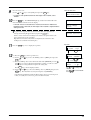
1
2
3
Close the front cover and press the MENU key.
The menu shown at right appears on the display.
Use the
and
keys to move the blinking cursor to “SUBMENU” and press
AREA
REPLOT
AXIS
SUBMENU
Use
or
to select.
Press ENTER .
ENTER key.
Press the MENU key.
CROPMARK
OVER-CUT
UPDOWN
CALIB
Press MENU .
4
Use the
and
keys to move the blinking cursor to “I/O” and press ENTER key.
VS-CMND
COMMAND
FS-CMND
I/O
Use
or
to select.
Press ENTER .
5
Select [Auto] and press the ENTER key.
INTERFACE
PARA SERI<AUTO>
* The CM-500/400/300 is equipped with an auto-interface function, and so
when left set to “AUTO,” it will automatically determine whether a parallel or
serial connection is used.
6
Next, the menu at right appears.
If connected with a serial (RS-232C) cable, make the settings to match the communication parameters for the host computer or program. (Take a look at "7 Display
Menus Flowchart.") If connected with a parallel (printer) cable, no settings are
needed here.
Use
or
to select.
Press ENTER .
PROTOCOL 1
STOP DATA PARITY
Press MENU .
* If the communication parameters for the computer and the CM-500/400/300
are not identical, the cutting data cannot be received correctly, which may
result in faulty operation.
To leave a submenu, choose [END] in the menu shown at right, and press the ENTER key.
PROTOCOL 2
BAUD HANDSHAKE
SMOOTHING
END
3-4 About the Driver
If you're using a program for Windows® 95, install the "CAMM-1 DRIVER for Windows® 95" included with the unit.
For more information about the installation and setup of the CAMM-1 DRIVER for Windows® 95, please see the Readme.txt file.
This file is found on the driver disk.
11
4
Basic Operation
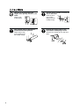
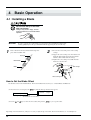
4-1 Installing a Blade
Do not touch the tip of the blade
with your fingers.
Doing so may result in injury, and the
cutting performance of the blade will be
impaired.
NOTICE
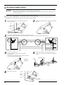
1
Be sure to support the tool mounting screw from below when installing the blade holder.
Cutting quality may become poor if installed without supporting the screw in this way.
Insert a blade into the blade holder until it snaps into
place with an audible click.
2
Push-pin
Blade holder
(1) Loosen the tool securing screw on the cutting
carriage.
(2) Support the tool-securing screw from below and
install the blade holder. Insert the blade holder
until the collar is flush with the carriage.
(3) Tighten the tool securing screw until the blade
holder is secured in place.
Blade
Tool carriage
Loosen
Tighten
Tool securing screw
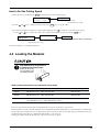
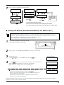
How to Set the Blade Offset
Set the blade offset for the installed blade. For more information about offset, see "9 About Blades and Material."
(1) Close the front cover and press the MENU key until the message shown below appears.
Blade compensation
1 CUT
0.250mm
50cm/s
30gf
Setting range: 0—1.000 mm
(in increments of 0.025 mm)
(2) Use the
and
keys to enter the offset value, then press the ENTER key to accept the value.
Depending on the material in use, it may be necessary to adjust the tip of the blade. For more information, see "4-5 Cutting Test."
12
How to Set the Cutting Speed
(1) Close the front cover and press the MENU key until the message shown below appears.
1 CUT
0.250mm
(2) Use the
and
Cutting Speed
50cm/s
30gf
Setting range: 1—85 cm/s.
(in increments of 1 cm/s.)
keys to change the value, then press the ENTER key to accept the value.
(3) To adjust speed during tool-up time or to adjust cutting quality, press the
Use the
and
key until the screen shown below appears.
keys to change the value (or the selection) and enablethe setting by pressing the ENTER key.
Adjust Speed During
Tool-up Time
UP50cm/s
NORMAL
Cut Quality
Setting range: NORMAL/HEAVY/HI-SPEED
Setting range: 1—85 cm/s.
(in increments of 1 cm/s.)
For more information, see "8 Display Menu Lists."
4-2 Loading the Material
Roll material must be placed at a
predetermined shaft position.
Failure to do so may
result in falling of the
roll, leading to injury.
Width (horizontal dimension) and maximum cutting width
Acceptable material widths
Maximum cutting area
CM-500
Min.90 mm (3-1/2")
Max.1372 mm (54")
1195 mm (47")
CM-400
Min.90 mm (3-1/2")
Max.1178 mm (46")
1000 mm (39")
CM-300
Min.50 mm (2")
Max.915 mm (36")
( 50—540 mm (2"—21" ) , 582—915 mm (23"—36" ) )
737 mm (29")
There is no special restriction on length (vertical dimension), as long as it is 200 mm (7-1/4") or more.
This means that you can use either flat materials such as standard-size materials (ANSI, ISO, etc.) and cut materials, or roll materials.
The grit rollers (pinch rollers that secure the material) vary from one model to another, and settable ranges are determined for the left
and right movable pinch rollers. See "Material Loading Position" on the next page.
Setting a pinch roller outside the allowed range causes an error message to appear.
13
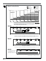
Material Loading Position
:Grit Roller
: Movable Pinch
Roller (Middle)
:Movable Pinch
Roller (Left)
: Movable Pinch
Roller (Right)
6" (approx.152 mm
12" (approx.305 mm)
Material
18" (approx.457 mm)
24" (approx.610 mm)
30" (approx.762 mm)
36" (approx.914 mm)
48" (approx.1219 mm)
54" (approx.1372 mm)
The right-hand movable pinch roller can be moved within this range.
When loading material with a width other than one indicated above,
move the right-hand movable pinch roller.
CM-500
Material with
a width
of 48" and 54"
Material with
a width of 36"
Material with
a width of 30"
Material with
a width of 24"
Material with Material with
a width of 18" a width of 12"
Material with
a width of 6"
(1*)
(2*)
* Make sure the pinch rollers are positioned above the grit rollers.
54" (approx.1372 mm)
(1*) Position of the pinch roller (middle) when using material with a width of 30" or 36"
(2*) Position of the pinch roller (middle) when using material with a width of 48" or 54"
CM-400
Material with
a width
of 36" and 46"
Material with
a width of 30"
Material with
a width of 24"
Material with Material with
a width of 18" a width of 12"
Material with
a width of 6"
(1*)
* Make sure the pinch rollers are positioned above the grit rollers.
46" (approx.1178 mm)
(1*) Position of the pinch roller (middle) when using material with a width of 30" or more.
CM-300
* Acceptable material widths
50—540 mm (2"—21" ) ,
582—915 mm (23"—36" )
Material with
a width
of 24" and 30" and 36"
Material with
a width of 18"
Material with
a width of 12"
Material with
a width of 6"
* Make sure the pinch rollers are positioned above the grit rollers.
36" (approx.915 mm)
* The CM-300 has no middle pinch roller.
14
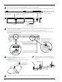
To cut off a piece of material with the separating knife, load the media within the range shown below.
Loading media outside this range may make it impossible to cut off the material with the separating knife.
13 mm (1/2") from the edge
of the leftmost grit roller
37 mm (1-7/16") from the edge
of the Rightmost grit roller
Separable range
Loading Roll Material
* When performing lengthy cutting of 1.5 m (60") or more, please refer to the section " To
Perform Lengthy Cutting" that follows this one.
For information on how to install the sheet hanger, shaft, brake, and stoppers, please refer to the assembly manual for the PNS-500/
400/300 (the stand for the CM-500/400/300).
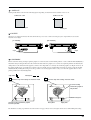
1
Mount the shaft at the location on the sheet hanger shown in the figure to match the outer diameter of
the rolled material.
When using a thick roll of
material
Shafts
When only a small amount
of material remains (material diameter is 72 mm (2-7/
8") or less)...
Shafts
2
Place the rolled material on the shaft.
3
Lower the sheet loading levers and raise the pinch rollers.
Pass the end of the material between the pinch rollers and
the grit rollers so that it extends from the front of the unit.
No good
Shafts
Sheet hanger
Stopper
Stopper
Sheet hanger
Shafts
15
4
Position so that the left-hand edge of the material lies over any one of the grit rollers.
Move the material from side to side and position so that the right-hand edge of the material lies over the rightmost grit roller.
With the material set in place,
make sure the grit rollers are
positioned correctly.
Grit roller
Sensor
Grit roller
5
Load the material so
that it lies over the
sensor on the platen.
Load the material so that it lies straight and is aligned with the guide-line marks, then move the left and right pinch rollers so
that at they are above the grit rollers.
Position the middle pinch roller over the grit roller that lies between the left- and right-hand pinch rollers.
If a pinch roller does not move easily, it may help to grasp the corresponding sheet loading lever at the back of the unit and
move it together with the pinch roller.
Position the pinch rollers over
the material, near the edges.
Pinch roller (right)
Rear View
Material
Sheet loading lever
Guide-line marks
Material
6
Lift the sheet loading lever.
The pinch rollers are lowered and the material is
secured in place.
When using a material which is narrower than 762 mm
(30"), do not lower the pinch rollers.
7
Position the stoppers so that they lightly touch the
edges of the roll, and secure in place by tightening the
screws.
Roll material
Lift the sheet
loading levers
Screws
8
16
Follow steps 1 through 7 to secure the media in place, then pull out the required length for cutting from the roller.
9
Close the front cover
Close the front cover.
Use the
and
keys to select [Roll], then press the ENTER key.
* If cutting is to be performed from the front edge of the material, select
"EDGE."
10
Press the
key. The SETUP LED lights up, and the horizontal width of the
material is detected and shown on the display.
* If "EDGE" has been selected for the material, then after the width of the
loaded material is detected, the front edge of the material is aligned with the
cutting-start area.
If a pinch roller is positioned over an area where there is no grit roller, the
message shown at right appears when you press the
key.
If this occurs, lower the sheet loading levers and move the pinch rollers to the
proper positions above the grit rollers.
Reposition the material to match this new alignment, then lower the sheet
loading levers to hold the material in place.
11
Press the MENU key once to display the top menu.
SELECT SHEET
ROLL EDGE PIECE
PRESS SETUP KEY
WIDTH LENGTH
28920
---
Change Pinch
Roller Position
Top menu
1 CUT
0.250mm
50cm/s
30gf
Press MENU once.
12
(1) Press the MENU key on the top menu once.
(2) Use the
and
ENTER key.
key to move the blinking cursor to [AREA], then press the
(3) Move the blinking cursor to the numerical value under [LENGTH]. Use the
and
keys to set the required material length for cutting. Set this to a value
that's about 0.1 m longer than the length of the cutting data.
Press ENTER key to fix the displayed values.
(4) Use the
and
AREA
REPLOT
keys to move the blinking cursor to [MOVE], then press the
ENTER key. The material is fed out by the length set for [LENGTH].
AXIS
SUBMENU
Use
or
to select.
Press ENTER .
AREA
MOVE
LENGTH
< 5.0m>
Use
or
to change the
value.
Use
or
to select “MOVE.”
Press ENTER .
If the material is misaligned and looks like it might come loose from the pinch
rollers, or actually does come loose, please reload the material.
17
To Perform Lengthy Cutting
NOTICE
When performing material feed or cutting, be sure to release the brake.
Attempting to perform material feed or cutting with the brake engaged may make normal feed impossible and
cause the material to slip.
Have on hand a piece of material that's at least 50 mm (2") wider than the cutting width.
The chance of the material slipping loose from the pinch rollers can be reduced by braking the shaft and loading the pulled-out
material while it's in a tensioned state. Follow the steps below to load the material.
1
Place the rolled material on the shaft and engage the
brake for the shaft.
2
Pull out the material from the roll and pass it through
the unit.
Brake
(It should be fixed at inner
plane of sheet hanger.)
3
Position the left- and right-hand pinch rollers as shown in the figure.
Position the middle pinch roller over the grit roller that lies between the left- and right-hand pinch rollers.
25 mm
(1")
or more
25 mm
(1")
or more
Guide lines
4
Lift the sheet loading lever.
The pinch rollers are lowered and the material is
secured in place.
When using a material which is narrower than 762 mm
(30"), do not lower the pinch rollers.
5
Position the stoppers so that they lightly touch the
edges of the roll, and secure in place by tightening the
screws.
Roll material
Lift the sheet
loading levers
Screws
6
Release the shaft brake.
Brake
18
7
Use the control panel to make the following setting.
SELECT SHEET
ROLL EDGE PIECE
Press or to
select [ROLL].
Press
.
PRESS SETUP KEY
Press
WIDTH
14612
.
LENGTH
------
Press
.
1 CUT
0.250mm
50cm/s
30gf
Press
AREA
REPLOT
AREA
MOVE
Press
Press
.
AXIS
SUBMENU
LENGTH
< 1.0m>
AREA
MOVE
or
or
to select the value.
to change the value.
LENGTH
< 2.0m>
Press or to
select [AREA].
Press or to
select [MOVE].
Press
Press
.
Set this to the
length of the
material to be
cut.
.
The set length of material is fed out.
Make sure that the material remains held by the pinch rollers.
If the material does come loose from the pinch rollers, set it in place again.
Loading Flat Material (Standard-size Material, Cut Material, Etc.)
• If the material tends to reroll in the direction of its top surface (the cutting surface), roll the material in the other
direction so that its backing paper is bent inward. If you perform cutting without changing the direction of the crease,
the material may rise up during cutting and become caught on the front cover.
• If the material strikes the shaft during cutting, remove the shaft.
1
Lower the sheet loading levers and pass the material
between the pinch rollers and the grit rollers.
Pass the material
2
Follow steps 4, 5, and 6 of " Loading Roll Material" to load a piece of material.
3
Close the front cover.
4
Use the
and
keys to select [PIECE], then press the ENTER key.
Press the
key. The tool carriage will move from side to side and the material
will move forward and backward to detect the size of the material.
When sensing ends, the display shows the loaded material size.
If a pinch roller is positioned over an area where there is no grit roller, the
key.
message shown at right appears when you press the
If this occurs, lower the sheet loading levers and move the pinch rollers to the
proper positions above the grit rollers.
Reposition the material to match this new alignment, then lower the sheet
loading levers to hold the material in place.
Close the front cover
SELECT SHEET
ROLL EDGE PIECE
PRESS SETUP KEY
WIDTH LENGTH
28920
150
Change Pinch
Roller Position
When detecting the material size in step 4, if the material is misaligned and looks like it might come loose from the pinch rollers, or
actually does come loose, please reload the material.
19
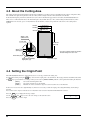
4-3 About the Cutting Area
The cutting area along the horizontal plane (the direction in which the tool carriage moves) is determined by the position of the pinch rollers.
The workable area spans the length between the two rollers, minus a margin of about 1 mm (about 0.04") on both sides.
If the material length is greater than 1,600 mm (62-15/16") when a flat material (paper) has been loaded, the CM-500/400/300 determines it to be a rolled material and sets the material length to 24,998 mm (984-1/8"). Also, when loading flat material (that is, when
[PIECE] has been selected), a piece of material that is about 100 mm (3-15/16") longer than the vertical size of the cutting data is
required.
CM-500
1195 mm (47")
CM-400
1000 mm (39")
CM-300
737 mm (29")
About 1 mm
(about 0.04")
10 mm (3/8")
24998 mm
(984-1/8")
About 15 mm
(about 9/16")
* The pairs of allows indicate the positive
direction along the X and Y axis.
Pinch roller (left)
Initial cutting coordinate
origin point (0,0)
Pinch roller (right)
4-4 Setting the Origin Point
The CM-500/400/300 allows the origin point (0,0) to be set at any position in the cutting area.
key causes the first origin point to be determined. The origin point that's determined first when
Loading material and pressing the
the
key is pressed differs according to what you selected for [SELECT SHEET] with the control panel when loading the material.
[ ROLL ]
[ EDGE ]
[ PIECE ]
Set near the left-hand pinch roller
Set at the lower-left area of the material
Material size is detected and the origin is set at the lower-left area of the material
If there is no need to move the origin initially set, then it is not necessary to make the origin point setting immediately after loading a
material.
You can also set the origin to an uncut area of a material in order to use the material with maximum effectiveness.
Press the MENU key to display the message at right.
Use the
,
,
and
keys to move the tool carriage to the desired location.
Press the ENTER key to set the origin.
20
ORIGIN SET->ENTER
0
0
4-5 Cutting Test
(How to Adjust Pen Force and Blade Extension)
Before carrying out actual cutting, you may wish to perform a "cutting test" to check whether the unit produces the cutout satisfactorily.
This is done by examining the results of the cutting test, and adjusting the blade force and the amount of blade extension. The cutting test
should be repeated until the appropriate cutting conditions for the material in use are discovered.
Cutting Test
1
Install a blade and load a material, then close the front
cover.
2
Press the MENU key until the screen shown at below
appears.
ORIGIN SET->ENTER
O
0
3
Use the
, ,
and
keys to move the tool
carriage to the place where the cutting test is to be
performed.
4
Press the
key for 0.5 seconds or more. Cutting
test starts.
The resulting cutouts will then appear as illustrated.
• Note that an area of approximately 2 square
centimeters (a little less than a square inch) is
required to make a test cutout (given that the tip of
the cutter after it has moved is at the origin at lowerleft).
Origin
(Position of the tool
installed in step 3)
Check the state of the cutting speed and the blade force.
(1) Peel off the round section
(marked by
).
When it can be peeled by itself, without
disturbing the square (marked by
the cutter force is set appropriately.
),
(2) Remove the square section
(marked by
).
The optimum blade pressure is correct if you
can clearly make out the lines left by the blade.
A
B
C
(3) The remaining cross-shaped area is used to check whether the offset
value is set correctly.
When the offset value has been correctly set, the corners of the figure
should appear cleanly cut as shown in A of the figure below.
If the offset value is too small, the corners will appear slightly
rounded as illustrated by B; an offset value which is too large will
result in a cut figure similar to C.
21
If the results of steps 1 and 2 show that the cutting quality is not acceptable, refer to "Adjusting the Blade Force" to adjust the blade
force.
If adjusting the blade force doesn't improve the cutting quality, refer to "Adjusting the Blade Extension" to adjust the blade extension.
After adjusting the blade extension, carry out a cutting test and adjust the blade force.
If the results of step 3 show that the blade offset isn't appropriate, refer to "4-1 Installing a Blade - How to Set the Blade Offset" and
adjust the blade offset.
Adjusting the Pen Force
Set the Pen Force slider at the center (default) position.
Press the MENU key to display the message at below.
1 CUT
0.250mm
50cm/s
30gf
Pen force
Setting range: 20—350 gf (in increments of 10 gf)
• Use the
and
• Then use the
keys to move the blinking cursor to the item to be set.
and
keys to change the numerical value, and press the ENTER key to enable the setting.
After using the control panel to set the pen force, if you want to raise or lower the blade force slightly according to the blade length, you
can use the Pen Force slider to make fine adjustments in the pen force.
Move the slider to the right or left to gradually raise or lower the pen force and set it at an appropriate value.
The range of fine adjustment for pen force using the Pen Force slider is within 30 gf up or down from the value set with the control
panel.
When using the control panel to set the pen force, move the Pen Force slider to its center (default) position.
Pen Force
DOWN
UP
-2 -1 0 +1 +2
PEN FORCE
Adjusting the Blade Extension
The amount of cutter blade extension can be adjusted by rotating the cap. If it is necessary to adjust the amount of blade extension,
remove the blade holder, adjust the amount of blade extension as shown in the figure below, then remount the blade holder on the cutting
carriage.
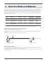
When using the included material or a general type of equivalent material, the unit should generally be used with the
cap tightened at its highest position (maximum blade extension = 2.5 mm (0.0984")). When cutting material having
base paper that is thin with respect to the material (material thickness), or material having no base paper, the amount
of blade extension should be adjusted so that the blade does not cut through the base paper.
Each indicator tick corresponds to 0.1 mm,
and adjustment for 0.5 mm can be made by
rotating the cap one full turn
[Adjusting the amount of blade extension]
Perform a cutting test and gradually extend the blade. Take care to
ensure that the amount of blade extension does not exceed the
thickness of the material portion plus the thickness of the base
paper.
Thickness of
Thickness of
Amount of
the base paper
cutter blade = the material +
portion
extension
2
If the blade leaves a faint mark on the base paper, the amount of
blade extension is optimal.
22
Incorrect cutting conditions may cause symptoms such as those described below.
Blade force
• The sheet is easily torn.
• The cutter requires frequency replacement.
• Cutting extends through the base paper, and normal advancing
of the sheet becomes impossible.
• The unit suffers damage.
Blade offset
Corners flare outward,
with "horns."
Too large
Too large
Too small
Corners are rounded.
Too small
Some parts of the sheet remain uncut.
For Materials with a Strong Adhesive Layer
If you are using a material with a strong adhesive layer, the adhesive layer may adhere to itself immediately when cut. This means that even
though the material has actually been cut, it may appear as if it has not been cut, and blade force may mistakenly be set too high.
If a cutting test shows that the material peels easily and the blade traces on the carrier paper are optimal, then the material is being cut.
Take care not to set the blade force excessively high.
23
4-6 Downloading Cutting Data
The unit will begin cutting when it receives cutting data sent from computer.
Software Setting
Make the settings described below to match the program that you're using.
If you're outputting the data from a Windows-based program, select either [CM-500], [CM-400], or [CM-300] as the printer.
If you're outputting the data from an MS-DOS-based program, selection the CM-500/400/300 as the output device. If the CM-500/400/
300 is not an available selection, choose the PNC-1860, PNC-1410, PNC-1210, PNC-1850, or PNC-1200 (models supporting CAMMGL III).
For the interface connection, choose the type of interface you're using to connect the host computer with this product.
Select either the parallel (Centronics) or serial (RS-232C) interface. Choose the one that the host computer and the CM-500/400/300 are
connected by.
Pausing Cutting Operations
If you want to stop the CM-500/400/300 momentarily while it is performing cutting, follow the procedure described below.
Press the
key.
Cutting is paused and the screen shown at right appears on the display.
PAUSE ON
CONT. STOP VIEW
[Continue cutting]
[To Terminate Cutting]
Press the
First of all, stop the flow of data being sent by the
computer.
key.
Cutting is resumed.
Use the
and
keys to choose "STOP" and press the
ENTER key. Cutting stops and the display returns to the top
menu.
[Checking the Status of Cutting]
The tool carriage can be moved toward the control panel to allow the cutting status to be checked visually.
Use the
and
keys to choose "VIEW" and press the ENTER key. The tool carriage moves toward the control panel. To resume
cutting, follow the procedure described in "Continue cutting" above.
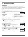
Repeating the same cutting
The "Replot" feature allows you to create numerous copies of same cutting.
(1) Press the MENU key until the screen shown at right appears, then use the
and
keys
to select "REPLOT" and press the ENTER key.
(2) Use the
and
AREA
REPLOT
ROTATE
SUBMENU
REPLOT
START
CLEAR
keys to select "START," then press the ENTER key to begin replotting.
The Replot function calls up all data in the data buffer and performs cutting with this data. When performing replotting, follow
the steps below to delete the data in the data buffer before send the data to be replotted from the computer.
(1) Press the MENU key until the screen shown at right appears, then use the
and
keys
to select "REPLOT" and press the ENTER key.
and
(2) Use the
data buffer.
24
keys to select "CLEAR" and press the ENTER key to delete the data in the
AREA
REPLOT
ROTATE
SUBMENU
REPLOT
START
CLEAR
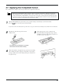
4-7 Applying the Completed Cutout
Once cutting has been completed, follow the procedure below for application instructions.
• Make sure beforehand that the surface where the work is to be stuck is clean and free of all dust or oily deposits.
• When applying the work to a transparent surface, such as a window, you can use a water-based pen (which can be
wiped off afterwards) to mark guidelines on the reverse side of the glass, to aid in getting the work aligned properly.
• If you discover after it is stuck in place that air bubbles were trapped under the work, use a needle to puncture them.
Then you can smooth out the material out so that it sticks securely.
1
With the CM-500/400/300, the portion where you've performed cutting is automatically cut off from the material.
Press the
key to cut off the portion from the material.
If you want to remove the material, then open the front cover, press down the sheet loading levers, and then remove the material.
2
Strip/Weed uses all unneeded portions from the
completed work.
3
Stick application tape over the completed work.
Press down firmly on the application tape to remove
air bubbles. If you do not press firmly enough the cut
area will not stick to the surface.
* You should have weed boarders or rectangles
drawn around work to facilitate weeding.
4
Transfer the material to the application tape, position it, and carefully
affix it, making sure that it is aligned correctly. Rub over the application tape to make sure the work is firmly stuck in place. Then peel off
the application tape.
25
4-8 When Cutting is Completed
When not in use for extended
periods, unplug the power cord from
the electrical outlet.
Failure to do so may
result in danger of
shock, electrocution,
or fire due to
deterioration of the
electrical insulation.
NOTICE
1
Do not leave the tool mounting screws tightened. Tightening the screw makes it more difficult to install the
blade holder.
Lower the sheet loading levers and remove the
material.
2
(1) Loosen the tool securing screw on the cutting
carriage.
(2) Remove the blade holder from the cutting carriage.
Cutting carriage
Tool securing screw
remove the
Material
3
Press the push-pin and remove the blade from the
blade holder.
If a blade was used, wipe the blade with a soft cloth to
remove any material that may cling to it.
Press the push-pin
Blade holder
Blade
26
4
Turn off the power.
POWER/ERROR LED
goes out
5
Maintenance
5-1 Cleaning
NOTICE
Always turn off the CM-500/400/300 before cleaning it.
Never lubricate the mechanisms.
Do not clean with solvents (such as benzine or thinners).
Cleaning the body
Use a cloth moistened with water then wrung well, and wipe gently to clean. Wipe the operation panel and display gently with a
clean, soft cloth.
Cleaning the platen
Use a cloth moistened with water then wrung well, and wipe gently to clean.
Cleaning the grit rollers
With the sheet loading levers lowered and the pinch rollers raised, use a commercially
available brush to remove dust and other detritus. Brush horizontally while rotating the
grit rollers.
If dust builds up it may prevent the paper from being held securely, and degrade plot
precision.
Cleaning the pinch rollers
Lower the sheet loading levers and raise the pinch rollers.
Use a cloth moistened with water then wrung well, and wipe gently to clean.
Cleaning the front cover
Use a cloth moistened with water then wrung well, and wipe gently to clean. If severe a neutral detergent may be used. Never
use anything other than water, or a neutral detergent.
Cleaning the blade holder cap
If material debris is adhering to the inner surface of the cap for the blade holder, loosen and remove the cap, then remove the
material debris.
27
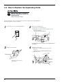
5-2 How to Replace the Separating Knife
Make sure the power to the unit is
off before attempting to replace the
separating knife.
Doing so may result in injury.
If the separating knife, replace it with the replacement blade included with the CM-500/400/300.
Follow the steps below to replace the blade.
1
Switch off the power to the CM-500/400/300.
2
Remove the separating knife.
(1) Loosen the screw until it slips out.
(2) Grasp the screw portion, and slowly pull it out in the
direction of the arrow.
* Do not pull back while doing this.
(2)
(1)
* If the blade remains in the carriage, use the included tweezers
to remove it.
3
Replace with a new knife.
4
Install the separating knife.
(1) Grasp the screw portion and slowly insert it into
the groove.
* Take care to ensure that the knife does not slip
(2) Tighten the screw.
(1)
Positioning groove
The knife is secured in place
by the magnet.
(2)
28
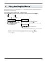
6
Using the Display Menus
This section describes the basic steps for using the display menus. Use this information together with "7 Display Menus Flowchart" on
the following page to make menu settings.
Use the and keys to move the blinking cursor (" ") and choose a setting.
Then use the and keys to change the value (or the selection) and enable the setting by pressing the ENTER key.
1 CUT
50cm/s
0.250mm 30gf
Press the MENU key to change to
the next menu
AREA
REPLOT
AXIS
SUBMENU
Select "AREA"
MENU
Use the and keys to move the
blinking cursor (" ") and choose a setting
Press the ENTER key to advance
to the next setting screen
AREA
MOVE
LENGTH
<1.0m>
Then use the and keys to change the value and
enable the setting by pressing the ENTER key
The value enclosed in angled brackets ("<>") is the current setting
ROTATE
<0deg> 90deg
Use the and keys to move the blinking cursor
(" ") and choose a setting
The selection enclosed in angled brackets ("<>") is the current setting
• To return to the menu selection screen from any of the menu value setting screens, press the MENU key.
• To return to the previous screen without changing the numerical settings, pressing the MENU key without
pressing the ENTER key.
29
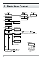
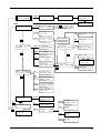
7
Display Menus Flowchart
For details about each of the menus, see the "8 Display Menu Lists."
Power on
MENU
+ Power on
+ Power on
Openning message
ENGLISH JAPANESE
GERMAN FRENCH
CM-500
Roland DG Corp.
ENGLISH/JAPANESE/
GERMAN/FRENCH/
SPANISH/ITALIAN
After loading a sheet,
close the front cover.
SELECT SHEET
ROLL EDGE PIECE
ROLL/EDGE/PIECE
or
Use
to select.
Press ENTER
DEMO CUT
or
Use
to select.
Press ENTER to enable the setting.
SPANISH ITALIAN
ENTER
SETUP
PRESS SETUP KEY
WIDTH
14612
LOADING SHEET
ROLL
LENGTH
-----MENU
TOP MENU
1— 8
1 CUT
0.250mm
0—1.000
(in increments of
0.025 mm)
AREA
REPLOT
1—85 (in increments of 1 cm/s)
NORMAL/HEAVY/ HI-SPEED
1—85
(in increments of 1 cm/s)
50cm/s
30gf
UP 50cm/s NORMAL
20—350
(in increments of 10 gf)
Align the blinking cursor at the value, press
After making the setting for [LENGTH], press
MENU
AXIS
SUBMENU
AREA
MOVE
AREA
AXIS
LENGTH
< 1.0m>
or
to change the value, then press ENTER to confirm.
or
to move the blinking cursor to [MOVE] and press ENTER .
-24.9 m—+24.9 m (in increments of 0.1 m.) to feed the sheet at the set length.
* When [FEET] is selected for [AREAUNIT] : -82.17—+82.17 (in increments of 0.33 feet)
AXIS ROTATION
<0deg> 90deg
MENU
0deg / 90deg
REPLOT
START
REPLOT
CLEAR
START/CLEAR
To the SUB MENU
Cutting Machine is
performing cutting
PROCESSING 50gf
0.250mm
50cm/s
Press PAUSE .
MENU
PAUSE ON
<CONT.>STOP VIEW
Use
,
,
, and
to move the tool
ORIGIN SET->ENTER carreage and sheet to the position on the
sheet where the origin point is to be set.
0
0
Press ENTER to enable the setting.
30
CONT: Cutting is continued (resumed)
STOP: Cutting is stopped (cutting
performed for data already
received)
VIEW: The tool carriage moves to the right side
AREA
REPLOT
AXIS
SUBMENU
CROP-MARK
BASEPOINT->ENTER
0
0
ALIGNPOINT->ENTER
0
0
CROPMARK SETTING
COMPLETED!
CROPMARK SETTING
FAILED,SET AGAIN
SUBMENU
CROPMARK UPDOWN
OVER-CUT CALIB
UPDOWN
UP/DOWN ->ENTER
MOVE
->CURSOR
OVER CUT
OVER CUT
OFF <ON>
Pressing ENTER moves the blade up or down.
Pressing , , , or
moves the cutter in
the +Y, -Y, -X, or +X directions, respectively.
STOP
OFF/ON
1/2
CALIB X CALIB Y
0.00%
0.00%
CALIB
MENU
When set to [SERIAL]
or [AUTO] (communicati
on parameter setting)
-0.19% — 0.19%
(in increments of 0.01%.)
VS-CMND
COMMAND
FS-CMND
I/O
DATA
PROTOCOL 1
STOP DATA PARITY
PARITY
FS-CMND
FS COMMAND
<IGNRORE>EFFECT
MENU
IGNORE / ACCEPT
COMMAND
BAUD
COMMAND MODE
1 2 <AUTO>
PARA (Parallel) / SERI (Serial) / AUTO
UNIT
AREAUNIT
TOOL-CHG PREFEED
PROTOCOL 2
BAUD HANDSHAKE
INTERFACE
PARA SERI<AUTO>
UNIT
MENU
BAUD RATE
19200 <9600>
BAUD RATE
4800 2400
1 (mode 1) / 2 (mode 2) / AUTO
I/O
PARITY MODE
<NONE>ODD EVEN
NONE / EVEN / ODD
IGNORE / ACCEPT
MENU
DATA BIT
7 <8>
7/8
VS COMMAND
<IGNRORE>EFFECT
VS-CMND
STOP BIT
<1> 2
2400 / 4800 / 9600 / 19200
HANDSHAKE
HANDSHAKE
<H-WIRE>XON/OFF
H-WIRE (Hardwire) / XON/OFF
DISPLAY UNIT
<MACHINE> MILI
MACHINE / MILI (Milimeter)
AREA
UNIT
MENU
AREA MENU UNIT
<METRE> FEET
METRE / FEET
PEN-CHG
TOOL-CHG COMMAND
<IGNORE> EFFECT
IGNORE / ACCEPT
PREFEED
AUTO PREFEED
<OFF> ON
OFF / ON
TESTPTRN
SHEET CUT
DEMO
TESTPTRN
TYPE1 / TYPE2
MENU
MENU
DEMO CUT
SMOOTHING
TESTPTRN
<TYPE1> TYPE2
END
AUTOCUT
DEMO CUT
START->ENTER
IGNORE / EFFECT
SPEED
Select [END.]
Press ENTER .
SMOOTHING
SMOOTHING
<OFF> ON
SHEET CUT
AUTOCUT
MARGIN
COMMAND
<IGNORE> EFFECT
SPEED
PASSES
SPEED
50 cm
40—85 (in increments of 1 cm/s)
MARGIN
OFF / ON
MARGIN
30 mm
5—50 (in increments of 5 mm)
PASSES
PASSES
<1> 2
1/2
31
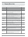
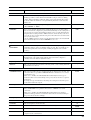
8
Display Menu Lists
This chart lists the menus of the CM-500/400/300 grouped by usage. Menus indicated by an Circle ("
section at the end of the chart. Please refer to these additional explanations when using such menus.
MENU
") are explained further in the
Explanation
Default
Determining the type of sheet loaded
SELECT SHEET
This selects the type of material to be used ("ROLL," "EDGE," or "PIECE").
-
Setting cutting conditions
1—8
It is possible to set the cutting parameters (plotting parameters) to match the tool
and material (pen and paper condition), and store them for later use. Five items can
be stored: cutting speed , blade compensation, blade force, tool movement speed
during tool-up, and CUT QUALITY. These settings can be stored in memory as
eight patterns (numbered 1 through 8).
** cm/s
This sets the speed blade for during cutting. Perform a cutting test and set the
conditions to match the loaded material and the installed cutter.
50 cm/sec.
*.**mm
This sets the amount of offset for the blade during cutting. Perform a cutting test
and set the conditions to match the loaded material and the installed cutter. When
using the included test material and blade or equivalent parts, cutting can be
performed using the factory-default settings.
0.250 mm
**gf
This sets the force for the blade during cutting. Perform a cutting test and set the
conditions to match the loaded material and the installed cutter.
50 gf
SMOOTHING
If you want the curves of circles and arcs to be cut smoothly, set this to “ON.”
When on, however, small text or intricate designs may also be cut with rounded
corners. If this happens, change the setting to “OFF” and perform cutting again.
ON
NORMAL
(CUT QUALITY)
This sets the cutting quality. Ordinarily this is left set to "NORMAL." When rapid
cutting is desired, such as when cutting a large material, set this to "HI-SPEED."
When load is large, or if the material is not cut smoothly, or when small text is to
be cut attractively, set this to "HEAVY."
UP
This sets the speed of movement when the tool is raised and moves to the next
position for cutting during a cutting operation.
1
OVER CUT
This cuts an excess margin of 1 mm (1/16") from the first and last line segments.
This selection is normally left set to "OFF," and is set to "ON" when cutting
especially attractive corners is desired. When cutting small text or intricate
graphics, however, this should be set to "OFF" to avoid cutting into the material.
-
NORMAL
50 cm/s
OFF
Setting the origin point
ORIGIN SET
Set a user origin at an arbitrary point on the material.
After the material has been loaded, be sure to set the origin to the bottom left of the
material.
-
Rotating the origin point
2
AXIS ROTATION
32
This rotates the cutting coordinate origin by 90 degrees. This is normally set to
“0deg,” which means that the origin is at the bottom left of the material. Setting
this to “90deg” moves the origin to the bottom right of the material, thereby
rotating the cutting pattern by 90 degrees.
* Don’t forget that the coordinate axis changes when the origin is rotated.
0deg
MENU
Explanation
Default
AREA
This moves the material by the length to be cut before actual cutting is performed,
making it possible to ensure that the material will not slip or come loose during
cutting. When performing continuous cutting on the same material, this can also
be used to make sure that there is enough remaining material to cut the data that
will be sent.
1.0 m
AREA UNIT
Sets the units used to specify length in display menu “AREA”. Units may be set to
either “METRE” or “FEET”.
METRE
PREFEED
Set to on for automatic material feed at cutting. If this is set to on, when cutting
data is sent from the computer, the plotter will automatically execute cutting after a
1 m (39-3/8") feed. After the material is loaded be sure to feed the material by the
length needed for cutting with the “AREA” function. (Some data may cause feed
over 1 m (39-3/8"), such as when the next point of movement is located more than
1 m (39-3/8") to the rear.)
* If the “AREA” function is used to feed the material in advance, the material will
not be automatically fed even when “PREFEED” is set to on.
OFF
Feed the loaded material
Align the axis
3
CROPMARK
This is used when cutting materials with alignment marks (crop marks) printed
around the graphics, such as for making stickers or seals. The crop marks are set
as reference points and correction points, enabling the graphics to be cut with
accuracy.
-
Correct for the cutting distance error based on actual measurement
CALIB
This adjusts the respective distances of the X and Y axes. Compare the actual
measurements of the cutting results with the data sent from the computer to
calculate and set the distance adjustment value.c
0.00%
Repeating the same cutting - Deletes any data in the replot buffer
REPLOT
This cuts the data in the replot buffer. Selecting "Clear" causes existing data in the
replot buffer to be deleted.
-
Selecting the instruction set
COMMAND MODE
This selection enables the type of instructions that are understood by the unit. You
can set the unit to accept either CAMM-GL III mode 1 instructions (“1”) or mode
2 instructions (“2”).
When set to “AUTO,” the CM-500/400/300 automatically detects the type of
instructions first received after turning on the power, and sets itself to accept those
instructions.
To change the type of instructions, first change the setting, then switch the power
to the unit off and back on again.
AUTO
Selecting the connection interface
INTERFACE
This selects the interface for connecting a computer to the CM-500/400/300. Set
this to “PARALLEL” for a parallel connection or to “SERIAL” for a serial
connection.
When set to “AUTO,” the CM-500/400/300 automatically detects whether a
parallel or serial type interface is used when data is first received after turning on
the power, and sets itself accordingly.
AUTO
Setting the protocol for a serial connection
STOP BIT
This marker tells the system when a character data set end.
1
DATA BIT
The size (length) of one block of data.
8
PARITYMODE
Parity is used to check whether data was received correctly.
BOUD RATE
Determines the speed of data transmission.
HANDSHAKE
Sets the handshake mode for when the CM-500/400/300 is connected the host
computer via the serial interface.
NONE
9600
H-WIRE
33
MENU
Explanation
Default
TOOL-CNG COMMAND
This is normally set to "IGNORE" when performing cutting. When a toolselection instruction (SP instruction) is sent from the computer while this is set to
"EGNORE," the SP instruction is ignored and operation continues without pause.
When set to "EFFECT," SP exchange instructions are accepted and operation
pauses. If tool change is needed, open the front cover, change the tool, then press
the ENTER key.
IGNORE
VS COMMAND
To perform cutting at the speed determined by a VS command (tool speed setting
command) sent from the computer, set this to "EFFECT". When set to "IGNORE",
cutting is performed using the values for "** cm/s" and "UPSPEED" set at the top
menu.
IGNORE
FS COMMAND
To perform cutting at the tool force determined by an FS command (tool force
setting command) sent from the computer, set this to "EFFECT." When set to
"IGNORE," cutting is performed using the values for "** gf" set at the top menu.
IGNORE
Giving priority to settings from the computer
This chooses a cutting-test pattern.
TESTPTRN
This performs an ordinary cutting test
with [Type 1]. For thin materials or cases
where graphics are too small to obtain
good cutting results with [Type 1], make
the setting for [Type 2].
TYPE1
TYPE2
TYPE1
This sets the material cutoff conditions.
AUTO CUT
(Material cutoff)
To enable AUTO CUT (material cutoff) using a command, set this to [Enable].
Regardless of whether the setting is at [Enable] or [Disable], the material can be
cut off by pressing the
IGNORE
key.
SPEED
This sets the AUTO CUT (material cutoff) speed.
Set this to a suitable speed for the loaded material and installed blade.
50 cm/s
MARGIN
This sets the amount of margin from the cut edge of the material for the next
starting point for cutting after cutting off the material.
30 mm
PASSES
This sets the number of times material cutoff is performed (once for [1] or twice
for [2]). When working with thicker material or other material that's difficult to
cut, set this to [2]. Pressing the
number of times set here.
1
key once performs material cutoff the
Other setting
ENGLISH, JAPANESE, GERMAN,
FRENCH, SPANISH, ITALIAN
The CM-500/400/300 is capable of displaying all its menus in either of six
languages, English, French, German, Spanish, Italian and Japanese.
UNIT
This sets the type of unit for coordinate values that appear on the display. Set this
to “MECHANICAL UNIT” for display in cutting coordinate units (1 = 0.025 mm),
or to “MILLIMETER” for display in millimeters.
DEMO CUT
This performs an operation check when the CM-500/400/300 is not working
correctly.
-
UP/DOWN MOVE
This moves the tool up or down. It also moves the tip of the blade in any of four
directions (-X, +X, -Y, or +Y).
With the tool down, the tool carriage can be moved with the four cursor keys to cut
the sheet.
-
34
ENGLISH
MILLIMETER
1 OVER CUT
Cutting results differ as shown in the following figures depending on whether the Overcut function is on or off.
OVER CUT: ON
OVER CUT: OFF
Cutting line
Cutting line
2 ROTATE
Whenever you employ the Rotate function (which allows you to rotate a character 90 degrees), the origin will be located at the
material’s lower-right.
[90° Rotation]
[0° Rotation]
Y
Origin
X
X
Origin
Y
3 CROPMARK
This is used when cutting around pre-printed graphics on a material, such as when making stickers or seals. With the CM-500/400/300, a
material is always loaded parallel to the unit. This means that unless the graphics to be cut have been printed parallel to the material, the
cutting lines become shifted from the graphics, and it becomes impossible to accurately cut around the graphics (see Figure A below). If
the printed graphics have crop marks, the positions of the crop marks can be stored in memory and used as reference points by the CM500/400/300. By making this setting, it becomes possible to cut around graphics with accuracy even when the graphics have not been
printed parallel to the material (Figure B).
Crop mark:
A
Cutting line:
When the crop mark setting has not been made
Material
B
When the crop mark settings has been made
Material
Accurate cutting
around the graphic is
not possible
Within 5 degrees
Accurate cutting around the graphic
becomes possible
Base point
Align point
The methods for setting crop marks are described on the next page. Please refer to the figures shown above while making this setting.
35
Do not place hands near the platen
while in operation.
Doing so may result in injury.
• The crop mark setting cannot be made if the angle of the base point and the align point is more than 5 degrees.
• Crop marks cannot be set when the "ROTATE" display menu is set to "90 deg."
Load the material (with pre-printed graphics) and install the water based fiber tipped pen included with the CM-500/400/300. The
alignment tool is installed in the same way as the blade holder.
(1)
(1) Press the MENU key until the screen shown at right appears, then use the
select "SUBMENU" and press the ENTER key.
and
keys to
(2) When the screen shown at right appears, press the ENTER key to change to menu for setting
the base point.
(3) Use the
, , , and
keys to move to the tool carriage to a position below and to the
left of the crop mark printed on the material. Line up the water based fiber tipped pen with
the center of the crop mark. After the alignment tool has been positioned correctly, press the
ENTER key. The display then advances to the menu for setting the align point.
(4) Use the
, , , and
keys to move to the tool carriage to the crop mark printed at the
lower right of the material. Line up the water based fiber tipped pen with the center of the
crop mark. After the alignment tool has been positioned correctly, press the ENTER key.
(5) When the crop mark setting has been made successfully, the display shows screen (A), then
returns to the screen shown in step (2). Replace the alignment tool with a blade. If the crop
mark setting could not be made, the display shows screen (B) before returning to the screen
shown in step (2). If this happens, reload the material and make the setting again.
AREA
REPLOT
AXIS
SUBMENU
(2)
CROPMARK
OVER-CUT
UPDOWN
CALIB
(3)
BASEPOINT->ENTER
0
0
(4)
ALIGNPOINT->ENTER
0
0
(A)
CROPMARK SETTING
COMPLETED !
(B)
CROPMARK SETTING
FAILED,SET AGAIN
36
9
About the Blades and Materials
This section indicates the proper cutting conditions for various types of materials, as well as blade lifespans. Cutting conditions and
blade life vary according to the hardness of the material and the usage environment. Making the settings for the conditions described
below does not automatically guarantee attractive cutting results in all situations. Before performing actual cutting, be sure to carry
out a cutting test and make any necessary adjustments (see "4-5 Cutting Test"). If the material is not cut through completely even
when the tool force is increased by 50 to 60 gf more than the tool force values shown below, it means that the useful life of the blade
has ended. Replace with a new blade.
Blade
Material
Tool-force
Speed
Amount of cutter
blade extension
Life of a blade
(General guide)
ZEC-U1005
General Signage Vinyl
50 — 150 gf
85 cm/sec.
0.25 mm (0.01")
8000 m
ZEC-U5025
General Signage Vinyl
Fluorescent Vinyl
Reflective Vinyl
30 — 100 gf
120 — 200 gf
100 — 200 gf
85 cm/sec.
85 cm/sec.
85 cm/sec.
0.25 mm (0.01")
0.25 mm (0.01")
0.25 mm (0.01")
4000 m
4000 m
4000 m
ZEC-U1715
Rubber material for
sandblasting stencil
100 — 200 gf
20 cm/sec.
0.25 mm (0.01")
Varies according
to material type
*
The values for lifespan are intended to serve as a general guide when cutting materials of identical type.
Rubber materials for sandblasting stencils which can be cut:
A) Materials with a material thickness of 1 mm (0.04") or less
B) Materials with only carrier paper on both flanks of the material (Position the left and right pinch rollers above the strips of carrier
paper.)
C) Materials with carrier paper which is hard enough to withstand material feed
Carrier paper
Material
A) 1 mm (0.04") or less
B) 15 mm (9/16") or more
B) 15 mm (9/16") or more
About the Separating Knife:
It may not be possible to sever some thicker materials (such as rubber sandblasting templates) or thin, flimsy materials. In such cases,
use a commercially available cutter knife or scissors to cut off the material.
Material with a strong tendency to reroll (that is, with a warp in the direction of the cutting surface) may catch on the carriage or the front
cover after being cut off.
37
10
NOTICE
Plotting on Paper Media
Do not use coated paper. The coating may flake or peel off and adhere to the grit rollers, making it impossible
to perform cutting (or plotting) correctly.
Before cutting, plotting using pen and paper can ensure that your design is correct without wasting materials.
This feature can also be used to plot template designs on thick materials that may not be able to be cut.
* Since the design of the CM-500/400/300 differs inherently from that of dedicated plotters, it does not accommodate
functions such as high-speed plotting, automatic pen changes, pen dry protection, or the like.
Acceptable pens and paper media
Acceptable paper
Acceptable paper widths
Acceptable pens
CM-500
High-quality paper
Min.90 mm (3-1/2") Max.1372 mm (54")
Water-based fiber-tipped pens
Thick water-based fiber-tipped pens
CM-400
High-quality paper
Min.90 mm (3-1/2") Max.1178 mm (46")
Water-based fiber-tipped pens
Thick water-based fiber-tipped pens
CM-300
High-quality paper
Min.50 mm (2") Max. 915 mm (36")
( 50—540 mm (2"—21" ) , 582—915 mm
(23"—36" ) )
Water-based fiber-tipped pens
Thick water-based fiber-tipped pens
Menu Settings for Plotting
To perform plotting on a material of paper or the like, first use the display menus to make the settings described below.
If attractive plotting is impossible, adjust the setting parameters within the ranges shown below.
1. Tool No. (see "8 Display Menu Lists/Setting cutting conditions/1—8" )
When "Blade offset" is set to "0.000 mm," the tool number shown on the upper line of the display changes from "CUT" to "PEN."
Select the tool number to be set and make the settings for conditions 2 through 5. Please note that if a tool number for which cutting
conditions have previously been set is selected, the earlier conditions are deleted.
2. Pen Speed (see "8 Display Menu Lists/Setting cutting conditions/ ** cm/s" )
Water based fiber tipped pen / Thick water based fiber tipped pen: 10—50 cm/sec
Set a low Pen Speed value to ensure clear plots with no faintness.
3. Pen Force (see "4-5 Cutting Test (How to Adjust Blade Force/Adjusting the Cutter Blade)" )
Water based fiber tipped pen
Thick water based fiber tipped pen
: 30—60 gf
: 40—120 gf
4. Blade offset (see "4-1 Installing a Blade/How to Set the Blade Offset")
Set this to "0.00 mm."
5. Cut quality (see "8 Display Menu Lists/Setting cutting conditions/NORMAL (CUT QUALITY)" )
Set this to "Normal."
6. Setting for pen change instructions
If CAD software for plotting use has been used to output data (in RD-GL I format), pen-change instructions are sent to the CM-500/
400/300. If the pen is to be changed during plotting, use "1. Tool number" to set the tool numbers to be used to match the pen
numbers set with the software. Because tool changes are not necessary when cutting is performed, the CM-500/400/300 is ordinarily
set not to accept pen-change instructions. This setting makes it possible to enable the CM-500/400/300 to accept and execute penchange instructions.
38
(1) Press the MENU key until the screen shown at right appears, then use the
and
keys
to select "SUBMENU" and press the ENTER key.
(2) Press the ENTER key, then press the MENU key twice the screen shown at right appears.
Then use the
and
keys to select "TOOL-CHG" .
(3) Press the ENTER key to display the screen shown at right, then use the
select "EFFECT" and press the ENTER key.
and
keys to
Depending on the setting made for "6. Setting for pen change instructions," operation is paused when
a tool-change instruction is received while plotting is in progress. To change the tool, open the front
cover and exchange the tool. Then press the ENTER key to resume cutting.
11
AREA
REPLOT
AXIS
SUBMENU
UNIT
AREAUNIT
TOOL-CHG PREFEED
TOOL-CHG COMMAND
IGNORE <EFFECT>
TOOL-CHG:TOOLNO2
What to do if...
11-1 What to do if...
CM-500/400/300 troubleshooting
Is the power cord connected correctly?
Connect the power cord included with the CM-500/400/300 to the unit, and plug
the other end securely into an electrical outlet (see “3-1 Setting Up and Connection”).
Is the CM-500/400/300 power on ?
Turn on the power.
Is the front cover closed?
Close the front cover when performing cutting (see “4-2 Loading the Material” ).
Is the CM-500/400/300 in the temporary
halt state ? Is operation paused?
If the screen shown at rights is displayed,
it means that operation is paused.
To resume cutting, press the
PAUSE ON
CONT. STOP VIEW
key again.
To abort cutting, first stop the flow of cutting instructions from the computer. And
use the
and
keys to select "STOP," then press the ENTER key.
If connected via the serial port, do the
communication parameters for the CM-500/
400/300 match those of the computer ?
At the display menus, make the correct settings for the communication parameters
(see “3-3 Selecting the Interface” ).
Is the computer set up correctly ?
Check the following items:
• DIP switches
• Memory switches • Interface board
parameters • Other settings
Read the computer user’s manual and set it up correctly.
Are the computer and the CM-500/400/300
linked with the right cable ?
• Communication
The type of cable you need is determined by your computer and the software you
are using. Even if the computer is the same, running different software may require
a different cable. Use the cable specified in your software.
39
Are the computer and the CM-500/400/300
connected correctly?
Correctly connect the computer and the CM-500/400/300 (see “3-1 Setting Up and
Connections” ).
Is the interface setting correct?
At the display menu, make the correct setting for the interface connecting the
computer and the CM-500/400/300 (see “3-3 Selecting the Interface” ).
Is the OS set up correctly ?
Check the following items:
• Output port selection • Output device selection • Output port open
• Communication Parameters • Other settings
Check the OS’s user’s manual and set it up correctly.
Are the application software settings
correctly ?
Check the following items:
• Output device specifications (select a device name that matches the instruction
system.
If the wrong device is selected an incorrect instruction may be output, resulting
in an error).
• Communication Parameters • Other settings
Check the software user’s manual and set it up correctly.
A message appears on the display
Change Pinch
Roller Position
CLOSE COVER
Sheet Set Error
Set Sheet Again
The location of one or more of the pinch rollers is not correct.
If this happens, lower the material loading levers and move the pinch rollers to
the proper positions above the grit rollers. Reposition the material to match this
new alignment, then lower the material loading levers to hold the material in
place.
This is displayed when the front cover is opened during cutting. Cutting operation
is halted, and the message is displayed on the screen.
Cutting restarts when the cover is closed.
This is displayed when the material has been loaded at a position where the sheet
sensor does not function.
Follow the steps under "4-2 Loading the Material" to load the material so that it is
positioned above the sheet sensor.
This is displayed when the material is removed after pressing the
Load a material and press any key to cancel the error message.
Motor Error
Power ON Again
40
key.
Shows motor error status.
This is displayed when the CM-500/400/300 is heavily loaded, such as during a
media jam, when heavy stock is cut across a long distance without initial material
feed, or when the material is abruptly pulled from the roll during cutting.
In this case, turn the power off and back on again (if a media jam has occurred,
clear the jam before turning the power back on).
For large cutting data with a roll material, use the “AREA” function on the
display menu to feed the roll material by the length of the cut (ensure a small
margin by setting a length that is about 0.1 m longer than the cutting data).
When using a thick material, change the display menu setting from "NORMAL"
to "HEAVY."(see “8 Display Menu Lists” /"NORMAL" (CUT QUALITY) .
If the above message is displayed even after"NORMAL" (CUT QUALITY) is set
to “HEAVY,” turn the power off and then back on again, and reduce the “**cm/s”
value in the display menu. See “8 Display Menu Lists” / ** cm/s .
The material is not cut properly
Are the blade and blade holder installed
correctly and securely ?
Install these so that there is no looseness (see “4-1 Installing a Blade” ).
Is the blade chipped ?
If it is, replace it with a new one (see “4-1 Installing a Blade” ).
Check if there are any dirty deposits on the
blade.
If dirty, remove and clear the blade.
Are blade speed, blade compensation, and
cutting speed appropriate for the sheet
being cut?
Perform a cutting test and use the display menu to select the appropriate values
(see “4-5 Cutting Test (How to Adjust Blade Force and Blade Extencion)” / “8
Display Menu Lists” ).
Is a thick material being used?
When using a thick material, change the display menu setting from "NORMAL" to
"HEAVY."
Is a wide material being used?
When using a material with a width greater than 762 mm (30"), lower the middle
pinch roller at a position near the center of the material.
The Material slips away from the pinch rollers during the cutting process
Is a material with sprocket holes being
used?
If a material with holes for sprocket feed is being used, placing the pinch roller
above the hole portion may cause the material to slip. Be sure to set the pinch
roller over the material to the inner side of the hole portion.
If a flat material (such as a standard-size
material or piece material) has been
loaded, has the “PIECE” setting been
selected for the material type?
When loading the material, select “PIECE” for the “SELECT SHEET” display
menu (refer to “4-2 Loading the Material”).
Is the material being cut blocked at some
position?
Make sure that the left and right edges of the material do not touch the inner
surfaces, front cover of the CM-500/400/300 during cutting. Such contact may not
only damage the material, but could also make normal material advancing
impossible and cause the material to slip.
Is the material being cut blocked at some
position?
If the front edge of the material you are working with is at an angle, cut off the
odd-shaped part to make it straight, then align it so that it is parallel with the grit
roller.
If the material is fed for a long distance, the material will be less likely to slip out
of alignment if the pinch rollers are moved inward slightly (5 to 25 mm).
When a roll material is loaded, use the display menu “AREA” function to feed a
material by the length to be used (ensure a small margin by setting a length that is
about 0.1 m longer than the cutting data), make sure the pinch rollers are still in
contact with the material (not off the left or right edges, or on the edges), and then
cut.
If the material is pulled while cutting it is more likely that material misalignment
and motor errors will occur.
Cutting stops partway through
Does material strike the front cover during
cutting?
If the edge of the material strikes the front cover, causing it to open, the message
"CLOSE COVER" appears on the display and cutting pauses.
Close the cover to resume cutting.
41
11-2 Error Messages
An error message will appear if incoming data has any of the errors listed in table. Since the error is shown in the display for
informational purposes, the data transfer continues and you are allowed to perform the next operation.
To get the error message to go away, press the ENTER key.
Note that even though the error message is no longer displayed after you press thee ENTER key, the CM-500/400/300 will retain in
memory the fact that the error occurred. To clear the error internally, you can give the default instruction, IN; or the error code
output instruction, OE. (The error can be cleared by turning the power off.)
The error messages and their meanings are as follows:
Error massage
Er1:Command
Not Recognized
Appears if an instruction that the CM-500/400/300 cannot interpret is sent. This error is
generated if an instruction from the “mode2” set is sent when the unit has been set to
recognize “mode1,” or viceversa. Change the setting for the recognized instruction set, using
the control panel, and this error should no longer occur.
Er2:Wrong Number
of Parameters
Appears if the number of parameters differs from the permissible number.
Er3:Out of
Parameter range
Appears if the value specified for a parameter is out of the permissible range.
Er5:Unknown
Character Set
Appears if an unusable character is specified.
Er10:Output
Request Overlap
Appears if an output instruction is sent from the computer during execution of a previous
output instruction. More precisely, there is a certain amount of delay between the moment an
output instruction is given and the instant actual output begins. This error message appears if
the new output request arrives during this delay time. (The delay time can be set using the
[ESC].M instruction.)
Er11:Command
Not Recognized
Appears if a device control instruction that the CM-500/400/300 cannot interpret is sent.
Er12:Wrong
Parameter
Appears if an invalid parameter has been specified for a device control instruction.
Er13:Out of
Parameter range
Appears if the value for a device control instruction parameter exceeds the permissible limit.
Er14:Termination
Error
Er15:Framing/
Parity Error
42
Meaning
Appears if the number of parameters for a device control instruction is more than that
permissible.
Appears if a framing error, parity error, or overrun error occurs at the time of data
reception.(There is a problem with one of these settings: Baud Rate, Parity, Stop Bits, or Data
Bits. The protocol settings for the CM-500/400/300 must be made correctly in order to match
the settings your computer is set to use.)
Er16:Buffer
Overflow
Appears if the I/O buffer has overflowed.(There is a problem with the connecting cable, or
the settings for Handshaking. Make sure you are using a cable appropriate for the computer
being used. Also, check that the setting for Handshaking is correct.)
Er18:
Indeterminate
Appears if the I/O buffer has overflowed.(There is a problem with the connecting cable, or
the settings for Handshaking. Make sure you are using a cable appropriate for the computer
being used. Also, check that the setting for Handshaking is correct.)
12
Instruction Support Chart
A "CAMM-GL III Programmer's Manual" is available for separate purchase for those wishing to create their own programs for this
machine. For further information, please contact your authorized Roland dealer or service center.
The list uses marks, each of which means:
: Compatible
: Incompatible
: Ignored
mode 1
Instruction Compatibility Instruction Compatibility Instruction Compatibility Instruction Compatibility Instruction Compatibility
H
D
M
I
R
L
B
X
P
S
Q
N
C
E
A
G
K
T
^
mode 2
Instruction Compatibility Instruction Compatibility Instruction Compatibility Instruction Compatibility Instruction Compatibility
AA
AR
CA
CI
CP
CS
DF
DI
DR
DT
EA
ER
EW
FT
IM
IN
IP
IW
LB
LT
OA
OC
OE
OF
OH
OI
OO
OP
OS
OW
PA
PD
PR
PT
PU
RA
RR
SA
SC
SI
SL
SM
SR
SS
SP
TL
UC
VS
WD
WG
XT
YT
Instruction in mode 1 and mode 2
Instruction Compatibility Instruction Compatibility Instruction Compatibility Instruction Compatibility
!FS
!NR
!PG
!ST
Device control instruction
Handshake instructions
Instruction Compatibility Instruction Compatibility Instruction Compatibility Instruction Compatibility Instruction Compatibility
ESC.B
ESC.M
ESC.N
ESC.H
ESC.@
ESC.O
ESC.E
ESC.L
ESC.I
About instructions
Instruction Compatibility Instruction Compatibility Instruction Compatibility
ESC.J
ESC.K
ESC.R
43
13
Character Sets
Automatic backspace
44
Specifications
CM-500
Mechanism
Media-movement method
Driving method
Digital control servo motor
Maximum cutting area
Acceptable media widths
CM-300
CM-400
Width: 1195 mm (47")
Width: 1000 mm (39")
Width: 737 mm (29")
Length: 24998 mm (984-1/2")
Length: 24998 mm (984-1/2")
Length: 24998 mm (984-1/2")
Min. 90 mm (3-1/2") / Max. 1372 mm (54")
Min. 90 mm (3-1/2") / Max. 1178 mm (46")
Min. 50 mm (2") / Max. 915 mm (36")
(50—540 mm (2"—21") ,
582—915 mm (23"—36"))
Width of material that
0—1270 mm (0"—50")
0—1067 mm (0"—42")
Min. 90 mm (3-1/2") / Max. 1372 mm (54")
Min. 90 mm (3-1/2") / Max. 1178 mm (46")
0—812 mm (0"—32")
can be cut off
Acceptable paper widths
Min. 50 mm (2") / Max. 915 mm (36")
(50—540 mm (2"—21") ,
582—915 mm (23"—36"))
Acceptable paper types
High-quality paper
Tools
Cutters: Special cutter for CAMM-1 series
Pens: Water-based fiber-tipped pens, and Thick water-based fiber-tipped pens (options)
Max. cutting speed
During cutting: 850 mm/sec. (in all directions) During tool-up: 1202 mm/sec. (in 45° direction)
Cutting speed
10—850 mm/sec. (in increments of 10 mm/sec.)
Blade force
20—350 gf (in increments of 10 gf)
Mechanical resolution
0.0125 mm/step (*0.000492"/step)
Software resolution
0.025 mm/step (0.000984"/step)
Distance accuracy
Error of less than +/- 0.2% of distance traveled, or 0.1mm (0.00394"), whichever is greater
Repetition accuracy
0.1 mm or less (excluding stretching/contraction of the material)
Range for assured repetition accuracy (*)
For materials with a width exceeding 610 mm (24"): Length 4,000 mm (157-7/16") (CM-500/400 only)
For materials with a width of 610 mm (24") or less : Length 8,000 mm (315-15/16")
Interface
Parallel (Centronics compatible), Serial (RS-232C)
Buffer size
2 MB (1.3 MB for replot buffer)
Instruction system
CAMM-GLIII (mode1 and mode2)
Switches
Power switch, Pen force slider
Control switches
MENU, ENTER ,TEST, SETUP, PAUSE, SHEET CUT,
LED
,
,
,
POWER LED, SETUP LED, PAUSE LED
Liquid crystal display unit: 16-character by 2 lines
Display
1.0 A/117V, 0.5A/220-230V, 0.5A/230-240V
Power consumption
Acoustic noise level
Cutting mode: under 62dB (A)
Standby mode: under 40dB (A)
(According to ISO 7779)
Dimensions
Main unit
With stand
1586 mm (W) x 286 mm (D) x 281 mm (H)
1391 mm (W) x 286 mm (D) x 281 mm (H)
1128 mm (W) x 286 mm (D) x 281 mm (H)
(62-1/2" (W) x 11-5/16" (D) x 11-1/8" (H))
(54-13/16" (W) x 11-5/16" (D) x 11-1/8" (H))
(44-7/16" (W) x 11-13/16" (D) x 11-5/16" (H))
1586 mm (W) x 756 mm (D) x 1142 mm (H)
1391 mm (W) x 756 mm (D) x 1142 mm (H)
1128 mm (W) x 756 mm (D) x 1142 mm (H)
(62-1/2" (W) x 29-13/16" (D) x 44-15/16" (H)) (54-13/16" (W) x 29-13/16" (D) x 44-15/16" (H)) (44-7/16" (W) x 29-13/16" (D) x 44-15/16" (H))
Weight
Main unit
With stand
41 kg (90.4 lb.)
35 kg (77.2 lb.)
27 kg (59.5 lb.)
67.5 kg (148.8 lb.)
60 kg (132.3 lb.)
50 kg (110.2 lb.)
Operating temperature
5—40°C (41—104°F)
Operating humidity
Accessories
35—80% (non-condensing)
Power cord x 1, Blade holder (XD-CH2) x 1, Blade (ZEC-U5025) x 1, Test-use water based fiber tipped pen x 1,
Test-use sheet x 1, Test-use application tape x 1, Tweezers x 1, Replacement blade for separating knife x 1,
CAMM-1 DRIVER for windows® 95 x 1, User’s manual x 1
For items indicates by an asterisk "*", please see the next page.
45
( )
* The following conditions must be satisfied:
- Material type: 3M Scotchcal Mastercut Film, ARLON Series 2100
- Special stand (a roll material must be set at the rear and on the inner sheet hanger)
- Side margins: 25 mm (1") or more for both the left and right margins
- Front margin: 25 mm (1") or more
(After loading the material, using the display menu to select “EDGE” as the material type automatically sets a front margin of
25 mm (1").)
- Use of the display menu’s “AREA” function to perform feed of the material length plus 0.2 m and set the material correctly
- Cutting of the following data one time
Side margins: 25 mm (1") or more
Movable
pinch roller (left)
(1) The letters are cut in order starting with "R"
(2) After the last letter ("P") has been cut, the machine returns to the origin
point and the outer border is cut
Front margin: 25 mm (1") or more
Cutter
protector
Origin
Y
Side margins:
Feed length
X
25 mm (1")
Sheets with a width exceeding 610 mm (24"): 4,000 mm (157-7/16")
or more
Sheets with a width of 610 mm (24") or less : 8,000 mm (315-15/16")
Movable pinch roller (right)
The origin is rotated 90 degrees ("AXIS" on the display menu is set to "90deg").
46
Cut length
Fills the
hard clip
Interface specifications
Parallel
Standard
In compliance with the specifications of Centronics
Input signals
STROBE (1 BIT), DATA (8 BITS)
Output signals
BUSY (1 BIT), ACK (1 BIT)
Level of input/output signals
TTL level
Transmission method
Asynchronous
Serial
Standard
RS-232C specifications
Transmission method
Asynchronous, duplex data transmission
Transmission speed
2400, 4800, 9600, 19200 (Selected using panel keys.)
Parity check
Odd, Even, or None (Selected using panel keys.)
Data bits
7 or 8 bits (Selected using panel keys.)
Stop bits
1 or 2 bits (Selected using panel keys.)
Handshake
DTR or XON/XOFF (Selected using panel keys.)
Parallel connector (in compliance with
specifications of Centronics)
Signal
number
Terminal
number
Signal
number
Pin Connection
Serial connector (RS-232C)
Signal
number
Terminal
number
Signal
number
NC
36
18
HIGH**
NC
25
13
NC
HIGH*
35
17
GND
NC
24
12
NC
NC
34
16
GND
NC
23
11
NC
GND
33
15
NC
NC
22
10
NC
HIGH*
32
14
NC
NC
21
9
NC
NC
31
13
HIGH*
DTR
20
8
NC
30
12
GND
NC
19
7
SG
29
11
BUSY
NC
18
6
DSR
28
10
ACK
NC
17
5
CTS
27
9
D7
NC
16
4
RTS
15
3
RXD
14
2
TXD
1
FG
GND
26
8
D6
NC
25
7
D5
NC
24
6
D4
23
5
D3
22
4
D2
21
3
D1
20
2
D0
19
1
STROBE
Pin Connection
47
Please read this agreement carefully before opening the sealed
package or the sealed disk package
Opening the sealed package or sealed disk package implies your acceptance of the terms and conditions of this agreement.
If you do NOT accept this agreement, retain the package UNOPENED. (This product is just one of included items. Please
be aware that any amount of the purchase price will not be refunded for return of this product as a single item, regardless
of whether the package is opened or unopened.) The enclosed Roland product is a single user version.
Roland License Agreement
Roland DG Corporation ("Roland") grants you a non-assignable and non-exclusive right to use the COMPUTER
PROGRAMS in this package ("Software") under this agreement with the following terms and conditions.
1. Coming into Force
This agreement comes into force when you purchase and open the sealed package
or sealed disk package.
The effective date of this agreement is the date when you open the sealed package
or sealed disk package.
2. Property
Copyright and property of this Software, logo, name, manual and all literature
for this Software belong to Roland and its licenser.
The followings are prohibited :
(1) Unauthorized copying the Software or any of its support file, program module
or literature.
(2) Reverse engineering, disassembling, decompiling or any other attempt to
discover the source code of the Software.
3. Bounds of License
Roland does not grant you to sub-license, rent, assign or transfer the right granted
under this agreement nor the Software itself (including the accompanying items)
to any third party.
You may not provide use of the Software through time-sharing service and/or
network system to any third party who is not individually licensed to use this
Software.
You may use the Software by one person with using a single computer in which
the Software is installed.
4. Reproduction
You may make one copy of the Software only for back-up purpose. The property
of the copied Software belongs to Roland.
You may install the Software into the hard disk of a single computer.
5. Cancellation
Roland retains the right to terminate this agreement without notice immediately
when any of followings occurs :
(1) When you violate any article of this agreement.
(2) When you make any serious breach of faith regarding this agreement.
6. Limitations on Liability
Roland may change the specifications of this Software or its material without
notice.
Roland shall not be liable for any damage that may caused by the use of the
Software or by exercise of the right licensed by this agreement.
7. Governing Law
This agreement is governed by the laws of Japan, and the parties shall submit to
the exclusive jurisdiction of the Japanese Court.
R5-010125