1
OPERATOR'S MANUAL
CLEAN BURN MODELS: CB-1400, CB-1800, and CB-2800
MULTI-OIL FURNACES
with CB-525-S2 BURNER
U.L. Listed Used Oil
Burning Appliance
#MH15393 (N)
U.L.-C Listed
#CMP217
PUBLICATION DATE: 12/15/01, Rev. 7
CLEAN BURN PART # 43081
WARNING: DO NOT assemble, install, operate, or maintain this equipment without first
reading and understanding the information provided in this manual. Installation and
service must be accomplished by qualified personnel. Failure to follow all safety precautions
and procedures as stated in this manual may result in property damage, serious personal injury
or death.
IMPORTANT FOR U.S. INSTALLATIONS: All installations must be made in accordance with state and local codes
which may differ from the information provided in this manual. Save these instructions for reference.
IMPORTANT FOR CANADIAN INSTALLATIONS: These instructions have been reviewed and accepted by
Underwriters' Laboratories of Canada as being appropriate for the installation of the ULC labelled products
identified herein. The use of these instructions for the installation of products NOT bearing the ULC label and
NOT identified herein may result in an unacceptable or hazardous installation.
IMPORTANT FOR CANADIAN INSTALLATIONS: The installation of this equipment is to be accomplished by
qualified personnel and in accordance with the regulation of authorities having jurisdiction and CSA Standard B 139,
Installation Code for Oil Burning Equipment.
WARRANTY INFORMATION
Clean Burn, Inc., MANUFACTURER, hereby warrants that MANUFACTURER's products shall be free from defect in
material and workmanship under normal use according to the provisions and limitations herein set forth. MANUFACTURER
warrants the heat exchanger/combustion chamber, excluding the ceramic flame target, for three (3) years from the date of
purchase by the purchaser and pro rata thereafter according to the following schedule: (a) If the defect occurs during the
fourth year, customer pays 60% of parts, replacement or repair. (b) If the defect occurs during the fifth year, customer pays
65% of parts, replacement or repair. (c) If the defect occurs during the sixth year, customer pays 70% of parts, replacement or
repair. (d) If the defect occurs during the seventh year, customer pays 75% of parts, replacement or repair. (e) If the defect
occurs during the eighth year, customer pays 80% of parts, replacement or repair. (f) If the defect occurs during the ninth
year, customer pays 85% of parts, replacement or repair. (g) If the defect occurs during the tenth year, customer pays 90% of
parts, replacement or repair. MANUFACTURER warrants all other Clean Burn products for a period of one (1) year from the
date of purchase by the purchaser.
LIMITATIONS:
The obligation of MANUFACTURER for breach of warranty shall be limited to products manufactured by MANUFACTURER (1) that are
installed, operated and maintained according to MANUFACTURER's instructions furnished and/or available to the purchaser upon
request; (2) that are installed according to all other applicable Federal, State and local codes or regulations; and (3) that the purchaser
substantiates were defective in material and workmanship notwithstanding that they were properly installed and correctly maintained as set
forth above and were not abused or misused.
The obligation of MANUFACTURER shall be limited to replacing or repairing the defective product, at the option of the
MANUFACTURER. MANUFACTURER shall not be responsible for any labor or costs of removal or reinstallation of its products and
shall not be liable for transportation costs to and from its plant at Leola, Pennsylvania.
Use of parts for modification or repair of the product or any component part thereof not authorized or manufactured by
MANUFACTURER specifically for such product shall void this warranty.
This warranty shall not apply to any damage to or defect in any of MANUFACTURER's products that is directly or indirectly caused by (1)
force majeure, Act of God or other accident not related to an inherent product defect; or (2) abuse, misuse or neglect of such product,
including any damage caused by improper assembly, installation, adjustment, service, maintenance or faulty instruction of the purchaser.
Other than as expressly set forth hereinabove, MANUFACTURER makes no other warranty, express or implied, with respect to any of
MANUFACTURER's products, including but not limited to any warranty of merchantability or fitness for a particular purpose.
And in no event shall MANUFACTURER be responsible for any incidental or consequential damages of any nature suffered by purchaser
or any other person or entity caused in whole or in part by any defect in any of MANUFACTURER's products. Any person or entity to
whom this warranty extends and who claims breach of warranty against MANUFACTURER must bring suit thereon within one year from
the date of occurrence of such breach of warranty or be forever barred from any and all legal or other remedies for such breach of warranty.
MANUFACTURER is not responsible for and hereby disclaims any undertaking, representation or warranty made by any dealer, distributor or other person that is inconsistent with or in any way more expansive than the provisions of this limited warranty.
This warranty grants specific legal rights and shall be read in conformity with applicable state law. In some jurisdictions, the applicable
law mandates warranty provisions that provide greater legal rights than those provided for herein. In such case, this limited warranty shall
be read to include such mandated provisions; and any provision herein that is prohibited or unenforceable in any such jurisdiction shall, as
to such jurisdiction, be ineffective to the extent of such prohibition or unenforceability without invalidating the remaining provisions and
without affecting the validity or enforceability of such provision in any other jurisdiction(s).
TRADEMARKS
The Clean Burn logo is a trademark of Clean Burn, Inc. All other brand or product names mentioned are the registered
trademarks or trademarks of their respective owners.
COPYRIGHT
Copyright © 2001 Clean Burn, Inc. All rights reserved. No part of this publication may be reproduced, or distributed without
the prior written permission of Clean Burn, Inc. 34 Zimmerman Road, Leola, PA 17540. Subject to change without notice.
TABLE OF CONTENTS
SECTION 1: INTRODUCTION .................................................................................... 1-1
Guide to this Manual ........................................................................................................ 1-1
For Your Safety... ............................................................................................................. 1-2
SECTION 2: UNPACKING ......................................................................................... 2-1
Removing the Shipping Pallet .......................................................................................... 2-1
Unpacking and Inspecting All Components..................................................................... 2-1
Furnace Component List ........................................................................................... 2-1
Warranty Registration ...................................................................................................... 2-2
SECTION 3: FURNACE ASSEMBLY ......................................................................... 3-1
Understanding Assembly ................................................................................................. 3-1
Required Tools and Materials ................................................................................... 3-1
Installing the Observation Port ......................................................................................... 3-4
Determining the Fan/Blower Assembly Configuration.................................................... 3-5
Unit Heater Models: Installing the Fan Assembly ........................................................... 3-6
Installing the Fan Assembly ...................................................................................... 3-6
Installing the Fan Brace (CB-1800/CB-2800 Only) .................................................. 3-6
Central Furnace Models: Installing the Blower Assembly ............................................. 3-7
Preparing the Furnace Cabinet for Blower Installation ............................................. 3-7
Installing the Blower Mount on the Furnace Cabinet................................................ 3-9
Installing the Blower on the Blower Mount ............................................................ 3-10
Installing the Motor on the Blower ......................................................................... 3-10
Installing the Motor Pulley ...................................................................................... 3-11
Installing the Blower Pulley and V-Belt .................................................................. 3-11
Installing the Belt Guard and the Blower Guard ..................................................... 3-12
Installing the Electrical Conduit .............................................................................. 3-12
Installing the Burner ....................................................................................................... 3-13
Checking the Burner Nozzle and Electrodes ........................................................... 3-13
Mounting the Burner on the Hinge Bracket ............................................................ 3-14
Installing the Connector Block, Oil Line Tubing, and Air Line Tubing ........................ 3-14
Installing the Connector Block on the Furnace Door .............................................. 3-14
Installing the Oil Line Tubing ................................................................................. 3-15
Installing the Air Line Tubing ................................................................................. 3-16
Locking the Burner into Firing Position .................................................................. 3-16
SECTION 4: FURNACE INSTALLATION ................................................................... 4-1
Understanding Installation ............................................................................................... 4-1
Selecting a Location ......................................................................................................... 4-4
Guidelines for Selecting a Location .......................................................................... 4-4
Determining Air Flow from the Furnace ................................................................... 4-4
Mounting the Furnace ...................................................................................................... 4-5
Ceiling Mounting ...................................................................................................... 4-5
Raised Platform Mounting ........................................................................................ 4-5
Floor Mounting.......................................................................................................... 4-6
TABLE OF CONTENTS
SECTION 4: FURNACE INSTALLATION (continued)
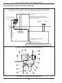
Determining the Type of Oil Tank ................................................................................... 4-7
Specifications for Inside Above Ground Tank Installation ....................................... 4-9
Specifications for Outside Above Ground Tank Installation .................................. 4-11
Specifications for Underground Tank Installation .................................................. 4-13
Installing the Oil Pump .................................................................................................. 4-14
Wiring the Furnace and Pump ................................................................................. 4-16
Wiring to the Furnace .............................................................................................. 4-16
Wiring to the Oil Pump ........................................................................................... 4-16
Installing the Oil Lines ................................................................................................... 4-17
Installing the Suction Oil Line ................................................................................ 4-17
Installing the Pressure Oil Line ............................................................................... 4-18
Installing the Compressed Air Line ............................................................................... 4-18
Installing the Stack ......................................................................................................... 4-19
Installing the Interior Stack ..................................................................................... 4-22
Installing the Barometric Damper ........................................................................... 4-22
Installing the Stack Penetration ............................................................................... 4-23
Installing the Exterior Stack .................................................................................... 4-23
Installing the Stack Cap ........................................................................................... 4-23
Installing the Wall Thermostat ....................................................................................... 4-24
Inspecting the Furnace Installation................................................................................. 4-24
SECTION 5: OIL PUMP PRIMING ............................................................................. 5-1
Understanding Oil Pump Priming .................................................................................... 5-1
Required Tools and Materials ................................................................................... 5-1
Preparing the Canister Filter for Pump Priming............................................................... 5-2
Preparing the Pump for Pump Priming ............................................................................ 5-3
Preparing the Burner for Pump Priming .......................................................................... 5-4
Activating the Pump ......................................................................................................... 5-5
Establishing the Proper Oil Flow at the Pump ................................................................. 5-6
Flushing the Oil Lines ...................................................................................................... 5-6
Adjusting the Pump Pressure ........................................................................................... 5-6
SECTION 6: STARTING AND ADJUSTING THE BURNER ...................................... 6-1
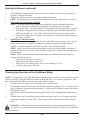
Understanding Burner Startup and Adjustment ............................................................... 6-1
Preparing the Burner for Startup ...................................................................................... 6-1
Starting the Burner ........................................................................................................... 6-3
Checking the Operation of the Fan/Blower Motor ........................................................... 6-4
SECTION 7: RESETTING THE OIL PRIMARY CONTROL ....................................... 7-1
Understanding the Oil Primary Control ........................................................................... 7-1
Using the Reset Button..................................................................................................... 7-1
TABLE OF CONTENTS
SECTION 8: ADJUSTING THE DRAFT OVER FIRE ................................................. 8-1
Checking for Correct Draft Over Fire .............................................................................. 8-1
Adjusting the Barometric Damper ................................................................................... 8-2
Solving Draft Overfire Problems ..................................................................................... 8-2
Understanding the Effect of Exhaust Fans on Draft .................................................. 8-3
Checking Draft Overfire to Determine Severity of Backdraft ................................... 8-3
Installing a Make-up Air Louver ............................................................................... 8-5
SECTION 9: MAINTENANCE ..................................................................................... 9-1
Understanding Maintenance ............................................................................................. 9-1
Annual Burner Tune-up ................................................................................................... 9-1
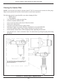
Cleaning the Canister Filter ............................................................................................. 9-2
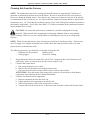
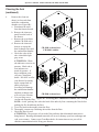
Cleaning Ash from the Furnace ....................................................................................... 9-3
Cleaning the Check Valve ................................................................................................ 9-5
Cleaning the Tank ............................................................................................................ 9-6
End of Season Maintenance ............................................................................................. 9-6
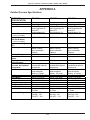
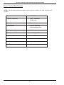
APPENDIX A
Detailed Furnace Specifications ...................................................................................... A-1
Furnace Technical Specifications ............................................................................. A-1
Burner Technical Specifications............................................................................... A-2
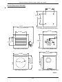
Furnace Dimensions (CB-1400) ............................................................................... A-3
Furnace Dimensions (CB-1800) ............................................................................... A-4
Furnace Dimensions (CB-2800) ............................................................................... A-5
Burner Components .................................................................................................. A-6
Oil Pump Components ........................................................................................... A-12
Fan Limit Control ................................................................................................... A-14
APPENDIX B
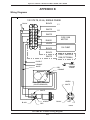
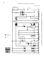
Wiring Diagrams ............................................................................................................. B-1
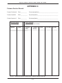
APPENDIX C
Furnace Service Record .................................................................................................. C-1
Operator's Manual: Models CB-1400, CB-1800, and CB-2800
SECTION 1: INTRODUCTION
Guide to this Manual
This manual contains all the information necessary to safely install and operate the Clean Burn Furnace
Models CB-1400, CB-1800, and CB-2800. Consult the Table of Contents for a detailed list of topics
covered. You'll find this manual's step-by-step procedures easy to follow and understand. Should
questions arise, please contact your Clean Burn dealer before starting any of the procedures in this
manual.
As you follow the directions in this manual, you'll discover that assembling and operating your new
furnace involves five basic activities as outlined here:
• UNPACKING .................................................................................................... (Section 2)
• ASSEMBLY ...................................................................................................... (Section 3)
• INSTALLATION ............................................................................................. (Section 4)
• OPERATION
• Oil Pump Priming ................................................................................. (Section 5)
• Starting and Adjusting the Burner ..................................................... (Section 6)
• Resetting the Oil Primary Control ...................................................... (Section 7)
• Adjusting the Draft ............................................................................... (Section 8)
• MAINTENANCE ............................................................................................. (Section 9)
The manual also contains important and detailed technical reference materials which are located at the
back of the manual in the Appendixes.
Please read all sections carefully--including the important safety information found in this section-before beginning any installation/operation procedures; doing so ensures your safety and the optimal
performance of your Clean Burn furnace.
1-1
Operator's Manual: Models CB-1400, CB-1800, and CB-2800
For Your Safety...
For your safety, Clean Burn documentation contains the
following types of safety statements (listed here in order
of increasing intensity):
• NOTE: A clarification of previous
information or additional pertinent
information.
• ATTENTION: A safety statement
indicating that potential equipment damage
may occur if instructions are not followed.
CAUTION: A safety statement
that reminds of safety practices or directs
attention to unsafe practices which could
result in personal injury if proper
precautions are not taken.
WARNING: A strong safety
statement indicating that a hazard exists
which can result in injury or death if proper
precautions are not taken.
DANGER! The utmost levels of
safety must be observed; an extreme hazard
exists which would result in high probability
of death or irreparable serious personal
injury if proper precautions are not taken.
In addition to observing the specific precautions listed
throughout the manual, the following general
precautions apply and must be heeded to ensure
proper, safe furnace operation.
WARNING: Never alter or modify your
furnace without prior written consent of
Clean Burn, Inc. Unauthorized
modifications or alteration can adversely
affect the proper, safe operation of your
furnace.
WARNING: The burner which is shipped
with your Clean Burn furnace is to be used
only with your furnace according to the
instructions provided in this manual. DO
NOT use the burner for any other purpose!
1-2
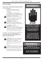
WARNING!
STOP
YOUR SAFETY IS AT STAKE!
DO NOT INSTALL, OPERATE OR
MAINTAIN THIS EQUIPMENT
WITHOUT FIRST READING
AND UNDERSTANDING THE
OPERATOR'S MANUAL!
DO NOT ADD CHLORINATED
OILS, SOLVENTS, OR PAINT
THINNERS TO YOUR USED OIL!
BURNING ANY CHLORINATED
SUBSTANCES IS ILLEGAL AND
WILL DAMAGE YOUR FURNACE!
WARNING!
THIS BURNER IS TO BE
INSTALLED ONLY ON THE PROPER,
SPECIFIED, CLEAN BURN PRODUCT
DO NOT USE THE BURNER
FOR ANY OTHER PURPOSE
Operator's Manual: Models CB-1400, CB-1800, and CB-2800
For Your Safety... (continued)
WARNING: The Best Operator is a Careful Operator! By using common sense,
observing general safety rules, and adhering to the precautions specific to the equipment, you,
the operator, can promote safe equipment operation. Failure to use common sense, observe
general safety rules, and adhere to the precautions specific to the equipment may result in
equipment damage, fire, explosion, personal injury and/or death.
WARNING: The installation, operation, and maintenance of this equipment in the U.S.
must be accomplished by qualified personnel and in compliance with the specifications in the
Clean Burn Operator's Manual and with all national, state, and local codes or authorities
having jurisdiction over environmental control, building inspection and fuel, fire and
electrical safety and the following standards of the National Fire Protection Association.
NFPA 30
Flammable and Combustible Liquids Code
NFPA 30A Automotive and Marine Service Station Code
NFPA 31
Standard for the Installation of Oil Burning Equipment
NFPA 211
Chimneys, Fireplaces, Vents and Solid Fuel Burning Appliances
NFPA88A
Parking Structures
NFPA 88B
Repair Garages
NFPA 70
National Electrical Code
The NFPA standards may be obtained from:
National Fire Protection Association (NFPA)
1 Batterymarch Park, P.O. Box 9101
Quincy, Massachusetts 02269-9101
Likewise, the installation, operation, and maintenance of this equipment in Canada is to be
accomplished by qualified personnel and in compliance with the specifications in the
Clean Burn Operator's Manual and in accordance with the regulation of authorities having
jurisdiction and CSA Standard B 139, Installation Code for Oil Burning Equipment.
Failure to comply with these standards and requirements may result in equipment
damage, fire, explosion, personal injury and/or death.
•
This furnace is listed for commercial and/or industrial use only; it is not listed for residential
use.
•
This furnace is listed with Underwriters Laboratory and Underwriters' Laboratories of
Canada to burn the following fuels:
• Used crankcase oil up to 50 SAE
• Used transmission fluid
• Used hydraulic oils
• #2 fuel oil
1-3
Operator's Manual: Models CB-1400, CB-1800, and CB-2800
For Your Safety... (continued)
WARNING: DO NOT add inappropriate or hazardous materials to your used oil, such as:
• Anti-freeze
• Carburetor cleaner
• Paint thinner
• Parts washer solvents
• Gasoline
• Oil additives
• Any other inappropriate/hazardous
material
WARNING: Burning chlorinated materials (chlorinated solvents and oils) is illegal, will
severely damage your heat exchanger, immediately void your warranty, and adversely affect
the proper, safe operation of your furnace. Instruct your personnel to never add hazardous
materials to your used oil.
DANGER! DO NOT create a fire or explosion hazard by storing or using gasoline or other
flammable or explosive liquids or vapors near your furnace.
DANGER! DO NOT operate your furnace if excess oil, oil vapor or fumes have
accumulated in or near your furnace. As with any oil burning furnace, improper installation,
operation or maintenance may result in a fire or explosion hazard.
•
If your safety decals ever become worn, lost or painted over, please call your Clean Burn
dealer for free replacements.
•
Make sure you comply with all EPA regulations concerning the use of your furnace. EPA
regulations require that:
• Your used oil is generated on-site. You may also accept used oil from
"do-it-yourself" oil changers.
• Hazardous wastes, such as chlorinated solvents, are NOT to be mixed with your
used oil.
• The flue gases are vented to the outdoors with an appropriate stack.
• Your used oil is recycled as fuel for "heat recovery". DO NOT operate your furnace
in warm weather just to burn oil.
Contact your Clean Burn dealer for current EPA regulations.
•
If your furnace ever requires service, call your Clean Burn dealer. DO NOT allow
untrained, unauthorized personnel to service your furnace. Make sure that your furnace
receives annual preventative maintenance to ensure optimal performance.
1-4
Operator's Manual: Models CB-1400, CB-1800, and CB-2800
SECTION 2: UNPACKING
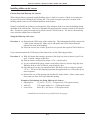
Before assembling your furnace, you must accomplish the following activities described in this section:
• Removing the Shipping Pallet
• Unpacking and Inspecting All Components
• Warranty Registration
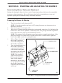
Removing the Shipping Pallet
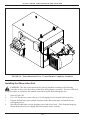
ATTENTION: Your furnace cabinet is attached to the shipping pallet with two screws to keep the
cabinet from shifting during shipment. You must remove the shipping pallet prior to assembly and
installation of the furnace. DO NOT use the pallet as a platform for furnace installation!
1.
2.
Locate the shipping screws which attach the cabinet to the pallet by looking through the round
fan opening on the side of the furnace cabinet.
Remove and discard the two screws. Carefully lift the furnace off the shipping pallet with a fork
lift, and discard the pallet.
Unpacking and Inspecting All Components
Following is an itemized list of all components you should have received in your Clean Burn furnace
shipment. Open all shipping containers and inspect all components according to the list. Immediately
notify the freight company and your Clean Burn dealer in case of shipping damage or shortage(s). Keep
all components together so you will have them as needed for furnace assembly and installation.
Furnace Component List (CB-1400, CB-1800, and CB-2800)
ONE SKID containing:
• Furnace cabinet
ONE BOX containing:
• Burner
ONE SKID containing:
• Fan assembly (Unit Heater Models) OR Blower assembly (Central Furnace Models)
• Oil pump
• Canister filter
• Vacuum gauge
• Check valve and check valve screen
• Wall thermostat
• Barometric damper
• Assorted bolts/fittings for assembly/installation of furnace components
• Operator's Manual
• Burner Oil Line and Air Line Components
NOTE: You may have received additional boxes or skids if you ordered optional accessories.
2-1
Operator's Manual: Models CB-1400, CB-1800, and CB-2800
Warranty Registration
For proper warranty registration, Clean Burn requires that you fill out the provided warranty registration
card and return it within 30 days to:
CLEAN BURN WARRANTY REGISTRATION
Clean Burn, Inc.
34 Zimmerman Road
Leola, Pennsylvania 17540
2-2
Operator's Manual: Models CB-1400, CB-1800, and CB-2800
SECTION 3: FURNACE ASSEMBLY
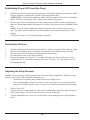
Understanding Assembly
Assembling your Clean Burn Furnace includes the following steps:
(1) Installing the Observation Port
(2) Determining the Fan/Blower Assembly Configuration
(3) Unit Heater Models: Installing the Fan Assembly
(4) Central Furnace Models: Installing the Blower Assembly
(5) Installing the Burner
(6) Installing the Connector Block, Oil Line Tubing, and Air Line Tubing
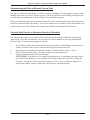
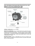
Clean Burn recommends that you review all assembly procedures before proceeding, paying careful
attention to safety information statements. Please note that some assembly procedures apply only to
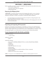
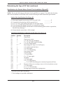
certain furnace models. Figures 3A, 3B, and 3C on the following pages provide a general overview of
the furnace components and their proper assembly and how the unit should look following proper
assembly.
Required Tools and Materials
The following tools and materials are required for furnace assembly and should be gathered before
starting any procedures:
•
•
•
9/16" open-end wrench
Medium flat-blade screwdriver
Medium adjustable wrench
3-1
Operator's Manual: Models CB-1400, CB-1800, and CB-2800
DETAIL OF HINGED
OBSERVATION PORT
JUNCTION BOX
HEX HEAD
SCREWS
BURNER CABLE
FAN LIMIT
CONTROL
HINGE
BRACKET
ELECTRICAL
JUNCTION
BOX
MOUNTING FLANGE
OBSERVATION
PORT
GASKET
SPRING
HANDLE
FURNACE THROAT
FACE
PLATE
LOCKING
RING
FRONT VIEW OF CABINET
FRONT VIEW OF CABINET WITH BURNER,
CIRCULATING FAN, CONNECTOR BLOCK, AIR LINE
AND OIL LINE INSTALLED
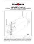
FIGURE 3A - Overview of Furnace Assembly
NOTE: Furnace shown is CB-2800.
Assembly of CB-1400 or CB-1800 is similar.
3-2
Operator's Manual: Models CB-1400, CB-1800, and CB-2800
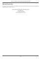
ASSEMBLED
OBSERVATION PORT
OBSERVATION PORT
HALF-MOON
PIECE
FACE
PLATE
ASSEMBLY OF
OBSERVATION PORT
FIGURE 3B - Three-dimensional View - Unit Heater Completely Assembled
3-3
Operator's Manual: Models CB-1400, CB-1800, and CB-2800
FIGURE 3C - Three-dimensional View - Central Furnace Completely Assembled
Installing the Observation Port
CAUTION: The observation port must be correctly installed according to the following
procedure to allow safe observation of the flame during furnace operation. Be sure to follow all
safety procedures as outlined in this manual when observing the flame through the port.
1.
2.
3.
4.
Refer to Figure 3B.
Use a 1/4" nut driver to remove the two (2) self-tapping screws from the half-moon piece.
Position the half-moon piece and the faceplate on the observation port, and install the two
self-tapping screws.
Open the port and make sure the faceplate moves and closes freely. If the faceplate hangs up,
loosen the hex-head screws slightly until the faceplate closes correctly.
3-4
Operator's Manual: Models CB-1400, CB-1800, and CB-2800
STOP! READ THIS NOW.
The following information is critical to the proper assembly and installation of your
Clean Burn furnace; read this section carefully before starting any other procedures.
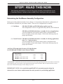
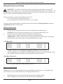
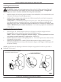
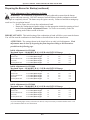
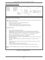
Determining the Fan/Blower Assembly Configuration
Before proceeding with the assembly of your furnace, it is important to determine the configuration of
the fan/blower assembly for your furnace model. There are two configurations to consider:
(1) Unit Heater
CB-1400, CB-1800, and CB-2800 with propeller-type fan.
This configuration is for free air application only and may NOT be ducted.
CB-1800 and CB-2800 with blower assembly for free air applications.
You must install the correct blower motor pulley as described in the
blower assembly section in this chapter. Refer to the following chart for
proper specifications.
(2) Central Furnace CB-1800 and CB-2800 with blower assembly for ducting applications
from .2 to .3 static pressure.*
You must install the correct blower motor pulley as described in the
blower assembly section in this chapter. Refer to the following chart for
proper specifications.
Air Flow (CFM) and Static Pressure (SP) Specifications
for CB-1800 and CB-2800 Central Furnace Models
Static Pressure
"H20 in Outlet
0.20*
0.30*
CB-1800 Central Furnace CFM
CB-2800 Central Furnace CFM
2300
3300
2200
3100
*ATTENTION: A qualified electrician must check the blower motor amperage during operation of the furnace to ensure that
motor amperage does not exceed 85% of the maximum amperage on the motor label. DO NOT operate the blower motor
above 85% of maximum amperage or motor damage may occur.
IMPORTANT NOTE: It is essential that qualified HVAC personnel properly design the
ductwork for your furnace and determine the static pressure for your ducting application.
3-5
Operator's Manual: Models CB-1400, CB-1800, and CB-2800
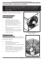
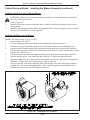
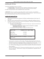
Unit Heater Models: Installing the Fan Assembly
NOTE: The following information on the installation of the fan assembly applies to Unit
Heater Models (CB-1400 or CB-1800 or CB-2800) only. If you have a Central Furnace
Model, refer to the appropriate information later in this section for installation of the
blower assembly.
CAUTION: Ducting any Unit Heater Furnace is not
permitted. See Section 4 for additional information.
Installing the Fan Assembly
(All Unit Heater Models)
1.
2.
3.
4.
5.
6.
Refer to Figure 3D.
Attach the fan assembly to the furnace
cabinet using the six hex-head bolts.
Make sure that fan blade is centered in the
round opening on the cabinet. Spin the fan
blade to check that it spins freely.
Remove the cover of the electrical junction
box.
Attach the fan motor electrical cable to the
electrical junction box.
Connect the fan motor wires according to the
wiring schematic provided in Appendix B at
the back of the manual.
FIGURE 3D - Fan Installed on
Furnace Cabinet
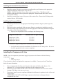
Installing the Fan Brace
(CB-1800 and CB-2800 only)
NOTE: These instructions apply to Unit Heater Models
CB-1800 and CB-2800 only. Unit Heater Model CB-1400
does not require a fan brace.
1.
2.
3.
4.
5.
Refer to Figure 3E.
Hook the fan brace end with the larger
loop over the fan guard strut.
Check that the fan brace lines up with the mounting
tab on the fan motor.
Attach the fan brace to the mounting tab using the
bolt and nut provided. Make sure the motor is
held firmly in place by the fan brace to prevent fan
vibration. DO NOT over-tension the motor.
Check that the fan blades spin freely.
FIGURE 3E - Fan Brace Installed
3-6
Operator's Manual: Models CB-1400, CB-1800, and CB-2800
Central Furnace Models: Installing the Blower Assembly
NOTE: The following information on the installation of the blower assembly applies to
Central Furnace Models (CB-1800 or CB-2800) only. If you have a Unit Heater Model
(CB-1400 or CB-1800 or CB-2800), refer to the appropriate information earlier in this
section for installation of the fan assembly.
NOTE: Ducting Central Furnace Models (CB-1800 or CB-2800) is permitted. Specifications for
ducting are provided in Section 4.
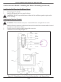
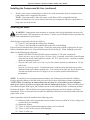
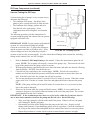
Preparing the Furnace Cabinet for Blower Installation
For Model CB-1800 Only:
1.
Refer to Figure 3F.
2.
Remove the six screws along the left edge of the cabinet so the side lip of the blower mount fits
snugly against the cabinet.
3.
To remove the bottom screw, grab the screw head with a pair of vise grips and twist it out.
For Model CB-2800 Only:
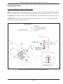
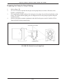
NOTE: It is important that you install the air flow plate on Model CB-2800 which ensures that the air
flow from the blower is properly channeled over the heat exchanger.
1.
Refer to Figures 3F and 3G.
2.
Slide the air flow plate through the round opening on the fan side of the furnace cabinet.
3.
Position the plate on top of the heat exchanger headers between the mounting lugs.
4.
Pull the air flow plate snugly against the inside of the sheet metal on the fan side of the furnace
cabinet.
5.
Use three self-tapping screws to mount the air flow plate in position.
NOTE: Most furnace cabinets are pre-drilled with three holes in the fan side sheet metal. If
these holes are not pre-drilled, mark the position of the lip of the air flow plate and carefully drill
three 1/8" holes to allow installation of the plate.
NOTE: Make sure the self-tapping screws are firmly tightened so that the air flow plate is held
tightly in place and cannot vibrate during blower operation.
For Ceiling-hung Furnaces Only:
1.
Refer to Figure 3F and Section 4 (Installation), Figures 4A and 4B.
2.
Install 5/8" all-thread rods in the four threaded mounting lugs on the top of the furnace cabinet.
Be sure to thread the rods into the four lugs on the furnace top until the rods are tight. Lock the
all-thread rods in place using double nuts as shown in Figure 3F.
3-7
Operator's Manual: Models CB-1400, CB-1800, and CB-2800
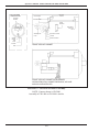
FURNACE ASSEMBLY
14
Blower Assembly Parts List
1
2
3
4
5
6
7
8
9
10
11
12
13A
13B
14
Blower Motor
Motor Pulley
Motor Mounting Plate
Motor Tensioning Bracket
Blower Pulley
V-Belt
Belt Guard
Blower
Blower Guard
Blower Mount
Top Mounting Bracket
U-Bolt
Platform Mounting: two bolts/washers
Ceiling Mounting: four all-thread rods with washers
and double locking nuts
Air Flow Plate (CB-2800 Central Furnace ONLY)
VIEW OF BLOWER ASSEMBLY
(SHOWN WITHOUT GUARDS)
REVERSED VIEW OF BLOWER ASSEMBLY
SHOWING MOTOR PULLEY, BLOWER PULLEY, & V-BELT
(SHOWN WITHOUT GUARDS)
Figure 3F - Detail of Blower Assembly and Installation of Blower on Furnace Cabinet
3-8
Operator's Manual: Models CB-1400, CB-1800, and CB-2800
Central Furnace Models: Installing the Blower Assembly (continued)
AIR FLOW
PLATE
AIR FLOW PLATE
INSTALLED ON
TOP OF HEADER
SELF-TAPPING
SCREWS
Figure 3G - Detail of Air Flow Plate Installation
Preparing the Furnace Cabinet for Blower Installation (continued)
For Platform-mounted Furnaces Only:
1.
Refer to Figure 3F.
2.
Install a washer and bolt in the two threaded lugs on the blower side of the furnace. Use the
washers and bolts which were supplied with the furnace.
Installing the Blower Mount on the Furnace Cabinet
1.
2.
3.
4.
5.
6.
7.
Refer to Figure 3F.
For Model CB-2800 Only: Make sure the air flow plate has been installed as described earlier
in the Preparing the Furnace Cabinet section.
Position the blower mount over the fan opening on the furnace cabinet.
Install the two U-bolts over the mounting lugs and through the holes in the top lip of the blower
mount.
Tighten the nuts on the U-bolts until the blower mount fits snugly aginst the side of the furnace
cabinet.
Use sets of double nuts as shown in Figure 3F, and firmly tighten the nuts to securely lock the
blower mount in position.
Attach the side lips of the blower mount to the furnace cabinet using the self-tapping screws.
3-9
Operator's Manual: Models CB-1400, CB-1800, and CB-2800
Central Furnace Models: Installing the Blower Assembly (continued)
Installing the Blower on the Blower Mount
1.
2.
3.
CAUTION: Follow the steps in this procedure carefully to ensure that the blower is installed
securely on the blower mount.
Refer to Figure 3F.
Slide the blower into position so that the blower outlet fits inside the mounting bracket on the
blower mount.
Install the top mounting bracket and firmly attach the blower using self-tapping screws as shown
in Figure 3F so the blower is safely supported.
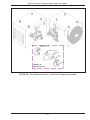
Installing the Motor on the Blower
NOTE: The blower motor is non-reversible.
1.
Refer to Figures 3F and 3H.
2.
Use the self-tapping bolts to install the motor mounting bracket on the blower.
3.
Slide the two square-head bolts upside-down in the channel of the motor mounting bracket.
4.
Install the motor mounting plate on the mounting bracket using the two bolts in the channel to
hold the plate in position. DO NOT install the nuts on the bolts yet. Make sure the plate is flush
with the side of the blower.
5.
Lift the motor into position on the motor mounting plate using the two bolts in the channel to
hold the motor in place. Now install the nuts on the two (2) bolts, and tighten the nuts.
6.
Install the additional two (2) bolts and nuts through the lower holes in the motor mounting plate
and motor. Tighten the nuts to hold the motor firmly in position.
7.
Lift up on the end of the motor mounting plate until the hole in the side of the plate is aligned
with the slot in the motor tensioning bracket. Push a bolt through the slot and install a nut to
hold the plate in position. DO NOT tighten the nut yet.
Figure 3H - Assembled View of Blower
3-10
Operator's Manual: Models CB-1400, CB-1800, and CB-2800
Central Furnace Models: Installing the Blower Assembly (continued)
Installing the Motor Pulley
CAUTION: It is essential that the correct motor pulley is installed for your specific ducting application.
Make sure that qualified HVAC personnel properly design the ductwork for your furnace and determine
the static pressure for your ducting application.
1.
Refer to Figures 3F, 3H and the following charts.
CB1800
Motor Pulley Size
CB2800
Motor Pulley Size
Free Air (Unit Heater)
3.75" O.D.
5/8" Bore
Free Air (Unit Heater)
3.55" O.D.
5/8" Bore
.2 to .3 Static Pressure (Central Furnace)
4.45" O.D.
5/8" Bore
.2 to .3 Static Pressure (Central Furnace)
3.95" O.D.
5/8" Bore
Air Flow (CFM) and Static Pressure (SP) Specifications
for CB-1800 and CB-2800 Central Furnace Models
Static Pressure
"H20 in Outlet
0.20*
0.30*
CB-1800 Central Furnace CFM
CB-2800 Central Furnace CFM
2300
3300
2200
3100
*CAUTION: A qualified electrician must check the blower motor amperage during operation of the furnace
to ensure that motor amperage does not exceed 85% of the maximum amperage on the motor label. DO NOT
operate the blower motor above 85% of maximum amperage or motor damage may occur.
2.
3.
4.
Slide the motor pulley into position on the motor shaft.
Position the key in the slot on the motor shaft.
DO NOT tighten the locking screw in the motor pulley hub until instructed to do so.
Installing the Blower Pulley and V-Belt
1.
2.
3.
4.
5.
6.
Refer to Figures 3F and 3H.
Slide the blower pulley into position on the blower shaft.
ATTENTION: Ensure that you align the motor pulley and the blower pulley with a straight
edge, or vibration and bearing damage will occur.
Tighten the locking screw in the blower pulley hub against the flat on the blower shaft. Also
tighten the locking screw in the motor pulley hub.
Install the V-belt on the motor pulley and the blower pulley.
To tension the V-belt, lift up on the end of the motor mounting plate. Firmly tighten the nut and
bolt on the tensioning bracket.
Ensure that there is a 3/4" deflection in the tensioned V-belt. DO NOT overtension the V-belt.
Repeat step #5 if necessary to achieve the proper tension on the V-belt.
3-11
Operator's Manual: Models CB-1400, CB-1800, and CB-2800
Central Furnace Models: Installing the Blower Assembly (continued)
Installing the Belt Guard and the Blower Guard
1.
2.
Refer to Figures 3F and 3H.
Install the belt guard and blower guard as shown.
CAUTION: DO NOT operate the furnace without the belt and blower guards in place on the
blower assembly.
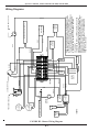
Installing the Electrical Conduit
WARNING: Ensure that the main power is turned OFF before wiring the blower motor.
1.
2.
3.
Install an electrical connector in the electrical access holes on the blower motor and the electrical
junction box on the furnace cabinet.
Feed the electrical conduit assembly through the connectors.
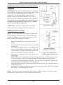
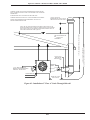
Connect the wires according to Figure 3I.
BLACK
BLACK
120 VOLTS
WHITE
L1
MAIN
POWER
MAIN
NEUTRAL
L1
WHITE
L2
L2
OIL PUMP
L2
L2
WHITE
3
3
4
4
BLUE
GREEN
GROUND
SCREW
BLACK
LINE 4
BLOWER MOTOR
LINE 1
OIL PUMP
PURPLE
RED
ORANGE
FAN LIMIT SWITCH
(COVER REMOVED)
WHITE
GREEN
WHITE
GREEN
BLACK
BLACK
RED
RED
Figure 3I - Wiring Diagram for the Electrical Junction Box on the Furnace Front
3-12
Operator's Manual: Models CB-1400, CB-1800, and CB-2800
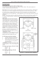
Installing the Burner
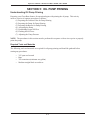
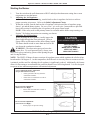
Checking the Burner Nozzle and Electrodes
NOTE: The burner nozzle is factory installed. All furnace models (CB1400, CB-1800 and CB-2800)
use a Delavan 9-5 nozzle. The nozzle size is indicated on the nozzle as shown in Figure 3J. Refer also
to Appendix A at the back of the manual for additional specifications/instructions on the burner nozzle.
ATTENTION: Check the electrode settings as specified in Figure 3J. The electrode settings must be
correct for your burner to operate properly.
BURNER NOZZLE
NOZZLE IS STAMPED EITHER 9-5
OR -5 ON FLAT OF NOZZLE HEAD
SIDE VIEW -- AA
3/16" GAP BETWEEN
ELECTRODES & NOZZLE
3X
CRITICAL DIMENSION:
NOZZLE MUST BE 1/8"
AHEAD OF THE DISK.
NOZZLE MUST NOT BE
BEHIND THE DISK.
VI
EW
B-
B
V
W
IE
A-
A
1/8"
SPARK
GAP
FRONT VIEW -- BB
Figure 3J - Burner Nozzle and Electrode Specifications
3-13
Operator's Manual: Models CB-1400, CB-1800, and CB-2800
Installing the Burner (continued)
Mounting the Burner on the Hinge Bracket
ATTENTION: Burner tube components (e.g. electrodes and retention head) are factory set. Handle the
burner with extreme care so that burner components are not damaged.
1.
Remove the nut from the bolt on the mounting flange of the furnace cabinet, and set it aside for
later use.
2.
Lift the burner into position so the burner hinge plate is mounted on the hinge bracket on the
furnace cabinet.
3.
Carefully swing the burner so the retention head enters the throat of the furnace.
4.
Check the clearance between the retention head and the furnace throat. There must be at least
1/8" clearance, so the retention head is not "bumped" as you swing the burner into firing
position.
NOTE: If the retention head "bumps" the furnace throat, adjust the hinge bracket bolts
as follows:
• While supporting the burner, slightly loosen the two (2) hinge bracket bolts.
• Carefully re-position the burner so it swings freely into its firing position.
• With the burner in its firing position, re-tighten the hinge bracket bolts.
Installing the Connector Block, Oil Line Tubing, and Air Line Tubing
Installing the Connector Block on the Furnace Door
For Model CB-1400 Only:
1.
Refer to Figure 3K.
2.
Install the mounting bracket on the furnace cabinet
using the two (2) bolts supplied.
3.
Install the connector block on the mounting bracket
using the two (2) carriage bolts supplied.
4.
Remove and discard the red caps and plugs from the
fittings and ports on the connector block. DO NOT
allow any dirt/debris to enter these components
during furnace assembly.
For Models CB-1800 and CB-2800:
1.
Refer to Figure 3L.
2.
Use the two (2) bolts to install the aluminum
connector block onto the furnace cabinet.
3.
Remove and discard the red caps and plugs from the
fittings and ports on the connector block. DO NOT
allow any dirt/debris to enter these components
during furnace assembly.
SWIVEL ASSEMBLY
MOUNTING BRACKET
CONNECTOR BLOCK
DETAIL OF MOUNTING BRACKET AND
CONNECTOR BLOCK ON CB-1400
MOUNTING
BRACKET
CONNECTOR
BLOCK
DETAIL OF OIL LINE, AIR LINE INSTALLED
ON CB-1400
Figure 3K - Installation of Connector
Block (CB-1400 only)
3-14
Operator's Manual: Models CB-1400, CB-1800, and CB-2800
Installing the Connector Block on the Furnace Door
(continued)
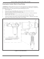
ATTENTION: The connector block includes an accumulator.
The accumulator functions like a shock absorber on the oil line
to prevent pressure buildup and protect vital burner
components. It is important that the connector block is
installed as shown so that the accumulator is in a vertical
position to prevent sediment from settling in the accumulator.
Never operate your furnace without the connector block and
accumulator properly installed on the furnace, or damage
may occur to vital burner components.
OIL LINE
OIL FITTING
ON BURNER
CB-525 BURNER
SWIVEL ASSEMBLY
CONNECTOR BLOCK
INSTALLED ON
FURNACE
FRONT VIEW OF FURNACE
ATTENTION: DO NOT use teflon tape on any fittings.
Teflon tape residues will plug vital burner components.
Installing the Oil Line Tubing
OIL LINE FITTING
ON BURNER LINED
UP WITH OIL LINE
NOTE: DO NOT disassemble the compression fitting from
the swivel fitting. To prevent leaks, the NPT threads of the
compression fitting have been sealed with hydraulic sealant
during assembly of the fittings at the factory.
1.
2.
3.
4.
5.
6.
OIL LINE
SWIVEL
ASSEMBLY
Remove and discard the red caps from the oil line
CONNECTOR
tubing.
BLOCK
Loosely install the oil line tubing into the oil line fitting
on the burner.
Use a wrench to slightly rotate the oil line fitting on the
SIDE VIEW OF FURNACE
burner counterclockwise so the tubing lines up with the
SHOWING OIL LINE INSTALLED
swivel assembly. Slightly bend the tubing as shown in
Figure 3L, if required, to "line up" the oil line.
Figure 3L - Installation of
If necessary, use a tubing cutter to cut the tubing to the
Connector Block and Oil Line
proper length.
ATTENTION: Due to adjustment of the burner hinge bracket, the oil line tubing may need to
be cut to fit properly. DO NOT lift up on the burner when installing the oil line tubing to
compensate for oil line tubing that is too long. This will place the weight of the burner on the
swivel fitting and result in leaks at the swivel fitting seal.
Make sure that the curl in the oil line is positioned as shown in Figure 3L so that the burner can
swing open correctly.
Install the oil line tubing and tighten the nuts on the compression fittings. DO NOT overtighten
these fittings to avoid damaging the ferrules.
NOTE: You may also check the positioning of the oil line according to Figure 3M on the next page
which provides a larger front view of the connector block assembly.
3-15
Operator's Manual: Models CB-1400, CB-1800, and CB-2800
Installing the Connector Block, Oil Line Tubing,
and Air Line Tubing (continued)
AIR LINE FITTING
ON BURNER
OIL LINE FITTING
ON BURNER
AIR LINE
OIL LINE
COMPRESSION
FITTING
CONNECTOR BLOCK
INSTALLED ON
FURNACE CABINET
SWIVEL
FITTING
Figure 3M - Installation of Connector Block, Oil Line and Air Line (Front View)
Installing the Air Line Tubing
1.
2.
3.
Remove and discard the red caps from the air line tubing.
Refer to Figure 3M. Push the air line tubing into the swivel fitting on the connector block until
the tubing bottoms out in the fitting.
Repeat this procedure to connect the air line tubing to the air line fitting on the side of the burner.
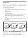
Locking the Burner into Firing Position
1.
2.
3.
4.
Swing the burner into firing position.
Install and tighten the lock-down nut on the mounting
plate bolt to secure the burner in its firing position.
Plug the burner electrical cable into the receptacle on the
top of the burner housing.
Tighten the locking ring to secure the electrical cable.
NOTE: Be sure to properly align the plug when plugging it into
the receptacle. See Fig 3N.
PLUG ON CAM
LOCK CABLE
SLOT IN PLUG
MUST ALIGN WITH
SLOT IN
RECEPTACLE
RECEPTACLE ON
TOP OF BURNER
Figure 3N - Detail of Burner
Electric Receptacle
3-16
Operator's Manual: Models CB-1400, CB-1800, and CB-2800
NOTE: Your furnace is now assembled and ready for installation. Install the furnace
as soon as possible so the burner and/or fan are not "bumped" or damaged. If you must
store the furnace for a period of time before installation, make sure it is located in a safe,
secure area.
3-17
Operator's Manual: Models CB-1400, CB-1800, and CB-2800
3-18
Operator's Manual: Models CB-1400, CB-1800, and CB-2800
SECTION 4: FURNACE INSTALLATION
Understanding Installation
Installing your Clean Burn furnace is a multi-step process which includes:
(1) Selecting a Location
(2) Mounting the Furnace
(3) Determining the Type of Oil Tank
(4) Installing the Oil Pump
(5) Wiring the Furnace and Pump
(6) Installing the Oil Lines
(7) Installing the Compressed Air Line
(8) Installing the Stack
(9) Installing the Wall Thermostat
(10) Inspecting the Installation
Clean Burn recommends that you review all procedures before beginning installation, paying careful
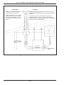
attention to safety information statements. Figures 4A and 4B provide a general overview of typical
furnace installations and should be reviewed closely before proceeding.
WARNING: The installation, operation, and maintenance of this equipment in the U.S.
must be accomplished by qualified personnel and in compliance with the specifications in the
Clean Burn Operator's Manual and with all national, state, and local codes or authorities having
jurisdiction over environmental control, building inspection and fuel, fire and electrical safety and the
following standards of the National Fire Protection Association.
NFPA 30
Flammable and Combustible Liquids Code
NFPA 30A Automotive and Marine Service Station Code
NFPA 31
Standard for the Installation of Oil Burning Equipment
NFPA 211
Chimneys, Fireplaces, Vents and Solid Fuel Burning Appliances
NFPA88A
Parking Structures
NFPA 88B
Repair Garages
NFPA 70
National Electrical Code
The NFPA standards may be obtained from:
National Fire Protection Association (NFPA)
1 Batterymarch Park, P.O. Box 9101
Quincy, Massachusetts 02269-9101
Likewise, the installation, operation, and maintenance of this equipment in Canada is to be accomplished
by qualified personnel and in compliance with the specifications in the Clean Burn Operator's Manual
and in accordance with the regulation of authorities having jurisdiction and CSA Standard B 139,
Installation Code for Oil Burning Equipment.
Failure to comply with these standards and requirements may result in equipment damage, fire,
explosion, personal injury and/or death.
WARNING: Improper installation can adversely affect the proper, safe operation of your
furnace. It is critical that your furnace installer reads and follows the instructions provided in
this manual.
4-1
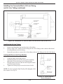
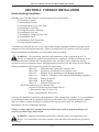
Operator's Manual: Models CB-1400, CB-1800, and CB-2800
NON-RESTRICTIVE
"CLASS A" STACK CAP
"CLASS A" STACK INSULATED STACK
WITH A STAINLESS STEEL LINER
WARNING! OUTSIDE STACK AND
STACK PENETRATIONS THROUGH
CEILING, ROOF, OR SIDEWALL MUST
BE "CLASS A" FOR FIRE SAFETY AND
TO MAINTAIN PROPER DRAFT.
WARNING! MAKE SURE TO INSTALL
ALL STACK COMPONENTS WITH
PROPER CLEARANCE FROM
COMBUSTIBLES.
EXTERIOR SINGLE WALL STACK
DOES NOT MEET CODE. EXTERIOR
SINGLE WALL STACK CHILLS THE
EXHAUST GASES RESULTING IN
POOR BURNER PERFORMANCE AND
BACK PRESSURE IN THE FURNACE.
WARNING! MAKE SURE TO INSTALL
THE PROPER ROOF SUPPORT
SYSTEM TO SAFELY SUPPORT THE
STACK.
CEILING MOUNTING SYSTEM
WATERTIGHT ROOF FLASHING:
CLEAN BURN RECOMMENDS "DEKTITE"
FLASHING FOR A WATERTIGHT SEAL
WARNING! USE MINIMUM 2-1/2" x 2-1/2"
ANGLE IRON BEAMS, BRIDGED ACROSS
SUFFICIENT STRUCTURAL MEMBERS TO
SAFELY SUPPORT FURNACE.
DOUBLE NUTS
"CLASS A" KIT FOR
INSTALLING
"CLASS A" STACK
THROUGH
CEILING
(4) "ALL THREAD" SUPPORT RODS
5/8" (1.6 CM) DIAMETER FOR ALL MODELS
WARNING! MAKE SURE TO USE DOUBLE
NUTS TO SECURELY FASTEN SUPPORT
RODS.
SINGLE WALL
STACK
DOUBLE NUTS
COMPRESSED AIR LINE
INSTALLED TO ALUMINUM
CONNECTOR BLOCK
OIL FLOW
INSTALL 2" X 2" X 4"
ELECTRICAL BOX ON
OIL PUMP MOTOR
24 VOLT WALL
THERMOSTAT
SUCTION OIL LINE
FLARE FITTING
CANISTER FILTER IN SUCTION LINE
VENT PIPE WITH
VENT CAP
CB-525
BURNER
CB-2800 FURNACE
1/4" HOLE FOR
SETTING DRAFT AT
BREACH
FLARE
FITTING
DOUBLE TAP BUSHING
REMOVABLE
STANDPIPE
CAUTION: SUCTION OIL LINE
MUST BE 100% AIRTIGHT. AIR
LEAKS CAUSE THE BURNER TO
PERIODICALLY SHUT DOWN ON
SAFETY LOCK-OUT.
SEE TANK/PUMP
INSTALLATION DIAGRAM TO
PROPERLY INSTALL THE
SUCTION OIL LINE AND PUMP
CHECK VALVE-INSTALL WITH ARROW UP
CHECK VALVE SCREEN
CLEAN-OUT
OIL STORAGE TANK
Figure 4A - Typical Furnace Installation
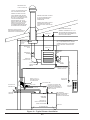
4-2
ELECTRIC
SERVICE
DEDICATED ELECTRIC CIRCUIT
ELBOW OR
CLEAN-OUT TEE
PRESSURE OIL LINE
FILL PIPE WITH
RAINTIGHT CAP
ELECTRICAL
JUNCTION
BOX
"2 WIRE" THERMOSTAT CABLE
OIL PUMP ELECTRICAL CIRCUIT
LOUVER SIDE
BAROMETRIC
DAMPER
10 FT. VERTICAL STACK HEIGHT OR
EQUIVALENT DRAFT SYSTEM TO MAINTAIN
-.02 W.C. DRAFT OVER FIRE.
Operator's Manual: Models CB-1400, CB-1800, and CB-2800
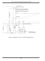
NOTE: THE LAST STACK SECTION SHALL EXTEND AT LEAST 2 FT. ABOVE THE HIGHEST
POINT AT WHICH IT COMES IN CONTACT WITH THE ROOF, AND AT LEAST 2 FT. HIGHER
THAN ANY RIDGE, PARAPET WALL OR ROOF STRUCTURE WITHIN 10 FT. OF IT.
CIRCULATING FAN SIDE
CB-2800 FURNACE
OIL PRESSURE LINE SPECIFICATIONS:
LINE LENGTH
MIN. LINE SIZE
LENGTH UP TO 50 FT.
1/2" O.D. COPPER TUBING
LENGTH UP TO 100 FT.
5/8" O.D. COPPER TUBING
LENGTH UP TO 200 FT.
3/4" O.D. COPPER TUBING
DIAMETER OF COPPER TUBING MUST BE MAINTAINED FOR FULL
LINE LENGTH.
HORIZONTAL SUCTION LINE OR
NOT TO EXCEED 10" HG OF VACUUM
CAUTION: KEEP THE SUCTION LINE AS
SHORT AS POSSIBLE.
ELECTRIC
SERVICE
NOTE: LOCAL CODES MAY
REQUIRE ELECTRICAL
SHUT-OFFS AT OR NEAR
THE FURNACE AND PUMP.
VERTICAL SUCTION LIFT
OR NOT TO EXCEED 10" HG
OF VACUUM
100% AIRTIGHT SUCTION OIL LINE
CLEAN-OUT
STANDPIPE SPECIFICATIONS:
USE MIN. 1/2" I.D. STEEL PIPE OR
MIN. 5/8" O.D. COPPER TUBING
FOR INSIDE TANK.
FOR OUTSIDE/UNDERGROUND
TANK USE MIN. 3/4"
MIN. 12" FROM CHECK
VALVE TO TANK BOTTOM.
Figure 4B - Typical Furnace Installation - Detailed
4-3
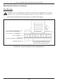
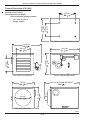
WARNING! YOUR LOCAL CODES MAY REQUIRE THAT YOUR FURNACE IS MOUNTED A MIN.
OF 8 FT. OFF THE GROUND IF THERE IS THE POSSIBILITY OF GASOLINE FUMES OR
OTHER COMBUSTIBLE OR EXPLOSIVE FUMES IN YOUR SHOP. REFER TO NFPA-88B.
DRAFT READING PORT
DRAFT AT BREACH: -.04 W.C.
DRAFT OVER FIRE: -.02 W.C.
COMPRESSED AIR LINE
24 VOLT WALL
THERMOSTAT
OIL PUMP ELECTRICAL CIRCUIT
18"
24"
36"
24"
60"
24"
18"
WARNING! MAKE SURE YOUR FURNACE
IS MOUNTED AT LEAST 5 FT. AWAY FROM
YOUR OIL STORAGE TANK. CHECK YOUR
LOCAL FIRE CODE.
"2 WIRE" THERMOSTAT CABLE
DEDICATED ELECTRIC CIRCUIT
TOP
FRONT (BURNER SIDE)
REAR (STACK SIDE)
BOTTOM
LOUVER END
BLOWER END
CHIMNEY CONNECTOR
CB1400/1800/2800 REQUIRE MIN. 8 INCH
STACK COMPONENTS. DO NOT REDUCE
STACK SIZE.
MIN. CLEARANCES TO COMBUSTIBLES AND
MIN. SERVICE CLEARANCES:
Operator's Manual: Models CB-1400, CB-1800, and CB-2800
Selecting a Location
Guidelines for Selecting a Location
The location you select for your furnace must allow the following:
• Unobstructed, even heat distribution.
• Safe, easy access for servicing.
• Unobstructed passage for shop vehicles and equipment.
• Proper clearances from combustibles. Verify according to your local safety codes.
• Adequate combustion air per local codes.
• Proper stack installation.
Adhere to the following minimum clearances from combustible surfaces and to provide adequate clearance for servicing:
• TOP ......................................................... 18"
• FRONT (burner side) .............................. 24"
• REAR (stack side) .................................. 36"
• LOUVER END ....................................... 60"
• BLOWER/FAN END ............................. 24"
• BOTTOM ............................................... 24"
• CHIMNEY CONNECTOR .................... 18"
WARNING: Your local codes may require that your furnace is mounted a minimum of eight (8)
feet off the ground if there is the possibility of gasoline fumes or other combustible or explosive
fumes in your shop area. Refer to NFPA-88B.
Determining Air Flow From the Furnace
One important consideration in selecting the proper location for your furnace is heat distribution, i.e.
how the air (heat) will circulate from your furnace. Depending on the type of furnace you ordered (Unit
Heater or Central Furnace), you will use one of two air flow configurations:
•
"Free air" circulation : this method is the easiest and most economical. In this case,
industrial-size ceiling fans may be installed to aid in efficient, even heat distribution.
NOTE: If the peak of your shop roof/ceiling is 14 feet or higher, Clean Burn recommends
the use of industrial-size ceiling fans to gently redistribute the heat from the furnace. A
minimum of one Clean Burn 56" Blade Industrial Ceiling Fan (C.B. part# 70003) or
equivalent is recommended for each 2000 square feet of heated shop space.
•
Ductwork (central furnace ONLY ): this method is more complex and requires careful
planning and additional investment for proper installation. If you plan to duct your furnace,
it is essential that qualified HVAC personnel design and install the ductwork system
according to the specifications provided in this section.
4-4
Operator's Manual: Models CB-1400, CB-1800, and CB-2800
Determining Air Flow From the Furnace (continued)
Air Flow (CFM) and Static Pressure (SP) Specifications
for CB-1800 and CB-2800 Central Furnace Models
Static Pressure
"H20 in Outlet
0.20*
0.30*
CB-1800 Central Furnace CFM
CB-2800 Central Furnace CFM
2300
3300
2200
3100
*ATTENTION: A qualified electrician must check the blower motor amperage during operation of the furnace to ensure that
motor amperage does not exceed 85% of the maximum amperage on the motor label. DO NOT operate the blower motor
above 85% of maximum amperage or motor damage may occur.
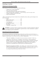
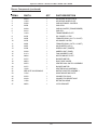
Mounting the Furnace
After selecting a safe and appropriate location for
your furnace, construct the mounting system as
required by the location and the following
specifications.
Ceiling Mounting
CAUTION: Ensure that your furnace
mounting system can safely bear the
suspended weight of the furnace and allow safe
servicing of furnace components.
Raised Platform Mounting
CAUTION: Make sure the platform is
designed to safely bear the weight of the
furnace and allow safe servicing of furnace components. The platform must be constructed of
non-combustible materials (e.g. steel).
1.
IF THERE IS NO POTENTIAL FOR GASOLINE FUMES
IN YOUR SERVICE AREA, YOU MAY MOUNT THE
FURNACE ON A RAISED PLATFORM WHICH IS
MINIMUM 2 FEET (61 CM) HIGH
3.
Refer to Figures 4A and 4B.
Follow the instructions as provided in the
diagrams.
Use a spirit level to make sure the cabinet
is level side to side and front to back.
8 FOOT (2.5 METERS) MINIMUM FROM FLOOR
TO FURNACE IF THERE IS THE POTENTIAL FOR
GASOLINE FUMES IN YOUR SERVICE AREA
1.
2.
CB-2800 FURNACE
Refer to Figure 4C and follow the
instructions as provided in the diagram.
FIGURE 4C - Furnace Installed on
Raised Platform
4-5
Operator's Manual: Models CB-1400, CB-1800, and CB-2800
Mounting the Furnace (continued)
Floor Mounting
CAUTION: If you are installing your furnace in an area with a combustible floor, you must
construct a non-combustible floor as shown in Figure 4D. Refer to NFPA-31 or CSA-B-139.
1.
Refer to Figure 4D and follow the instructions as provided in the diagram.
MIN. 24 GA. STEEL PAN WITH MIN. 1 INCH
(2.5CM) LIP FOR OIL CONTAINMENT
MIN. 18" (46 CM)
CB-2800 FURNACE
MIN. 18" (46 CM)
8 INCH (20 CM) TALL CINDER BLOCK
MIN. 24 GA. STEEL
FIREGUARD SHEETROCK OR EQUIVALENT
MIN. 2" (5 CM) TALL MASONRY BLOCKS TO
ALLOW CLEARANCE FOR INSTALLATION OF
FITTINGS ON THE CONNECTOR BLOCK
COMBUSTIBLE MATERIAL
FIGURE 4D - Furnace Installed on Non-Combustible Floor
4-6
Operator's Manual: Models CB-1400, CB-1800, and CB-2800
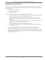
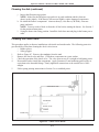
Determining the Type of Oil Tank
It is very important that you determine which type of oil tank your furnace will be using, as this will
determine the correct method for installing your oil pump and oil lines. Oil tanks are classified in three
categories as follows:
(1) Inside Above Ground Tank
(2) Outside Above Ground Tank
(3) Underground Tank
Ensure that your tank installation adheres to the following safety guidelines:
• The tank installation must meet all national and local codes. Consult your Clean Burn dealer
and local municipal authorities for more information if necessary.
• Use a minimum 250-gallon tank. DO NOT use a 55-gallon drum as a substitute for an
appropriate tank. The tank must be large enough to allow water, sludge, etc. to settle out of
the used oil.
• The tank must have a manual shut-off type valve on the side of the tank to allow the water,
sludge, etc. to be drained from the bottom of the tank.
• All unused openings in the tank must be plugged or capped off.
• The tank must be vented to the outside of the building using iron or steel pipe and fittings
with an approved vent cap.
1.
2.
Review the following three figures (4E/4F/4G) which illustrate the different types of oil
tank/pump installations, and select the one which matches your site's tank installation.
Carefully review the appropriate tank/pump installation details, including the pump installation
and specifications for the oil line installation. (Procedures for installing these components can be
found in the following sections.)
4-7
Operator's Manual: Models CB-1400, CB-1800, and CB-2800
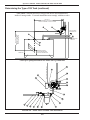
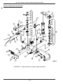
Determining the Type of Oil Tank (continued)
CAUTION: National and local codes govern the use and installation of
inside oil storage tanks. Your tank installation must comply with these codes.
OIL FLOW
MAX. 30 FT.
HORIZONTAL SUCTION LINE
OR NOT TO EXCEED 10" HG OF VACUUM
MAX. 10 FT.
VERTICAL SUCTION LIFT
OR NOT TO EXCEED
10" HG OF VACUUM
SUCTION OIL LINE
FILL PIPE WITH
RAINTIGHT CAP
VENT PIPE WITH
VENT CAP
CLEAN-OUT
MINIMUM 12 INCHES
(30.5 CM) FROM CHECK
VALVE TO TANK BOTTOM
PUMP ELECTRICAL CIRCUIT
Close-up of pump installation for inside above ground tank
FIGURE 4E - Inside Above Ground Tank Installation
4-8
Operator's Manual: Models CB-1400, CB-1800, and CB-2800
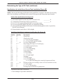
Determining the Type of Oil Tank (continued)
Specifications for Inside Above Ground Tank Installation (Figure 4E)
NOTE: Review the following specifications closely and fill-in as required. Procedures for oil pump
and oil line installation can be found in the sections following the tank illustrations/specifications.
Suction Line Specifications (Per Figure 4E)
(1)
(2)
(3)
(4)
(5)
Horizontal length of suction line (NOT to exceed 30 ft.)
__________ ft.
Vertical lift of suction line (NOT to exceed 10 ft.)
__________ ft.
Use 5/8" O.D. copper tubing; DO NOT use steel pipe unions.
Use only good flare fittings; DO NOT use compression fittings.
Seal every threaded fitting with Permatex #2 non-hardening gasket sealer or equivalent;
DO NOT use teflon tape.
(6) Ensure that the suction line is 100% airtight.
Tank/Pump Installation Component Specifications (Per Figure 4E)
Number
(1)
(2)
(3)
(4)
(5)
(6)
(7)
(8)
(9)
(10)
(11)
(12)
(13)
(14)
(15)
(16)
(17)
(18)
(19)
(20)
(21)
Quantity
1*
1*
1
1
_____ ft.
2
1
1
3**
1*
1*
1
1
1*
1
1
1
_____ ft.
1
1
3
Description
Check valve
Check valve screen
1/2" I.D. steel pipe (standpipe)
2" x 1/2" tap double tap hex bushing
5/8" O.D. copper tubing
Flare fitting (5/8" flare x 1/2" NPT male)
1/2" stainless steel ball valve
1/2" close nipple
3/4" x 1/2" hex bushing
Lenz canister filter
Vacuum gauge
1/2" street elbow
6" x 1/2" pipe nipple
Oil pump
1/4" close nipple
1/4" x 1/2" bell reducer
___" x 1/4" NPT flare fitting (size correctly for pressure oil line)
Pressure oil line (size according to chart in Oil Line Installation section)
1/2" close nipple
4" x 2" x 2" electrical box
Locking rings to attach box to pump motor
* Provided as stock part with furnace.
** Two bushings are provided with furnace.
4-9
Operator's Manual: Models CB-1400, CB-1800, and CB-2800
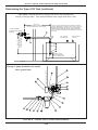
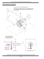
Determining the Type of Oil Tank (continued)
CAUTION: National and local codes govern the use and installation of
outside oil storage tanks. Your tank installation must comply with these codes.
MAX. 30 FT.
HORIZONTAL SUCTION LINE
OR NOT TO EXCEED 10" HG OF VACUUM
OIL PUMP ASSEMBLY
MOUNTED ON WALL INSIDE
BUILDING
CAUTION: THE SUCTION LINE FOR AN OUTSIDE OIL STORAGE
TANK MAY REQUIRE HEAT TAPING TO ALLOW THE OIL TO FLOW
DURING COLD WEATHER. DO NOT INSTALL TANK OUTSIDE IF
WINTER TEMPERATURES ARE SEVERE. ADDING UNTREATED
FUEL OIL TO USED OIL DURING COLD WEATHER MAY CAUSE THE
OIL TO GEL.
MAX. 10 FT.
VERTICAL SUCTION LIFT
OR NOT TO EXCEED
10" HG OF VACUUM
FILL PIPE WITH
RAINTIGHT CAP
VENT PIPE WITH
VENT CAP
MINIMUM 12 INCHES
(30.5 CM) FROM CHECK
VALVE TO TANK BOTTOM
BUILDING
OUTSIDE OIL STORAGE TANK WITH CONTAINMENT
PUMP ELECTRICAL CIRCUIT
Close-up of pump installation for outside
above ground tank
FIGURE 4F - Outside Above Ground Tank Installation
4-10
Operator's Manual: Models CB-1400, CB-1800, and CB-2800
Determining the Type of Oil Tank (continued)
Specifications for Outside Above Ground Tank Installation (Figure 4F)
NOTE: Review the following specifications closely and fill-in as required. Procedures for oil pump
and oil line installation can be found in the sections following the tank illustrations/specifications.
Suction Line Specifications (Per Figure 4F)
(1)
(2)
(3)
(4)
(5)
Horizontal length of suction line (NOT to exceed 30 ft.)
__________ ft.
Vertical lift of suction line (NOT to exceed 10 ft.)
__________ ft.
Use 3/4" O.D. copper tubing; DO NOT use steel pipe unions.
Use only good flare fittings; DO NOT use compression fittings.
Seal every threaded fitting with Permatex #2 non-hardening gasket sealer or equivalent;
DO NOT use teflon tape.
(6) Ensure that the suction line is 100% airtight.
Tank/Pump Installation Component Specifications (Per Figure 4F)
Number
(1)
(2)
(3)
(4)
(5)
(6)
(7)
(8)
(9)
(10)
(11)
(12)
(13)
(14)
(15)
(16)
(17)
(18)
(19)
(20)
(21)
Quantity
1*
1*
1
1
_____ ft.
2
1
1
1**
1*
1*
1
1
1*
1
1
1
_____ ft.
1
1
3
Description
Check valve
Check valve screen
3/4" I.D. steel pipe (standpipe)
2" x 3/4" tap double tap hex bushing
3/4" O.D. copper tubing
Flare fitting (3/4" flare x 3/4" NPT male)
3/4" stainless steel ball valve
3/4" close nipple
3/4" x 1/2" hex bushing
Lenz canister filter
Vacuum gauge
1/2" street elbow
6" x 1/2" pipe nipple
Oil pump
1/4" close nipple
1/4" x 1/2" bell reducer
___" x 1/4" NPT flare fitting (size correctly for pressure oil line)
Pressure oil line (size according to chart in Oil Line Installation section)
1/2" close nipple
4" x 2" x 2" electrical box
Locking rings to attach box to pump motor
* Provided as stock part with furnace.
** Two bushings are provided with furnace.
4-11
Operator's Manual: Models CB-1400, CB-1800, and CB-2800
Determining the Type of Oil Tank (continued)
CAUTION: National and local codes govern the use, installation, and monitoring of
underground oil storage tanks. Your tank installation must comply with these codes.
MAX. 30 FT.
HORIZONTAL SUCTION LINE
OR NOT TO EXCEED 10" HG OF VACUUM
WHEN USING AN UNDERGROUND TANK, YOU MUST CONSIDER
THE FOLLOWING:
CAUTION: BEFORE BURYING ANY LINES, MAKE SURE TO
THOROUGHLY TEST THE FURNACE SYSTEM. MAKE SURE THE
SUCTION LINE IS 100% AIRTIGHT. ANY LEAKS WILL RESULT IN
REPEATED LOSS OF PUMP PRIME.
OIL PUMP ASSEMBLY
MOUNTED ON WALL INSIDE
BUILDING
FILL PIPE WITH
RAINTIGHT CAP
SUCTION OIL LINE
MAX. 10 FT.
VERTICAL SUCTION LIFT
OR NOT TO EXCEED
10" HG OF VACUUM
CONTAINMENT
DO NOT INSTALL CHECK VALVE ON OIL PICK
UP. SEE PUMP DETAIL FOR LOCATION OF
CHECK VALVE.
MINIMUM 12 INCHES (30.5 CM)
FROM OIL PICK UP TO TANK BOTTOM
UNDERGROUND OIL STORAGE TANK
Close-up of pump installation for underground tank
FIGURE 4G - Underground Tank Installation
4-12
VENT PIPE WITH
VENT CAP
Operator's Manual: Models CB-1400, CB-1800, and CB-2800
Determining the Type of Oil Tank (continued)
Specifications for Underground Tank Installation (Figure 4G)
NOTE: Review the following specifications closely and fill-in as required. Procedures for oil pump
and oil line installation can be found in the sections following the tank illustrations/specifications.
CAUTION: The underground suction line must be installed in appropriate containment and
must comply with all applicable national and local codes.
Suction Line Specifications (Per Figure 4G)
(1)
(2)
(3)
(4)
(5)
Horizontal length of suction line (NOT to exceed 30 ft.)
__________ ft.
Vertical lift of suction line (NOT to exceed 10 ft.)
__________ ft.
Use 3/4" O.D. copper tubing; DO NOT use steel pipe unions.
Use only good flare fittings; DO NOT use compression fittings.
Seal every threaded fitting with Permatex #2 non-hardening gasket sealer or equivalent;
DO NOT use teflon tape.
(6) Ensure that the suction line is 100% airtight.
(7) DO NOT install the check valve in the tank.
Tank/Pump Installation Component Specifications (Per Figure 4G)
Number
(1)
(2)
(3)
(4)
(5)
(6)
(7)
(8)
(9)
(10)
(11)
(12)
(13)
(14)
(15)
(16)
Quantity
_____ ft.
2
1
1
1
1*
1*
1
1
1*
1
_____ ft.
1
1
3
N.A.
Description
3/4" O.D. copper tubing
Flare fitting (3/4" flare x 3/4" NPT male)
3/4" street elbow
3/4" stainless steel ball valve
3/4" close nipple
Lenz canister filter
Vacuum gauge
3/4" male x 1/2" female street elbow
6" x 1/2" pipe nipple
Oil pump
___" x 1/4" NPT flare fitting (size correctly for pressure oil line)
Pressure oil line (size according to chart in Oil Line Installation section)
1/2" close nipple
4" x 2" x 2" electrical box
Locking rings to attach box to pump motor
Pump electrical circuit
* Provided as stock part with furnace.
4-13
Operator's Manual: Models CB-1400, CB-1800, and CB-2800
Installing the Oil Pump
After determining the type of oil tank your furnace installation will use, you can proceed by installing the
oil pump accordingly.
1.
2.
3.
4.
Study the specifications for oil pump installation provided in the appropriate tank/pump
installation diagram (either Figure 4E, 4F, or 4G).
Also refer to the oil pump installation diagram provided in this section (Figure 4H).
Adhere to the following guidelines:
• Install the oil pump in a location where it can be easily primed and serviced. Its location
must be protected from water and combustible fumes. DO NOT mount the pump in a
basement or on the floor.
• The oil pump can push the oil much further than it can suck the oil. It is therefore very
important that the pump be positioned as close to the oil tank as possible.
• Mount the pump inside the building to protect it from weather/exposure.
• Position the pump to minimize the height and length of the suction oil line (i.e. the oil
line from the pump to the tank). DO NOT exceed the following limits, or your pump will
not operate correctly:
Maximum suction line lift - 10 feet (or not to exceed 10" of vacuum)
Maximum horizontal run - 30 feet
• Measure the suction line lift and horizontal run for your installation and write this
information on the appropriate tank diagram in the spaces provided (either Figure 4E, 4F,
or 4G).
• The oil pump requires a single oil line. DO NOT install a return line to the tank unless
instructed to do so by your Clean Burn dealer.
• Whenever possible, mount the pump above the highest oil level in the tank, so the pump
is suction fed, not gravity or pressure fed.
ATTENTION: If your pump is gravity or pressure fed, DO NOT install check valves, or
severe damage to the oil pump seals and oil spillage will occur. Oil pressure at the pump
inlet may not exceed 3 psi. Refer to NFPA-31.
Install the oil pump according to the instructions and specifications provided in the diagrams.
4-14
Operator's Manual: Models CB-1400, CB-1800, and CB-2800
Installing the Oil Pump (continued)
OIL FLOW
PUMP MOUNTED ON WALL
NOTE: THE ARROW ON
THE PUMP HEAD SHOWS
DIRECTION OF MOTOR
ROTATION. DIRECTION OF OIL
FLOW IS OPPOSITE TO THE
ARROW ON THE PUMP HEAD.
INSTALL THE VACUUM GAUGE IN
ONE OF THE GAUGE PORTS ON
THE OUTLET SIDE OF THE FILTER.
STAINLESS STEEL
BALL VALVE TO ALLOW
SERVICEMAN TO
VACUUM TEST THE
PUMP
MAKE SURE TO SEAL ALL
THREADED FITTINGS, INCLUDING
THE PLUG IN THE UNUSED GAUGE
PORT AND THE STEM OF THE
VACUUM GAUGE, WITH
PERMATEX #2
NON-HARDENING GASKET SEALER
OR EQUIVALENT.
MOUNTING SURFACE
HORIZONTAL AXIS
MOUNTING SURFACE
NOTE: MAKE SURE TO INSTALL THE PUMP HORIZONTALLY. THE PUMP CAN
BE ROTATED 90 DEGREES ALONG ITS HORIZONTAL AXIS FOR WALL
MOUNTING. THE PUMP HEAD CAN ALSO BE ROTATED ON THE MOUNT 180
DEGREES.
CAUTION! NEVER MOUNT THE PUMP VERTICALLY WITH THE PUMP HEAD
POINTING UP OR DOWN.
Figure 4H - Detail of Pump Installation for Above Ground Inside/Outside Tank
4-15
Operator's Manual: Models CB-1400, CB-1800, and CB-2800
Wiring the Furnace and Pump
WARNING: To avoid electrical shock, make sure that power to the furnace is turned OFF
before connecting any wires. A licensed electrician should install all wiring to your furnace. All
wiring must be in accordance with the National Uniform Electrical Code and local codes. Properly size
all wires and use electrical conduit for all electrical lines.
Wiring your furnace involves the installation of two lines:
(1) A dedicated electrical line to the furnace
(2) A pump electrical circuit from the furnace to the oil pump
Necessary wiring specifications are provided in this section and in the Wiring Schematics located in
Appendix B at the back of the manual.
Wiring to the Furnace
1.
2.
3.
Install a dedicated electrical circuit to the electrical junction box on the furnace.
CAUTION: DO NOT tie into an existing circuit, or electrical overload may occur.
Wire the furnace according to the Wiring Schematic in Appendix B.
Check for correct voltage at the furnace, and refer to the following chart.
ATTENTION: Incorrect voltage will severely damage the blower motor/furnace components.
DO NOT operate your furnace on any non-specification power system.
UNIT HEATER
Model
CB-1400
CB-1800
CB-2800
Voltage
110/120
110/120
110/120
Breaker Size*
20 amps
20 amps
20 amps
Circuit
Dedicated
Dedicated
Dedicated
Hertz
60
60
60
*NOTE: Breaker size with optional equipment is 30 amps. When installing any
optional equipment (e.g. air compressor or draft inducer), you must use a 30 amp breaker. Make
sure a qualified electrician properly sizes and installs this electrical circuit.
CENTRAL FURNACE
Model
Voltage
CB-1800
110/120
CB-2800
110/120
4.
Breaker Size
30 amps
30 amps
Circuit
Dedicated
Dedicated
Hertz
60
60
DO NOT turn on main power until instructed to do so.
Wiring to the Oil Pump
NOTE: DO NOT wire the pump directly into your building's electrical system. The pump must be
activated (receive power from) the burner via the pump electrical circuit.
1.
2.
Install the pump electrical circuit from the furnace to the oil pump location.
Wire the pump circuit according to the Wiring Schematic (Appendix B).
4-16
Operator's Manual: Models CB-1400, CB-1800, and CB-2800
Installing the Oil Lines
Your furnace installation requires two oil lines:
(1) Suction oil line: oil line and suction line components from the tank to the pump.
(2) Pressure oil line: oil line from the pump to the connector block on the furnace.
Procedures and specifications for the installation of the oil lines follow.
ATTENTION: Be sure to purchase copper tubing which is sized correctly for your installation.
Undersizing of oil lines restricts oil flow and results in poor furnace performance. Refer to the tables in
this section listing the proper sizing of the suction and pressure oil lines.
Installing the Suction Oil Line
1.
2.
3.
Study the specifications on the appropriate Tank/Pump installation diagram (either Figure 4E,
4F, or 4G).
Make sure you have purchased all the necessary fittings to complete the installation correctly.
Install the fittings and components as shown in the appropriate Tank/Pump installation diagram.
Also adhere to the following guidelines:
• DO NOT exceed line lengths and suction limits of the pump. Keep the suction line and
suction lift as short as posssible.
Maximum suction line lift - 10 feet (or not to exceed 10" of vacuum)
Maximum horizontal run - 30 feet
• Use properly sized copper tubing according to the following chart:
Type of Tank
Inside Tank
Outside Tank
Underground Tank
Minimum Size of Copper Tubing*
5/8" O.D.
3/4" O.D.
3/4" O.D.
*NOTE: Maximum allowable size of tubing is 1" O.D. for all
types of tanks.
•
•
•
Ensure that the suction line is 100% airtight. The pump cannot properly suck oil from the
tank if there are any leaks in the suction oil line. Air leaks in the suction line due to improper
installation will result in repeated burner shutdown and unnecessary service calls.
Use only good flare fittings. DO NOT use compression fittings or pipe unions on the suction
line. The use of these inappropriate materials on the suction line will result in air leaks and
burner shutdown.
Seal each threaded fitting with #2 Permatex non-hardening gasket sealer or equivalent. DO
NOT use teflon tape. Teflon residues will plug vital pump and burner components and will
void your warranty.
4-17
Operator's Manual: Models CB-1400, CB-1800, and CB-2800
Installing the Suction Oil Line (continued)
4.
5.
Install the canister filter in the suction line according to the specifications on the appropriate
Tank/Pump diagram (either Figure 4E, 4F, or 4G).
NOTE: DO NOT install the canister filter in the pressure oil line. This filter must be
installed in the suction oil line to protect the pump head. Ensure that the filter can be easily
accessed for cleaning.
Install the vacuum gauge in one of the ports of the canister filter. Ensure that all fittings on the
canister filter are 100% airtight.
Installing the Pressure Oil Line
1.
2.
3.
Study the specifications on the appropriate Tank/Pump installation diagram (either Figure 4E,
4F, or 4G).
Make sure you have purchased all the necessary fittings to complete the installation correctly.
Install the fittings and components as shown in the appropriate Tank/Pump installation diagram.
Also adhere to the following guidelines:
• Properly size the pressure oil line according to the following chart:
Length of Pressure Line
Minimum Size of Copper Tubing
Length up to 50 feet
Length up to 100 feet
Length up to 200 feet
1/2" O.D.*
5/8" O.D.*
3/4" O.D.*
*Diameter of copper tubing must be maintained for full line length.
•
Local codes may require the installation of "oil thermo cut-off" safety valves. Be sure to
check all appropriate codes to ensure compliance.
Installing the Compressed Air Line
NOTE: Your air compressor system must supply air pressure to the furnace with the following
requirements:
• 50 psi
• water trap or dryer
If you do not have shop air, an optional air compressor is available. Contact your local Clean Burn
dealer for more information.
1.
2.
3.
Run a compressed air line from your shop air to the connector block on the furnace. Use
minimum 1/4" O.D. copper tubing or equivalent for the compressed air line.
Install an easily accessible shut-off valve in the air line so the burner can be serviced without
shutting off the shop air in your service area.
If necessary, install a pressure regulator (additional to the burner air regulator) in the air line, and
set it at 50 psi.
ATTENTION: DO NOT feed full shop air pressure to the burner or damage to burner
components may occur.
4-18
Operator's Manual: Models CB-1400, CB-1800, and CB-2800
Installing the Compressed Air Line (continued)
4.
Install a water trap or extractor/dryer in the air line with an automatic drain so compressed air
(rather than water) is supplied to the burner.
NOTE: Water must not be fed to the burner, or the flame will be extinguished and the
burner will shut down. Be sure to drain water from your compressor tank on a regular basis to
keep water out of the air line.
Installing the Stack
WARNING: Inappropriate stack materials or improper stack design/installation can adversely
affect the proper, safe operation of your furnace. Contact your Clean Burn dealer to purchase the
proper stack components for your furnace.
Stack designs are generally classified as follows:
(1) "Class A" stack through the ceiling of the building
(2) "Class A" stack through the sidewall and up the side of the building
Figures 4I and 4J illustrate these stack designs. Choose the stack design which is appropriate for your
furnace installation and review all specifications provided in the Figure. When designing your stack,
adhere to the following specifications:
• Models CB-1400/CB-1800/CB-2800 require minimum 8" I.D. stack components.
• Ensure that the vertical stack height is at least 10 feet. If needed, increase the vertical length
of the stack or install a draft inducer to obtain -.02" W.C. draft over fire. (Section 8 contains
details on adjusting the draft.)
• Keep the horizontal stack run as short as possible; slant it upward at a minimum of 1/4" per
foot or run.
• Keep the stack design simple. Complicated stacks (with long runs and many turns) reduce
draft and result in poor burner performance. Your stack may include only one 90 degree turn.
All other stack turns must be at 45 degrees or less to ensure optimal draft and burner
performance.
NOTE: If you plan to use an existing masonry chimney, the chimney must be inside the building.
Exterior masonry chimneys chill the stack gases and result in poor draft and poor burner performance.
ATTENTION: If you have an exhaust fan(s) in your shop, it is critical that you have adequate
make up air (source of fresh air to replace the stale air exhausted by the fan). When an exhaust fan is
run without adequate make up air, the resultant vacuum in the building will draw combustion products
back into the burner. This back draft causes poor burner performance and may damage vital burner
components. Refer to Section 8 in this manual for additional information concerning exhaust fans and
proper make up air.
Stack components should be installed in the following order:
(1) Inside stack (the stack components from the furnace breach to within 18" of the ceiling, roof,
or sidewall of your building)
(2) Barometric damper
(3) "Class A" stack penetration through the ceiling, roof, or sidewall
(4) "Class A" stack on the exterior of the building
(5) "Class A" stack cap
4-19
Operator's Manual: Models CB-1400, CB-1800, and CB-2800
2 FT. (61 CM)
10 FT. (3 M) MINIMUM VERTICAL
STACK HEIGHT
"CLASS A" STACK CAP
NON-RESTRICTIVE TYPE TO ALLOW
FREE FLOW OF THE STACK GASES
NOTE: THE LAST STACK SECTION SHALL EXTEND AT
LEAST 2 FEET (61 CM) ABOVE THE HIGHEST POINT AT
WHICH IT COMES IN CONTACT WITH THE ROOF AND AT
LEAST 2 FEET (61 CM) HIGHER THAN ANY RIDGE,
PARAPET, WALL, OR ROOF STRUCTURE WITHIN 10 FEET
(3 M) OF IT.
10 FT. (3 M)
WATERTIGHT
ROOF FLASHING
FOR CB1400/1800/2800 USE
MIN. 8-INCH STACK
COMPONENTS.
SINGLE WALL STACK
MIN. 24 GAUGE
"CLASS A" KIT FOR INSTALLING
"CLASS A" STACK THROUGH CEILING
BAROMETRIC
DAMPER
-.02 W.C. DRAFT OVERFIRE IS
ESSENTIAL FOR PROPER FURNACE
OPERATION. SEE SECTION 8.
CLEAN-OUT TEE
OR ELBOW
Figure 4I - Installation of "Class A" Stack Through Roof/Ceiling
4-20
Operator's Manual: Models CB-1400, CB-1800, and CB-2800
WARNING! OUTSIDE STACK AND STACK PENETRATIONS THROUGH CEILING,
ROOF, OR SIDEWALL MUST BE "CLASS A" FOR FIRE SAFETY AND TO MAINTAIN
PROPER DRAFT.
EXTERIOR SINGLE WALL STACK DOES NOT MEET FIRE CODE!
"CLASS A" STACK CAP
NON-RESTRICTIVE TYPE TO ALLOW
FREE FLOW OF THE STACK GASES
WARNING! MAKE SURE TO INSTALL ALL STACK COMPONENTS WITH PROPER
SUPPORT AND CLEARANCES FROM CONBUSTIBLES. FOLLOW STACK
MANUFACTURER'S SPECIFICATIONS.
CLASS A STACK
PENETRATION
AND CLEAN-OUT
TEE
BAROMETRIC
DAMPER
-.02 W.C. DRAFT OVERFIRE IS
ESSENTIAL FOR PROPER FURNACE
OPERATION. SEE SECTION 8.
AIR PRESSURE LINE
SINGLE WALL STACK
MIN. 24 GAUGE
OIL PRESSURE LINE
Figure 4J - Installation of "Class A" Stack Through Sidewall
4-21
"CLASS A" STACK COMPONENTS
INSULATED STACK WITH A STAINLESS STEEL LINER
FOR CB1400/1800/2800 USE
MIN. 8-INCH STACK
COMPONENTS.
10 FT. (3 M) MINIMUM VERTICAL STACK HEIGHT
NOTE: THE LAST STACK SECTION SHALL EXTEND AT LEAST 2 FEET (61 CM)
ABOVE THE HIGHEST POINT AT WHICH IT COMES IN CONTACT WITH THE ROOF
AND AT LEAST 2 FEET (61 CM) HIGHER THAN ANY RIDGE, PARAPET, WALL, OR
ROOF STRUCTURE WITHIN 10 FEET (3 M) OF IT.
Operator's Manual: Models CB-1400, CB-1800, and CB-2800
Installing the Interior Stack
WARNING: Single wall stack components may be used only for those portions of the stack
which are located inside your building and away from any fire/burn hazards. All single wall
stack components must be located a minimum 18 inches from combustibles.
1.
2.
Install the single wall stack with proper clearances from combustibles. Also ensure that the stack
is located a safe distance from all shop personnel.
Install an elbow or clean-out tee at the junction of the horizontal and vertical stack components
to allow for easy cleaning of the stack.
ATTENTION: Avoid additional 90-degree turns in the stack. Each additional 90-degree turn
slows down stack gases, creates back-pressure, and results in repeated burner shutdown and
unnecessary service calls. All other turns in the stack should be at a 45-degree (or smaller) angle.
NOTE: IMPORTANT for Canadian Installations - Local codes may require the installation of
a clean-out tee.
Installing the Barometric Damper
1.
2.
3.
Refer to Figure 4K. Install a single wall tee (min. 24 gauge) on the first straight vertical or
horizontal stack section within one to three feet of the furnace breach.
NOTE: This tee is required to support the barometric damper. You must purchase this tee when
you purchase your stack materials (8" single wall tee - CB#71074).
Install the barometric damper in the opening of the tee. Use a small spirit level to make sure that
it is properly level as shown.
Install one self-tapping screw at the BOTTOM of the barometric damper to hold it in place.
DO NOT install this screw at the top of the barometric damper, or the flapper of the damper will
not operate correctly.
NOTE: Specifications for adjusting the barometric damper for proper draft overfire are provided in
Section 8 of this manual.
8" CLEAN BURN BAROMETRIC DAMPER
INSTALLED IN SINGLE WALL TEE
ADJUST THIS WEIGHT TO
OBTAIN PROPER DRAFT
I88539
Figure 4K - Installation of Barometric Damper
4-22
Operator's Manual: Models CB-1400, CB-1800, and CB-2800
Installing the Stack Penetration
CAUTION: When running the stack through your ceiling, roof, or sidewall, you must use a
proper insulated "Class A" penetration with a stainless steel liner. DO NOT run single-wall stack
through your ceilng, roof or sidewall. Single-wall penetrations do not meet safety codes and may create
a fire hazard. Provide proper clearances to combustibles per all applicable codes.
1.
2.
Refer to Figure 4I/4J as needed.
Follow the installation instructions provided by the stack manufacturer.
Installing the Exterior Stack
ATTENTION: All exterior stack pieces must be insulated "Class A" ("all fuel") stack components with
a stainless steel liner. DO NOT use "Class B" natural gas stack components. DO NOT use single-wall
stack for your exterior stack. Single-wall exterior stack chills the stack gases and results in poor draft
and poor burner performance.
1.
2.
3.
Refer to Figure 4I or 4J as needed.
Follow the installation instructions provided by the stack manufacturer.
Install water-tight roof flashing around the penetration of the exterior stack.
NOTE: Clean Burn recommends the use of "Dektite" roof flashing (or equivalent) which
ensures a water-tight seal when installed properly. Contact your local Clean Burn dealer for
details.
Installing the Stack Cap
NOTE: Proper installation of a "Class A" stack cap ensures the free flow of stack gases which is
essential for optimal burner performance.
1.
2.
Refer to Figure 4I or 4J as needed. Your stack cap should be classified as: "Class A"
non-restrictive, "fuel-oil type".
Install the stack cap according to the manufacturer's instructions.
4-23
Operator's Manual: Models CB-1400, CB-1800, and CB-2800
Installing the Wall Thermostat
ATTENTION: Before installing the round Honeywell thermostat, remove the red shipping tab.
DO NOT turn the dial on the thermostat until the red shipping tab has been removed, or serious damage
to the thermostat will occur!
1.
2.
3.
4.
5.
Select a location for the thermostat on an interior wall away from the furnace and cold drafts.
Run "two wire" (minimum 18 gauge) thermostat cable between the burner and the thermostat.
Remove the yellow jumper wire from the "T" terminals of the oil primary control. Save this
jumper wire for use during pump priming.
Connect the thermostat wires to the two "T" terminals on the oil primary control.
Follow the manufacturer's instructions to wire the thermostat.
Inspecting the Furnace Installation
Following completion of all installation activities described in this chapter, the furnace should be inspected by qualified personnel before firing. This ensures that your installation meets all applicable
national and local codes and allows for any deficiencies to be corrected before furnace startup. Improper
installation may void your warranty.
4-24
Operator's Manual: Models CB-1400, CB-1800, and CB-2800
SECTION 5: OIL PUMP PRIMING
Understanding Oil Pump Priming
Preparing your Clean Burn furnace for operation begins with priming the oil pump. This activity
involves a series of separate procedures as follows:
(1) Preparing the Canister Filter for Pump Priming
(2) Preparing the Pump for Pump Priming
(3) Preparing the Burner for Pump Priming
(4) Activating the Pump
(5) Establishing Proper Oil Flow
(6) Flushing the Oil Lines
(7) Adjusting the Pump Pressure
NOTE: The procedures in this section must be performed in sequence without interruption to properly
prime the pump.
Required Tools and Materials
The following tools and materials are required for oil pump priming and should be gathered before
starting any procedures:
•
•
•
•
3/8" open-end wrench
Rags
Two containers (minimum one-gallon)
Medium straight-blade screwdriver
5-1
Operator's Manual: Models CB-1400, CB-1800, and CB-2800
Preparing the Canister Filter for Pump Priming
ATTENTION: Fill the canister filter with used oil so the pump gears are charged with oil during the
priming procedure. DO NOT use new motor oil; it will probably not ignite at the burner. DO NOT run
the pump with dry gears, or the pump will not prime and damage may occur.
1.
Refer to Figure 5A.
2.
Remove the four (4) bolts holding the canister bowl in place, then remove the bowl.
3.
Check the condition of the filter element and O-ring.
4.
Make sure the O-ring is in the groove on the top of the filter element. Push the element into
position on the filter body.
5.
Fill the canister with used oil to prevent the pump from running dry during priming.
6.
Check the condition of the canister O-ring, and re-install the canister. Tighten the four canister
bolts evenly to ensure that the canister filter is 100% airtight.
USE A RATCHET WITH A 6-INCH EXTENSION AND
3/16-INCH "ALLEN" SOCKET TO REMOVE THE
FOUR "ALLEN" BOLTS
Figure 5A - Oil Canister Detail
5-2
Operator's Manual: Models CB-1400, CB-1800, and CB-2800
Preparing the Pump for Pump Priming
1.
2.
3.
4.
Refer to Figure 5B.
Use a 3/8" wrench to open the bleeder port on the pump head (two to three full turns) so the
bleeder is completely open.
Fill a small squeeze bottle with used oil, and squirt a few shots of used oil into the bleeder on the
pump. This ensures that the pump gears are charged with oil so the pump can pull an adequate
vacuum to prime.
Position a one gallon container (minimum) under the bleeder port to catch oil which will flow
from the bleeder during pump priming.
PRESSURE ADJUSTMENT
BLEEDER PORT
FIGURE 5B - Bleeder Port on Pump Head
5-3
Operator's Manual: Models CB-1400, CB-1800, and CB-2800
Preparing the Burner for Pump Priming
NOTE: It is necessary to allow the burner to warm up at least 15 minutes prior to activating the burner
during the pump priming sequence. The proving switch on the preheater block will not allow the burner
to start until the block is hot.
1.
Turn the switch on the wall thermostat to OFF.
NOTE: If your thermostat does not have an OFF setting, disconnect one thermostat wire so the
burner will not run.
2.
Turn the main power to the furnace ON.
3.
Refer to Figure 5C.
4.
Disconnect the oil line at the connector block on the furnace.
5.
Position a one-gallon container (minimum) to catch oil which will flow from the disconnected oil
line during pump priming.
NOTE: It is important to thorougly flush the oil line during pump priming so that no dirt/debris
is fed to the burner.
6.
Loosen the locking nut on the oil regulator, and turn the knob two to three full turns counter
clockwise so the oil regulator is completely shut off.
7.
Loosen the locking nut on the air regulator.
AIR LINE
OIL LINE
CONNECTOR BLOCK
COMPRESSED AIR LINE
PRESSURE OIL LINE
FIGURE 5C - Detail of Burner Connections
5-4
Operator's Manual: Models CB-1400, CB-1800, and CB-2800
Activating the Pump
IMPORTANT NOTE: Activating the pump for pump priming involves running the burner by jumping
the "F" terminals of the oil primary control. This procedure (i.e. jumping the "F" terminals) should be
used only for this specific purpose--never for normal operation. This procedure is accomplished easily
by two people: one at the burner and one at the wall thermostat.
ATTENTION: When performing this procedure, never jump from an "F" terminal to a "T" terminal, or
severe damage to the primary control will occur.
1.
2.
3.
4.
5.
6.
7.
8.
9.
10.
Refer to Figure 5D, Step 1.
Locate the yellow jumper wire which you removed and saved during installation of the wall
thermostat.
Connect the jumper wire to one "F" terminal on the primary control.
Refer to Figure 5D, Step 2.
Turn the switch on the wall thermostat to HEAT, and adjust the thermostat above room
temperature.
The burner should start running.
Immediately turn the knob on the air regulator clockwise until the air gauge registers 15 psi. You
will adjust the air pressure further during burner startup and operation.
NOTE: No air pressure will register on the air gauge until the burner starts running.
The pump should start running.
Within ten seconds, jump the "F" terminals by connecting the jumper wire to the other "F"
terminal.
NOTE: If the safety reset on the primary control activates and the burner stops running while
performing this procedure, follow the instructions in Section 7 to reset the oil primary control
and restart the burner.
Run the burner and pump until proper oil flow has been established and the oil lines have been
completely flushed out. (See the following procedures for specific instructions.)
CAD CELL WIRES
CAD CELL WIRES
CAD CELL WIRES
F2
F2
F2
F1
F1
F1
T2
T2
T2
T1
T1
T1
JUMPER WIRE
JUMPER WIRE
THERMOSTAT WIRE
THERMOSTAT WIRE
STEP ONE
STEP TWO
STEP THREE
FIGURE 5D - Jumping the Oil Primary Control
ATTENTION: Never touch a jumper wire from an "F" terminal to a "T" terminal on the oil
primary control. This will severely damage your primary control. Make sure that the plastic
barrier strip is in place between the "F" and "T" terminals as shown in Figure 5D.
5-5
Operator's Manual: Models CB-1400, CB-1800, and CB-2800
Establishing Proper Oil Flow at the Pump
1.
2.
3.
Within one minute after opening the bleeder port, oil should be sputtering from the port. Make
sure the container is positioned to catch the oil flowing from the port.
ATTENTION: If no oil flows within one minute, shut the pump off and call your Clean Burn
dealer. DO NOT run the pump "dry"--doing so may damage the gear set.
Observe the oil flow at the bleeder port until a steady stream (no fluctuations or sputtering) is
achieved. Bleed approximately one quart of oil from the open port to ensure an airtight suction
line.
NOTE: If the oil stream continues to fluctuate or sputter, there is a leak(s) in the suction
line. Any leak(s) in the suction line must be repaired to ensure that the suction line is 100%
airtight.
Close the port with a 3/8" wrench and tighten completely.
Flushing the Oil Lines
1.
2.
3.
4.
Go back to the burner (at the disconnected oil line). Observe a steady oil flow until one gallon
has been collected; this ensures that all air and debris have been flushed from the oil line.
Turn the power OFF so the burner and pump motors stop running.
Re-connect the oil line to the connector block.
Remove the jumper wire from the "F" terminals, and make sure the cad cell wires are now
connected to the "F" terminals as illustrated in Figure 5D, Step 3. Save the jumper wire for
future pump priming.
Adjusting the Pump Pressure
NOTE: It is not necessary to adjust pump pressure for most furnace installations. Adjust the pump
pressure only if either of the following conditions exist:
• The distance between the pump and the furnace is less than 50 feet.
• You are burning light viscosity oil such as #2 fuel oil. (In this case, you may also need to
install a nozzle with a smaller orifice. Contact your Clean Burn dealer before proceeding.)
1.
2.
3.
Refer to Figure 5B.
Turn the set screw counterclockwise with a small, straight-blade screwdriver until the screw is
flush with the nipple. DO NOT back the set screw out more than this!
Turn the adjustment screw clockwise one full turn to set the pump pressure at approximately
20 psi.
5-6
Operator's Manual: Models CB-1400, CB-1800, and CB-2800
SECTION 6: STARTING AND ADJUSTING THE BURNER
Understanding Burner Startup and Adjustment
Starting and adjusting the burner involves a series of separate procedures which must be accomplished
in sequence without interruption. Review all the procedures before attempting burner startup and
adjustment, paying careful attention to safety information statements.
Preparing the Burner for Startup
1.
2.
3.
4.
5.
Turn the switch on the wall thermostat OFF.
NOTE: If your thermostat does not have an OFF setting, disconnect one thermostat wire so
the burner will not run.
Turn the main power to the furnace ON.
Wait at least 15 minutes until the preheater block is thoroughly warmed up. (Feel the back of the
burner box to make sure the preheater is sufficiently warm. The proving switch on the preheater
block will not allow the burner to start until the block is hot.)
NOTE: The preheater block will remain warm as long as power is supplied to the burner. If the
main power supply is ever turned OFF, you must wait at least 15 minutes until the preheater
block is thoroughly warm before starting the burner.
Refer to Figure 6A to locate
the oil and air regulators.
Loosen the locking nuts on
the oil and air regulators.
Turn the adjustment knobs on
the oil and air regulators
counterclockwise until 1/2"
of the threads on the knobs
are exposed. DO NOT back
the knobs all the way out.
NOTE: The air and oil
gauges will not show any
pressure until the burner
starts. Before starting
the burner for the first time, it
is very important to turn both
the air and oil regulators
completely OFF as described
in this step.
AIR REGULATOR
LOCKING NUTS
OIL REGULATOR
AIR GAUGE
OIL GAUGE
COMBUSTION
AIR BAND
I88312
FIGURE 6A - Component Detail of the CB-525-S2 Burner
6-1
Operator's Manual: Models CB-1400, CB-1800, and CB-2800
Preparing the Burner for Startup (continued)
6.
Initial Adjustment of the Combustion Air Band:
WARNING: The combustion air band must be properly adjusted to ensure that the burner
ignites and burns correctly. DO NOT attempt to start the burner with the combustion air band
wide open or completely closed. The burner may not ignite correctly. Failure to heed this warning may
result in a fire or explosion hazard.
• Refer to Figure 6A to locate the combustion air band.
• Rotate the combustion air band to adjust it to the appropriate initial slot opening as listed
in the following Initial Adjustment Charts. Use a ruler to accurately set the slot
opening at the widest section of the slot.
IMPORTANT NOTE: This initial setting of the combustion air band will allow you to start the burner.
You will fine tune the combustion air band further as described later in these instructions.
ATTENTION: The settings shown in the charts below are only initial adjustments. Final
adjustments must be done by inspecting the flame length according to the illustrations
provided on the following page.
Initial Adjustments for CB-1400
Maximum Input = 140,000 BTUH @ 1.0 GPH with CB525-S2 Burner
Oil Type
Oil PSI / Flame Length
Air PSI
Air Band
Nozzle
#2 Fuel Oil*
Used Crankcase Oil
Used ATF
Used Hydraulic Oil
9-5
9-5
9-5
9-5
1.5 & check flame length
2.0 & check flame length
1.5 & check flame length
1.5 & check flame length
12
12
15
12
1/4"
1/4"
1/4"
1/4"
Initial Adjustments for CB-1800
Maximum Input = 185,000 BTUH @ 1.3 GPH with CB525-S2 Burner
Oil Type
Oil PSI / Flame Length
Air PSI
Air Band
Nozzle
#2 Fuel Oil*
Used Crankcase Oil
Used ATF
Used Hydraulic Oil
9-5
9-5
9-5
9-5
2.5 & check flame length
3.0 & check flame length
3.5 & check flame length
3.0 & check flame length
14
14
14
14
3/8"
3/8"
3/8"
3/8"
Initial Adjustments for CB-2800
Maximum Input = 280,000 BTUH @ 2.0 GPH with CB525-S2 Burner
Oil Type
Oil PSI / Flame Length
Air PSI
Air Band
Nozzle
#2 Fuel Oil*
Used Crankcase Oil
Used ATF
Used Hydraulic Oil
9-5
9-5
9-5
9-5
5.5 & check flame length
6.5 & check flame length
5.5 & check flame length
5.0 & check flame length
16
16
16
16
5/8"
5/8"
5/8"
5/8"
*If you are burning light viscosity oils such as #2 fuel oil, it may be necessary to install a smaller nozzle. Call
your Clean Burn dealer for more information.
6-2
Operator's Manual: Models CB-1400, CB-1800, and CB-2800
Starting the Burner
1.
Turn the switch on the wall thermostat to HEAT and adjust the thermostat setting above room
temperature to start the burner.
2.
Adjusting the Air Regulator:
As soon as the burner starts running, turn the knob on the air regulator clockwise to achieve
proper operating air pressure. Refer to the Initial Adjustment Charts.
3.
Within ten seconds, turn the knob on the oil regulator clockwise until the oil regulator gauge
shows 1 psi and the burner ignites. Do not exceed 1 psi at this time. Instructions are provided
later in this section for adjusting the oil regulator to the proper flame length.
NOTE: If the safety reset on the primary control is activated and the burner stops running, see
Section 7 for further instructions on restarting your burner.
4.
Adjusting the Oil Regulator:
While adjusting the oil regulator, visually inspect the
CAUTION
flame length through the observation port. Refer to
WHEN OPENING INSPECTION PORT
Figure 6B for an illustration of the desired flame length.
The flame should extend no more than one-half of the
PORT MAY BE HOT
PROTECT HANDS
way down the combustion chamber.
WEAR
SAFETY GOGGLES
WARNING: The observation port gets hot as the
KEEP
FACE AWAY
burner fires. To avoid personal injury, always wear
OPEN PORT SLOWLY
heavy work gloves and safety glasses when opening the port
and viewing the flame.
NOTE: The CB525-S2 burner features a unique oil regulator system which regulates the oil after it has
been heated to 140 degrees F. At this temperature, the difference in viscosity between various used oils
is minimal, and the need for adjusting the oil regulator is significantly reduced. Additionally, this burner
allows for fine tuning to accommodate the particular blend of used oils being burned. It is also designed
to operate at low ambient temperatures with minimal adjustment.
Correct Maximum Flame Adjustment
(Proper Oil and Air Pressure):
• Flame goes half of the way down the
combustion chamber.
• Flame does not touch back or walls of
combustion chamber.
Incorrect Flame Adjustment
(Oil Pressure Too High):
• Flame must not touch back or walls of
combustion chamber.
Incorrect Flame Adjustment
(Air Pressure Too High):
• Ensure proper air pressure setting.
FIGURE 6B - Flame Length Adjustment
6-3
Operator's Manual: Models CB-1400, CB-1800, and CB-2800
Starting the Burner (continued)
5.
6.
7.
8.
Check the flame length after the burner has fired for 15 minutes. If necessary, adjust the oil
regulator to fine tune the flame.
Tighten the locking nuts on the oil regulator and the air regulator.
NOTE: After initial startup, check the flame length at least weekly and readjust as necessary.
Fine Tuning the Combustion Air Band:
NOTE: The initial setting of the combustion air band may require additional adjustment.
• Refer to Figure 6A to identify the combustion air band location on the burner.
• Observe the flame. The flame should be yellow-white with sharp tips and no "sparkles."
• If the flame is orange in color, the oil you are burning requires MORE combustion air.
OPEN the air band 1/8" to 1/4", and re-check the flame for the proper characteristics.
• Re-check the flame after five minutes--you should see a yellow-white flame with sharp
tips and no "sparkles."
Checking for a Smokeless Burn:
Check for a smokeless burn by observing the stack while the burner is running. If you see any
smoke, repeat the previous steps for setting the combustion air band and adjusting the air
regulator. After adjusting the combustion air band, re-check the flame length.
NOTE: Check for a smokeless burn periodically (as you do the flame length). Immediately
readjust the burner if you ever see smoke coming from the stack. Smoke indicates improper air/
fuel adjustment.
NOTE: When using instruments to adjust the burner for a smokeless burn, the following
readings should be achieved:
• Draft over fire should be -.02 inch w.c.
• Adjust for a smoke spot of a trace to 2
• Adjust for a CO2 reading of 8 to 10% or an O2 reading of 7 to 9%
• Cad cell reading below 500 ohms
Checking the Operation of the Fan/Blower Motor
NOTE: It is important to verify that the fan/blower motor operates correctly to ensure that the fan limit
control is properly cycling the fan/blower motor as described below. Also refer to Appendix A at the
back of the manual for additional information on the fan limit control.
1.
Start the burner and adjust it as described previously in this section.
2.
The fan/blower motor will not start until the burner has been running for 5 to 15 minutes to heat
up the combustion chamber and heat exchanger. At this point, the fan limit control will activate
the fan/blower motor.
3.
Once the fan/ blower motor has activated, turn the burner off by turning the wall thermostat to
OFF.
4.
With the burner off, the fan/blower motor should continue to run for 5 to 10 minutes until the
combustion chamber is cooled down. The fan limit control will then shut off the fan/blower
motor.
WARNING: If the fan/blower motor does not operate as described, immediately shut down
your furnace to avoid potential equipment damage and/or fire hazard. Contact your Clean Burn
dealer immediately.
6-4
Operator's Manual: Models CB-1400, CB-1800, and CB-2800
SECTION 7: RESETTING THE OIL PRIMARY CONTROL
Understanding the Oil Primary Control
The oil primary control will go into safety lockout and shut the burner off when it detects flame-out
during burner operation. The oil primary control will then wait approximately one to two minutes and
attempt to re-ignite the burner (recycle mode). If the burner does not re-ignite, the control will shut the
burner off on safety. The following procedure explains what should be done when this occurs. It is very
important that you follow these instructions precisely when resetting the safety on the primary control
and restarting the burner.
Using the Reset Button
DANGER! DO NOT push the reset button more than once! DO NOT push the reset button if
oil mist is present in the combustion chamber or when the combustion chamber is hot! DO NOT
operate your furnace if excess oil, oil vapor or fumes have accumulated in or near your furnace. As with
any oil burning furnace, improper operation may result in a fire or explosion hazard.
1.
2.
3.
4.
5.
Refer to Figure 7A.
Check the combustion chamber for fuel mist by shining a flashlight through the observation port.
If you see fog (fuel mist) in the chamber, DO NOT push the reset button.
If the combustion chamber is hot, allow the furnace to cool for at least 30 minutes. DO NOT
push the reset button.
When you are sure all mist has been cleared from the chamber and the combustion chamber is
cool, depress the red button on the primary control for a minimum of three (3) seconds, then
release. Reset the control ONCE ONLY.
If the burner will not restart, call your Clean Burn dealer immediately.
WARNING
CAD CELL WIRES
DO NOT PUSH
RESET BUTTON
(Refer to Owner's Manual First)
F2
F1
ATTENTION: Never touch a
jumper wire from an "F"
terminal to a "T" terminal on
the oil primary control. This will
severely damage your primary
control. Make sure the plastic
barrier strip is in place between
the "F" and "T" terminals as
shown in Figure 7A.
T2
T1
RESET BUTTON
THERMOSTAT WIRE
FIGURE 7A - Oil Primary Control
7-1
Operator's Manual: Models CB-1400, CB-1800, and CB-2800
7-2
Operator's Manual: Models CB-1400, CB-1800, and CB-2800
SECTION 8: ADJUSTING THE DRAFT OVER FIRE
Understanding the Importance of Draft
Draft in the furnace is created as the hot combustion gases rise up the stack, creating a negative pressure
inside the stack and the furnace. This negative pressure is measured as inches of water column (W.C.)
of draft. A proper draft overfire of -.02 w.c. is essential so that all combustion products travel away
from the burner, down the combustion chamber, through the furnace flues and up the stack.
Checking for Correct Draft Over Fire
WARNING: Correct draft over fire is
essential for the proper and safe operation
of your furnace.
Your furnace is equipped with an observation/
draft reading port to check draft over fire. A
qualified serviceman with proper equipment must
check/adjust your furnace for proper draft. Contact your Clean Burn dealer for this service.
1.
2.
Insert the probe of the draft gauge
instrument into the draft reading port in
the observation port as shown in
Figure 8A.
NOTE: Follow the directions with the
draft gauge to use your specific type of
gauge.
Note the draft overfire reading on the draft
gauge.
ATTENTION: The draft reading should
be in the -.02 to -.04 w.c. range. Poor
draft (i.e. -.01 to +.08) results in back
pressure in the furnace and poor burner
performance. Too much draft (i.e. -.06 to
-.12) sucks the heat from the furnace and
results in abnormally high stack
temperature.
I88257
FIGURE 8A - Checking for Proper
Draft Over Fire
8-1
Operator's Manual: Models CB-1400, CB-1800, and CB-2800
Adjusting the Barometric Damper
NOTE: If the draft overfire is not in the -.02 to -.04 w.c. range, it is necessary to adjust the barometric
damper.
1.
2.
3.
4.
5.
Before starting the burner, turn the weight
on the flapper COUNTERCLOCKWISE
until the flapper remains closed. This will
provide maximum draft for the furnace.
Follow the directions in Section 6 to start
and adjust the burner.
With the burner running, check the draft
overfire with a draft gauge.
As shown in Figure 8B, adjust the weight
on the flapper to obtain a consistent
-.02 w.c. draft overfire. Turn the weight
COUNTERCLOCKWISE to increase draft
(i.e. draft increases as the flapper closes).
Turn the weight CLOCKWISE to decrease
draft (i.e. draft decreases as the flapper
opens).
Tighten the locking nut to securely hold
the weight in position.
ADJUST THIS WEIGHT
TO OBTAIN PROPER
DRAFT OVERFIRE
BAROMETRIC DAMPER
I88258
Figure 8B - Adjustment of Barometric Damper
Solving Draft Overfire Problems
WARNING: If you cannot achieve proper draft overfire, do not operate your furnace!
Contact your Clean Burn dealer for assistance.
ATTENTION: Backdraft must be resolved or your furnace will not operate correctly!
Under backdraft conditions, draft overfire readings will show positive pressure in the combustion
chamber. Backdraft means that oil spray, combustion products, and heat are blown back against the
burner. Backdraft results in oil-fouled retention heads and electrodes. Severe backdraft will force heat
back against the burner and result in heat damage to the cad cell and transformer.
Backdraft is caused by the following conditions:
• Poor draft caused by improper stack design. (See Section 4.)
• Poor draft caused by improper adjustment of the barometric damper.
• Incorrect combustion air band setting on the burner. (See Section 6.)
• Furnace flues are plugged with ash. (See Section 9.)
• Clean-out gasket on clean-out doors is out of position. (See Section 9.)
• Exhaust fans in your building are sucking gases down the stack.
8-2
Operator's Manual: Models CB-1400, CB-1800, and CB-2800
Understanding the Effect of Exhaust Fans on Draft
Any type of exhaust fan, paint booth, or exhaust system in a building will create negative pressure in the
building unless there is a source of make-up air (i.e. fresh air which enters the building and replaces the
air removed by the exhaust fans.) Refer to Figure 8C on the following page.
If there is insufficient make-up air, the exhaust fan will suck air and combustion gases down the furnace
stack and create backdraft in the furnace. Even if the exhaust fan is on another level of the building or in
another room away from the furnace, the exhaust fan will still create backdraft at the furnace.
Checking Draft Overfire to Determine Severity of Backdraft
The following procedure is an accurate method of determining how much backdraft is created by the
exhaust fans. Once this is determined, you can select the correct method for resolving the backdraft.
Refer to Figure 8C on the following page as needed.
1.
2.
3.
4.
Turn off ALL exhaust fans and close ALL doors and windows in the building (any open door or
window will allow make-up air to enter the building and will negate the test).
Start the furnace and adjust the barometric damper so that the draft overfire is -.02 w.c.
Check the draft overfire again. Now have someone start the exhaust fans.
Note how much the draft overfire has changed.
ATTENTION: If the draft overfire changed towards positive, it is mandatory that make-up air
is provided to the building or severe damage to the furnace and burner will occur (voiding the
warranty). If the draft overfire remained constant at -.02 w.c., there is sufficient make-up air
entering the building, and the exhaust fan is not adversely affecting the draft.
8-3
Operator's Manual: Models CB-1400, CB-1800, and CB-2800
PROPER DRAFT
BACKDRAFT
OIL SPRAY AND HEAT IS FORCED BACK AGAINST THE
BURNER AND RESULTS IN OIL-FOULED ELECTRODES AND
RETENTION HEAD. SEVERE BACKDRAFT WILL HEAT DAMAGE
THE CAD CELL AND TRANSFORMER.
BACKDRAFT CREATED BY
EXHAUST FAN
EXHAUST FAN CREATES BACKDRAFT IN STACK
DRAFT OVERFIRE OF -.02 W.C. MEANS
COMBUSTION GASES ARE FLOWING
AWAY FORM THE BURNER, THROUGH
THE FURNACE FLUES AND UP THE
STACK.
EXHAUST FAN CREATES BACKDRAFT IN STACK AND SUCKS
COMBUSTION GASES DOWN THE STACK AND BACK INTO THE
FURNACE.
RISING HOT COMBUSTION GASES PRODUCE DRAFT
RISING HOT COMBUSTION GASES
PRODUCE DRAFT IN THE STACK
SERVICEMAN ADJUSTS
BAROMETRIC DAMPER TO
OBTAIN -.02 W.C. DRAFT
OVERFIRE
BACKDRAFT
COMBUSTION GASES
PROPER DRAFT
Figure 8C - Proper Draft vs. Backdraft
8-4
COMBUSTION AIR TO
BURNER
Operator's Manual: Models CB-1400, CB-1800, and CB-2800
Installing a Make-up Air Louver
Exhaust Fans and Make-up Air Louvers
When exhaust fans are operated in tight buildings, there is little or no source of fresh air to replace the
air removed from the building by the exhaust fan. This results in negative pressure (vacuum) in the
building which creates severe backdraft problems at the furnace.
Properly sized make-up air louvers are designed to allow adequate fresh air to enter the building during
operation of the exhaust fans. The louvers automatically open under the vacuum created by the exhaust
fans. The louvers open just enough to provide the correct CFM of fresh air. The louvers automatically
close when the exhaust fans are turned off.
Sizing the Make-up Air Louver
Procedure 1: (a) Determine the CFM rating of the exhaust fan. This information should be stamped on
a label on the exhaust fan. Make sure to add up the total CFM if more than one
exhaust fan exists in the building.
(b) Select the correct size of make-up air louver to provide the required CFM of fresh air.
If you cannot determine the CFM rating of the exhaust fan, use the following procedure.
Procedure 2: (a) With all exhaust fans running, open one of the large bay doors so that it is just 2 feet
open. Position a helper at this door.
(b) Start the furnace and check for proper -.02 w.c. draft overfire.
(c) As you watch the draft gauge, instruct your helper to slowly close the large bay door.
When the draft overfire is affected, stop closing the door.
(d) Open the large bay door just enough to allow the draft overfire to return to a proper
-.02 w.c. The size of this opening represents the approximate size of the make-up air
louver required.
(e) Measure the size of the opening and calculate the square inches. Select a make-up air
louver that is at least 10% larger than this opening.
Example of Calculations for Sizing Make-up Air Louver
1. Opening Size
12' (144") x 1' (12") = 12 square feet (1728 (square inches)
2. Add 10%
1728 square inches x 1.1 = 2000 square inches
3. Louver Size
Select 48" x 48" louver = 2304 square inches
(Installation instructions are provided on the next page)
8-5
Operator's Manual: Models CB-1400, CB-1800, and CB-2800
Installing the Make-up Air Louver
NOTE: It is very important to follow these instructions carefully to ensure proper performance of the
louver.
1.
2.
3.
The louver must not be close to the furnace. The fresh air should travel at least 40 to 50 feet
before reaching the furnace so the air warms up. The furnace will not heat well if it is receiving
cold return air.
The louver must be high in the sidewall of the building so the cold fresh air does not blow across
the floor level and chill the service personnel.
The louver should be installed in the opposite wall from the location of the exhaust fan. This
will quickly vent diesel exhaust from the top of the building and reduce the amount of run time
for the exhaust fan.
8-6
Operator's Manual: Models CB-1400, CB-1800, and CB-2800
SECTION 9: MAINTENANCE
Understanding Maintenance
Maintaining your Clean Burn furnace is an important activity which includes several periodic maintenance activities and an annual burner tune-up...all are necessary to keep your furnace running in peak
condition. Failure to maintain and/or improper servicing by unqualified personnel may adversely affect
the proper, safe operation of your furnace, may reduce the service life of your furnace, and may void
your warranty.
The following chart summarizes all the maintenance activities which should be performed on the furnace
at the intervals indicated. Instructions/procedures for these activities are included in this chapter.
Maintenance Activity
Cleaning the canister filter
Cleaning out ash
Cleaning the check valve/screen
Cleaning water/sludge out of tank
Annual burner tune-up
Interval
Before vacuum gauge reads 10" HG of vacuum
At least twice a year; more often with heavy use
At least once a year
At least once a year
At least once a year
NOTE: IMPORTANT! Record all maintenance activities in the Maintenance Record provided in the
Appendixes.
Annual Burner Tune-up
Your Clean Burn furnace requires annual preventative maintenance--similar to an automotive tune-up-to keep it running in peak condition. Contact your local Clean Burn dealer to schedule the annual
preventative maintenance which is usually (preferably) performed during warm weather to prepare the
furnace for the next heating season. The burner tune-up should be performed by Clean Burn certified
technicians.
9-1
Operator's Manual: Models CB-1400, CB-1800, and CB-2800
Cleaning the Canister Filter
NOTE: Never operate your furnace with more than 10" HG of vacuum on the suction side of the pump.
High vacuum separates air from the oil and results in erratic burner operation.
The following protective gear should be worn when cleaning the filter:
• Rubber gloves
• Safety goggles
1.
Close the ball valve adjacent to the filter.
2.
Position a container under the filter.
3.
Unscrew the four bolts to drain the oil from the canister.
4.
Remove the canister bowl.
5.
Clean the screen and the bowl in a parts washer.
6.
Referring to Figure 9A, examine the filter components as you reassemble them.
7.
Check the condition of the O-rings. Replace any that are cracked or worn.
8.
Ensure that the canister filter is 100% airtight by firmly tightening the four bolts.
9.
Open the ball valve. Refer to Sections 5 and 6 for instructions on priming the pump and starting
the burner.
USE A RATCHET WITH A 6-INCH EXTENSION AND
3/16-INCH "ALLEN" SOCKET TO REMOVE THE
FOUR "ALLEN" BOLTS
FIGURE 9A - Canister Filter Component Detail
9-2
Operator's Manual: Models CB-1400, CB-1800, and CB-2800
Cleaning Ash from the Furnace
NOTE: The maintenance interval for cleaning ash from the furnace is approximately 700 hours of
operation as indicated on the hour meter on the burner. Be sure to clean the ash from your furnace at
least twice during the heating season. Your furnace may require more frequent clean out of the ash due
to contaminants in the oil or heavy use. As ash accumulates, furnace heat output declines, and the stack
temperature rises. 1/8" of ash has the insulating capacity of one inch of fiberglass insulation and reduces
heat transfer significantly. Never allow more than 1/4" of ash to accumulate in the combustion chamber,
heat exchanger flues, or stack.
CAUTION: Be aware that used oils may contain heavy metallic compounds or foreign
materials. When burned, these compounds are deposited within the furnace, necessitating
careful cleaning. Make sure you use a sturdy ladder or scaffolding for safe access to ceiling-hung
furnaces.
NOTE: When cleaning the furnace, static electricity may build up in the shop vac hose. If this occurs,
use #12 copper wire wrapped around the hose with the other end connected to the furnace (or other
ground source) to eliminate the static.
The following protective gear should be worn when cleaning the ash:
• Respirator for fine particles
•Rubber gloves
• Safety goggles
•Protective clothing
1.
2.
3.
Ensure that power has been turned OFF, and all "hot" components have been allowed to cool
sufficiently. Allow at least one hour for the ceramic target to cool.
Clean out the burner throat:
a. Disconnect the burner power cable.
b. Remove the lock-down nut and swing the burner open.
c. Clean out the burner throat using a small scraper to remove the residues.
ATTENTION: Keep the burner open (swung out) so that you do not knock or bend burner
components when cleaning out the combustion chamber.
Clean the ash from the stack components:
a. Brush accumulated ash from the stack cap.
b. Lightly tap the stack components to loosen the ash.
c. Allow ash and dust to settle in the clean-out tee or elbow.
d. Vacuum ash from the clean-out tee, or disconnect the stack and vacuum ash from the elbow.
9-3
Operator's Manual: Models CB-1400, CB-1800, and CB-2800
Cleaning the Ash
(continued)
4.
Remove the clean-out
door(s) to clean ash from
inside the combustion
chamber (see Figure 9B):
a. Disconnect the stack
from the furnace breach.
b. Remove the clean-out
panel from the back of
the furnace.
c. Remove the cross brace
(Model CB-2800 only).
d. Remove the clean-out
door(s) to expose the
CB-1800 is shown here.
heat exchanger flues and
CB-1400 is similar.
the combustion chamber.
e. Check the color of the
ash--it should be light
gray or tan.
ATTENTION: White
ash indicates excessive air
pressure. Black ash or
soot indicates too
much oil pressure. If
these conditions exist,
call your Clean Burn
dealer. DO NOT overfire
your furnace by turning
up the compressed air
and/or oil pressure.
Overfiring will damage
the combustion chamber
and heat exchanger and
CB-2800 is shown here.
will void your warranty.
f. Use your shop vac to
vacuum ash from the flues. Figure 9B - Accessing the Combustion Chamber for Cleaning
NOTE: Avoid "packing" the ash in the back of the tubes by first vacuuming the flues before
pushing the flue brush down the flues.
g. Use a flue brush to thoroughly clean the flues.
h. Thoroughly vacuum any remaining ash residue from the flues.
i. Check the flues for rust.
ATTENTION: The presence of rust in the flues indicates that chlorinated materials are
being burned. Burning chlorinated materials will severely damage your heat exchanger and
void your warranty. Contact your Clean Burn dealer for instructions to test your oil for
chlorine contamination before firing your furnace.
9-4
Operator's Manual: Models CB-1400, CB-1800, and CB-2800
Cleaning the Ash (continued)
j. Inspect the fiberglass rope gasket.
NOTE: Make sure the fiberglass rope gasket is in good condition and the clean-out
door(s) seal(s) tightly. If the door(s) does not seal tightly, replace damaged components.
k. Re-install the furnace components: clean-out door(s), cross brace (CB-2800), clean-out
panel, and stack.
NOTE: You may need to bleed air from the oil line before starting the burner. See Section 5
for the pertinent instructions.
l. Swing the burner into firing position. Install the lock-down nut and plug in the burner power
cable.
Cleaning the Check Valve
This procedure applies to furnace installations with inside and outside tanks. The following protective
gear should be worn when cleaning the check valve/screen:
• Rubber gloves
• Safety goggles
1.
Refer to Figure 9C. Remove the standpipe from the tank.
2.
Remove the check valve and filter. Clean these components in a parts washer.
3.
Check the operation of the check valve. The valve must seat so it is airtight to hold pump prime.
4.
Re-assemble and re-install the components. Apply Permatex #2 non-hardening gasket sealer or
equivalent to the threaded fittings. Firmly tighten all connections so the suction line is 100%
airtight.
5.
Follow pump priming instructions in Section 5 to re-establish prime.
SUCTION OIL LINE
STANDPIPE
CHECK VALVE
SCREEN
CLEAN-OUT
Figure 9C - Check Valve Detail
9-5
Operator's Manual: Models CB-1400, CB-1800, and CB-2800
Cleaning the Tank
DO NOT allow water, sludge, or other debris to accumulate in your oil supply tank to the point that noncombustible or harmful materials are drawn into the pump or burner.
Drain water and sludge from the bottom of your tank at least once a year, and more frequently with water
accumulation.
NOTE: If your used oil tank has not been cleaned on a regular basis, a considerable amount of sludge,
etc. may have accumulated on the bottom of the tank. Under these circumstances, it is advisable for you
to hire your used oil hauler to pump the tank. Make sure the tank is pumped to the bottom to remove all
sludge, etc. from the tank (your used oil hauler may charge an additional fee for this type of service).
The best time to pump the used oil tank is at the end of the heating season when the tank is low. This
allows sufficient time to refill the tank with used oil (generated by your company over the summer
months) so that you have adequate fuel for the heating season.
End of Season Maintenance
ATTENTION: Turn main power to your furnace OFF at the end of the heating season. EPA regulations allow your used oil to be burned only for "heat recovery." DO NOT operate your furnace during
warm weather just to burn oil, or severe damage to the combustion chamber/heat exchanger may occur.
Contact your local Clean Burn dealer to schedule your annual burner tune-up. Allow only trained,
authorized service personnel to service your burner.
9-6
Operator's Manual: Models CB-1400, CB-1800, and CB-2800
APPENDIX A
Detailed Furnace Specifications
FURNACE
SPECIFICATION
CB-1400
CB-1800
CB-2800
BTUH Input
Listed Fuels
140,000 @ 1.0 GPH
#2 Fuel Oil
Used Crankcase Oil
Used ATF
Used Hydraulic Oil
33.75 / 29.75 / 29.00
185,000 @ 1.3 GPH
#2 Fuel Oil
Used Crankcase Oil
Used ATF
Used Hydraulic Oil
40 / 30 / 28
280,000 @ 2.0 GPH
#2 Fuel Oil
Used Crankcase Oil
Used ATF
Used Hydraulic Oil
53 / 36 / 33
43.75 / 40.75 / 29.00
50 / 42 / 28
63 / 48 / 33
320
400
600
Ceiling Hung
Bench Tank Kit
Non-combustible
Platform
110/120 Volts, 60 Hz
20 Amps
Ceiling Hung
Bench Tank Kit
Non-combustible
Platform
110/120 Volts, 60 Hz
20 Amps
Ceiling Hung
Bench Tank Kit
Non-combustible
Platform
110/120 Volts, 60 Hz
20 Amps
N.A.
30 Amps
30 Amps
Refer to specifications
included with optional
accessories
24 Volt
Heat Anticipator
Setting: 0.2 Amps
Suntec J3NBN A132B
1/6 HP 1725 RPM
CCW shaft end
Lenz DH 750-100
8”
1/3
Three Blade / 21°
Honeywell L4064B
8” Probe
Hi-Limit – 200
Fan ON – 120
Fan OFF – 100
Refer to specifications
included with optional
accessories
24 Volt
Heat Anticipator
Setting: 0.2 Amps
Suntec J3NBN A132B
1/6 HP 1725 RPM
CCW shaft end
Lenz DH 750-100
8”
1/3
Four Blade / 16°
Honeywell L4064B
8” Probe
Hi-Limit – 200
Fan ON – 140
Fan OFF – 110
Refer to specifications
included with optional
accessories
24 Volt
Heat Anticipator
Setting: 0.2 Amps
Suntec J3NBN A132B
1/6 HP 1725 RPM
CCW shaft end
Lenz DH 750-100
8”
1/2
Four Blade / 20°
Honeywell L4064B
8” Probe
Hi-Limit – 200
Fan ON – 140
Fan OFF – 110
Cabinet Dimensions
(L x W x H, inches)
Furnace Dimensions
with Fan & Burner
(L x W x H, inches)
Approximate Weight
(lbs.)
Mounting
Electrical Requirements
Circuit Breaker for Unit
Heater
Circuit Breaker for
Central Furnace
Circuit Breaker for
Furnaces with Optional
Accessories
Wall Thermostat
Oil Pump
Pump Motor
Pump Motor Rotation
Canister Filter
Stack Size
Fan/Blower Motor HP
Fan Blade / Pitch
Fan Limit Control
Fan Limit Settings
A-1
Operator's Manual: Models CB-1400, CB-1800, and CB-2800
Burner Technical Specifications
NOTE: These burner specifications apply to all three furnace models--CB-1400, CB-1800, and
CB-2800.
Burner
CB-525-S2
Ignition Transformer
Carlin Transformer
14,000 volts
Nozzle
Delavan 9-5
Burner Motor
1/10 HP 3200 RPM
with centrifugal switch
Burner Motor Rotation
CCW shaft end
Compressed Air Requirements
2.0 CFM @ 20 PSI
Oil Primary Control
Carlin Oil Primary
Heater Element in Preheater Block
400 watts
Air Pressure Switch
MPL 808
Setting for Preheater Thermostat
140 degrees F
A-2
Operator's Manual: Models CB-1400, CB-1800, and CB-2800
Furnace Dimensions (CB-1400)
16.875
33.750
20.875
45.750
TOP VIEW (SHOWING MOUNTING LUGS)
WITH BURNER INSTALLED
29.750
23.125
29.000
16.250
SIDE VIEW (LOUVER SIDE)
FRONT VIEW (BURNER SIDE)
40.000
WITH FAN INSTALLED
33.750
Ø21.250
29.000
BACK VIEW (FURNACE BREACH SIDE)
SIDE VIEW (FAN SIDE)
I88545
A-3
Operator's Manual: Models CB-1400, CB-1800, and CB-2800
Furnace Dimensions (CB-1800)
CB-1800 Central Furnace
Overall Dimensions & Weight
with burner/blower package installed:
476 mm
70" L x 42" W x 28" H
Weight: 500 lbs.
765 mm
•
•
572 mm
TOP VIEW (SHOWING MOUNTING LUGS)
1045 mm
587 mm
394 mm
714 mm
1010 mm
SIDE VIEW (LOUVER SIDE)
FRONT VIEW (BURNER SIDE)
765 mm
714 mm
619 mm
1257 mm WITH FAN INSTALLED
SIDE VIEW (FAN SIDE)
BACK VIEW (FURNACE BREACH SIDE)
I88294
A-4
Operator's Manual: Models CB-1400, CB-1800, and CB-2800
Furnace Dimensions (CB-2800)
CB-2800 Central Furnace
Overall Dimensions & Weight
with burner/blower package installed:
648 mm
83" L x 48" W x 33" H
Weight: 700 lbs.
918 mm
•
•
902 mm
TOP VIEW (SHOWING MOUNTING LUGS)
1197 mm
1330 mm
591 mm
840 mm
584 mm
SIDE VIEW (LOUVER SIDE)
FRONT VIEW (BURNER SIDE)
1578 mm
619 mm
840 mm
918 mm
SIDE VIEW (FAN SIDE)
BACK VIEW (FURNACE BREACH SIDE)
I88295
A-5
Operator's Manual: Models CB-1400, CB-1800, and CB-2800
Burner Components
3
24
5
23
26
25
SEE ILLUSTRATION
I88543 FOR PARTS
NUMBER.
6
22
1
2
27
4
1
2
4
5
6
7
8
9
10
11
12
13
7
21
20
ALTERNATE
FASCO MOTOR
8
5
4
6
7
8
3
9
2
10
11
1
0
12
13
psi
14
15
9
20
30
40
10
0
50
psi
60
10
11
19
13
14
12
18
15
16
17
BURNER CB − 525 − S2
I88234
FIGURE A1 - Burner Component Detail
A-6
MAGNETEX MOTOR
Operator's Manual: Models CB-1400, CB-1800, and CB-2800
Burner Components (continued)
ITEM #
PART #
QTY
PART DESCRIPTION
1
26103
1
AIR INTAKE OUTER PLATE
2
11359
1
AIR INTAKE INNER PLATE
3
33188
1
CARLIN PRIMARY CONTROL
4
33335
1
ISOLATOR
5
33189
1
CARLIN IGNITER (TRANSFORMER)
6
33116
1
CAD CELL
7
11243
1
TRANSFORMER PLATE
8
32178
1
OIL GAUGE 0-15 PSI
9
32235
1
FEMALE ELBOW (3/16 T x 1/8 NPT)
10
32179
1
AIR GAUGE 0-60 PSI
11
32253
1
FEMALE ELBOW (1/8 TP x 1/8 NPT)
12
33297
1
HOUR METER (60 Hz)
13
33169
1
GREEN LIGHT (POWER)
14
33168
1
AMBER LIGHT (PUMP)
15
31113
1
FAN SQUIRREL CAGE
16
26044
1
MOTOR MOUNT PLATE
17
33175
1
BLOWER MOTOR
18
26053
1
RIGHT SIDE COVER
19
33370
1
CENTRIFUGAL SWITCH ASSEMBLY
20
33175
1
BLOWER MOTOR
21
13148
1
HEATER BLOCK ASSEMBLY
22
SEE NOTE ON DRAWING
23
11334
1
HINGE MOUNTING PLATE
24
33150
1
CONNECTOR PLUG
25
33149
1
CONNECTOR RECEPTACLE
26
11308
1
RETENTION HEAD
27
26052
1
LATCH BRACKET
NOZZLE ADAPTER ASSEMBLY
A-7
Operator's Manual: Models CB-1400, CB-1800, and CB-2800
Burner Components (continued)
58
30
57
(8)
31
56
55
32
(8)
59
54
1
3
33
34
53
2
35
4
52
36
51
27
50
6
5
39
40
47
26
(2)
12
(4) 17
29
38
48
(2)
10
37
49
11
7
29
45
41
25
28
42
46
43
9
44
8
13
14
15
1
2
3
4
5
6
7
24
8
9
10
11
12
13
16
19
17
21 (2)
20
22
18
FIGURE A2 - Preheater Block Assembly Component Detail
A-8
23
I88543
Operator's Manual: Models CB-1400, CB-1800, and CB-2800
Burner Components (continued)
ITEM #
PART #
QTY
PART DESCRIPTION
1
2
3
4
5
6
7
8
9
10
11
12
13
14
15
16
17
18
19
20
21
22
23
24
25
26
27
28
29
30
31
32
33
34
35
36
37
38
39
40
41
42
43
44
45
46
47
48
49
50
51
52
53
54
55
56
57
58
59
34169
33183
34165
32000
13150
32007
33298
33381
33418
32199
32050
32189
32043
54020
32201
33247
34036
26059
33057
26090
32190
32202
32201
33173
33041
32325
54020
33011
32359
14090
34148
34114
34147
34022
32306
32226
32364
32227
32360
32361
32223
32222
32221
32362
13142
32308
32309
33311
33312
33313
33314
33315
33316
33317
33318
33319
33320
33321
32322
1
1
1
1
1
1
1
1
1
1
2
2
1
1
2
1
4
1
1
1
2
1
1
1
1
1
1
1
2
1
8
8
2
2
2
2
2
2
2
2
2
2
2
2
2
2
2
2
2
2
2
2
2
2
2
2
2
2
2
ELECTRODE SCREW - 10-32 x 3/4
SINGLE PIECE ELECTRODE
WASHER
9 - 5 NOZZLE
NOZZLE ADAPTOR
PLUG - 1/8 NPT
140 WATTS HEATER
INSULATED CAP CRIMP CONNECTOR
THERMOSTAT L-130
PLUG - 1/16 NPT
SWIVEL FITTING
HEX NIPPLE - 1/8 NPT x 1-1/2
MALE CONNECTOR - 3/16T x 1/8 NPT
3/16 COPPER TUBING (OIL GAUGE LINE)
MACH. SCREW PHILLIPS HD. 6-32 x 3/8 Z
TERMINAL BLOCK
MACH. SCREW PHILLIPS HD. 6-32 x 1/4 Z
TERMINAL BLOCK BRACKET
AIR PRESSURE SWITCH
HEATER BLOCK
HEX NIPPLE - 1/8 NPT x 2
FEMALE ELBOW (FOR 1/4" AIR LINE)
FEMALE ELBOW (FOR 3/8" OIL LINE)
PRE-HEATER ELEMENT (400 WATTS)
PROVING SWITCH (NORMALLY OPEN)
MALE ELBOW 1/8 x 1/8 NPT (FOR AIR GAUGE LINE)
3/16 COPPER TUBING(OIL GAUGE LINE)
HEATER BLOCK THERMOSTAT(NORMALLY CLOSED)
REGULATOR SURFACE MOUNT
REGULATOR LOCK PLATE
REGULATOR MOUNTING SCREW
LOCK WASHER #8 Z
REGULATOR THREADED STEM
HEX NU T - 10-32 Z
BONNET
DIAPHRAGM RING
CAP AND BALL ASSEMBLY
COMPRESSION SPRING
DIAPHRAGM
BRASS POPPET SEAT
POPPET 'O" RING
POPPET VALVE
POPPET SPRING
BASE
REGULATOR KIT COMPONENTS
REGULATOR OUTER "O" RING
REGULATOR INNER "O" RING
SOLENOID INNER "O" RING
SOLENOID OUTER "O" RING
MANIFOLD MOUNT SOLENOID BODY
BODY "O" RING
PLUNGER ASSEMBLY
PLUNGER GUIDE ASSEMBLY
FLUX PLATE
WASHER SEAL
COIL
COIL HOUSING
NUT
AIR/OIL SOLENOID ASSEMBLY
A-9
Operator's Manual: Models CB-1400, CB-1800, and CB-2800
Burner Components (continued)
INSTALLATION OF THE SPINNER RETENTION HEAD
THE SPINNER RETENTION HEAD FITS INSIDE THE BURNER TUBE AND
REQUIRES (3) SELF-TAPPING SCREWS. IT IS VERY IMPORTANT THAT
THE SPINNER HEAD IS NOT TIPPED FROM SIDE TO SIDE OR FROM
TOP TO BOTTOM.
3X
VI
EW
EW
VI
A
A-
BB
USE PROVIDED SCREWDRIVER AS
WEDGE TO HOLD THE SPINNER
RETENTION HEAD IN POSITION. THEN
TIGHTEN THE THREE SCREWS TO
LOCK THE HEAD IN POSITION.
3/16" GAP
BETWEEN
ELECTRODES &
NOZZLE
CRITICAL DIMENSION:
NOZZLE MUST BE 1/8"
AHEAD OF THE DISK.
NOZZLE MUST NOT BE
BEHIND THE DISK.
1/8" SPARK
GAP
FRONT VIEW -- BB
SIDE VIEW -- AA
FIGURE A3 - Burner Electrode Specifications with Spinner Retention Head
A-10
Operator's Manual: Models CB-1400, CB-1800, and CB-2800
Burner Components (continued)
Model
CB-1400
CB-1800
CB-2800
Nozzle Size
Delavan 9-5
Delavan 9-5
Delavan 9-5
HEAD
DISTRIBUTOR
NOZZLE SIZE IS
STAMPED ON
FLAT OF
NOZZLE HEAD
ORIFICE
STEM
O-RING
Removing the Nozzle for Cleaning:
NOTE: Due to swivel fittings on the air and oil lines, it is not necessary to disconnect these lines
when swinging the burner open.
1.
Remove the lock-down nut on the mounting flange bolt.
2.
Disconnect the burner power cable.
3.
Carefully swing the burner open to its maintenance position.
4.
Remove the nozzle from the nozzle adapter with a 5/8" socket.
Cleaning the Nozzle:
1.
2.
3.
4.
5.
6.
7.
8.
Unscrew the stem from the nozzle head.
Spray WD-40 or equivalent through the orifice to thoroughly remove any blockage.
ATTENTION: DO NOT damage or deform the nozzle orifice; DO NOT use a torch tip
cleaner or other inappropriate device to clean the orifice. If the blockage is a "tarry"
material or a hard, black material, call your Clean Burn dealer for service.
Flush all components with WD-40 to remove oil residues.
Reassemble the nozzle components. When tightening the stem, just barely "snug" it down.
DO NOT overtighten.
Check the O-ring on the nozzle stem. Replace the O-ring if it is in the least bit cut or
deformed.
Lubricate the O-ring on the nozzle stem with a couple of drops of new motor oil, then reinstall the nozzle.
Check the electrodes for proper gap and clearances.
Re-install the burner and adjust for optimal performance as described in Section 6.
NOTE: If the nozzle plugs within a few days after cleaning, call your Clean Burn Dealer for
service.
FIGURE A4 - Cleaning the Nozzle
A-11
Operator's Manual: Models CB-1400, CB-1800, and CB-2800
Oil Pump Components
PUMP MOUNT
PUMP MOTOR
PUMP HEAD
COUPLING
CAUTION: WHEN REPLACING THE HEAD, MAKE SURE TO TIGHTEN THE LOCK SCREWS ON THE
COUPLING LAST (AFTER THE PUMP HEAD BOLTS HAVE BEEN TIGHTENED) SO THE PUMP AND
MOTOR BEARINGS ARE NOT COMPRESSED AND DAMAGED.
PUMP HEAD
STRAINER
COVER
COVER
GASKET
BOLT GASKET
COVER
BOLT
CAUTION: WHEN CLEANING THE PUMP HEAD STRAINER, INSTALL A NEW GASKET SO THE PUMP
HEAD IS AIRTIGHT. IF THE PUMP HEAD STRAINER IS CLOGGED, MAKE SURE TO CLEAN YOUR TANK
TO AVOID FURTHER CLOGGING.
FIGURE A5 - Oil Pump Components
A-12
Operator's Manual: Models CB-1400, CB-1800, and CB-2800
Oil Pump Components (continued)
Vacuum Testing the Oil Pump
Vacuum testing the oil pump is a very accurate way to
determine the following:
• The condition of the pump -- the ability of the
pump to pull a vacuum and suck oil from the tank.
• The condition of the fittings, gaskets and seals
from the ball valve to the pump -- these
components must all be airtight to avoid suction
leaks.
The following procedure provides instructions for
vacuum testing the pump and canister filter on systems
equipped with a ball valve.
BALL VALVE
IMPORTANT NOTE: For the pump to pull and hold
VACUUM GAUGE
vacuum, it is critical that all fittings are airtight.
Check the cover bolts, the 1/4" plug in the return port
and the acorn nut (on older style pumps only). If any
FIGURE A6 - Oil Pump System
of these fittings are loose, the pump may not pull a
vacuum or may lose the vacuum rapidly. It is also critical that all fittings in the suction line, including
fittings on the canister filter, are 100% airtight.
1.
Refer to Section 5: Oil Pump Priming in this manual. Follow the instructions to prime the oil
pump. NOTE: The oil pump will not pull a vacuum if the pump is dry. There must be oil in the
gears of the pump before the pump can pull a vacuum.
2.
With the pump running, open the bleeder two to three full turns, and make sure that oil is flowing
from the bleeder. DO NOT close the bleeder yet.
3.
Close the ball valve and observe the vacuum gauge. NOTE: The ball valve must have a
stainless steel ball and should be pressure tested by the manufacturer to ensure that it does not
leak. If the ball valve leaks, the vacuum test will not be accurate.
4.
The vacuum should increase within 15 seconds to 20 to 25 inches of vacuum. When the vacuum
gauge reads 20 to 25 inches of vacuum, first close and tighten the bleeder, then turn the pump
off.
NOTE: If the pump will not pull at least 20 inches of vacuum, there is a very serious suction
leak or the pump is damaged.
5.
If there are no suction leaks, the system will hold vacuum. NOTE: It is acceptable for the
vacuum to drop one to five inches within one minute as the seal in the pump seats. The vacuum
should then hold steady for 15 minutes.
IMPORTANT: If the vacuum drops more than one to five inches within the first minute, there is
one or more leaks somewhere between the pump and the ball valve. Do the following:
• Wipe your finger along the cylinder at the shaft of the pump. If there is oil here, the pump
seal is damaged. Replace the pump.
• Disassemble and clean all the fittings from the pump to the ball valve. Properly seal all
fittings with Permatex #2 non-hardening gasket sealer or equivalent. Check the condition of
the o-ring on the canister filter and tighten the four canister filter bolts in a crisscross pattern.
• Repeat the procedure to vacuum test the system to ensure that the system is air tight.
A-13
Operator's Manual: Models CB-1400, CB-1800, and CB-2800
Fan Limit Control
Understanding the Operation of the Fan Limit Control
The fan limit control senses air temperature within the furnace cabinet. This control contains two
switches: the limit switch and the fan switch.
Fan Switch: The fan switch is normally open and provides power to the fan (or blower). When the fan
limit control senses "Fan On" temperature, the fan switch closes and starts the fan (or blower). When
the wall thermostat is satisfied and the burner shuts off, the fan continues to run until the fan limit
control senses the "Fan Off" temperature. At this temperature, the fan switch opens and shuts off the fan
(or blower).
NOTE: The fan limit control has a white fan switch button. Make sure the white button is pulled OUT
for automatic (normal) operation. When the button is pushed in (manual setting), the fan will run
continuously.
Limit Switch: The limit switch is normally
closed and provides power to the oil primary
CAUTION
control on the burner. If the fan limit control
DO NOT ROTATE
HOLD DIAL WHEN SETTING
senses 200 degrees F, the limit switch opens
POINTERS
and shuts off power to the oil primary control
50
250
and the burner stops running. The fan (or
100
200
blower) continues to run. Once the fan limit
150
control senses 170 degrees F, the limit switch
automatically resets and restarts the burner.
FAN OFF
LIMIT
NOTE: It is very important to avoid cycling
(LEFT POINTER)
(RIGHT POINTER)
the burner on hi limit as described above. If
FAN ON
the hi limit activates, immediately check and
(MIDDLE POINTER)
readjust burner settings.
ATTENTION: DO NOT change the fan limit
TO RELEASE
settings from the specified settings, or severe
WIRE, PUSH
SCREWDRIVER
damage to the furnace cabinet may occur.
CAUTION
IN AND PULL
5O
25 O
1 OO
2OO
15O
DO NOT ROTATE
HOLD DIAL WHEN SETTING
POINTERS
To Set Pointers on the Fan Limit Dial
1.
Turn OFF main power to the furnace.
2.
Remove the fan limit control cover.
3.
While holding the dial securely in place
with your thumb, move the pointer to
the desired setting.
ATTENTION: DO NOT rotate the dial when
setting the pointers. This severely damages the
control.
5
50O
2
5O
250
1
OO
100
2
OO
200
LOAD
LOAD
FAN
LIMIT
LINE
LINE
RED WIRE (CONNECT TO LIMIT)
ORANGE WIRE (CONNECT TO FAN)
1
5O
150
Fan Limit Control Settings: CB-1800 / CB-2800
Fan Off: 110
Fan On: 140
Limit:
200
Fan Limit Control Settings: CB-1400
Fan Off: 100
Fan On: 120
Limit:
200
WIRE OUT
BRASS
JUMPER
BLACK WIRE
FIGURE A7 - Fan Limit Control Components
A-14
Operator's Manual: Models CB-1400, CB-1800, and CB-2800
APPENDIX B
Wiring Diagrams
120 VOLTS, 60 Hz, SINGLE PHASE
BLACK
BLACK
WHITE
L1
L1
L1
L2
WHITE
L2
L2
CIRC. FAN
MOTOR
BLACK
3
WHITE
4
OIL PUMP
BLACK
BLACK
WHITE
DRAFT INDUCER
FAN (OPTIONAL)
PURPLE
ORANGE
WHITE
RED
GREEN
GROUND
SCREW
ORANGE
GREEN
FAN LIMIT SWITCH
(COVER REMOVED)
WHITE
WHITE
BLACK
GREEN
RED
BLACK
RED
I88546
FIGURE B1 - Furnace Wiring Diagram
B-1
FIGURE B2 - Burner Wiring Diagram
I88249
WALL
THERMO−
STAT
RED
PRIMARY
OIL
FORMER
TRANS−
NOZZLE
TEMP.SW.
140 WATTS NOZZLE HEATER
AIR
SOLENOID
BLACK
RED
140
WHITE
BLUE
ORANGE
WHITE
MOTOR
BURNER
JUMPERS
5 6
1 2 3 4
7 8
GREEN
WHITE
GREEN
LIGHT
OIL
SOLENOID
YELLOW
CAD CELL
YELLOW
B-2
CENTRIFICAL
SWITCH
BLACK
BLACK
9 10 11 12 13
CAPACITOR
AMBER
LIGHT
CONNECTOR (FACE)
METER
HOUR
WHITE
BLUE
AIR
SWITCH
N.O.
(OPTIONAL)
COMPRESSOR
AIR
BLOCK HEATER 400 WATTS
TO RELEASE OR INSTALL A WIRE, CAREFULLY PUSH THE
BLADE OF THE SCREWDRIVER INTO THE RELEASE SLOT
ON THE TERMINAL STRIP UNTIL YOU FEEL THE JAWS "SNAP"
WIDE OPEN. LEAVE THE BLADE IN THE RELEASE SLOT TO
REMOVE OR INSTALL A WIRE. TO RELEASE THE JAWS,
CAREFULLY PULL THE BLADE OF THE SCREWDRIVER
FROM THE RELEASE SLOT.
NOTE: WHEN RELEASING OR INSTALLING WIRES ON THE
TERMINAL STRIP USE THE SMALL SCREWDRIVER SUPPLIED
WITH THE BURNER TO RELEASE THE TERMINAL JAWS.
TO LOCATE THE SCREWDRIVER, OPEN THE HINGED ACCESS
PLATE ON THE TOP OF THE BURNER. THE SCREWDRIVER
IS CLIPPED TO THE INSIDE OF THE BURNER HOUSING
ON THE RIGHT.
BLACK
WHITE
WHITE
RED
PROVING SWITCH 120° N.O.
BLACK
PREHEATER THERMOSTAT
Operator's Manual: Models CB-1400, CB-1800, and CB-2800
Wiring Diagrams
T T F F
Operator's Manual: Models CB-1400, CB-1800, and CB-2800
MODELS CB-1400/CB-1800 & CB-2800
44046
DWG. No.............
OPTIONAL SERVICE
HOT
NEUTRAL
CIRC FAN MOTOR
FAN
M1
FAN LIMIT CONTROL
SEE OPERATOR'S
MANUAL
HI LIMIT
OIL PUMP MOTOR
M2
GRN
RD
WHT
BK
DRAFT INDUCER MOTOR
(OPTIONAL)
WHT
GRN
WALL
THERMOSTAT
BK
RD
CAD
CELL
PROVING SWITCH
120°
BK
OR
F
U
R
N
A
C
E
F
F
T
OIL
PRIMARY
CONTROL
T
WHT
AIR COMPRESSOR (OPTIONAL)
AIR SOL.
IGNITION TRANSF.
B
U
R
N
E
R
- CONNECTION TO
CUSTOMER POWER
SPARK GAP
- TEST POINT
BURNER MOTOR
M3
OIL SOL.
AIR PRESSURE
A
CENTRIFUGAL SWITCH
N. C. HELD OPEN
ACTUATED BY BURNER MOTOR
PUMP ON
HOUR METER
DWG. No.
DATE:
44046
R.M.
10/9/98
DATE
1
11/21/01
BY
R.M.
R.M.
BLOCK THERMOSTAT
140°
L-130 NOZZLE THERMOSTAT
130°
400 WATTS BLOCK HEATER
140 WATTS NOZZLE HEATER
POWER ON
B-3
FIGURE B3 - Ladder Schematic for Models CB-1400/1800/2800 (120 Volts / 60 Hz)
DISCONNECT SWITCH
Operator's Manual: Models CB-1400, CB-1800, and CB-2800
B-4
Operator's Manual: Models CB-1400, CB-1800, and CB-2800
APPENDIX C
Furnace Service Record
Furnace Purchased:
Date __________
From (name/phone)________________________________
Furnace Installed:
Date ___________
By (name/phone)__________________________________
Furnace Inspected:
Date __________
By (name/phone)__________________________________
Draft Readings
(date / reading)
Service Record
(date / initials of serviceman)
Burner
Canister
Filter
Stack
Chamber
& Flues
Stack
*A.P.M. = Annual Preventative Maintenance of Burner (Burner Tune-up)
C-1
Oil Tank
A.P.M.*
Operator's Manual: Models CB-1400, CB-1800, and CB-2800
C-2