1
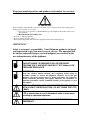
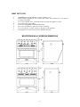
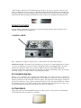
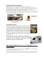
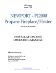
Dickinson Marine
www.dickinsonmarine.com
[email protected]
CARIBBEAN / MEDITERRANEAN
Propane Galley Range
INSTALLATION – USE AND CARE MANUAL
This manual MUST be read carefully
DICKINSON RESERVES THE RIGHT TO CHANGE PRODUCTS OR DOCUMENTS AT ANY TIME
QUALITY INSPECTED BY -
Doug & Don
Form#7.2-23 Issue#1
Sept. 14, 2011
CONTENTS
Warnings and Disclosures
pg - 3
Stove Dimensions
pg - 6
Product Features
pg - 7
Burners and Valves
pg - 09
Fuel Supply Instructions
pg - 10
Fuel Locker Diagram
pg - 11
Fuel System Testing
pg - 12
Gimbaled Instructions
pg - 13
Gimbaled Diagram
pg - 14
Built-In Diagram
pg - 15
Oven Cooking
pg - 18
Care and Cleaning
pg - 18
Troubleshooting
pg - 20
Part Replacements
pg - 20
Limited Warranty
pg - 21
Warranty Form
pg - 22
PACKING LIST
INSTRUCTION MANUAL
SNAP IN GRILL SECTION
POT HOLDER SEARAIL
POT HOLDERS (2)
CUTTING BOARD
OVEN RACK
PROPANE LOCKER & STOVE WARNING PLATE
TIE DOWN BRACKET
2 X 9V BATTERIES
2
WARNING!
THIS IS A LOW PRESSURE
PROPANE GAS APPLIANCE.
YOU MUST HAVE A
SEPARATE 11” W/C
(30 mbar)LOW PRESSURE
REGULATOR INSTALLED
CORRECTLY OR
OPERATION WILL
RESULT IN A
DANGEROUS FIRE AND
WILL DAMAGE YOUR
UNIT.
**PLEASE READ YOUR INSTRUCTION MANUAL
BEFORE USE OF THIS APPLIANCE**
3
Keep your proof of purchase and product serial number for warranty
WARNING:
If the information in this manual is not followed exactly, a fire or explosion may result causing property
damage, personal injury, or loss of life.
— Do not store or use gasoline or other flammable vapors and liquids in the vicinity of this or any
other appliance.
— WHAT TO DO IF YOU SMELL GAS
• Do not try to light any appliance.
• Do not touch any electrical switch..
• Shut off main supply tank, and call the fire department if the boat has filled with gas.
IMPORTANT
Safety is everyone’s responsibility. Your Dickinson product is designed
and constructed to give you many years of safe use. The operation will
be further enhanced if proper care and judgment are exercised in the
use and maintenance of the appliance.
THIS APPLIANCE IS DESIGNED FOR LOW PRESSURE
PROPANE ONLY, AND MUST HAVE AN 11”WC (30mbar) LOW
PRESSURE REGULATOR
IMPORTANT:
Read this owner’s manual carefully and completely before trying to
assemble, operate, or service this appliance. Improper use of this gas
appliance can cause serious injury or death from burns, fire, explosion,
carbon monoxide poisoning and oxygen depletion. For assistance or
additional information consult a qualified installer, service agency, or your
gas supplier.
TEST ALL PROPANE LINES AND CONNECTIONS FOR LEAKS
WITH A SOAPY WATER SOLUTION. DO NOT FLAME TEST FOR
LEAKS.
LPG is heavier than air and if allowed will settle in lower areas
resulting in a potential explosion.
CLOSE THE LPG CYLINDER VALVE IN THE EVENT OF AN
EMERGENCY
4
WARNING:
• DO NOT install this appliance in spaces containing internal combustion engines,
their fuel tanks, or joints and fittings of their fuel systems.
•
•
USE ONLY approved materials, hose, regulators and fittings to install.
10ft Hose – ULC Type I CGA St 8.1 – Dickinson Prt# 19-100-10
20ft Hose – ULC Type I CGA St 8.1 – Dickinson Prt# 19-100-20
Propane Low Pressure Regulator UL/C.G.A – Dickinson Prt# 19-151
DO NOT store or use gasoline or other flammable vapors and liquids in the
vicinity of this or any other appliance.
•
INSTALLATION must conform with local codes or in the absence of codes, with
current National Fuel Gas Code, ANSI Z223.1 or current CAN/CGA B149,
Installation Codes.
•
MANUFACTURED OR MOBILE HOME OEM installation must conform to
Manufactured Home Construction and Safety Standard, Title 24 CFR, Part 3280,
or, when not applicable, the Standard for Fire Safety Criteria for Manufactured
Home Installation Sites and Communities, ANSI/NFPA 501A,(USA) or Mobile
Homes Standard, CAN/CSA-Z240 MH Series, in Canada
•
MAIN GAS VALVE must be disconnected from gas supply system during any
pressure test of the system at pressures greater than ½ psi (3.5 kPa)
IMPORTANT:
Save this manual for future reference.
WHAT TO DO
1.
2.
3.
4.
5.
6.
7.
8.
9.
10.
11.
Begin by ensuring proper installation and verify that the appliance has been connected to 11”
WC low pressure propane.
Be familiar with the location of the gas shut-off.
If you smell gas, do not use the appliance. Immediately turn off the gas supply at the shut-off
valve.
Make sure you have a 3” fresh air vent, or an open window before operating the stove.
Use this appliance only for its intended purpose as described in the manual.
Never let clothing or other flammable materials come in contact with the
burners while in operation.
When cooking, set the burner controls so that the flame heats only the bottom of the pot and
does not lick at the sides of the pot.
Always turn pot handles to the side or back of the appliance. Do not turn handles towards the
front where they are easily hit. Handles should not extend over adjacent burners.
Always check the position of the control knobs to make sure the appliance is off when you are
finished cooking.
Always light each burner prior to placing a pot on the burner grate. Also, turn the control
knob to the “off” position before removing a pot from the burner grate
Wait until the appliance has cooled before cleaning.
Always keep the appliance surface clean and dry.
Affix the Galley Range Warning / Instruction plate by the stove for easy reading.
5
WHAT NOT TO DO
1.
2.
3.
4.
5.
6.
7.
8.
DANGER-Never use the appliance to warm or heat the room.
When using the appliance do not touch the grate, burner caps, burner bases or any parts in
proximity to the flame.
Do not leave children alone or unattended in the area where the appliance is in use.
Do not use water on grease fires.
Never leave the appliance unattended when in use.
Do not use oversized pots or pans. See section on ‘burners’.
Do not use abrasive or caustic cleaners or detergents on this appliance.
Keep appliance area clear and free from combustible material.
MEDITERRANEAN & CARIBBEAN DIMENSIONS
6
* Tie Down Bar – This is the 1/8th aluminum piece that is appox. 10” long *see pic below. The tie down
bar is to be fastened in your stoves cut out so that the bottom panel housing the battery boxes will slide into
it thus preventing your stove from tilting forward as the boat lists. The two screws in the front of this panel
will prevent the unit from sliding forward but will not prevent the stove from tilting and bending the plate.
PRODUCT FEATURES
Your two-burner or three-burner propane stove contains many unique features. Please read this section
carefully as it identifies the most important.
COOKING GRATE
The cooking grate is designed to snap into place to ensure that it is level and to limit vibration.
IMPORTANT NOTE – The stainless grate and burner tops are exposed to extreme temperatures in a matter
of seconds. In addition, pots are slid over them, and spills introduce foods with high acidity to all of the
surfaces and components. These severe operating conditions will cause an inevitable change in the
appearance of the surfaces and components. Do not place pots directly on the burners as they are not made
to hold the weight, so you must use the cooker with the grate in place.
POT HOLDERS AND RAIL
There is a set of potholders and a potholder rail standard with your appliance. The rail is attached by
inserting the legs into the grate and tightening the brass thumbscrews. The grate can be removed and
turned to position the sea rail at the back or front as required. The potholders are then slipped over this rail
and moved to fit the size of pot or pan by squeezing the end legs so they can slide back and forth. Should
the potholders become loose simply spread the legs a little and they will again become secure. It is
recommended that the potholders be used when any boat motion is anticipated.
CUTTING BOARD
The board is used to provide a flat finished surface at counter top level. It also provides a useful cuttingboard feature that can be used in place or elsewhere.
7
WARNING:
WHEN USING OVEN , REMOVE CUTTING BOARD TO ALLOW PROPER
VENTILATION FOR OVEN BURNER. THE OVEN VENTS THROUGH THE SIDES
OF THE COOKING AREA, AND MUST BE FREE OF OBSTRUCTION.
CUTTING BOARD LEVELLING FEATURE
At the four outside corners of the cooking grate there are small tapped holes. By installing 4 – 8-32 screws
into the tapped holes, with the screw head up, the cutting board can be leveled. It is advisable to tighten the
levelers with a nut on the underside to secure them in place
BURNERS
The top surfaces of the burner caps are porcelain enameled to prevent oxidation (rusting) and to provide an
attractive finish.
Triple Burner
These burners are CGA/AGA approved
FLAME DISPERSION
The burner ring spreads the flame evenly around the burner perimeter. This burner assembly must be
seated properly into the base to produce the desired flame configuration.
FLAME CLEARANCE AND POT SIZES
Space is always at a premium on a boat and the Dickinson Propane Stoves give you the most versatility
and the most powerful burners available in a marine cooktop format. For your safety and for good
maintenance of the appliance, use the appropriate size pots for the right and left burners. On the left, a pot
with a 10 inch base is appropriate. On the right hand side it is best not to use pots or pans with bottoms
greater than 6 inches in diameter.
BURNER SAFETY FLAME-OUT
Thermocouple
Each burner is equipped with a thermo-couple safety sensor. Should the
flame accidentally be extinguished the sensor will automatically turn-off the
gas supply to the burner. In addition, should the burner not ignite on start-up
the gas will not continue to flow to the burner when the control knob is
released.
NOTE: The thermocouple may need to be wiped off occasionally to keep
flame lit.
8
BURNER IGNITER AND IGNITER BOX
The burner igniter is located on each burner and is activated by a battery generator.
(Batteries Included – 2 x 9v) The igniter box is located at the bottom of the appliance, below the oven.
To replace the batteries, you will need to unscrew the two bolts, holding the front panel/door onto the oven.
Once unscrewed, simply open the oven door as usual, except now it will come right off the stove.
Now simply unscrew the large black plastic knob on the battery holder.
These knobs contain 9V batteries. When replacing with new batteries, just make sure the battery leads
faces up in the knob. Positioning (as in positive and negative) doesn’t matter. Just as long as the battery
leads slide in first when replacing the knob onto the box.
Battery must face up,
when replacing.
Igniter / Battery Box
GAS CONTROL VALVES
This appliance is equipped with CGA/AGA approved quality gas valves that
offer both electronic ignition and thermocouple flameout safety features. These
valves have been calibrated for use with the burners to produce the required BTU
heat output and flame quality at all settings. The low heat settings on the cooktop
burners are adjustable by removing the knob from the gas valve and placing a
very small flat head screw driver down the center of the shaft. A quarter turn in
either direction will raise or lower the flames in the low position only. (The low
heat settings on the oven control burners are adjustable by removing the knob
from the gas valve and placing a very small flat head screw driver down the shaft
off to the right. A quarter turn in either direction will raise or lower the flames in
the low position only.)
NOTE: The gas valves may seize if they are not used for
a long period of time in the harsh marine environment.
For this reason it is advisable to rotate the gas valves
periodically, a few times over this period.
THE STOVE OPERATES ONLY ON LOW PRESSURE LPG GAS
(11"w/c)(30mbar)
It is recommended that this appliance have a dedicated gas line and
installed. (11” WC)(30mbar) (Dickinson Part No 19-151)
must have a low-pressure regulator
Connect the gas line to the 3/8" flare connector of the cook top with copper or an approved hose. During
this procedure some particles may get into the fuel line. These could block or restrict the burner orifices.
9
BLOW OUT FUEL LINE PRIOR TO ATTACHING TO THE PROPANE SUPPLY AND THE
APPLIANCE OR TAPE OVER THE FITTING WHEN INSTALLING THE FUEL LINE SO NO
DEBRIS WILL ENTER.
LPG System Installation
**In some cases the solenoid valve is installed on the low pressure side of the system (i.e. after the
LPG regulator) See solenoid manufactures’ instruction for proper installation.
1.
2.
3.
4.
Starting from the propane tank itself, the fuel line attachments should occupy the following
positions: (a) the tank shut-off valve, (b) the solenoid valve, (c) the pressure gauge, (d) the
regulator, and (e) the range itself.
If you’ve chosen the gimbaled installation option, the gas supply line should be a flexible fireresistant hose, UL/CGA approved for use with propane systems, 3/8” 10mm forged female flare
nut machine crimped on each end.
If your range is a built-in style, you should use either soft copper tubing or a UL/CGA approved
gas hose with a 3/8” (10mm) forged female flare nuts machine crimped onto each end.
Because every connection is a potential leak, the fuel line should be one continuous length of hose
or tubing. Do not make a “T” off the fuel line between an existing appliance and the gas cylinder
to feed another appliance. (You may install a “T” only within the fuel tanks enclosure (propane
locker).
Be sure not to kink the hose or piping connecting the regulator with the range by bending it too
sharply during installation – remember that the pressure (North American) on the downstream side
of the regulator is less than 0.433 psi (28mbar)
Protect the hose against vibration and damage by securing it tightly to bulkheads and hull side
with non-corrosive ties or clamps which will not cut, abrade or pinch it.
Fuel lines must be protected by close-fitting grommets and sealants where they pass through decks
or bulkheads, and the passage must be made vapor-tight. They should be installed so that they are
readily accessible to inspection.
TYPICAL LPG ON-BOARD SYSTEM
10
WARNING:
• DO NOT install this appliance in spaces containing internal combustion engines, their fuel tanks,
or joints and fittings of their fuel systems.
•
•
USE ONLY approved materials, hose, regulators and fittings to install.
10ft Hose – ULC Type I CGA St 8.1 – Dickinson Prt# 19-100-10
20ft Hose – ULC Type I CGA St 8.1 – Dickinson Prt# 19-100-20
Propane Low Pressure Regulator UL/C.G.A – Dickinson Prt# 19-151
DO NOT store or use gasoline or other flammable vapors and liquids in the vicinity of this or any
other appliance.
•
INSTALLATION must conform with local codes or in the absence of codes, with current National
Fuel Gas Code, ANSI Z223.1 or current CAN/CGA B149, Installation Codes.
•
MANUFACTURED OR MOBILE HOME OEM installation must conform to Manufactured
Home Construction and Safety Standard, Title 24 CFR, Part 3280, or, when not applicable, the
Standard for Fire Safety Criteria for Manufactured Home Installation Sites and Communities,
ANSI/NFPA 501A,(USA) or Mobile Homes Standard, CAN/CSA-Z240 MH Series, in Canada
•
MAIN GAS VALVE must be disconnected from gas supply system during any pressure test of the
system at pressures greater than ½ psi (3.5 kPa)
AFTER GAS HOOK-UP AND BEFORE LIGHTING THE APPLIANCE
TEST ALL GAS CONNECTIONS FOR LEAKS WITH A SOAP SOLUTION
Fuel System Testing
Test your fuel system for leaks each time the cylinder supply valves are opened for appliance use.
Use the following procedure for the test. First, close all range burner valves by turning the controls to
the off position. Next, open the manual cylinder and solenoid valves and make a note of the reading
on the pressure gauge. Now close the manual cylinder valve. The pressure should remain constant for
at least 10 minutes. If it does not, gas is leaking out of the system.
The leaks should be located by applying a mixture of liquid, detergent and water, to ALL connections
and other suspect points. What you’re looking for is bubbles in the solution. This indicates a leak in
the system. Do not attempt to locate leaks using an open flame. Repair and re-test the system
before putting it into operation.
11
Installation Guidelines
Galley Range Installation – General Installation + Safety Guidelines
1.
2.
3.
4.
5.
6.
7.
8.
9.
Before installing your range, fill out the Warranty Registration Form that is printed on the last
page of this manual and send it back to Dickinson Marine, within 10 days of purchase. Keep
your model and serial numbers handy, as they will be required when ordering parts, or
requesting assistance.
Do not locate cabinet storage units or any combustible surfaces at any point directly above the
range.
Dickinson recommends a 30” (75cm) clearance between the range top and any unprotected
combustible cabin top or bulkhead. This clearance may be reduced to 20” (50cm) if the overhead
combustible surface is shielded with at least ¼” (6mm) thick flame retardant millboard topped
with not less than No .28 MSG Sheet metal, 0.015” stainless steel, 0.024” Aluminum, or 0.020”
thick copper.
Gas consumes oxygen in the process of combustion. For this reason it is essential to ventilate the
area in which you plan to use your Propane Stove. We recommend that at least nine square inches
of fresh air ventilation be provided in the vicinity of the range.
Your propane stove is equipped with a thermocouple device that will automatically turn off the
gas supply within 15 seconds to any burner that might accidentally be extinguished. Dickinson
specifically warns that your range should not be used as a cabin or space heater.
The snap in burner grill and frame structure at the top of your range will become very hot during
operation of the range top burners.
The whole range (including the oven door) becomes hot when the oven is being operated. The top
portion of the back of the range becomes extremely hot during operation. Do not contact it with
unprotected skin.
Always keep a Class ABC fire extinguisher mounted close to your Propane Stove. Grease fires
should be extinguished by smothering them with baking soda, or by using the ABC Class fire
extinguisher.
A heat diffusion plate is vital to the operation of the oven. You will find it inside the oven
fastened to an oven rack.
Gimbaled Installation
1.
It is important that the following minimum clearances from combustible materials be adhered to
when installing your gimbaled range.
2 BURNER MODEL: Side – 7” minimum as measured from the center line of the closest burner head.
Rear – 9” minimum as measured from the center line of the closest burner head. Top – 24” minimum
to overhead cabinets, shelves or any other combustible material.
3 BURNER MODEL: Side – 5 1/2” minimum as measured from the center line of the closest burner
head. Rear – 7” minimum as measured from the center line of the closest burner head. Top – 24”
minimum to overhead cabinets, shelves or any other combustible material.
2.
Make a cardboard template the same size as the side view of the range. Punch a hole at the gimbal
location the size of the gimbal, and swing the appliance template in the appliance cut-out location
in the boat on your finger. By allowing a swing of approximately 15” to 20” before interference
12
3.
4.
with the hull or boat structure, the gimbal point can be located. Mark the point. Make certain that
after the gimbal point is determined that the installation matches or exceeds the minimum
clearance in gimbal cutout diagram. It is important that the oven vent be completely clear so the
cutting board must be removed when using the oven.
Locate the companion pieces to the gimbals and install the appliance.
For safety, Dickinson gimbaled appliances are designed with a sliding bolt type lock. The sliding
bolt should lock into an adjacent cabinet or bulkhead to prevent the appliance from swinging in
rough weather.
Caution: The appliance center of gravity will also shift from the gimbal location when the pots are not
balanced on the appliance or when the appliance door is open.
5.
Connect the LPG fuel supply hose fitting to the brass fitting on the appliance manifold and on the
regulation system. Wrench-tighten the fitting to the connection on the appliance. DO NOT use
pipe dope or Teflon tape.
6. Check all gas connections for possible leaks. Turn the valves on your range to their “OFF”
position. Open valve on gas supply tank, then using a strong, soap and water solution, check each
gas connection one at a time by brushing the solution over the connection. Presence of bubbles
will indicate a leak. Tighten the fitting and recheck for leaks
DO NOT USE AN OPEN FLAME FOR CHECKING GAS LEAKS
7. Light the burner for testing.
8. The appliance is now ready for use. Sometimes the burners will not ignite immediately and seem
to “blow” slightly when they do ignite. This is usually due to the presence of air in the gas lines,
which will clear itself, within seconds.
13
Cut-Out Dimension Diagram
Optional Gimbaled Installation
The Gimbal kit is an option we offer, that allows your stove to swing freely,
which keeps it level when you’re on a keel. (i.e sailboat)
Note: The stove can be locked into place, and should be if you aren’t using the
stove, and/or are expecting really rough weather.
See Kit Instructions #26-003
14
Cut-Out Dimension Diagram
Optional Built-In Look ( Trim Kit ) Bracket Installation
See Kit Instructions
Caribbean
Mediterranean
15
2 Burner Model
3 Burner Model
# 26-000
# 26-001
OPERATING YOUR PROPANE STOVE
1.
It is recommended that every time the LPG tank valve is opened for use, the operator close the
valve and watch that the gauge needle remains constant.
2. If leaks occur, correct them. If leaks cannot be corrected, do not operate appliance.
3. Always test light a top burner after operating the tank valve to dispose of air in the supply line.
This could be caused by someone’s opening the system to fill a LPG tank or by opening a burner
valve.
4. In an emergency, close the LPG tank valve immediately.
5. The pressure gauge on the LPG regulation system is only a leak detector. The gauge does not
indicate how much LPG fuel is in the tank.
6. Before removing an empty or near empty tank for refilling..
a. IMPORTANT Always close the LPG tank valve.
b. With the tank valve closed, remove the left-hand threaded nut connecting to the
regulation system
c. Reconnect the regulation system. Left hand thread. Do not use Teflon tape or pipe dope.
7. When transporting an LPG tank, always be aware that the tank valve has a built-in relief. In that it
could open and allow LPG fuel to escape in automobile, storage area – anywhere.
8. When the appliance is not being used, always close the main gas valve on the LPG tank supplying
fuel to the appliance
IT’S ALWAYS GOOD TO HAVE AN ABC TYPE FIRE EXTINGUISHER IN THE GALLEY AREA
Lighting the Range Top Burners
LIGHTING THE BURNERS
WARNING :
BEFORE LIGHTING BURNERS REMOVE ALL FLAMMABLE MATERIALS
E.G. CURTAINS, TOWELS ETC. FROM THE IMMEDIATE VICINITY.
Ensure burners are properly seated in their base.
Each knob controls a different valve. To light the burner, press down on the knob to activate the electronic
ignition. Rotate the knob counter clockwise until the white line is level with the high setting. The burner
will then light with the flame at the high setting. Continue to rotate counter clockwise to select lower flame
settings.
The igniters on all burners will spark continuously until the gas ignites on the selected burner.
Ignition should occur within four seconds of turning to this position. The igniters will stop sparking as
soon as the knob is released.
IMPORTANT: When the stove is first installed, the surface burners may be difficult to light due to air in
the gas line. This may occur if the appliance has been disconnected from the main gas supply, or if it has
not been used in several weeks or months.
1.
2.
3.
4.
5.
6.
7.
8.
Before lighting, please ensure burner caps are placed on burners.
Read and comply with all gas safety instruction per this manual.
Turn all control knobs to the OFF position
Open the manual cylinder and solenoid valves. (Turn the manual cylinder valve in a
counterclockwise direction, and switch the solenoid valve to the high position)
Push control knob as far as it will go and turn it counterclockwise to the HIGH position until
burner is lit.
Sometimes the burner will sputter for a while before igniting. Give your range 10-15 seconds to
purge the air out of the gas line.
Continue holding the burner control knob all the way in for about five seconds after ignition. This
will heat the thermocouple and allow the gas valve to stay open. The thermocouple is designed to
cut off the gas supply to burner if the flame should accidentally be extinguished somehow.
This arrangement also ensures that the range is childproof, to the extent that a simple twisting of
the control knobs, will not light any burners or allow gas to enter your boat.
16
9.
10.
11.
12.
13.
14.
15.
16.
Do not touch any burner cap, burner base or igniter while igniters are sparking as an electrical
shock could result.
The flame should be steady and blue in color. Foreign material in the gas line, especially in new
installations, may cause an orange flame during initial operation. This will disappear with further
use.
The flame should burn evenly around the perimeter of the burner. If the flame is uneven ensure
that the burner covers are properly positioned.
If the burner does not ignite within four seconds, then turn off the valve. Allow at least a minute
for any gas to dissipate, and then repeat the lighting process.
You should now be able to set the flame to any desired level between High and Low by turning
the control knob in the appropriate direction.
To turn off the burner, turn the control knob clockwise to the OFF position.
You must shut off both the solenoid and the manual gas cylinder valves whenever your vessel is
unattended or if there is an emergency. Dickinson recommends that you also shut the cylinder
valves off whenever your propane stove is not in use.
If a burner does not ignite, consult the Trouble Shooting Guide.
DO NOT LEAVE ANY BURNER ON HIGH FOR EXTENDED PERIODS OF TIME. THE BURNERS
ARE FOR COOKING, AND SHOULD NOT BE USED TO HEAT YOUR BOAT.
NOTE: Wait until the cook top is cool before installing the cutting board or damage will occur to the
board.
Adjusting the flame
Adjust the flames size so it does not extend beyond the end of the pan/utensil
that is on the burner. This is for safety and to prevent possible damage to the
appliance, pan, or cabinets above the appliance.
Lighting the Oven Burner or Broiler
1.
2.
3.
4.
It is essential to the proper operation of your oven that the stainless steel heat diffusion plate is in
place. Unless you’ve taken it out to clean it, it should already be in place.
Read and comply with all gas safety instructions per this manual.
The oven door must be opened first, then push in the control knob; this will start the spark
ignition system. At the same time turn the control knob left, to the desired temperature, hold the
knob down until the burner is lit. Continue holding the burner control knob all the way in for
about 5-6 seconds after ignition. This will heat the thermocouple and allow the gas valve to stay
open. Close the oven door carefully to ensure that the oven burner will not be extinguished.
To light the broiler, follow the above instructions but turn the burner control knob right, instead of
left, and allow more time for the burner to ignite, by holding in the valve a little longer during
sparking.
NOTE: THE CUTTING BOARD SHOULD BE REMOVED WHEN USING THE OVEN, AS THE OVEN “BREATHES”
THROUGH THE TOP OF THE COOKING AREA. THE VENTS MUST NOT BE BLOCKED, FOR CORRECT
OPERATION
Thermostatically controlled oven operation
The burner will operate on high until the set temperature is reached. The burner will then automatically
reduce to a low flame. During operation the burner never goes off.
When the temperature has been reached and the flame is low, be sure to close the oven door slowly when
checking on your food.
17
Oven Cooking Considerations
Aluminum Foil – Do not cover an entire rack with foil or place foil directly under cookware. To catch
spillovers, place a piece of foil a little larger than the pan, on the rack below the pan.
DO NOT PLACE FOIL ON THE OVEN BOTTOM.
Allow hot air to flow freely through the oven for optimum baking results. Improper placement of pans in
the oven will block air flow and will result in uneven browning. For optimum browning and even cooking
results:
• Do not crowd a rack with pans. Never place more than one cookie sheet, one cake pan or two round pans
on the rack.
• Stagger pans when baking on two racks so one pan is not directly over another pan.
• Allow two inches between the pan and the oven walls
Cookware Considerations
The cooking performance is greatly affected by the type of cookware used. Proper cookware will reduce
cooking times, use less energy and produce more even cooking results. For best results use a heavy gauge
metal pan with a smooth flat bottom, straight sides and a tight fitting lid.
Cookware with uneven, warped, or grooved bottoms, do not make good contact with the heating surface
and will reduce heat conductivity and result in slower less even heating.
The pan material determines how evenly and quickly heat is conducted from the heat source to the food.
Some widely used pan materials are.
Aluminum – excellent heat conductor. Some food will cause it to darken or pit. Often used as a bottom
coating to improve the heating of other pan materials.
Copper - excellent heat conductor. Discolors easily, requires constant polishing. Often used as a bottom
coating to improve the heating of other pan materials.
Stainless Steel - slow heat conductor. Develops hot spots, and produces uneven cooking results. Durable,
attractive and easy to clean. Will distribute heat better if other materials are combined or sandwiched
together as a bottom coating.
Cast Iron – Slow heat conductor. Cooks evenly once temperature is reached. Heavy, needs seasoning to
make cleaning easier and to prevent sticking and rusting.
Glass – Slow heat conductor. Easy to clean. Some types may only be used in the oven.
Porcelain Enamel – glass-like substance fused to metal. Heating characteristics depend on base material.
Easy to clean.
CARE AND CLEANING
WARNINGS:
1.
2.
Before cleaning the cook-top, ensure that the burners are turned off and that all components
are cool enough to safely touch.
After cleaning re-assemble all components before attempting to operate the cook-top.
Proper cleaning is necessary to maintain appliance performance and appearance. Wipe up spills that
occur while cooking, but wait for cooker to cool. Spills that remain on hot burner components will be
very difficult to clean, especially if allowed to burn on. Spills of certain foods, such as tomatoes, citrus
juices, vinegar, alcohol and milk are harmful if allowed to stand for any length of time.
18
1.
2.
3.
4.
5.
6.
Do not use any abrasive chemical cleaners on the inside, or outside of your range. Any household
liquid cleaner is recommended.
Use a clean cloth or sponge to apply cleaners.
Remove stains as quickly as possible before they become “set”.
Do not let food spills or burnt foods build up on any surface of your galley range.
You can use a household oven cleaner for the oven, but remember to follow the product
manufacturer’s directions.
Do not use steel wool or SOS-type pads to clean any part of your stove, as these products will
embed fine steel particles in the surface of the stainless steel causing it to bleed in a marine
environment. Use bronze wool or some other nonmetallic abrasive if you must. Be aware, that
your range has a fine finish that can be scratched by some abrasive pads or cleaners.
PROLONGED LAY UP
The Dickinson Propane Stove has been designed to have a long life, with every day use. However, if you
leave your boat unattended for a long period of time, particularly in high heat and humid conditions, or
long winter conditions, the high temperature lubricant in the gas control valves may settle, resulting in
difficulty in turning the control valves and possibly seizure of the valve.
NOTE: As part of preventative maintenance, if you anticipate a prolonged lay-up period for your
stove, it is advisable that you periodically rotate your gas valves from time to time, to prevent
possible valve seizure.
In the event that your valve does seize, it will be best to remove the control panel from the range by first
pulling off the control knobs, then unscrew the acorn nuts and remove the panel. We highly recommend
that you do NOT open and service the gas valve as it is very difficult to re-assemble, ( it may damage
internal parts and / or may leak). With that being said you have a 50/50% chance of fixing or breaking the
valve. Use pliers or vise grips on the brass shaft then PUSH IN and turn counterclockwise ONLY. This will
either loosen the shaft or break it (the shaft will turn but not operate the valve).
NOTE: If you don’t have experience with gas and would like to fix the valve and not take the chance of
breaking it call or better yet email tech support for guidance.
NOTE: Do a soap test on the valve after assembly to ensure there are no leaks.
CLEANING ORIFICE
The orifices of the burners are accessed by removing the 4 screws on the inside walls of the cooking area
and then lift the top off the stove. The large burner cap and body is simply lifted off the burner base
support. This reveals the small hole which is the gas inlet orifice. The small burner cap is unscrewed
counterclockwise. Remove the two small screws on top of the burner base and then lift off the assembly. It
is advisable to unscrew and remove the orifice for cleaning. Cleaning the orifice in place may result in a
repeat blockage soon after re-using the cook-top, however turning the orifice drill clockwise, the twisted
flutes of the drill may remove the debris upwards and out (works 70% of the time). When putting parts
back on, make sure the burner tops are put on before the stove top is reinstalled.
NOTE: When putting the small burner back on, make sure to screw in the screws evenly. Start one
screw off, then start the other, then adjust each one incrementally. If you don’t, the burner will go in
crooked, and you will risk damaging it.
CLEANING THE OVEN HEAT-DISPERSER
1.
2.
3.
Open the oven
Then lift up plate, and pull towards you.
Now you can clean the heat-disperser, by following the same care and
cleaning instructions listed above.
19
TROUBLE – SHOOTING GUIDE
If something should go wrong with the operation of your Propane Stove, do not despair! Read this section
carefully and follow our suggested remedies.
If these suggestions do not resolve the difficulty, please contact your local dealer, or contact us directly, for
more support.
Gas Smell
1.
2.
3.
4.
Extinguish all open flames and smoking materials.
Close both manual and solenoid cylinder valves
Make sure that all appliance valves are closed.
Ventilate all interior compartments thoroughly. Use a fan to push the air from the bottom of all
compartments.
5. Maintaining as much ventilation as possible, open cylinder valves. Making sure the appliance
valves are still closed.
6. When repair of the leaks has been completed, test the system with the aid of the pressure gauge,
using the procedure previously described for Fuel System Testing (Page 14)
Ignition System Fails to Spark or Begins to Spark Slowly
1.
Check the 9V batteries located at the bottom inside right stove side, to ensure it is still supplying
power and installed correctly. Install a new battery if necessary. If none of the spark plugs will
spark after the battery is checked or replaced you may need to order a replacement spark ignition
box from Dickinson.
2. Check to see whether there is 3/32” (2mm) gap between the spark plug head (which should be
clean) and the burner rim, and that all the wires are securely connected to the spark ignition box
located midway down the backside of the stove. A quick way to check is to press any control
knob and look to see if spark is sparking between the terminals.
3. Check the operation of each switch with a circuit tester. Remove control knobs and faceplate and
check the wire connections at the back of the spark ignition switch harness.
4. Sometimes a minor nick in the wire will cause a short so the spark plug will not spark at that
burner. Remove the stove so that each spark ignition connecting wires can be checked for shorts.
Sometimes the burner will sputter for a while before igniting. Give the stove 10-15 seconds to purge
any air out of the gas line.
No gas to burners - Supply tank empty
Igniter does not spark -Replace igniter battery 9V
Shut-off valve closed
- Igniter box replacement
Burner orifice blocked
- Electrode wire shorting
Poor quality flame- Dirt in the fuel line
Cutting Board uneven - Cutting Board Leveling (pg 8)
Partially blocked orifice
Pot Holders are loose - Spread legs by hand
Burner top not installed correctly
Low flame - Supply tank low pressure
Partially blocked orifice
PARTS REPLACEMENTS
•
•
•
•
•
•
•
Hard Wood Cutting boards. 2 burner- #26-010 3 burner -#26-011
Pot Holders #26-020
Gas Control Knob top burners #26-040 oven #26-041
SeaRail #26-021
Gimbal Mount Kit #26-003
Built In Kit 2 burner- #26-000 3 burner- #26-001
Cooking rack 2 burner-# 26-030 3 burner- # 26-031
20
LIMITED WARRANTY
WARRANTY PROVISIONS : dickinson warrants this product to be free of defects in workmanship and materials
for a period of one year. This warranty is limited to claims submitted in writing within a one-year period following the
date of purchase. If any part of your new product fails because of a manufacturing defect within the warranty period
dickinson offers to replace said parts free of charge, provided, however, that such parts have not been improperly
repaired, altered or tampered with or subjected to misuse, abuse or exposed to corrosive conditions. This warranty,
however, is limited by certain exclusions, time limits and exceptions as listed below. Read these limitations and
exclusions carefully.
TIME LIMIT : This warranty is given too and covers only the original purchaser. Coverage terminates one year from
the date of purchase for parts replacement.
EXCLUSIONS : This warranty does not cover or include : (a) Any normal deterioration of the product and appearance
of items, due to wear and/or exposure; (b) any guarantees, promises, representations, warranties or service agreements
given or made by an authorized distributor or other person selling this product, other than those specifically stated
herein; (c) any damage or defect due to accident, improper repair, alteration, unreasonable use including failure to
provide reasonable and necessary maintenance, misuse or abuse of the equipment, or exposure to corrosive conditions.
This warranty is conditioned upon normal use, reasonable and necessary maintenance and service of your product, and
written notice being given promptly upon Buyer's discovery of a warranty claim, pursuant to paragraph 6 below.
Reasonable and necessary maintenance is maintenance which you are expected to do yourself or have done for you. It
is maintenance, which is necessary to keep your product performing its intended function and operating at a reasonable
level of performance.
DAMAGE LIMITATION WARNING : IN NO EVENT SHALL dickinson BE LIABLE FOR ANY INCIDENTAL
OR CONSEQUENTIAL DAMAGES, INCLUDING (BUT NOT LIMITED TO) LOSS OF USE OF THE PRODUCT,
LOSS OF TIME, INCONVENIENCE, EXPENSES FOR TRAVEL, LODGING TRANSPORTATION CHARGES,
LOSS BY DAMAGE TO PERSONAL PROPERTY OR LOSS OF INCOME, PROFITS OR REVENUE.
ORAL OR IMPLIED WARRANTY LIMITATIONS : The foregoing warranty is exclusive and in lieu of all other
warranties, written or oral, expressed or implied, including but not limited to any warranty or merchantability or fitness
for a particular purpose.
TRANSFER LIMITATIONS : This warranty is not assignable or transferable. It covers only the original purchaser
.
CLAIM PROCEDURE : In the event of a defect, problem or that a breach of this warranty is discovered, in order to
protect any warranty rights you must promptly notify Dickinson. Give name, address, and model name, location of
unit, description of problem and where you can be reached during business hours.
RESERVED RIGHT TO CHANGE : Dickinson reserves the right to make changes or improvements to products it
produces in the future without imposing on itself any obligations to install the same improvements in the products it has
previously manufactured.
SECOND OR SUBSEQUENT OWNER : Dickinson does not give any warranty to secondary or subsequent
purchasers, and it disclaims all implied warranties to such owners.
INSPECTION : To assist you in avoiding problems with your product and to validate this warranty you are required to
do the following : (a) read the warranty; (b) inspect the product. Do not accept delivery until you have examined the
product with your supplier; (c) ask questions about anything you do not understand concerning the product.
OWNER REGISTRATION : Fill out the WARRANTY CARD within 30 days from the date of delivery.
WARRANTY : RETURN OF THE CARD IS CONDITION PRECEDENT TO WARRANTY COVERAGE
AND PERFORMANCE. IF YOU DO NOT FILL OUT AND MAIL THE CARD AS DIRECTED, YOU WILL
NOT HAVE A WARRANTY.
LEGAL RIGHTS : This warranty gives you specific legal rights and you may also have other rights, which may vary
within different government jurisdictions.
21
Return to:
SINCE 1932
#101-17728 66 Ave, Surrey, B.C. Canada V3S 7X1
WARRANTY FORM
I have read and understand the Limited Warranty and the Instruction Manual
and agree to the terms and conditions
(please print)
Date……………………………………………………………………………
Purchaser’s Name……………………………………………………………..
Address………………………………………………………………………..
………………………………………………………………………………...
…………………………………………………………………………………
Model Name……………………………………………………………………
Serial Number…………………………………………………………………
Date Of Purchase……………………………………………………………..
Signature……………………………………………………………………..
Name of Seller…………………………………………………………….....
Seller Location………………………………………………………………
Note: The warranty form can be filled out and sent from the
website: www.dickinsonmarine.com
22