1
1
2
3
4
5
6
7
Bayer Corporation Blood Glucose Meter
8
9
Computer Interface Specification
10
11
November 21, 2006
12
13
Part No. 99993952
14
15
Revision C
16
17
18
19
20
21
22
23
24
25
26
27
Questions on this document should be referred to:
Bayer HealthCare LLC
Technical Customer Services
Mishawaka, IN 46544 USA
In USA,
Telephone: 1-800-348-8100 prompt 1, then 2
28
© Copyright 2000-2006 Bayer HealthCare, Diabetes Care
Bayer Corporation Blood Glucose Meter
Computer Interface Specification
Part Number:
99993952, Rev. C
Page 2 of 98
Date: 11/21/06
1
2
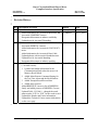
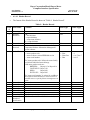
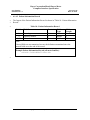
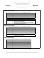
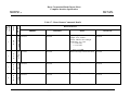
Revision History:
3
4
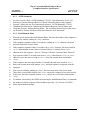
Rev Description of Change
Initial release
A
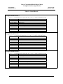
- Added information for Ascensia® BREEZE® and
Ascensia® CONFIRM™ meters.
- Reorganized document to enhance readability.
- Updated text for Ascensia™ branding.
B
- Revised information for Ascensia® DEX® 2 and
Ascensia® ESPRIT® 2 meters.
- Added information for Ascensia® CONTOUR™
meter.
- Added information for Ascensia® Data Cable.
- Updated photos with Ascensia® branded meters.
- Updated text for Ascensia® branding.
- Reorganized document to enhance usability.
C
- Added information for Ascensia® CONTOUR™
(5-second version):
1. Updated and added information for the
Communication Mode when the meter is in
Memory Recall Mode.
2. Added Meter Remote Command Setting for
the Test Time Alarm and the Meal Markers.
3. Added Example Result Record data.
4. Added meter pictures.
- Added BREEZE® 2 meter to list of BREEZE®
family and added pictures of BREEZE® 2 meter.
- Updated Table 12: Filed 9 – changed the result
status marker “E/D” to “E\D” for the result record.
- Updated the Header and Footer information.
- Updated the Technical Center contact information
on the cover page.
Author
J. Perry
G. Johnson
Nov 1, 2002
G. Johnson
Sep 5, 2003
Kevin Chang
Nov 21, 2006
5
© Copyright 2000-2006 Bayer HealthCare, Diabetes Care
Date
Bayer Corporation Blood Glucose Meter
Computer Interface Specification
Part Number:
99993952, Rev. C
Page 3 of 98
Date: 11/21/06
1
Table of Contents
2
REVISION HISTORY: ............................................................................................................................... 2
3
1.0
SCOPE ............................................................................................................................................ 7
4
2.0
REFERENCED DOCUMENTS ................................................................................................... 8
5
3.0
METER OPERATING MODES .................................................................................................. 9
6
3.1
BREEZE® Meter Operating Modes .......................................................................................... 10
7
8
9
10
11
3.1.1
3.1.2
3.1.3
3.1.4
3.1.5
BREEZE® Meter in Test Mode .................................................................................................. 11
BREEZE® Meter in My Setup Mode .......................................................................................... 11
BREEZE® Meter in My Results Mode ....................................................................................... 11
BREEZE® Meter in Home Mode ............................................................................................... 12
BREEZE® Meter in Data Transfer Mode/Remote Command Mode.......................................... 13
12
3.2
13
14
15
16
3.2.1
3.2.2
3.2.3
3.2.4
17
3.3
18
19
3.3.1
3.3.2
20
3.4
21
22
23
24
3.4.1
3.4.2
3.4.3
3.4.4
25
4.0
PHYSICAL/ELECTRICAL INTERFACE AND CONNECTION ......................................... 27
26
4.1
EIA-232 Based Interface ............................................................................................................. 27
27
4.1.1
28
4.2
29
30
31
4.2.1
4.2.2
4.2.3
32
5.0
ASCII CONTROL CHARACTER NOTATION ...................................................................... 38
33
6.0
COMMUNICATION OVERVIEW ........................................................................................... 39
34
6.1
Data Transfer Mode...................................................................................................................... 39
35
36
6.1.1
6.1.2
CONTOUR™ Meter Operating Modes ..................................................................................... 15
CONTOUR™ Meter in Test Mode ............................................................................................. 16
CONTOUR™ Meter in Setup Mode ........................................................................................... 16
CONTOUR™ Meter in Memory Recall Mode ........................................................................... 17
CONTOUR™ Meter in Communication Mode .......................................................................... 18
DEX® Meter Operating Modes .................................................................................................. 20
DEX® Meter in Testing Mode .................................................................................................... 21
DEX® Meter in Features Mode.................................................................................................. 22
ELITE™ XL Meter Operating Modes....................................................................................... 23
ELITE™ XL Meter in Testing Mode .......................................................................................... 24
ELITE™ XL Meter in Setup Mode............................................................................................. 25
ELITE™ XL Meter in Memory Recall Mode ............................................................................. 25
ELITE™ XL Meter in Communications Mode........................................................................... 26
EIA-232 Variants ........................................................................................................................ 28
Serial Interface Cables................................................................................................................. 29
Ascensia® Data Cable................................................................................................................. 31
Glucometer® DEX® Data Cable ................................................................................................ 34
Glucometer ELITE® XL Data Cable.......................................................................................... 36
ASTM Standards......................................................................................................................... 41
Establishment Phase.................................................................................................................... 41
© Copyright 2000-2006 Bayer HealthCare, Diabetes Care
Bayer Corporation Blood Glucose Meter
Computer Interface Specification
Part Number:
99993952, Rev. C
Page 4 of 98
Date: 11/21/06
1
2
3
4
5
6
7
8
9
10
6.1.3
6.1.3.1
6.1.3.2
6.1.3.3
6.1.4
6.1.4.1
6.1.4.2
6.1.4.3
6.1.4.4
6.1.4.5
ASTM E-1381 Frames ................................................................................................................ 42
Frame Structure ........................................................................................................................... 42
Frame Checksum......................................................................................................................... 43
Defective Frames......................................................................................................................... 43
ASTM E-1394 Records............................................................................................................... 44
Header Record............................................................................................................................. 45
Patient Information Record ......................................................................................................... 49
Test Order Record ....................................................................................................................... 50
Result Record .............................................................................................................................. 51
Message Terminator Record ....................................................................................................... 65
11
6.2
12
13
14
15
16
17
18
19
20
21
22
23
6.2.1
6.2.2
6.2.3
6.2.3.1
6.2.3.2
6.2.3.3
6.2.3.4
6.2.3.5
6.2.3.6
6.2.3.7
6.2.3.8
6.2.3.9
24
6.3
DEX® Meter Smart Modem Dialing.......................................................................................... 81
25
6.4
Example Communication Sequences.......................................................................................... 84
26
27
28
29
30
31
32
33
34
6.4.1
6.4.2
6.4.3
6.4.4
6.4.5
6.4.6
6.4.7
6.4.8
6.4.9
35
7.0
DATA COMMUNICATION HINTS ......................................................................................... 97
36
7.1
Determine Presence of Meter ...................................................................................................... 97
37
7.2
Determine Which Meter is Connected ....................................................................................... 97
38
7.3
Configure Meter without Receiving Test Results...................................................................... 98
Remote Command Mode Protocol ............................................................................................... 66
Initiating Remote Command Mode.............................................................................................. 67
Terminating Remote Command Mode......................................................................................... 67
Remote Commands ..................................................................................................................... 67
Remote Command Format .......................................................................................................... 67
Remote Command Protocol and Error Checking........................................................................ 68
Remote Command Response....................................................................................................... 69
Remote Command Details........................................................................................................... 69
Remote Command Considerations .............................................................................................. 70
BREEZE® Meter Remote Command Examples......................................................................... 76
CONTOUR™ Meter Remote Command Examples.................................................................... 77
DEX® Meter Remote Command Examples................................................................................ 78
ELITE™ XL Meter Remote Command Examples .................................................................... 80
BREEZE® Meter Send Results and Receive Configuration....................................................... 84
CONTOUR™ Meter Send Results and Receive Configuration ................................................. 85
DEX® Meter Send Results and Receive Configuration ............................................................. 86
ELITE™ XL Meter Send Results and Receive Configuration .................................................. 87
BREEZE® Meter Communication Example with Framing ........................................................ 88
CONTOUR™ Meter Communication Example with Framing................................................... 90
DEX® Meter Communication Example with Framing............................................................... 92
ELITE® XL Meter Communication Example with Framing...................................................... 94
DEX® Meter Send Results Including Frames with Attached Modem........................................ 96
39
© Copyright 2000-2006 Bayer HealthCare, Diabetes Care
Bayer Corporation Blood Glucose Meter
Computer Interface Specification
Part Number:
99993952, Rev. C
Page 5 of 98
Date: 11/21/06
1
List of Figures
2
FIGURE 1: BREEZE® METER OFF .............................................................................................................. 10
3
FIGURE 2: BREEZE® 2 METER OFF............................................................................................................ 10
4
FIGURE 3: BREEZE® METER IN TEST MODE............................................................................................... 11
5
FIGURE 4: BREEZE® METER IN HOME MODE ............................................................................................ 12
6
FIGURE 5: BREEZE® METER DATA TRANSFER MODE/REMOTE COMMAND MODE DISPLAYS ....................... 13
7
FIGURE 6: BREEZE® METER IN DATA TRANSFER MODE ............................................................................. 14
8
FIGURE 7: CONTOUR™ METER OFF ......................................................................................................... 15
9
FIGURE 8: CONTOUR™ METER (15-SECOND VERSION) IN TEST MODE...................................................... 16
10
FIGURE 10: CONTOUR™ METERS IN MEMORY RECALL MODE................................................................... 17
11
FIGURE 12: CONTOUR™ METER COMMUNICATION MODE DISPLAYS ......................................................... 19
12
FIGURE 13: CONTOUR™ METERS IN COMMUNICATION MODE .................................................................. 19
13
FIGURE 14: DEX® METER OFF ................................................................................................................... 20
14
FIGURE 15: DEX® METER IN TESTING MODE .............................................................................................. 21
15
FIGURE 16: DEX® METER IN FEATURES MODE ........................................................................................... 22
16
FIGURE 17: ELITE™ XL METER OFF ......................................................................................................... 23
17
FIGURE 18: ELITE™ XL METER IN TESTING MODE .................................................................................... 24
18
FIGURE 19: ELITE™ XL METER IN MEMORY RECALL MODE ...................................................................... 25
19
FIGURE 20: ELITE™ XL METER IN COMMUNICATIONS MODE .................................................................... 26
20
FIGURE 21: ASCENSIA® DATA CABLE ILLUSTRATION ................................................................................. 31
21
FIGURE 22: ASCENSIA® DATA CABLE CONNECTOR DIAGRAMS .................................................................. 32
22
FIGURE 23: ASCENSIA® DATA CABLE CONNECTOR PINOUT ....................................................................... 32
23
FIGURE 24: ASCENSIA® DATA CABLE ADAPTER (OPTIONAL, USER-SUPPLIED) .......................................... 33
24
FIGURE 25: GLUCOMETER® DEX® DATA CABLE AND ADAPTER ILLUSTRATION ....................................... 34
25
FIGURE 26: GLUCOMETER® DEX® METER COMPUTER INTERFACE CABLE CONNECTOR DIAGRAM .......... 35
26
FIGURE 27: GLUCOMETER® DEX® METER COMPUTER INTERFACE CABLE ADAPTER DIAGRAM ............... 35
27
FIGURE 28: GLUCOMETER ELITE® XL DATA CABLE AND ADAPTER ILLUSTRATION ................................. 36
28
FIGURE 29: GLUCOMETER ELITE® XL DATA CABLE CONNECTOR DIAGRAMS .......................................... 37
29
30
FIGURE 30: GLUCOMETER ELITE® XL DATA CABLE ADAPTER DIAGRAM ................................................ 37
© Copyright 2000-2006 Bayer HealthCare, Diabetes Care
Bayer Corporation Blood Glucose Meter
Computer Interface Specification
Part Number:
99993952, Rev. C
Page 6 of 98
Date: 11/21/06
1
2
List of Tables
3
TABLE 1: BAYER CORPORATION BLOOD GLUCOSE METER FAMILIES ............................................................ 7
4
TABLE 2: METER OPERATING MODE AND CAPABILITY SUMMARY ................................................................ 9
5
TABLE 3: METER SERIAL INTERFACE PHYSICAL AND ELECTRICAL CHARACTERISTICS ................................ 27
6
TABLE 4: EIA-232 VARIANTS DESCRIPTIONS .............................................................................................. 28
7
TABLE 5: SERIAL INTERFACE CABLE CHARACTERISTICS AND COMPATIBILITY............................................ 30
8
TABLE 6: ASCII CONTROL CHARACTERS .................................................................................................... 38
9
TABLE 7: DATA TRANSFER MODE SUMMARY ................................................................................................ 40
10
TABLE 8: ASTM E-1381 FRAME STRUCTURES ............................................................................................ 42
11
TABLE 9: HEADER RECORD ......................................................................................................................... 45
12
TABLE 10: PATIENT INFORMATION RECORD ................................................................................................ 49
13
TABLE 11: TEST ORDER RECORD ................................................................................................................. 50
14
TABLE 12: RESULT RECORD ........................................................................................................................ 51
15
TABLE 13: MESSAGE TERMINATOR RECORD ............................................................................................... 65
16
TABLE 14: REMOTE COMMAND MODE SUMMARY ....................................................................................... 66
17
TABLE 15: REMOTE COMMAND FORMATS ................................................................................................... 68
18
TABLE 16: REMOTE COMMAND RESPONSE FORMATS .................................................................................. 69
19
TABLE 17: METER REMOTE COMMANDS DETAILS ....................................................................................... 71
20
TABLE 18: BREEZE® METER REMOTE COMMAND EXAMPLES ................................................................... 76
21
TABLE 19: CONTOUR™ METER REMOTE COMMAND EXAMPLES.............................................................. 77
22
TABLE 20: DEX® METER REMOTE COMMAND EXAMPLES.......................................................................... 78
23
TABLE 21: ELITE™ XL METER REMOTE COMMAND EXAMPLES ............................................................... 80
24
TABLE 22: MODEM COMMANDS ................................................................................................................... 81
25
26
TABLE 23: MODEM RESPONSES .................................................................................................................... 82
© Copyright 2000-2006 Bayer HealthCare, Diabetes Care
Bayer Corporation Blood Glucose Meter
Computer Interface Specification
Part Number:
99993952, Rev. C
Page 7 of 98
Date: 11/21/06
1
1.0
2
3
4
5
6
Bayer Corporation produces a variety of blood glucose meters, both with and without a
computer interface. This document describes the computer interface used by all Bayer
Corporation blood glucose meters that have a computer interface. For simplicity, only
Bayer Corporation blood glucose meters that have a computer interface are discussed
within this document.
7
8
9
10
11
All Bayer Corporation blood glucose meters (with a computer interface) are organized
into families within this document. All of the members within each meter family share
an identical computer interface protocol message definition, although the physical and
electrical interfaces vary slightly among and within the Bayer Corporation Blood
Glucose meter families.
12
13
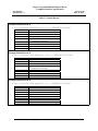
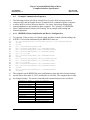
The meter families and family members are defined in "Table 1: Bayer Corporation
Blood Glucose Meter Families".
14
Scope
Table 1: Bayer Corporation Blood Glucose Meter Families
Meter
Family
Meters Contained in Class
Ascensia® BREEZE®
BREEZE®
Ascensia® BREEZE® 2
Ascensia® CONFIRM®
Ascensia® CONTOUR™
CONTOUR™ (15-second and 5-second
versions)
Glucometer® DEX®
Glucometer® DEX® 2
Ascensia® DEX® 2
Glucometer® ESPRIT®
DEX®
Glucometer® ESPRIT® 2
Ascensia® ESPRIT® 2
Glucometer® Dexter-Z®
Ascensia® DEXTER–Z® II
Glucometer ELITE® XL
ELITE® XL
Ascensia ELITE® XL
Ascensia ELITE® XLMC
15
© Copyright 2000-2006 Bayer HealthCare, Diabetes Care
Bayer Corporation Blood Glucose Meter
Computer Interface Specification
Part Number:
99993952, Rev. C
1
2
3
Page 8 of 98
Date: 11/21/06
This document is intended to provide technical information in order to facilitate the
writing of computer programs that communicate with Bayer Corporation blood glucose
meters. This document describes:
4
5
6
7
8
9
10
11
12
13
14
15
•
Relevant meter behavior (see "Section 3.0 Meter Operating Modes")
•
The physical/electrical connection to the meter (see "Section 4.0
Physical/Electrical Interface and Connection")
•
The communication protocol for transmitting test results through the computer
interface (see "Section 6.1 Data Transfer Mode")
•
The communication protocol for configuring the meter and interrogating the
meter configuration through the computer interface (see "Section 6.2 Remote
Command Mode Protocol")
•
Example Communication Sequences (see "Section 6.4 Example Communication
Sequences")
•
Data Communication Hints (see "Section 7.0 Data Communication Hints")
16
2.0
Referenced Documents
17
The following documents are referenced in this specification.
ANSI/EIA-232-D-1986
"Interface Between Data Terminal Equipment and Data
Circuit-Terminating Equipment Employing Serial Binary
Data Interchange", Electronic Industries Association,
January 1987.
ANSI X3.4-1986
"Coded Character Sets – 7-Bit American National
Standard Code for Information Interchange (7-Bit
ASCII)", American National Standards Institute, 1986.
ASTM E 1381-95
"Standard Specification for Low-Level Protocol to
Transfer Messages Between Clinical Laboratory
Instruments and Computer Systems", 1997 Annual Book
of ASTM Standards, volume 14.01, American Society
for Testing and Materials, 1997.
ASTM E 1394-91
"Standard Specification for Transferring Information
Between Clinical Instruments and Computer Systems",
1997 Annual Book of ASTM Standards, volume 14.01,
American Society for Testing and Materials, 1997.
18
© Copyright 2000-2006 Bayer HealthCare, Diabetes Care
Bayer Corporation Blood Glucose Meter
Computer Interface Specification
Part Number:
99993952, Rev. C
Page 9 of 98
Date: 11/21/06
1
3.0
Meter Operating Modes
2
3
4
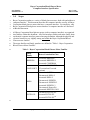
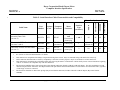
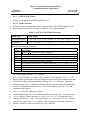
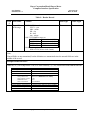
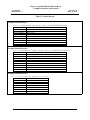
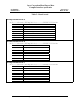
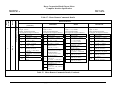
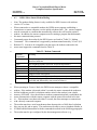
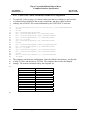
"Table 2: Meter Operating Mode and Capability Summary" summarizes the operating
modes for the Bayer Corporation blood glucose meter families. The operating modes are
described for each meter family in the following paragraphs.
5
Table 2: Meter Operating Mode and Capability Summary
Meter
Family
Run a blood
glucose test
Computer
Communication
Display
Results in
memory
Manual
Configuration
Mode
BREEZE®
Test Mode
Home Mode
My Results
Mode
My Setup Mode
Communication
Mode
Memory Recall
Mode
Setup Mode
CONTOUR™ Test Mode
DEX®
Testing Mode
Features Mode
Features Mode
Features Mode
ELITE® XL
Testing Mode
Communication
Mode
Memory Recall
Mode
Setup Mode
6
7
© Copyright 2000-2006 Bayer HealthCare, Diabetes Care
Bayer Corporation Blood Glucose Meter
Computer Interface Specification
Part Number:
99993952, Rev. C
Page 10 of 98
Date: 11/21/06
1
3.1
2
3
4
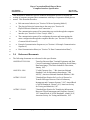
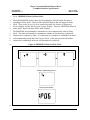
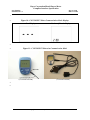
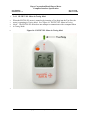
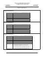
When off, the BREEZE® meter appears as shown in "Figure 1: BREEZE® Meter Off".
The BREEZE® meter may be turned on in various modes, including Test Mode, My
Setup Mode, My Results Mode, and Home Mode.
5
BREEZE® Meter Operating Modes
Figure 1: BREEZE® Meter Off
6
7
Figure 2: BREEZE® 2 Meter Off
8
© Copyright 2000-2006 Bayer HealthCare, Diabetes Care
Bayer Corporation Blood Glucose Meter
Computer Interface Specification
Part Number:
99993952, Rev. C
Page 11 of 98
Date: 11/21/06
1
2
3
4
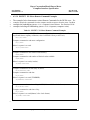
When the BREEZE® meter is turned on, the meter runs a power-on display test during
which all display elements are briefly on. The meter will then enter the operating mode
as described in the following sections.
5
The BREEZE® meter is turned off from any mode by pressing the On/Off button.
6
3.1.1
BREEZE® Meter in Test Mode
7
8
9
10
11
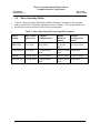
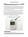
When the BREEZE® meter is turned on by pulling the Slide all the way out and pushing
the Slide all the way back, a sensor is presented for a test and the meter is operating in
Test Mode. "Figure 3: BREEZE® Meter in Test Mode" depicts the initial Test Mode
display. The BREEZE® meter does not attempt to communicate with a computer when
in Test Mode.
12
Figure 3: BREEZE® Meter in Test Mode
13
14
15
16
3.1.2
BREEZE® Meter in My Setup Mode
17
18
19
20
21
22
When the BREEZE® meter is turned on by pushing the Setup Button inside the advanced
features door, the meter is operating in My Setup Mode. My Setup Mode is used to view
and set various meter configuration settings. My Setup Mode may be useful in
developing software to communicate with the meter. Refer to the User's Guide packaged
with the meter for more information on the operation of My Setup Mode. The BREEZE®
meter does not attempt to communicate with a computer when in My Setup Mode.
23
3.1.3
24
25
26
27
28
29
30
When the BREEZE® meter is turned on by pushing the Memory Button inside the
advanced features door, the meter is operating in My Results Mode. My Results Mode is
used to view and clear blood glucose results stored in the meter. My Results Mode may
be useful in developing software to communicate with the meter. Refer to the User's
Guide packaged with the meter for more information on the operation of My Results
Mode. The BREEZE® meter does not attempt to communicate with a computer when in
My Results Mode.
BREEZE® Meter in My Results Mode
© Copyright 2000-2006 Bayer HealthCare, Diabetes Care
Bayer Corporation Blood Glucose Meter
Computer Interface Specification
Part Number:
99993952, Rev. C
Page 12 of 98
Date: 11/21/06
1
3.1.4
BREEZE® Meter in Home Mode
2
3
4
5
6
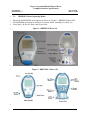
When the BREEZE® meter is turned on by pushing the On/Off button, the meter is
operating in Home Mode. There are three possible displays that will appear in Home
Mode. They are the Insert New Disk Animation display, the Number of Remaining
Sensors display, and the Edit Program Number display. "Figure 4: BREEZE® Meter in
Home Mode" depicts the three Home Mode displays.
7
8
9
10
11
The BREEZE® meter attempts to communicate with a computer only when in Home
Mode. The meter will attempt to communicate whether or not the meter is physically
connected to a computer or cable. If a connection to a computer is established, the meter
will automatically switch into Data Transfer Mode. If the meter remains idle and no
connection is established, the meter will automatically switch off.
12
Figure 4: BREEZE® Meter in Home Mode
Insert New Disk Animation
Number of Remaining Sensors
Edit Program Number
13
© Copyright 2000-2006 Bayer HealthCare, Diabetes Care
Bayer Corporation Blood Glucose Meter
Computer Interface Specification
Part Number:
99993952, Rev. C
Page 13 of 98
Date: 11/21/06
1
3.1.5
BREEZE® Meter in Data Transfer Mode/Remote Command Mode
2
3
When the BREEZE® meter enters Data Transfer Mode, the meter will display three
dashes while the initial header information is sent (Initial Data Transfer Mode Display).
4
5
While the meter is sending test results, the meter will display animated dashes and the
number of results that remain to be sent (Data Transfer Mode Animated Display).
6
7
8
9
10
11
12
After all test results stored in the meter are sent, the meter will display three dashes while
the meter waits for Remote Command Mode to start and while the computer sends remote
commands to the meter (Remote Command Mode Display). "Figure 5: BREEZE® Meter
Data Transfer Mode/Remote Command Mode" depicts each of the possible Data
Transfer Mode/Remote Command Mode displays. "Figure 6: BREEZE® Meter in Data
Transfer Mode" depicts the BREEZE® meter with a representative Data Transfer Mode
display.
13
Figure 5: BREEZE® Meter Data Transfer Mode/Remote Command Mode Displays
Initial Data Transfer Mode Display
Data Transfer Mode Animated Display
Remote Command Mode Display
14
© Copyright 2000-2006 Bayer HealthCare, Diabetes Care
Bayer Corporation Blood Glucose Meter
Computer Interface Specification
Part Number:
99993952, Rev. C
Page 14 of 98
Date: 11/21/06
1
2
Figure 6: BREEZE® Meter in Data Transfer Mode
3
4
5
6
7
8
© Copyright 2000-2006 Bayer HealthCare, Diabetes Care
Bayer Corporation Blood Glucose Meter
Computer Interface Specification
Part Number:
99993952, Rev. C
Page 15 of 98
Date: 11/21/06
1
3.2
CONTOUR™ Meter Operating Modes
2
3
4
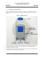
When off, the CONTOUR™ meter appears as shown in "Figure 7: CONTOUR™ Meter
Off". The CONTOUR™ meter may be turned on in various modes, including Test Mode,
Setup Mode, Memory Recall Mode, and Communication Mode.
5
Figure 7: CONTOUR™ Meter Off
(15-second version)
(5-second version)
6
7
8
9
When the CONTOUR™ meter is turned on, the meter runs a power-on display test
during which all display elements are briefly on. The meter will then enter the operating
mode as described in the following sections.
10
11
12
The CONTOUR™ meter is turned off from Communication Mode by unplugging the
interface cable. The CONTOUR™ meter is turned off from Test Mode, Setup Mode, or
Memory Recall Mode by pressing the M button.
© Copyright 2000-2006 Bayer HealthCare, Diabetes Care
Bayer Corporation Blood Glucose Meter
Computer Interface Specification
Part Number:
99993952, Rev. C
Page 16 of 98
Date: 11/21/06
1
3.2.1
CONTOUR™ Meter in Test Mode
2
3
4
5
When the CONTOUR™ meter is turned on by inserting a Test Strip into the Test Slot,
the meter is operating in Test Mode. See "Figure 8: CONTOUR™ Meter (15-second
version) in Test Mode". The CONTOUR™ meter does not attempt to communicate with
a computer when in Test Mode.
6
Figure 8: CONTOUR™ Meter (15-second version) in Test Mode
7
8
9
10
3.2.2
CONTOUR™ Meter in Setup Mode
11
12
13
14
15
16
When the CONTOUR™ meter is turned on by pushing and holding the "M" Button, the
meter is operating in Setup Mode. The CONTOUR™ meter does not attempt to
communicate with a computer when in Setup Mode. Setup Mode is used to set and view
various meter configuration settings. Refer to the User's Guide packaged with the meter
for more information on the operation of Setup Mode.
© Copyright 2000-2006 Bayer HealthCare, Diabetes Care
Bayer Corporation Blood Glucose Meter
Computer Interface Specification
Part Number:
99993952, Rev. C
1
3.2.3
Page 17 of 98
Date: 11/21/06
CONTOUR™ Meter in Memory Recall Mode
2
3
4
5
6
7
8
9
10
When the CONTOUR™ meter is turned on by briefly pressing the "M" Button, the meter
is operating in Memory Recall Mode. See "Figure 9: CONTOUR™ Meters in Memory
Recall Mode". The 5-second CONTOUR™ meter will attempt to communicate with a
computer if the cable is inserted while the meter is in Memory Recall Mode. The 15second CONTOUR™ meter will not attempt to communicate with a computer while the
meter is in Memory Recall Mode. Memory Recall Mode is used to view and clear blood
glucose results stored in the meter. Memory Recall Mode may be useful in developing
software to communicate with the meter. Refer to the User's Guide packaged with the
meter for more information on the operation of Memory Recall Mode.
11
Figure 9: CONTOUR™ Meters in Memory Recall Mode
(15-second version)
(5-second version)
12
13
14
15
© Copyright 2000-2006 Bayer HealthCare, Diabetes Care
Bayer Corporation Blood Glucose Meter
Computer Interface Specification
Part Number:
99993952, Rev. C
1
2
3
4
5
Page 18 of 98
Date: 11/21/06
3.2.4 CONTOUR™ Meter in Communication Mode
When the CONTOUR™ meter is turned on by first inserting the computer interface cable
and then briefly pressing the "M" button, the meter operates in Communication Mode1.
The CONTOUR™ meter attempts to communicate with a computer when in
Communication Mode, whether or not the meter is physically connected to a computer.
12
While the CONTOUR™ meter is in Communication Mode, the meter will display three
flashing horizontal segments (Dash Display) under the following conditions:
1) prior to connection being established
2) while the initial header information is transmitted
3) while the interface is inactive, but the meter has not timed out
4) after all test results stored in the meter are transmitted
5) while the computer sends remote commands to the meter
13
14
15
16
If communication is established, glucose results in memory will be transmitted upon
request of the host computer. While the clinical results in memory are being transmitted,
the meter will display the number of results remaining to transmit (Number of Results
Display).
17
When the interface cable plug is removed from the meter, the meter turns off.
6
7
8
9
10
11
"
18
19
20
Figure 10: CONTOUR™ Meter Communication Mode Displays" depicts each of the
possible Communication Mode displays.
21
22
"Figure 11: CONTOUR™ Meters in Communication Mode" depicts the CONTOUR™
meter with a representative Communication Mode display.
23
1
-
-
Special cases:
If the computer interface cable is inserted into the data port after the meter is already On (and the Power On Self
Test screen is no longer displayed), the 15-second CONTOUR™ meter enters Memory Recall Mode, not
Communication Mode.
If the meter is turned on by pressing and holding the "M" button for more than three seconds and a cable is
connected to the meter, the meter will enter Communication Mode, instead of Setup Mode.
If the meter is turned on by inserting a sensor into the meter, inserting the computer interface cable into the data
port at any time will have no effect. The meter will enter and stay in Test Mode.
© Copyright 2000-2006 Bayer HealthCare, Diabetes Care
Bayer Corporation Blood Glucose Meter
Computer Interface Specification
Part Number:
99993952, Rev. C
Page 19 of 98
Date: 11/21/06
1
2
Figure 10: CONTOUR™ Meter Communication Mode Displays
Dash Display
Number of Results Display
3
4
Figure 11: CONTOUR™ Meters in Communication Mode
(15-second version)
(5-second version)
5
6
© Copyright 2000-2006 Bayer HealthCare, Diabetes Care
Bayer Corporation Blood Glucose Meter
Computer Interface Specification
Part Number:
99993952, Rev. C
Page 20 of 98
Date: 11/21/06
1
2
3.3
3
4
5
When off, the DEX® meter appears as shown in "Figure 12: DEX® Meter Off". The
DEX® meter may be turned on in various modes, including Testing Mode and Features
Mode.
6
DEX® Meter Operating Modes
Figure 12: DEX® Meter Off
7
8
9
10
When the DEX® meter is turned on, the meter runs a power-on display test during which
all display elements are briefly on. The meter will then enter the operating mode as
described in the following sections.
11
12
The DEX® meter is turned OFF by moving the slide to the back position and remains off
while the Slide switch is in the backward position.
© Copyright 2000-2006 Bayer HealthCare, Diabetes Care
Bayer Corporation Blood Glucose Meter
Computer Interface Specification
Part Number:
99993952, Rev. C
Page 21 of 98
Date: 11/21/06
1
3.3.1
DEX® Meter in Testing Mode
2
3
4
5
When the DEX® meter is turned on by sliding the Slide forward with the Thumb Grip in
the left position, a sensor is presented for a test and the meter is operating in Testing
Mode. See "Figure 13: DEX® Meter in Testing Mode". The DEX® meter does not
attempt to communicate with a computer when in Testing Mode.
6
Figure 13: DEX® Meter in Testing Mode
7
© Copyright 2000-2006 Bayer HealthCare, Diabetes Care
Bayer Corporation Blood Glucose Meter
Computer Interface Specification
Part Number:
99993952, Rev. C
Page 22 of 98
Date: 11/21/06
1
3.3.2
2
3
4
5
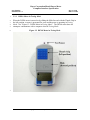
When the DEX® meter is turned on by sliding the Slide forward with the Thumb Grip in
the right position, the meter is operating in Features Mode. See "Figure 14: DEX®
Meter in Features Mode". The DEX® meter attempts to communicate with a computer
when in Features Mode, whether or not the meter is physically connected to a computer.
6
7
8
9
Features Mode is also used to set and view various meter configuration settings and to
view blood glucose test results stored in the meter. These Features Mode capabilities
may be useful in developing software to communicate with the meter. Refer to the User's
Guide packaged with the meter for more information.
10
11
12
13
14
15
16
17
When the DEX® meter is operating in Features Mode and establishes a connection with
a computer, the meter will initially display three dashes ("---") in the result area of the
display and the meter will beep. During the transfer of the stored results in memory
(Data Transfer Mode), as results are sent, the number of results remaining to be
transferred is displayed in the result area of the display. Leading zeroes are shown when
showing the number of results remaining to be transferred; the display counts down to
"000". When all results have been sent and during Remote Command Mode, three dashes
("---") are displayed in the result area of the display and the meter will beep.
18
19
On the DEX® meter, if the key labeled "A" is pushed or the meter is turned "OFF"
before Data Transfer Mode is entered, then Data Transfer Mode is not entered.
20
DEX® Meter in Features Mode
Figure 14: DEX® Meter in Features Mode
21
© Copyright 2000-2006 Bayer HealthCare, Diabetes Care
Bayer Corporation Blood Glucose Meter
Computer Interface Specification
Part Number:
99993952, Rev. C
Page 23 of 98
Date: 11/21/06
1
3.4
ELITE™ XL Meter Operating Modes
2
3
4
When off, the ELITE™ XL meter appears as shown in "Figure 15: ELITE™ XL Meter
Off". The ELITE™ XL meter may be turned on in various modes, including Test Mode,
Setup Mode, Memory Recall Mode, and Communication Mode.
5
Figure 15: ELITE™ XL Meter Off
6
7
8
When the ELITE™ XL meter is turned on, the meter runs a power-on display test during
which all display elements are briefly on. The meter will then enter the operating mode
as described in the following sections.
9
10
11
The ELITE® XL meter is turned off from Communication Mode by unplugging the
interface cable. The ELITE® XL meter is turned off from Test Mode, Setup Mode, or
Memory Recall Mode by pressing the button.
© Copyright 2000-2006 Bayer HealthCare, Diabetes Care
Bayer Corporation Blood Glucose Meter
Computer Interface Specification
Part Number:
99993952, Rev. C
Page 24 of 98
Date: 11/21/06
1
3.4.1
ELITE™ XL Meter in Testing Mode
2
3
4
5
When the ELITE® XL meter is turned on by inserting a Test Strip into the Test Slot, the
meter is operating in Testing Mode. See "Figure 16: ELITE™ XL Meter in Testing
Mode". The ELITE® XL meter does not attempt to communicate with a computer when
in Testing Mode.
6
Figure 16: ELITE™ XL Meter in Testing Mode
7
© Copyright 2000-2006 Bayer HealthCare, Diabetes Care
Bayer Corporation Blood Glucose Meter
Computer Interface Specification
Part Number:
99993952, Rev. C
Page 25 of 98
Date: 11/21/06
1
3.4.2
2
3
4
5
6
7
When the ELITE™ XL meter is turned on by pushing and holding the Button, the meter
is operating in Setup Mode. Setup Mode is used to set and view various meter
configuration settings. Setup Mode may be useful in developing software to
communicate with the meter. Refer to the User's Guide packaged with the meter for
more information on the operation of Setup Mode. The ELITE® XL meter does not
attempt to communicate with a computer when in Setup Mode.
8
3.4.3
9
10
11
12
13
14
15
16
ELITE™ XL Meter in Setup Mode
ELITE™ XL Meter in Memory Recall Mode
When the ELITE® XL meter is turned on by briefly pressing the button, the meter is
operating in Memory Recall Mode. See "Figure 17: ELITE™ XL Meter in Memory
Recall Mode". Memory Recall Mode is used to view blood glucose test results stored in
the meter. Memory Recall Mode may be useful in developing software to communicate
with the meter. Refer to the User's Guide packaged with the meter for more information
on the operation of Memory Recall Mode. The ELITE® XL meter does not attempt to
communicate with a computer when in Memory Recall Mode.
Figure 17: ELITE™ XL Meter in Memory Recall Mode
17
© Copyright 2000-2006 Bayer HealthCare, Diabetes Care
Bayer Corporation Blood Glucose Meter
Computer Interface Specification
Part Number:
99993952, Rev. C
Page 26 of 98
Date: 11/21/06
1
3.4.4
ELITE™ XL Meter in Communications Mode
2
3
4
5
6
7
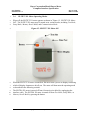
When the ELITE® XL meter is turned on by first inserting the computer interface cable
and then briefly pressing the button, the meter is operating in Communications Mode.1
See "Figure 18: ELITE™ XL Meter in Communications Mode". The ELITE® XL meter
attempts to communicate with a computer when in Communications Mode, whether or
not the meter is physically connected to a computer. When the interface cable plug is
removed from the meter, the meter turns off.
8
9
10
11
12
13
14
15
Upon entering Communication Mode, the ELITE® XL meter will initially display three
dashes ("---") in the result area of the display and the meter will beep. The 3-dash
display will continue throughout the establishment phase and while the message header is
sent. While results are sent, the number of results remaining to be transferred is
displayed in the result area of the display. Leading zeroes are shown when showing the
number of results remaining to be transferred; the display counts down to "000". When
all results have been sent and during Remote Command Mode, three dashes ("---") are
displayed in the result area of the display and the meter will beep.
16
Figure 18: ELITE™ XL Meter in Communications Mode
17
1
Note: When interfacing the Elite XL to some Windows 2000 and Windows XP computers, the port will
need to be opened on the computer prior to turning the meter on.
© Copyright 2000-2006 Bayer HealthCare, Diabetes Care
Bayer Corporation Blood Glucose Meter
Computer Interface Specification
Part Number:
99993952, Rev. C
Page 27 of 98
Date: 11/21/06
1
4.0
Physical/Electrical Interface and Connection
2
3
4
5
6
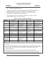
Certain Bayer Corporation blood glucose meters are equipped with a data communication
port for communication with a computer. The meter’s computer interface port connects
to the EIA-232 interface port (serial port) of a computer through a Bayer Corporation
computer interface cable. See "Section 4.2 Serial Interface Cables" for more information
about the Bayer Corporation computer interface cable.
7
4.1
EIA-232 Based Interface
8
9
10
11
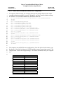
The serial interface used by all Bayer Corporation blood glucose meters is based upon the
EIA-232 standard. The electrical and physical characteristics of the serial interface for
all Bayer Corporation blood glucose meters are summarized in "Table 3: Meter Serial
Interface Physical and Electrical Characteristics".
12
Table 3: Meter Serial Interface Physical and Electrical Characteristics
Meter Family
Interface
Characteristic
Connector on
meter
EIA-232 variant
type (see note 1)
BREEZE®
CONTOUR™
DEX®
ELITE® XL
3.5 mm stereo phono
jack
3.5 mm stereo phono
jack
Custom connector jack
3.5 mm stereo phono
jack
type 2
type 2
Marking: –15 V to –3 V
Spacing: +15 V to + 3 V
Marking: –15 V to –3 V
Spacing: +15 V to + 3 V
either type 1, or type 2
(see note 3)
Marking: –15 V to –3 V
Spacing: +15 V to + 3 V
asynchronous
asynchronous
asynchronous
7-bit ASCII serial
7-bit ASCII serial
7-bit ASCII serial
7-bit ASCII serial
1 start bit
8 data bits, MSB set to 0
one stop bit
no parity
1 start bit
8 data bits, MSB set to 0
one stop bit
no parity
1 start bit
8 data bits, MSB set to 0
one stop bit
no parity
1 start bit
8 data bits, MSB set to 0
one stop bit
no parity
Baud Rate
Handshake
9600 bps
9600 bps
9600 bps
9600 bps
None
None
None
None
duplex (see note 2)
half
half
half
half
Data Signal levels
Communication
Data Code
Character Format
type 2
Marking: –15 V to –3 V
Spacing: +15 V to + 3 V
asynchronous
Notes:
1. See "Section 4.1 EIA-232 Based Interface" for an explanation of the EIA-232 variations used by the Bayer
Corporation blood glucose meters. See "Table 4: EIA-232 Variants Descriptions" for a list of Interface
connections used by each interface variant.
2. The mode of operation of all Bayer blood glucose meters’ serial interface is half-duplex. None of the meters
supports full-duplex operation; i.e., the meter and computer cannot both transmit characters at the same
time.DEX® meter will have either type 1 or type 2, never both types.
13
© Copyright 2000-2006 Bayer HealthCare, Diabetes Care
Bayer Corporation Blood Glucose Meter
Computer Interface Specification
Part Number:
99993952, Rev. C
Page 28 of 98
Date: 11/21/06
1
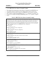
4.1.1
2
3
4
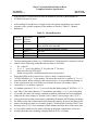
The Bayer Corporation blood glucose meters’ serial interface is not fully compliant with
the EIA-232 standard. The deviation from the EIA-232 standard is required in order to
extend meter battery life.
5
6
7
8
As indicated in "Table 3: Meter Serial Interface Physical and Electrical Characteristics",
Bayer Corporation blood glucose meters employ two distinct variants of the EIA-232
interface. An explanation of each of the EIA-232 variants is provided in
"Table 4: EIA-232 Variants Descriptions".
9
Table 4: EIA-232 Variants Descriptions
Type
EIA-232 Variants
Meters
EIA-232 Variant Description
DEX® meter
family:
1
Units with all
numeric serial
numbers
DEX® meter
family:
Units whose
serial numbers
begin with an
alpha character
2
10
All units in the
following meter
families:
BREEZE®,
CONTOUR™,
ELITE® XL
The meter uses power from the TxD signal line of the computer to
generate the negative voltage level for the marking state of the RxD
signal line. The computer must maintain the marking level (negative
voltage) on its output line (TxD) when the meter is transmitting
characters. If the meter’s receive line (TxD) is in the spacing state
(positive voltage) during meter transmission, the meter transmit line
(RxD) will not go more negative than zero volts. During spacing, the
meter transmit line (RxD) voltage level will typically be +4 volts.
The following table summarizes the computer connections required
for the type 1 EIA-232 variant:
Signal Name
GND
TxD
RxD
Cable Shield
Signal Definition
Ground
Serial data, computer to meter
Serial data, meter to computer
Shield
DB-9M
5
3
2
metal shell
DB-25F
7
2
3
metal shell
The meter uses power from the TxD signal line of the computer to
generate the negative voltage level for the marking state of the RxD
signal line and power from the DTR signal line to generate the positive
voltage level for the spacing state of the RxD signal line. The computer
must maintain the marking level (negative voltage) on its output line
(TxD) and the "ON" level (positive voltage) on its DTR line when the
meter is transmitting characters. If the meter’s receive line (TxD) is in
the spacing state (positive voltage) during meter transmission, the meter
transmit line (RxD) will not go more negative than zero volts. During
spacing, the meter transmit line (RxD) voltage level will typically operate
at a voltage slightly less than the DTR line.
The following table summarizes the computer connections required
for the type 2 EIA-232 variant:
Signal Name
GND
TxD
RxD
DTR
Cable Shield
Signal Definition
Ground
Serial data, computer to meter
Serial data, meter to computer
interface control line from
computer
Shield
DB-9
5
3
2
4
DB-25
7
2
3
20
metal shell
metal shell
© Copyright 2000-2006 Bayer HealthCare, Diabetes Care
Bayer Corporation Blood Glucose Meter
Computer Interface Specification
Part Number:
99993952, Rev. C
Page 29 of 98
Date: 11/21/06
1
4.2
Serial Interface Cables
2
3
4
5
In order to connect a Bayer blood glucose meter to a computer, Bayer Corporation
provides custom serial interface connector cable(s). The Bayer Corporation custom serial
interface connector cable(s) provide compatibility with one or more meter family by
incorporating one or more combination of the following characteristics, as appropriate:
6
-
EIA-232 variant — type 1 and/or type 2
7
-
Meter connector(s) — 3.5mm stereo phono and/or custom
8
-
Computer connector — DB-9F or DB-25F
9
-
Signal level conversion circuitry
10
11
12
"Table 5: Serial Interface Cable Characteristics and Compatibility" summarizes the
operating characteristics of the various Bayer Corporation serial interface cables and the
meter compatibility for each cable.
13
14
15
16
17
18
19
20
Each Bayer Corporation Serial Interface cable provides a computer connector and one or
two meter mating connector(s). Bayer Corporation blood glucose meters employ two
types of connector ports (custom and 3.5 mm stereo phono) as well as two different EIA232 variants (type 1 and type 2, as defined in "Section 4.1.1 EIA-232 Variants"). See
"Table 3: Meter Serial Interface Physical and Electrical Characteristics". Each custom
Bayer Corporation Serial Interface cable contains a level conversion circuit to permit
connection to the EIA-232 interface port (serial port) of a computer since the computer's
and meter's serial signals operate at different voltage levels.
21
22
23
Bayer recommends using the Ascensia® Data Cable (part number 40453276) to
communicate with all Bayer blood glucose meters because the Ascensia® Data Cable is
compatible with all Bayer Corporation blood glucose meters.
24
25
26
Caution: Use of any cable other than the compatible Bayer Corporation cable shown in
"Table 5: Serial Interface Cable Characteristics and Compatibility" may damage the
meter or cause electrical interference with other devices.
27
28
29
30
Note: When the computer is connected to any Bayer Corporation blood glucose meter
with the Ascensia® Data Cable (part number 40453276), the computer must turn on the
DTR interface line before data communication is possible (see "Section 4.1 EIA-232
Based Interface").
31
32
Note: The Glucometer® DEX® Data Cable (part number 40453244) and the
Glucometer ELITE® XL Data Cable (part number 40453249) are obsolete.
33
© Copyright 2000-2006 Bayer HealthCare, Diabetes Care
Bayer Corporation Blood Glucose Meter
Computer Interface Specification
Part Number:
99993952, Rev. C
Page 30 of 98
Date: 11/21/06
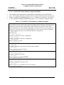
Table 5: Serial Interface Cable Characteristics and Compatibility
1
Meter Family Compatibility
5.
6.
Meter
Connector
Interface
Type
(see note 1)
CONTOUR™
Notes:
1.
2.
3.
4.
Computer
Connector
BREEZE®
Glucometer® DEX® Data Cable
(see notes 3 and 4)
Glucometer ELITE® XL Data Cable
(see note 3)
Product
Code
ELITE™ XL
Ascensia® Data Cable
(see note 2)
Part
Number
DEX®
Cable Name
1 and 2
all
all
all
all
40453276
3479
DB-9F
Custom plug
and
3.5 mm stereo
phono plug
40453244
3427
DB-9F
(see note 5)
Custom plug
1
partial
(see note 4)
n/a
n/a
n/a
40453249
3437
DB-25F
(see note 6)
3.5 mm stereo
phono plug
2
n/a
all
all
all
See "Section 4.1 EIA-232 Based Interface" for details.
Cable 40453276 is compatible with all Bayer Corporation blood glucose meters. Bayer recommends using cable 40453276 exclusively.
Cables 40453244 and 40453249 are obsolete; compatibility is listed for reference purposes. Bayer recommends use of cable 40453276.
Cable 40453244 is compatible only with DEX® family meters having all numeric serial numbers. DEX® family meters with serial numbers beginning
with an ‘A’ character are compatible only with cable 40453276.
The Glucometer® DEX® Data Cable package (Bayer Part Number 40453244) includes a DB-9F to DB-25F adapter. The cable and adapter are both
marked with part number 40453244. The adapter marked with part number 40453244 should NOT be used with the Ascensia® Data Cable, regardless
of which type of meter is connected.
The Glucometer ELITE® XL Data Cable package (Bayer Part Number 40453249) includes a DB-25F to DB-9F adapter (Bayer Part Number
4000006).
© Copyright 2000-2006 Bayer HealthCare, Diabetes Care
Bayer Corporation Blood Glucose Meter
Computer Interface Specification
Part Number:
99993952, Rev. C
Page 31 of 98
Date: 11/21/06
1
4.2.1
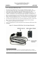
Ascensia® Data Cable
2
3
4
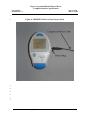
The Ascensia® Data Cable (part number 40453276) is compatible with all Bayer
Corporation blood glucose meters. Bayer recommends using the Ascensia® Data Cable
exclusively to communicate with all Bayer Corporation blood glucose meters.
5
6
7
8
The Ascensia® Data Cable is available as Bayer Corporation Product Code 3479. The
Ascensia® Data Cable is also bundled with the latest versions of the Bayer Corporation
Diabetes Information Management System software package (Ascensia™ WINGlucofacts®
and Ascensia™ WINGlucofacts® Professional).
9
10
11
If necessary, a standard DB-9M to DB-25F adapter may be used with the Ascensia®
Data Cable. Bayer does not provide an adapter with the Ascensia® Data Cable since
most computers utilize a DB-9M connector.
12
13
Figure 19 through Figure 22 provide descriptions of the Ascensia® Data Cable and
standard DB-9F to DB-25F adapter (optional, user supplied).
14
Figure 19: Ascensia® Data Cable Illustration
15
© Copyright 2000-2006 Bayer HealthCare, Diabetes Care
Bayer Corporation Blood Glucose Meter
Computer Interface Specification
Part Number:
99993952, Rev. C
Page 32 of 98
Date: 11/21/06
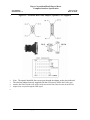
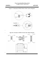
Figure 20: Ascensia® Data Cable Connector Diagrams
1
2
Figure 21: Ascensia® Data Cable Connector Pinout
3
COMPUTER SIGNAL
P1 PIN #
P2 PIN #
P3 PIN #
GND
TxD
RxD
DTR3
CABLE SHIELD
5
3
2
4
METAL SHELL
SLEEVE
TIP
RING
n/a
SLEEVE
2
3
1
n/a
n/a
3
The DTR signal is used by the signal level conversion circuitry within the cable. No connection to the
meter is required.
© Copyright 2000-2006 Bayer HealthCare, Diabetes Care
Bayer Corporation Blood Glucose Meter
Computer Interface Specification
Part Number:
99993952, Rev. C
1
2
3
4
5
Page 33 of 98
Date: 11/21/06
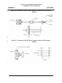
Figure 22: Ascensia® Data Cable Adapter (Optional, User-Supplied)
Note: The signals identified above must pass through the adapter on the pins indicated.
The obsolete adapter formerly supplied with the Glucometer® DEX® Data Cable (part
number 40453244) should not be used with the Ascensia® Data Cable because the 40453244
adapter does not pass through the DTR signal.
6
© Copyright 2000-2006 Bayer HealthCare, Diabetes Care
Bayer Corporation Blood Glucose Meter
Computer Interface Specification
Part Number:
99993952, Rev. C
Page 34 of 98
Date: 11/21/06
1
4.2.2
Glucometer® DEX® Data Cable
2
3
4
5
6
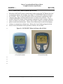
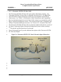
The Glucometer® DEX® Data Cable (part number 40453244) is obsolete. The
Glucometer® DEX® Data Cable is only compatible with "older" DEX® family blood
glucose meters and is incompatible with "newer" DEX®4 family meters and is
incompatible with all ELITE™ XL, BREEZE®, and CONTOUR™ family meters. See
"Table 5: Serial Interface Cable Characteristics and Compatibility, especially Note 4".
7
8
9
Bayer recommends using the Ascensia® Data Cable exclusively to communicate with all
Bayer Corporation blood glucose meters. The Ascensia® Data Cable is compatible with
all Bayer Corporation blood glucose meters. See "Section 4.2.1 Ascensia® Data Cable".
10
11
12
The Glucometer® DEX® Data Cable was formerly bundled with obsolete versions of the
Bayer Corporation Diabetes Information Management System software packages,
WIN
Glucofacts® and WinGlucofacts® Professional.
13
14
Figure 23 through Figure 25 provide descriptions of the Glucometer® DEX® Data Cable
and adapter.
Figure 23: Glucometer® DEX® Data Cable and Adapter Illustration
4
"Newer" DEX® family blood glucose meters have serial numbers beginning with an "A" character.
"Older" DEX® family blood glucose meters have serial numbers beginning with a numeric character ("0"
to "9").
© Copyright 2000-2006 Bayer HealthCare, Diabetes Care
Bayer Corporation Blood Glucose Meter
Computer Interface Specification
Part Number:
99993952, Rev. C
1
2
Page 35 of 98
Date: 11/21/06
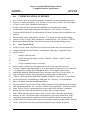
Figure 24: Glucometer® DEX® Meter Computer Interface Cable Connector
Diagram
3
4
5
6
Figure 25: Glucometer® DEX® Meter Computer Interface Cable Adapter
Diagram
7
© Copyright 2000-2006 Bayer HealthCare, Diabetes Care
Bayer Corporation Blood Glucose Meter
Computer Interface Specification
Part Number:
99993952, Rev. C
Page 36 of 98
Date: 11/21/06
1
4.2.3
2
3
4
5
The Glucometer ELITE® XL Data Cable (part number 40453249) is obsolete. The
Glucometer ELITE® XL Data Cable is compatible with all ELITE™ XL, BREEZE®,
and CONTOUR™ family blood glucose meters but is incompatible with all DEX®
family meters. See "Table 5: Serial Interface Cable Characteristics and Compatibility".
6
7
8
Bayer recommends using the Ascensia® Data Cable exclusively to communicate with all
Bayer Corporation blood glucose meters. The Ascensia® Data Cable is compatible with
all Bayer Corporation blood glucose meters. See "Section 4.2.1 Ascensia® Data Cable".
9
10
11
The Glucometer ELITE® XL Data Cable was formerly bundled with obsolete versions of
the Bayer Corporation Diabetes Information Management System software packages,
WIN
Glucofacts® and WinGlucofacts® Professional.
12
13
Figure 26 through Figure 28 provide additional descriptions of the Glucometer ELITE®
XL Cable and Adapter.
14
Glucometer ELITE® XL Data Cable
Figure 26: Glucometer ELITE® XL Data Cable and Adapter Illustration
15
16
17
18
© Copyright 2000-2006 Bayer HealthCare, Diabetes Care
Bayer Corporation Blood Glucose Meter
Computer Interface Specification
Part Number:
99993952, Rev. C
1
Page 37 of 98
Date: 11/21/06
Figure 27: Glucometer ELITE® XL Data Cable Connector Diagrams
2
3
Figure 28: Glucometer ELITE® XL Data Cable Adapter Diagram
4
© Copyright 2000-2006 Bayer HealthCare, Diabetes Care
Bayer Corporation Blood Glucose Meter
Computer Interface Specification
Part Number:
99993952, Rev. C
Page 38 of 98
Date: 11/21/06
1
5.0
ASCII Control Character Notation
2
3
4
5
The communication protocol utilizes the ASCII (American Standard Code for
Information Interchange) character set, as defined in the ANSI (American National
Standards Institute) standard ANSI X3.4-1986, "Coded Character Sets – 7-Bit American
Standard Code for Information Interchange (7-Bit ASCII)".
6
7
8
9
10
The ASCII character set includes non-printable control characters. In this document, the
convention for displaying control characters uses the notation <XYZ>. This indicates the
single control character whose mnemonic is XYZ not the sequence of characters "<",
"X", "Y", "Z", ">". For example, <CR> stands for the Carriage Return control character
that is represented by decimal value 13 or hexadecimal value 0x0D.
11
12
The ASCII control characters referenced in this document are listed in "Table 6: ASCII
Control Characters".
Table 6: ASCII Control Characters
13
ASCII
Character
Abbreviation
<ACK>
<CR>
<ENQ>
<EOT>
<ETB>
<ETX>
<LF>
<NAK>
<STX>
Meaning
Acknowledge
Carriage Return
Enquiry
End of Transmission
End of Transmission Block
End of Text
Line Feed
Negative Acknowledge
Start of Text
Hexadecimal
Character
Code
0x06
0x0D
0x05
0x04
0x17
0x03
0x0A
0x15
0x02
14
© Copyright 2000-2006 Bayer HealthCare, Diabetes Care
Decimal
Character
Code
6
13
5
4
23
3
10
21
2
Bayer Corporation Blood Glucose Meter
Computer Interface Specification
Part Number:
99993952, Rev. C
Page 39 of 98
Date: 11/21/06
1
6.0
COMMUNICATION OVERVIEW
2
3
4
Data Transfer Mode provides the capability to transfer test result information from the
meter to a connected computer. See "Section 6.1 Data Transfer Mode" for a description
of Data Transfer Mode capabilities and protocol.
5
6
7
8
Remote Command Mode provides the capability to interrogate and set meter
configurations via the meter/computer serial interface. See "Section 6.2 Remote
Command Mode Protocol" for a description of Remote Command Mode capabilities and
protocol.
9
10
11
DEX® family meters with software version 1.27 or newer provide a modem-dialing
feature for Data Transfer Mode and Remote Command Mode. See "Section 6.3 DEX®
Meter Smart Modem Dialing" for a full description of the modem-dialing feature.
12
6.1
13
14
15
In Data Transfer Mode, all clinical test results stored in the meter are transferred to a
computer through the serial interface, including the following, as applicable to the
specific meter:
Data Transfer Mode
16
-
patient’s clinical results
17
18
-
results with special markers (such as "deleted", "edited", "control", and/or
"temperature")
19
-
14-day computed average or averages
20
21
22
23
24
25
26
27
When a meter is turned on in the appropriate mode for the particular meter (see
"Section 3.0 Meter Operating Modes"), the meter attempts to determine if it is connected
to a computer by entering the Establishment Phase. If a computer connection is
established during the Establishment Phase, the meter enters Data Transfer Mode. As
long as the meter remains in the appropriate operating mode (as indicated in
"Table 2: Meter Operating Mode and Capability Summary"), then Data Transfer Mode
can be reentered by re-establishing a connection. See "Section 6.1.2 Establishment
Phase" for details about the Establishment Phase.
28
29
30
31
The data transfer (Data Transfer Mode) will be terminated if the operator turns the meter
OFF during data transfer. See "Section 3.0 Meter Operating Modes". If the data transfer
(Data Transfer Mode) is terminated prior to the receipt of the Message Terminator
Record, the test results data should not be used by the receiving computer.
32
33
34
35
36
Note: When clinical results are sent in Data Transfer Mode, all results in the meter’s
memory are sent. This might include results that were previously transmitted. If the
computer system maintains a database of clinical results by patient, it must properly
account for the fact that the meter may have previously sent some of the patient’s clinical
results. It should not treat this repeated information as new data for the patient.
37
© Copyright 2000-2006 Bayer HealthCare, Diabetes Care
Bayer Corporation Blood Glucose Meter
Computer Interface Specification
Part Number:
99993952, Rev. C
Page 40 of 98
Date: 11/21/06
1
2
3
4
5
6
During Data Transfer Mode, test results are sent in the order they were run on the meter,
regardless of the "time stamp" of the result. The most recently produced result is sent last
(first-in, first-out). Clinical results (including results marked as deleted and/or edited)
may be mixed with control solution results; the preceding Test Order Record indicates
the specimen type. The glucose average reading, or readings and average preset times,
are sent preceding the test results, as appropriate based upon meter type.
7
8
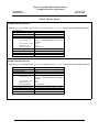
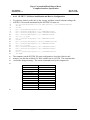
A summary of the information transmitted during Data Transfer Mode is provided in
"Table 7: Data Transfer Mode Summary ".
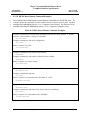
Table 7: Data Transfer Mode Summary
9
Data
Version
Meter
Identification
Description
Meter software version
Meter product code and meter serial number.
The "meter product code", which is transmitted in the Header
Record as a component of the Sender ID field, defines the meter
family to which the individual meter belongs.
Valid meter product codes are:
Meter Family Product Code(s)
BREEZE®
CONTOUR™
DEX®
ELITE® XL
Clinical Results
for Blood
Samples
Control Solution
Results for
Control Samples
Calculated
Results
Bayer6115 or Bayer6116
Bayer7150
Bayer3950
Bayer3883
The "meter serial number", which is transmitted in the Header
Record as a component of the Sender ID field, is unique for each
Bayer blood glucose meter and may be used to associate a particular
meter to a specific patient’s blood glucose test results.
Glucose value, glucose units of measure, date, time, result markers
and flags, reference method, clinical result designation
Glucose value, glucose units of measure, date, time, result markers
and flags, reference method, control solution designation
Computed average or averages of clinical results (14 day averages)
10
© Copyright 2000-2006 Bayer HealthCare, Diabetes Care
Bayer Corporation Blood Glucose Meter
Computer Interface Specification
Part Number:
99993952, Rev. C
Page 41 of 98
Date: 11/21/06
1
6.1.1
ASTM Standards
2
3
4
5
6
7
For Data Transfer Mode, ASTM Standard E 1381-95, "Specification for Low-Level
Protocol to Transfer Messages Between Clinical Laboratory Meters and Computer
Systems", defines the low-level data transfer protocol. ASTM Standard E 1394-91,
"Standard Specification for Transferring Information Between Clinical Meters and
Computer Systems", defines the data format. The serial data characteristics of the meter
are defined in "Section 4.0 Physical/Electrical Interface and Connection".
8
6.1.2
Establishment Phase
9
10
When the meter initiates the Establishment Phase, the meter determines if the computer is
connected by initially sending an <ENQ> character.
11
12
If the computer responds within 15 seconds by sending an <ACK> character, the meter
proceeds with Data Transfer Mode.
13
14
15
If the computer responds within 15 seconds with a <NAK> character, the meter sends an
<EOT> then attempts to enter Remote Command Mode, by looking for an <ENQ>
character from the computer. Also see "Section 6.2 Remote Command Mode Protocol".
16
17
18
Any response within 15 seconds to the meter’s <ENQ> other than an <ACK> or <NAK>
character causes the meter to send an <EOT>, delay one second, then send another
<ENQ>.
19
20
21
If the computer does not respond within 15 seconds, then the meter sends an <EOT>,
delays one second, then sends another <ENQ> and waits again for a response from the
computer.
22
23
24
25
Note: One second after sending an <ENQ>, the meter may enter a low power mode.
Thus, there is a possibility that the first <ACK> sent by the computer is not read correctly.
In this case, the meter responds with an <EOT>, delays one second, then sends another
<ENQ>.
26
27
28
If a modem is detected by the DEX® meter during the Establishment Phase, it commands
the modem to call the computer of the healthcare provider. See "Section 6.3 DEX®
Meter Smart Modem Dialing".
29
© Copyright 2000-2006 Bayer HealthCare, Diabetes Care
Bayer Corporation Blood Glucose Meter
Computer Interface Specification
Part Number:
99993952, Rev. C
Page 42 of 98
Date: 11/21/06
1
6.1.3
ASTM E-1381 Frames
2
Frames are formatted per ASTM Standard E-1381.
3
6.1.3.1 Frame Structure
4
5
A frame is either an intermediate frame or an end frame. The ASTM Standard E-1381
frame structures are shown in "Table 8: ASTM E-1381 Frame Structures".
Table 8: ASTM E-1381 Frame Structures
6
Frame Type
Frame Fields
Intermediate Frame
<STX> FN text <CR> <ETB> C1 C2 <CR> <LF>
End Frame
<STX> FN text <CR> <ETX> C1 C2 <CR> <LF>
where fields are defined as follows:
Field
<STX>
FN
text
<ETB>
<ETX>
C1
C2
<CR>
<LF>
7
Description
Start of Text transmission control character
single digit Frame Number ("0" to "7")
data content of the frame
End of Transmission Block transmission control character
End of Text transmission control character
most significant character of encoded checksum ("0" to "9" and "A" to "F")
least significant character of encoded checksum ("0" to "9" and "A" to "F")
Carriage Return ASCII control character
Line Feed ASCII control character
Each frame begins with an <STX> character.
8
9
10
11
12
13
The FN, Frame Number, is a single ASCII character in the range from "0" to "7". The
Frame Number permits the receiver to distinguish between new and retransmitted frames.
The Frame Number is sent immediately following the <STX> character. The Frame
Number begins with "1" with the first frame of the transfer phase and is incremented by
one for every frame transmitted. After "7" the Frame Number rolls over to "0", and
continues in this fashion.
14
The text is the data content of the frame.
15
16
17
18
19
In intermediate frames an <ETB> character follows the message text. In end frames an
<ETX> character follows message text. The <ETB> or <ETX> is followed by a twocharacter checksum (C1 and C2), carriage return <CR>, and a line feed <LF>. During
Data Transfer Mode, the <ETX> character will accompany the Message Terminator
Record. All other records will include an <ETB> character.
© Copyright 2000-2006 Bayer HealthCare, Diabetes Care
Bayer Corporation Blood Glucose Meter
Computer Interface Specification
Part Number:
99993952, Rev. C
Page 43 of 98
Date: 11/21/06
1
2
3
C1 and C2 represent the encoded checksum of the frame. The checksum permits the
computer to detect defective frames. The checksum is encoded as two ASCII characters
transmitted after the <ETB> or <ETX> character.
4
5
Any characters that appear before the <STX> or after the <ETB> or <ETX> are to be
ignored by the computer during frame validation.
6
6.1.3.2 Frame Checksum
7
8
9
10
11
12
13
The checksum is computed by adding the binary values of the ASCII characters, but
keeping only the least significant eight bits of the result. The checksum is initialized to 0
by the <STX> character. The first character included in the checksum computation is the
Frame Number. Each character in the text is added to the checksum (modulo 256). The
last character included in the checksum computation is the frame type character (<ETB>
or <ETX>). The checksum computation does not include the <STX>, the checksum
characters, or the trailing <CR> and <LF>.
14
15
16
17
The checksum is an 8-bit integer that can be considered as two groups of 4 bits. The
checksum is encoded by converting the groups of 4 bits into the ASCII characters of
hexadecimal representation ("0" to "9" or "A" to "F"). The two ASCII characters are
transmitted as the encoded checksum with the most significant character first (C1).
18
19
20
21
Example: Suppose the value of the checksum is computed to be decimal 122. The
decimal number 122 can be represented as 01111010 in binary or as 0x7A in
hexadecimal. The encoded checksum is transmitted as the ASCII character "7" followed
by the ASCII character "A".
22
6.1.3.3 Defective Frames
23
24
A Frame Number is valid if it is equal to the last accepted Frame Number (indicating a
retransmit) or is one number higher than the last accepted Frame Number.
25
26
31
The computer indicates it has received a defective frame by transmitting a <NAK> to the
meter. A frame is to be rejected for any of the following reasons:
- a character parity error is detected by the computer
- a character framing error is detected by the computer
- the checksum computed on the received frame does not match the encoded checksum
value received in the frame
- the Frame Number is not valid
32
33
34
35
36
37
Upon receiving a <NAK> or any character except an <ACK> or <EOT> in response to a
transmitted frame, the meter increments a retransmit counter and retransmits the frame
with the same Frame Number. If the retransmit counter indicates that a particular frame
was sent, but not acknowledged, six times, then the meter aborts Data Transfer Mode by
going to the termination phase (sending an <EOT>). An abort provides an escape from a
condition where the transfer phase cannot continue.
27
28
29
30
© Copyright 2000-2006 Bayer HealthCare, Diabetes Care
Bayer Corporation Blood Glucose Meter
Computer Interface Specification
Part Number:
99993952, Rev. C
Page 44 of 98
Date: 11/21/06
1
6.1.4
2
3
4
Each E-1394 record is sent as a separate E-1381 frame. This structure is a design
decision, not a requirement of the ASTM standards (record boundaries do not have to be
tied to frame boundaries).
5
6
7
8
A message is transmitted as a number of variable length records. Each record contains
multiple variable length fields. A message always starts with a Header Record. A
Patient Record follows the Header Record. One or more Test Order Records and Result
Records follow. The message always ends with a Message Terminator Record.
9
10
11
ASTM E-1394 Records
The following sections provide detail about the record types listed above. Example
records/frames are shown complete with the E-1381 framing characters (i.e. <STX>,
Frame Number, <ETB>, <ETX>, checksum characters, and trailing <CR><LF>).
12
© Copyright 2000-2006 Bayer HealthCare, Diabetes Care
Bayer Corporation Blood Glucose Meter
Computer Interface Specification
Part Number:
99993952, Rev. C
Page 45 of 98
Date: 11/21/06
1
6.1.4.1 Header Record
2
The format of the Header Record is shown in "Table 9: Header Record".
Table 9: Header Record
Field Field Name
#
1
2
Record type
Delimiter
Definition
3
4
Not used
Access
Password
5
Sender ID
Contents
Field Type
Field Length
H
|\^&
| = field delimiter
\ = repeat delimiter
^ = component delimiter
& = escape delimiter
Not used
Used as authorization to communicate with Bayer
Corporation Diabetes Information Management
System software
p^v^s
p = meter product code
v = meter software version\EEPROM version
s = meter serial number
Char
Char
1
4
N/A
Int
N/A
1 to 6
p – Char
v – Char\Char
s – Char
p–9
v – 0 to 7\0 to 7
s – 0 to 15
N/A
N/A
N/A
N/A
N/A
N/A
Char
Char
N/A
N/A
N/A
N/A
N/A
N/A
1
1
The "meter product code" defines the meter family
to which the individual meter belongs.
Valid meter product codes are:
BREEZE®:
Bayer6115 or Bayer6116
CONTOUR™: Bayer7150
DEX®:
Bayer3950
ELITE® XL: Bayer3883
The "meter serial number" is unique for each Bayer
blood glucose meter and may be used to associate a
particular meter to a specific patient’s blood glucose test
results.
6
7
8
9
10
11
12
13
Not used
Not used
Not used
Not used
Not used
Not used
Processing ID
Version
Number of
Specification
Not used
Not used
Not used
Not used
Not used
Not used
P (indicates production meter)
1 (indicates meter follows E1394-91 standard)
© Copyright 2000-2006 Bayer HealthCare, Diabetes Care
Bayer Corporation Blood Glucose Meter
Computer Interface Specification
Part Number:
99993952, Rev. C
Page 46 of 98
Date: 11/21/06
Table 9: Header Record
Field Field Name
#
14
Date & Time
of Message
Contents
Field Type
Field Length
YYYYMMDDhhmm format
YYYY – year
MM – month
DD – day
hh – hour
mm – minute
Valid YYYYMMDD ranges are:
BREEZE®:
20010101 to 20321231
CONTOUR™: 20010101 to 20211231
DEX®:
19800101 to 20791231
ELITE® XL:
19970101 to 20161231
Valid hhmm range is
0000 to 2359 (24-hour clock format)
Char
12
Note:
Unused fields are not transmitted, but the delimiters are transmitted since the unused fields are in the
middle of the record.
Example Header Record 1:
<STX>1H|\^&||-15013|Bayer6116^1.08\0.01^6116-0000096|||||||P|1|200302031432<CR><ETB>7E<CR><LF>
Record Number
Record type
Delimiter Definition
Access Password
Sender ID
meter product code
meter software version
EEPROM version
meter serial number
Processing ID
Version Number of Specification
Date & Time of Message
Checksum
1
H
|\^&
-15013
Bayer6116 (BREEZE® meter family)
1.08
0.01
6116-0000096
P (indicates production meter)
1 (indicates meter follows E1394-91 standard)
200302031432
7E
© Copyright 2000-2006 Bayer HealthCare, Diabetes Care
Bayer Corporation Blood Glucose Meter
Computer Interface Specification
Part Number:
99993952, Rev. C
Page 47 of 98
Date: 11/21/06
Table 9: Header Record
Example Header Record 2:
<STX>1H|\^&||27719|Bayer7150^1.05\0.00^7150-0002193|||||||P|1|200302031412<CR><ETB>59<CR><LF>
Record Number
Record type
Delimiter Definition
Access Password
Sender ID
meter product code
1
H
|\^&
27719
meter software version
EEPROM version
meter serial number
Processing ID
Version Number of Specification
Date & Time of Message
Checksum
Bayer7150 (CONTOUR™ meter, 15-second
version)
1.05
0.00
7150-0002193
P (indicates production meter)
1 (indicates meter follows E1394-91 standard)
200302031412
59
Example Header Record 3:
<STX>1H|\^&||-16638|Bayer7150^2.04\0.02^7150A0001001|||||||P|1|200302031412<CR><ETB>2D<CR><LF>
Record Number
Record type
Delimiter Definition
Access Password
Sender ID
meter product code
1
H
|\^&
-16638
meter software version
EEPROM version
meter serial number
Processing ID
Version Number of Specification
Date & Time of Message
Checksum
Bayer7150 (CONTOUR™ meter , 5-second
version)
2.04
0.02
7150A0001001
P (indicates production meter)
1 (indicates meter follows E1394-91 standard)
200606211756
2D
© Copyright 2000-2006 Bayer HealthCare, Diabetes Care
Bayer Corporation Blood Glucose Meter
Computer Interface Specification
Part Number:
99993952, Rev. C
Page 48 of 98
Date: 11/21/06
Table 9: Header Record
Example Header Record 4:
<STX>1H|\^&||10876|Bayer3950^3.08\2.03^3952MA000461|||||||P|1|200302031501<CR><ETB>9A<CR><LF>
Record Number
Record type
Delimiter Definition
Access Password
Sender ID
meter product code
meter software version
EEPROM version
meter serial number
Processing ID
Version Number of Specification
Date & Time of Message
Checksum
1
H
|\^&
10876
Bayer3950 (DEX® meter family)
3.08
2.03
3952MA000461
P (indicates production meter)
1 (indicates meter follows E1394-91 standard)
200302031501
9A
Example Header Record 5:
<STX>1H|\^&||7580|Bayer3883^1.06\1.01^3899-3344530|||||||P|1|200302031353<CR><ETB>4A<CR><LF>
Record Number
Record type
Delimiter Definition
Access Password
Sender ID
meter product code
meter software version
EEPROM version
meter serial number
Processing ID
Version Number of Specification
Date & Time of Message
Checksum
1
H
|\^&
7580
Bayer3883 (ELITE™ XL meter family)
1.06
1.01
3899-3344530
P (indicates production meter)
1 (indicates meter follows E1394-91 standard)
200302031353
4A
© Copyright 2000-2006 Bayer HealthCare, Diabetes Care
Bayer Corporation Blood Glucose Meter
Computer Interface Specification
Part Number:
99993952, Rev. C
Page 49 of 98
Date: 11/21/06
1
6.1.4.2 Patient Information Record
2
3
The format of the Patient Information Record is shown in "Table 10: Patient Information
Record".
4
Table 10: Patient Information Record
Field #
1
2
3-35
Field Name
Contents
Record type
Sequence number
Not used
P
1
Not used
Field
Type
Char
Integer
N/A
Field
Length
1
1
N/A
Note:
Unused fields are not transmitted, nor are the delimiters transmitted since the
unused fields are at the end of the record.
Example Patient Information Record (all meter families):
<STX>2P|1<CR><ETB>53<CR><LF>
5
© Copyright 2000-2006 Bayer HealthCare, Diabetes Care
Bayer Corporation Blood Glucose Meter
Computer Interface Specification
Part Number:
99993952, Rev. C
Page 50 of 98
Date: 11/21/06
1
6.1.4.3 Test Order Record
2
The format of the Test Order Record is shown in "Table 11: Test Order Record".
Table 11: Test Order Record
3
Field #
1
2
3
4
5
6
7
8
9
10
11
12
13-31
Field Name
Contents
Record type
Sequence number
Specimen ID
Meter specimen ID
Universal ID
Not used
Not used
Not used
Not used
Not used
Not used
Action code
O
1, 2, etc.
Not used
Not used
Not used
Not used
Not used
Not used
Not used
Not used
Not used
Q for control specimens,
otherwise Not used
Not Used
Not Used
Field
Type
Char
Int
N/A
N/A
N/A
N/A
N/A
N/A
N/A
N/A
N/A
Char
N/A
N/A
Field
Length
1
1 to 3
N/A
N/A
N/A
N/A
N/A
N/A
N/A
N/A
N/A
1
N/A
N/A
Example Test Order Record (all meter families):
<STX>3O|1<CR><ETB>53<CR><LF>
blood results
<STX>5O|2||||||||||Q<CR><ETB>7F<CR><LF> control solution results
Notes:
1. Unused fields are not transmitted. No delimiters are transmitted for unused fields at the
end of the record. For unused fields in the middle of the record, delimiters are transmitted.
2. Caution: For DEX® meter software version 1.23, the formatting of clinical data ASTM
records varies from the standard. If the oldest glucose readings in the meter memory are
marked as glucose control specimens, they are sent in the same ASTM Test Order Record
as the glucose average readings, not in a separate Test Order Record. The Result Status
field of the Result Record must be used to determine that these results are for control
specimens (the result status is "E" for edited).
3. For all meter families, an Order Record as follows precedes control solution results:
<STX>5O|2||||||||||Q<CR><ETB>7F<CR><LF>
For CONTOUR™ meters, the Result Record will also contain an 'E' marker for control
solution results that are detected automatically by the meter. If the user marks a test result
on the CONTOUR™ meter, then the Result Record will contain 'E' and 'D' markers and the
result record will NOT be preceded by an Order Record with a 'Q'.
© Copyright 2000-2006 Bayer HealthCare, Diabetes Care
Bayer Corporation Blood Glucose Meter
Computer Interface Specification
Part Number:
99993952, Rev. C
Page 51 of 98
Date: 11/21/06
1
6.1.4.4 Result Record
2
The format of the Result Record is shown in "Table 12: Result Record".
Table 12: Result Record
Field #
Field Name
Contents
Field
Type
Field
Length
1
2
Record Type
Sequence Number
R
1, 2, etc.
Char
Int
3
Universal Test ID
^^^Glucose (for blood, deleted blood, or control solutions), or
^^^GlucoseA (for glucose grand 14 day average), or
^^^GlucoseA1 (for glucose average 1, DEX® only), or
^^^GlucoseA2 (for glucose average 2, DEX® only), or
^^^GlucoseA3 (for glucose average 3, DEX® only), or
^^^GlucoseA4 (for glucose average 4, DEX® only)
Note: ^^^ indicates that only part 4 of field 3 is used.
Char
Char
Char
Char
Char
Char
1
1 or
more
10
11
12
12
12
12
4
Data or
Measurement
Value
Clinical result, depending on the meter setup the valid range is:
BREEZE®
0, 9–601 mg/dL or 0.00, 0.50–33.39 mmol/L
CONTOUR™
0, 9–601 mg/dL or 0.00, 0.50–33.39 mmol/L
DEX®
0, 9–601 mg/dL or 0.00, 0.50–33.39 mmol/L
ELITE® XL
0, 19–601 mg/dL or 0.00, 1.06–33.39 mmol/L
Notes:
• 0 mg/dL or 0.00 mmol/L is applicable only for glucose
averages, and indicates that the average is not available.
• LO results are transmitted as 9 mg/dL or 0.50 mmol/L for
BREEZE®, CONTOUR™, and DEX®
• LO results are transmitted as 19 mg/dL or 1.06 mmol/L for
ELITE® XL
• HI results are transmitted as 601 mg/dL or 33.39 mmol/L
for BREEZE®, CONTOUR™, DEX® and ELITE® XL
mg/dL or mmol/L (depends on meter setup)
^
reference method (depends on meter setup):
Int
Int
Int
Float
Float
1
1 to 3
1 to 3
4 to 5
4 to 5
Char
^
Char
5
^
1
Int
1 to 4
5
Units^Reference
Method
B
P
C
6
Reference Ranges
whole blood
plasma
capillary
BREEZE®, CONTOUR™, or DEX®
BREEZE®, CONTOUR™, or DEX®
ELITE™ XL
Used for DEX® only.
If the Universal Test ID field is ^^^GlucoseA1, ^^^GlucoseA2,
^^^GlucoseA3, or ^^^GlucoseA4, used to report glucose average
preset time for glucose average number indicated by the Universal
Test ID field.
Format is MMMM (minutes since midnight, 0 to 1439)
© Copyright 2000-2006 Bayer HealthCare, Diabetes Care
Bayer Corporation Blood Glucose Meter
Computer Interface Specification
Part Number:
99993952, Rev. C
Page 52 of 98
Date: 11/21/06
Table 12: Result Record
Field #
Field Name
Contents
Field
Type
Field
Length
7
Result Abnormal
Flags
N/A,
Char,
or
Char\Char
N/A,
1,
or
1\1
8
User Marks
N/A
N/A
9
Result Status
Markers
None, <, >, T, <\T, or >\T (note use of repeat delimiter)
Where:
< result is
10 mg/dL
BREEZE®,
below
or
CONTOUR™,
absolute low 0.56 mmol/L
or DEX®
meter scale
20 mg/dL or 1.11 mmol/L ELITE® XL
> result is
600 mg/dL or 33.33
all meter
above
mmol/L
families
absolute high
meter scale
T marginal
This marker will be
BREEZE®
temperature
placed on results
meter only
generated with meter
temperature between 0
and 10 degrees Celsius or
between 40 and 50
degrees Celsius
Note: For CONTOUR™ and ELITE® XL, this field is unused
when reporting the GlucoseA Result Record. For BREEZE® and
DEX®, the < and > markers are used when reporting the GlucoseA
and GlucoseA1 through GlucoseA4 Result Records.
Used by CONTOUR™ 5-second meter only.
B: Before meal (Pre-meal)
A: After meal (Post-meal)
D: Logbook
None, E, D, or E\D (note use of repeat delimiter)
Where:
E - indicates edited
D - indicates deleted
E\D – used as described below
N/A,
Char,
or
Char\Char
N/A,
1,
or
1\1
N/A
N/A
Deleted results and control solution results are represented as
follows for the meter families:
BREEZE®
User-marked
control
User-deleted
results
Self-detected
control
10
N/A
Order Record
Result Status
Order Record
Result Status
Order Record
Result Status
Q-type
E\D
non Q-type
E\D
Not used
CONTOUR™
5-second
Not used
CONTOUR™
15-second
non-Q-type
E\D
Not used
Not used
Q-type
E
Q-type
E
DEX®
ELITE® XL
Q-type
E
non-Q-type
E\D
Q-type
E
non-Q-type
E\D
Not used
Not used
Not used
© Copyright 2000-2006 Bayer HealthCare, Diabetes Care
Bayer Corporation Blood Glucose Meter
Computer Interface Specification
Part Number:
99993952, Rev. C
Page 53 of 98
Date: 11/21/06
Table 12: Result Record
Field #
11
12
13-14
Field Name
Contents
Field
Type
Field
Length
Operator ID
Date & Time Test
Performed
Not used
Not used when reporting glucose average values.
YYYYMMDDhhmm format
YYYY – year
MM – month
DD – day
hh – hour
mm – minute
Valid YYYYMMDD ranges are:
BREEZE®:
20010101 to 20321231
CONTOUR™:
20010101 to 20211231
DEX®:
19800101 to 20791231
ELITE® XL:
19970101 to 20161231
Valid hhmm range is
0000 to 2359 (24-hour clock format).
Not Used
N/A
Char
N/A
12
N/A
N/A
Not Used
Notes:
1. Unused fields are not transmitted. No delimiters are transmitted for unused fields at the end of the record.
For unused fields in the middle of the record, delimiters are transmitted.
2. The units and reference method will be the same for all readings in any one Data Transfer Mode message
from a meter.
1
© Copyright 2000-2006 Bayer HealthCare, Diabetes Care
Bayer Corporation Blood Glucose Meter
Computer Interface Specification
Part Number:
99993952, Rev. C
Page 54 of 98
Date: 11/21/06
Table 12: Result Record
Example Result Records
The following examples illustrate variations of the Result Record. The examples do not include
framing characters or checksum characters.
Example Result Record 1
R|1|^^^GlucoseA|224|mg/dL^B||<CR>
Universal Test ID
Glucose Level
Fixed Units Label
Reference Method
Flags
Markers
Notes
Glucose Average
224
mg/dL
whole blood
None
None
All meter families, except ELITE® XL (see below)
Example Result Record 2
R|1|^^^GlucoseA|224|mg/dL^C||<CR>
Universal Test ID
Glucose Level
Fixed Units Label
Reference Method
Flags
Markers
Notes
Glucose Average
224
mg/dL
Capillary
None
None
ELITE® XL only (differs from above only by reference method)
Example Result Record 3
R|1|^^^GlucoseA|120|mg/dL^P||<CR>
Universal Test ID
Glucose Level
Fixed Units Label
Reference Method
Flags
Markers
Notes
Glucose Average
120
mg/dL
Plasma
None
None
CONTOUR ® uses preset averages (15-second test time version)
© Copyright 2000-2006 Bayer HealthCare, Diabetes Care
Bayer Corporation Blood Glucose Meter
Computer Interface Specification
Part Number:
99993952, Rev. C
Page 55 of 98
Date: 11/21/06
Table 12: Result Record
Example Result Record 4
R|1|^^^Glucose|113|mg/dL^B|||A||||200611081013<CR>
Universal Test ID
Glucose Level
Fixed Units Label
Reference Method
Flags
Result Marker
Result Status
Year, Month, Day
Hour, Minute
Notes
Glucose
113
mg/dL
Whole blood
None
A: After meal (post-meal)
None
20061108
1013
CONTOUR meter with 5-second test time
Example Result Record 5
R|1|^^^Glucose|9|mg/dL^P||<|D||||200611081045<CR>
Universal Test ID
Glucose Level
Fixed Units Label
Reference Method
Flags
Result Marker
Result Status
Year, Month, Day
Hour, Minute
Notes
Glucose
9 (Displays “LO”)
mg/dL
Plasma
Yes (Low)
D: Logbook
None
20061108
1045
CONTOUR meter with 5-second test time
Example Result Record 6
R|1|^^^Glucose|609|mg/dL^P||||E|||200611081212<CR>
Universal Test ID
Glucose Level
Fixed Units Label
Reference Method
Flags
Result Marker
Result Status
Year, Month, Day
Hour, Minute
Notes
Glucose
609 (Displays “HI”)
mg/dL
Plasma
None
None
E: Meter automatically marked result as Control
20061108
1212
CONTOUR meter with 5-second test time
© Copyright 2000-2006 Bayer HealthCare, Diabetes Care
Bayer Corporation Blood Glucose Meter
Computer Interface Specification
Part Number:
99993952, Rev. C
Page 56 of 98
Date: 11/21/06
Table 12: Result Record
Example Result Record 7
R|1|^^^Glucose|99|mg/dL^B|||B||||20060808080948<CR>
Universal Test ID
Glucose Level
Fixed Units Label
Reference Method
Flags
Result Marker
Result Status
Year, Month, Day
Hour, Minute
Notes
Glucose
99
mg/dL
Whole blood
None
Before meal (pre-meal)
None
20060808
0948
CONTOUR meter with 5-second test time
Example Result Record 8
R|1|^^^Glucose|5.5|mmol/L^P||||E\D|||200612121108<CR>
Universal Test ID
Glucose Level
Fixed Units Label
Reference Method
Flags
Result Marker
Result Status
Year, Month, Day
Hour, Minute
Notes
Glucose
5.5 (99 mg/dL)
mmol/L
Plasma
None
None
E\D: User marked result as Control or Deleted
20061212
1108
CONTOUR meter with 15-second test time version
Example Result Record 9
R|2|^^^GlucoseA1|82|mg/dL^B|450|<CR>
Universal Test ID
Glucose Level
Fixed Units Label
Reference Method
Reference Ranges
Flags
Markers
Notes
Glucose Average 1
82
mg/dL
whole blood
450 (7:30 AM preset time)
None
None
only DEX® uses preset averages
© Copyright 2000-2006 Bayer HealthCare, Diabetes Care
Bayer Corporation Blood Glucose Meter
Computer Interface Specification
Part Number:
99993952, Rev. C
Page 57 of 98
Date: 11/21/06
Table 12: Result Record
Example Result Record 10
R|3|^^^GlucoseA2|120|mg/dL^B|720|<CR>
Universal Test ID
Glucose Level
Fixed Units Label
Reference Method
Reference Ranges
Flags
Markers
Notes
Glucose Average 2
120
mg/dL
whole blood
720 (12:00 Noon preset time)
None
None
only DEX® uses preset averages
Example Result Record 11
R|4|^^^GlucoseA3|271|mg/dL^B|1080|<CR>
Universal Test ID
Glucose Level
Fixed Units Label
Reference Method
Reference Ranges
Flags
Markers
Notes
Glucose Average 33
271
mg/dL
whole blood
1080 (6:00 PM preset time)
None
None
only DEX® uses preset averages
Example Result Record 12
R|5|^^^GlucoseA4|0|mg/dL^B|1260|<|<CR>
Universal Test ID
Glucose Level
Fixed Units Label
Reference Method
Reference Ranges
Flags
Markers
Notes
Glucose Average 4
0 (average not available)
mg/dL
whole blood
1260 (9:00 PM preset time)
below absolute low meter scale
none
only DEX® uses preset averages
© Copyright 2000-2006 Bayer HealthCare, Diabetes Care
Bayer Corporation Blood Glucose Meter
Computer Interface Specification
Part Number:
99993952, Rev. C
Page 58 of 98
Date: 11/21/06
Table 12: Result Record
Example Result Record 13
R|6|^^^Glucose|9|mg/dL^B||<|||||200208311007<CR>
Universal Test ID
Glucose Level
Fixed Units Label
Reference Method
Flags
Markers
Year, Month, Day
Hour, Minute
Notes
Glucose
9 (< 10)
mg/dL
whole blood
below absolute low meter scale
none
20020831
1007
All meter families, except ELITE® XL (see below)
Example Result Record 14
R|6|^^^Glucose|9|mg/dL^C||<|||||200208311007<CR>
Universal Test ID
Glucose Level
Fixed Units Label
Reference Method
Flags
Markers
Year, Month, Day
Hour, Minute
Notes
Glucose
19 (<20)
mg/dL
capillary
below absolute low meter scale
none
20020831
1007
ELITE® XL only
Example Result Record 15
R|7|^^^Glucose|100|mg/dL^B||||E\D|||200208311008<CR>
Universal Test ID
Glucose Level
Fixed Units Label
Reference Method
Flags
Markers
Year, Month, Day
Hour, Minute
Notes
Glucose
100
mg/dL
whole blood
none
edited and deleted
20020831
1008
1. For BREEZE®, record represents a user-marked control
result when preceded with a Q-type Order record.
2. For BREEZE® and DEX®, record represents a user-deleted
result when preceded by a non-Q-type Order record.
3. For CONTOUR™, record represents a user-marked control
result when preceded by a non-Q-type Order record.
© Copyright 2000-2006 Bayer HealthCare, Diabetes Care
Bayer Corporation Blood Glucose Meter
Computer Interface Specification
Part Number:
99993952, Rev. C
Page 59 of 98
Date: 11/21/06
Table 12: Result Record
Example Result Record 16
R|7|^^^Glucose|100|mg/dL^C||||E\D|||200208311008<CR>
Universal Test ID
Glucose Level
Fixed Units Label
Reference Method
Flags
Markers
Year, Month, Day
Hour, Minute
Notes
Glucose
100
mg/dL
capillary
none
edited and deleted
20020831
1008
For ELITE® XL, record represents a user-deleted result when
preceded by a non-Q-type Order record.
Example Result Record 17
R|8|^^^Glucose|37|mg/dL^B|||||||200208311009<CR>
Universal Test ID
Glucose Level
Fixed Units Label
Reference Method
Flags
Markers
Year, Month, Day
Hour, Minute
Notes
Glucose
37
mg/dL
whole blood
none
none
20020831
1009
All meter families, except ELITE® XL (see below)
Example Result Record 18
R|8|^^^Glucose|37|mg/dL^C|||||||200208311009<CR>
Universal Test ID
Glucose Level
Fixed Units Label
Reference Method
Flags
Markers
Year, Month, Day
Hour, Minute
Notes
Glucose
37
mg/dL
capillary
none
none
20020831
1009
ELITE® XL only
© Copyright 2000-2006 Bayer HealthCare, Diabetes Care
Bayer Corporation Blood Glucose Meter
Computer Interface Specification
Part Number:
99993952, Rev. C
Page 60 of 98
Date: 11/21/06
Table 12: Result Record
Example Result Record 19
R|9|^^^Glucose|47|mg/dL^P||||E|||200208311010<CR>
Universal Test ID
Glucose Level
Fixed Units Label
Reference Method
Flags
Markers
Year, Month, Day
Hour, Minute
Notes
Glucose
47
mg/dL
plasma
none
edited
20020831
1010
1. For DEX®, record represents a user-marked control result when
preceded by a Q-type Order record.
2. For CONTOUR™, record represents a self-detected control result
when preceded by a Q-type Order record.
Example Result Record 20
R|9|^^^Glucose|47|mg/dL^C||||E|||200208311010<CR>
Universal Test ID
Glucose Level
Fixed Units Label
Reference Method
Flags
Markers
Year, Month, Day
Hour, Minute
Notes
Glucose
47
mg/dL
capillary
none
edited
20020831
1010
3. For ELITE® XL, record represents a user-marked control result when
preceded by a Q-type Order record.
Example Result Record 21
R|10|^^^Glucose|2.61|mmol/L^P|||||||200208311011<CR>
Universal Test ID
Glucose Level
Fixed Units Label
Reference Method
Flags
Markers
Year, Month, Day
Hour, Minute
Notes
Glucose
2.61
mmol/L (47 mg/dL)
plasma
none
none
20020831
1011
All meter families, except ELITE® XL (see below)
© Copyright 2000-2006 Bayer HealthCare, Diabetes Care
Bayer Corporation Blood Glucose Meter
Computer Interface Specification
Part Number:
99993952, Rev. C
Page 61 of 98
Date: 11/21/06
Table 12: Result Record
Example Result Record 22
R|10|^^^Glucose|2.61|mmol/L^C|||||||200208311011<CR>
Universal Test ID
Glucose Level
Fixed Units Label
Reference Method
Flags
Markers
Year, Month, Day
Hour, Minute
Notes
Glucose
2.61
mmol/L (47 mg/dL)
capillary
none
none
20020831
1011
ELITE® XL
Example Result Record 23
R|11|^^^Glucose|600|mg/dL^P|||||||200208311012<CR>
Universal Test ID
Glucose Level
Fixed Units Label
Reference Method
Flags
Markers
Year, Month, Day
Hour, Minute
Notes
Glucose
600
mg/dL
plasma
none
none
20020831
1012
All meter families, except ELITE® XL.
ELITE™ XL would have capillary reference method (^C).
Example Result Record 24
R|12|^^^Glucose|601|mg/dL^P||>|||||200208311013<CR>
Universal Test ID
Glucose Level
Fixed Units Label
Reference Method
Flags
Markers
Year, Month, Day
Hour, Minute
Notes
Glucose
601 (> 600)
mg/dL
plasma
above absolute high meter scale
none
20020831
1013
All meter families, except ELITE® XL.
© Copyright 2000-2006 Bayer HealthCare, Diabetes Care
Bayer Corporation Blood Glucose Meter
Computer Interface Specification
Part Number:
99993952, Rev. C
Page 62 of 98
Date: 11/21/06
Table 12: Result Record
Example Result Record 25
R|12|^^^Glucose|601|mg/dL^C||>|||||200208311013<CR>
Universal Test ID
Glucose Level
Fixed Units Label
Reference Method
Flags
Markers
Year, Month, Day
Hour, Minute
Notes
Glucose
601 (> 600)
mg/dL
capillary
above absolute high meter scale
none
20020831
1013
ELITE™ XL only.
Example Result Record 26
R|13|^^^Glucose|601|mg/dL^P||>|||||200208311013<CR>
Universal Test ID
Glucose Level
Fixed Units Label
Reference Method
Flags
Markers
Year, Month, Day
Hour, Minute
Notes
Glucose
601 (> 600)
mg/dL
plasma
above absolute high meter scale
none
20020831
1013
All meter families, except ELITE® XL.
Example Result Record 27
R|13|^^^Glucose|601|mg/dL^C||>|||||200208311013<CR>
Universal Test ID
Glucose Level
Fixed Units Label
Reference Method
Flags
Markers
Year, Month, Day
Hour, Minute
Notes
Glucose
601 (> 600)
mg/dL
capillary
above absolute high meter scale
none
20020831
1013
ELITE® XL.
© Copyright 2000-2006 Bayer HealthCare, Diabetes Care
Bayer Corporation Blood Glucose Meter
Computer Interface Specification
Part Number:
99993952, Rev. C
Page 63 of 98
Date: 11/21/06
Table 12: Result Record
Example Result Record 28
R|13|^^^Glucose|9|mg/dL^P||<\T|||||200208311013<CR>
Universal Test ID
Glucose Level
Fixed Units Label
Reference Method
Flags
Markers
Year, Month, Day
Hour, Minute
Notes
Glucose
9 (<10)
mg/dL
plasma
1. below absolute high meter scale
2. temperature out of range
none
20020831
1013
Only BREEZE® uses the Temperature flag.
Example Result Record 29
R|13|^^^Glucose|601|mg/dL^P||>\T|||||200208311013<CR>
Universal Test ID
Glucose Level
Fixed Units Label
Reference Method
Flags
Markers
Year, Month, Day
Hour, Minute
Notes
Glucose
601 (> 600)
mg/dL
plasma
3. above absolute high meter scale
4. temperature out of range
none
20020831
1013
Only BREEZE® uses the Temperature flag.
Example Result Record 30
R|14|^^^Glucose|100|mg/dL^P||T|||||200208311013<CR>
Universal Test ID
Glucose Level
Fixed Units Label
Reference Method
Flags
Markers
Year, Month, Day
Hour, Minute
Notes
Glucose
100
mg/dL
plasma
temperature out of range
none
20020831
1013
Only BREEZE® uses the Temperature flag.
© Copyright 2000-2006 Bayer HealthCare, Diabetes Care
Bayer Corporation Blood Glucose Meter
Computer Interface Specification
Part Number:
99993952, Rev. C
Page 64 of 98
Date: 11/21/06
Table 12: Result Record
Example Result Record 31
R|14|^^^Glucose|100|mg/dL^B||T|||||200208311013<CR>
Universal Test ID
Glucose Level
Fixed Units Label
Reference Method
Flags
Markers
Year, Month, Day
Hour, Minute
Notes
Glucose
100
mg/dL
whole blood
temperature out of range
none
20020831
1013
Only BREEZE® uses the Temperature flag.
© Copyright 2000-2006 Bayer HealthCare, Diabetes Care
Bayer Corporation Blood Glucose Meter
Computer Interface Specification
Part Number:
99993952, Rev. C
Page 65 of 98
Date: 11/21/06
1
6.1.4.5 Message Terminator Record
2
3
The format of the Message Terminator Record is shown in "Table 13: Message
Terminator Record".
Table 13: Message Terminator Record
4
Field #
Field Name
1
2
Record Type
L
Sequence
1
Number
Termination Code N (Normal Termination)
3
Contents
Field
Type
Char
Int
Field
Length
1
1
Char
1
Note:
Although other values for Termination Code are specified in the ASTM standard,
the only Termination Code ever generated by the meter is N, Normal Termination.
If the computer does not receive a Message Terminator Record (containing the N
Termination Code), then any preceding data should not be used.
Presence of the Message Terminator Record indicates validity of the preceding
Data Transfer Mode test results message transmission from the meter. The
absence of the Message Terminator Record should be interpreted as indicating that
the preceding Data Transfer Mode test results message transmission from the meter
is invalid, and the data should not be used. There is no other error reporting
mechanism used to indicate validity of the test results data sent during Data
Transfer Mode.
Example Message Terminator Record (all meter families):
<STX>3L|1|N<CR><ETX>06<CR><LF>
5
© Copyright 2000-2006 Bayer HealthCare, Diabetes Care
Bayer Corporation Blood Glucose Meter
Computer Interface Specification
Part Number:
99993952, Rev. C
Page 66 of 98
Date: 11/21/06
1
6.2
Remote Command Mode Protocol
2
3
4
5
6
7
8
In Remote Command Mode, various meter configurations can be both interrogated and
modified through the serial interface. During Remote Command Mode, remote
commands are sent from the computer to the meter. See "Section 6.2.3 Remote
Commands" for a description of the remote commands.
The capabilities of Remote Command Mode are summarized in "Table 14: Remote
Command Mode Summary" for each meter family.
Table 14: Remote Command Mode Summary
9
BREEZE®
Capability
Buzzer
Glucose units
Time format
Temperature
format
Date format
Reference
method
Time of day
Date
Average 1 thru
4 preset times
Test Time
Alarm & Result
Marker enable
Clinical results
(see note 3)
CONTOUR™
Read/Write
Range: High, Low, Off
Read/Write
mg/dL or mmol/L
Read/Write
12 or 24 hour
N/A
Read/Write
Range: On or Off
Read/Write
mg/dL or mmol/L
Read/Write
12 or 24 hour
N/A
Read/Write
month-day or day-month
Read-only
whole blood or plasma
(see note 1)
Read/Write
Read/Write
N/A
Read/Write
month-day or day-month
Read/Write
whole blood or plasma
(see note 2)
Read/Write
Read/Write
N/A
N/A
15-second version – N/A
5-second version –
Read/Write
Read/Write
Read/Write
DEX®
Read/Write
Range: On or Off
Read/Write
mg/dL or mmol/L
Read/Write
12 or 24 hour
Read/Write
°F or °C
N/A
ELITE® XL
Read/Write
Range: On or Off
Read/Write
mg/dL or mmol/L
Read/Write
12 or 24 hour
N/A
Read/Write
month-day or day-month
Read-only
whole blood or
plasma (see note 1)
Read/Write
Read/Write
Read/Write
N/A
(see note 3)
Read/Write
Read/Write
N/A
N/A
N/A
Read/Write
Read/Write
Notes:
1. In the BREEZE® , DEX® and 5-second CONTOUR™ meters, the reference method is treated as read-only
by the meter.
2. In the 15-second CONTOUR™ meter, it is incumbent upon the computer software that interfaces with the
meter to treat the reference method as read-only. Altering the reference method setting in the meter will erase
all results currently stored in the meter as well as change the reference method for all glucose tests
subsequently performed.
3. In the ELITE® XL meter, the reference method is not available in Remote Command Mode.
4. Write command erases all clinical results (blood, deleted, and control solutions) from meter’s memory. Read
command reads the number of clinical results (blood, deleted, and control solutions) stored in memory.
© Copyright 2000-2006 Bayer HealthCare, Diabetes Care
Bayer Corporation Blood Glucose Meter
Computer Interface Specification
Part Number:
99993952, Rev. C
Page 67 of 98
Date: 11/21/06
1
2
3
4
The user can also modify meter configurations manually. See "Section 3.0 Meter
Operating Modes" for a description of the manual configuration modes for each meter
family. Note that there may not be a one-to-one correlation between the manual and
remote configuration capabilities.
5
6.2.1
Initiating Remote Command Mode
6
7
8
9
10
11
12
13
Upon receipt of an <ENQ> from the meter, the computer may request control of the
interface in order to transition to Remote Command Mode. The computer indicates it has
remote commands to send by transmitting an <ENQ> character, the meter responds with
an <ACK> to indicate it is ready to receive. Upon receipt of an <ACK> response, the
computer may then send one or more remote commands to the meter. If the computer
receives a <NAK> response, the computer must wait at least 10 seconds before
transmitting another <ENQ>. If the computer receives an <ENQ> response, the computer
must stop trying to transmit.
14
15
16
17
18
19
The computer may also take control of the interface after the completion of a Data
Transfer Mode message. In order to establish communications, the computer must send
<ENQ> within five seconds after the meter sends an <EOT> to complete the Data
Transfer Mode. Once communications is established, remote commands must be sent
within 15 seconds of each other, otherwise the meter automatically exits Remote
Command Mode.
20
Also see "Section 6.1.2 Establishment Phase".
21
6.2.2
22
23
In order to terminate Remote Command Mode, the computer must send an <EOT> to
indicate it has completed sending remote commands.
24
25
Remote Command Mode will be terminated by the meter whenever any error condition is
detected. See Section 6.2.3.2 Remote Command Protocol and Error Checking.
26
6.2.3
27
28
29
30
31
The ASTM instrument interface protocols are not used for the remote commands because
the information the meter receives from the computer is not standardized and because the
meters have a limited amount of memory to buffer received data. The protocol for
receiving data requires the meter to store only a few bytes of data rather than an entire
ASTM frame.
Terminating Remote Command Mode
Remote Commands
32
33
6.2.3.1 Remote Command Format
34
35
36
37
There are two basic remote command formats, one with a data token and one without. In
addition, the BREEZE® meter family remote command format includes a checksum
while the remote command format for the remaining meter families does not include a
checksum. See "Table 15: Remote Command Formats".
© Copyright 2000-2006 Bayer HealthCare, Diabetes Care
Bayer Corporation Blood Glucose Meter
Computer Interface Specification
Part Number:
99993952, Rev. C
Page 68 of 98
Date: 11/21/06
Table 15: Remote Command Formats
1
Meter Family(ies) Remote Command Formats
action, delimiter, address token, delimiter, checksum, terminator
BREEZE®
CONTOUR™,
ELITE® XL
action, delimiter, address token, delimiter, data token, delimiter, checksum, terminator
action, delimiter, address token, delimiter
action, delimiter, address token, delimiter, data token, delimiter
action, delimiter, address token, delimiter, terminator
DEX®
action, delimiter, address token, delimiter, data token, delimiter, terminator
2
3
6.2.3.2 Remote Command Protocol and Error Checking
4
5
The two permissible values for the remote command action field are W (write) and R
(read).
6
7
8
9
10
The command delimiter is the ‘|’ character. The character immediately preceding the
first delimiter is interpreted as the command. The command terminator is the <CR>
character. Characters received after the terminator and preceding the next command are
ignored by the meter (e.g., a <LF> character following the <CR> terminator would be
ignored).
11
12
13
14
15
16
17
The computer must stop transmitting after each delimiter (and after the terminator for
BREEZE®) and wait until the meter responds. After receiving the delimiter, the meter
will respond within 500 milliseconds with an acknowledgment (<ACK> or <NAK>). In
response to receiving the delimiter, the meter sends an <ACK> to indicate information
received so far is acceptable and the computer may continue. If it is the final delimiter of
the command (or if it is the terminator for BREEZE®), then the <ACK> will be preceded
with the command response data, if applicable.
18
19
20
21
The meter sends a <NAK> to indicate the information received is faulty in some way.
After sending a <NAK>, the meter returns to the Establishment Phase. This partial
message verification mechanism enables the computer to better determine causes of
interface errors.
22
23
24
25
For the DEX® meter, the computer must send a terminator (<CR>) after receiving the
meter response. The terminator must be sent after receiving the meter response in order
to avoid a collision on the interface. For CONTOUR™ and ELITE® XL, the terminator
is optional.
26
27
For the BREEZE® meter, in response to receiving the terminator the meter validates the
message checksum and responds within 500 milliseconds according to the validity of the
© Copyright 2000-2006 Bayer HealthCare, Diabetes Care
Bayer Corporation Blood Glucose Meter
Computer Interface Specification
Part Number:
99993952, Rev. C
Page 69 of 98
Date: 11/21/06
1
2
3
checksum. The message checksum includes all message characters beginning with the
action and ending with the delimiter preceding the checksum characters. The message
checksum provides further protection against transmission errors.
4
5
If the message checksum is valid, the meter sends an <ACK> to the computer. The
<ACK> will be preceded with the command response data, if applicable.
6
7
8
If the message checksum is invalid, then the meter sends a <NAK> to indicate the
command received is invalid; after sending a <NAK>, the meter returns to the
Establishment Phase.
9
6.2.3.3 Remote Command Response
10
11
12
The format of the Remote Command Response data sent by the meter is shown in
"Table 16: Remote Command Response Formats". For Remote Command Responses,
the action code is always the character D.
Table 16: Remote Command Response Formats
13
Meter Family(ies)
Remote Command Response Format
BREEZE®
action, delimiter, data token, delimiter, checksum, terminator
CONTOUR™, DEX®, ELITE® XL
action, delimiter, data token, delimiter, terminator
14
15
16
17
18
19
20
21
For the remote commands that cause the meter to send data, the meter continues to
transmit after each delimiter until the terminator and <ACK> are sent. The computer
must not send any characters until the meter has finished sending all of the response
information, including the terminator and an <ACK>. The computer must not respond to
the delimiters sent by the meter in the Remote Command Response. . After receiving the
command to send data, the meter will complete its response within 500 milliseconds,
including the terminator and an <ACK>.
22
6.2.3.4 Remote Command Details
23
24
25
26
27
28
29
The available Remote Command address tokens and the data token formats for the
commands differ among the Bayer blood glucose meter families. "Table 17: Meter
Remote Commands" provides a list of available Remote Command address tokens and
defines the data token format for each command and meter family. In "Table 17: Meter
Remote Commands", integer data is transmitted as sequential ASCII character codes
representing each integer digit. Remote Command examples are provided in Table 18
through Table 21.
© Copyright 2000-2006 Bayer HealthCare, Diabetes Care
Bayer Corporation Blood Glucose Meter
Computer Interface Specification
Part Number:
99993952, Rev. C
Page 70 of 98
Date: 11/21/06
1
6.2.3.5 Remote Command Considerations
2
3
4
5
6
To avoid corrupting any field in a compound data token (such as for the configuration
command), a "write" command should be preceded with a "read" command. All fields
other than the field or fields to be altered should be preserved. To confirm that the
changes in the meter settings are made as expected, "write" commands should be
followed by the corresponding “read" commands and the data values compared.
7
8
Refer to the Notes sections of "Table 17: Meter Remote Commands" for additional
considerations.
9
10
© Copyright 2000-2006 Bayer HealthCare, Diabetes Care
Bayer Corporation Blood Glucose Meter
Computer Interface Specification
Part Number:
99993952, Rev. C
Page 71 of 98
Date: 11/21/06
Table 17: Meter Remote Commands Details
Command Meter Configuration
Action
Address
Token
Data Field Format
BREEZE®
(see note 1)
Type: Char
Length: 2, fixed
Format: hexadecimal number
(bit mapped, bit weights as follows):
bit wt
1
2
4
C
R
or
W
CONTOUR™
8
16
32
64
128
contents
Buzzer Enable:
0 = disabled, 1 = enabled
Time Format:
0 = 12 hr, 1 = 24 hr
Glucose Units (see note 6):
0 = mg/dL, 1 = mmol/L
Buzzer Level (see note 2):
0 = Low, 1 = High
Reference Method
(read only, see note 3):
0 = plasma, 1 = whole blood
Date Format:
0 = month-day, 1 = day-month
Reserved
set to 0
Reserved:
set to 0
Type: Char
Length: 2, fixed
Format: hexadecimal number
(bit mapped, bit weights as follows):
bit wt
1
2
4
8
16
32
64
128
contents
Buzzer Enable:
0 = disabled, 1 = enabled
Time Format:
0 = 12 hr, 1 = 24 hr
Glucose Units (see note 6):
0 = mg/dL, 1 = mmol/L
For 15-second Meter only:
Reserved: set to 0
(read only, see note 3)
For 5-second Meter only:
0: Disable Test Time Alarm
and Result Markers,
1: Enable Test Time Alarm
and Result Markers.
Reference Method
(see note 4)
0 = plasma, 1 = whole blood
Date Format:
0 month-day, 1 day-month
Calibration Curve
(see note 5)
0 = F2, 1=F3, 2=F4, 3=Invalid
(defaults to 0)
DEX®
Type: Char
Length: 1 to 3, variable
Format: decimal number
(bit mapped, bit weights as follows):
bit wt
1
2
4
8
16
32
64
128
contents
Buzzer Enable:
0 = disabled, 1 = enabled
Date/Time Format
0 = 12 hr, month-day
1 = 24 hr, day-month
Glucose Units (see note 6):
0 = mg/dL, 1 = mmol/L
Temperature Units
0 = °C, 1 = °F
Reference Method
(read only, see note 3)
0 = plasma, 1 = whole blood
Reserved: set to 0
(read only, see note 3)
Reserved: set to 0
(read only, see note 3)
Reserved: set to 0
(read only, see note 3)
Table 17: Meter Remote Commands Details, Continued
© Copyright 2000-2006 Bayer HealthCare, Diabetes Care
ELITE™XL
Type: Char
Length: 2, fixed
Format: hexadecimal number
(bit mapped, bit weights as follows):
bit wt
1
2
4
8
16
32
64
128
contents
Buzzer Enable:
0 = disabled, 1 = enabled
Time Format:
0 = 12 hr, 1 = 24 hr
Glucose Units (see note 6):
0 = mg/dL, 1 = mmol/L
Reserved: set to 0
(read only, see note 3)
Reserved: set to 0
(read only, see note 3)
Date Format:
0 month.day, 1 day.month
Reference Method
(read only, see note 3)
0 = capillary
Reserved: set to 0
(read only, see note 3)
Bayer Corporation Blood Glucose Meter
Computer Interface Specification
Part Number:
99993952, Rev. C
Page 72 of 98
Date: 11/21/06
Notes:
1. The Remote command format for the BREEZE® meter includes a checksum between the last delimiter and the <CR> character. This checksum
is calculated in the same fashion as the ASTM Frame Checksum described in Section 6.1.3.2. The remaining meter families do not include a
checksum in the remote commands.
2. The Buzzer Level field has no meaning if the Buzzer Enable field is set to disable.
3. Writing to any read only field in the configuration word will NOT change the setting in the meter. In the BREEZE® , DEX® and 5-second
CONTOUR™ meters, the reference method is treated as read only by the meter.
4. In the 15-second CONTOUR™ meter, it is incumbent upon the computer software that interfaces with the meter to treat the reference method
as read-only. Altering the reference method setting in the meter will erase all results currently stored in the meter as well as change the
reference method for all glucose tests subsequently performed.
5. In the CONTOUR™ meter, it is incumbent upon the computer software that interfaces with the meter to treat the Calibration Curve field as
read-only.
6. In all meters, it is incumbent upon the computer software that interfaces with the meter to treat the Glucose Units field as read-only. Altering
the Glucose Units field may change the units of measure used by some meters.
© Copyright 2000-2006 Bayer HealthCare, Diabetes Care
Bayer Corporation Blood Glucose Meter
Computer Interface Specification
Part Number:
99993952, Rev. C
Page 73 of 98
Date: 11/21/06
Table 17: Meter Remote Commands Details
Clear Clinical Result Memory
W
Read Clinical Result Memory
R
Comman
d
Action
Address
Token
M
Data Field Format
BREEZE®
CONTOUR™
DEX®
ELITE™XL
Type (response): Integer
Length (response): 3, fixed
Format (response):
Meter reports the number of
clinical results available in the
response data field (integer
fixed length 3).
Valid Range: 000 to 100
(or 000 to 500,
depending upon
meter setup)
Note: No data field is sent to the
meter in the ‘R|M|’ command.
Type (response): Integer
Length (response): 3, fixed
Format (response):
Meter reports the number of
clinical results available in the
response data field (integer
fixed length 3).
Valid Range: 000 to 240
Note: No data field is sent to the
meter in the ‘R|M’ command.
Type (response): Integer
Length (response): 1 to 3, variable
Format (response):
Meter reports the number of
clinical results available in the
response data field (integer
variable length 1 to 3).
Valid Range: 0 to 100
Note: No data field is sent to the
meter in the ‘R|M’ command.
Type (response): Integer
Length (response): 3, fixed
Format (response):
Meter reports the number of
clinical results available in the
response data field (integer
fixed length 3).
Valid Range: 000 to 120
Note: No data field is sent to the
meter in the ‘R|M’ command.
Type (response): None
Length (response): N/A
Format (response): N/A
Valid Range:
N/A
Writing clears the clinical result
memory.
Note: No data field is sent to the
meter in the ‘W|M’ command. No
data is sent by the meter for the
‘W|M’ command.
Type (response): None
Length (response): N/A
Format (response): N/A
Valid Range:
N/A
Writing clears the clinical result
memory.
Note: No data field is sent to the
meter in the ‘W|M’ command. No
data is sent by the meter for the
‘W|M’ command.
Type (response): None
Length (response): N/A
Format (response): N/A
Valid Range:
N/A
Writing clears the clinical result
memory.
Note: No data field is sent to the
meter in the ‘W|M’ command. No
data is sent by the meter for the
‘W|M’ command.
Type (response): None
Length (response): N/A
Format (response): N/A
Valid Range:
N/A
Writing clears the clinical result
memory.
Note: No data field is sent to the
meter in the ‘W|M’ command. No
data is sent by the meter for the
‘W|M’ command.
© Copyright 2000-2006 Bayer HealthCare, Diabetes Care
Bayer Corporation Blood Glucose Meter
Computer Interface Specification
Part Number:
99993952, Rev. C
Page 74 of 98
Date: 11/21/06
Table 17: Meter Remote Commands Details
Comma
nd
Action
Address
Token
Date
R
or
W
D
Time of Day
R
or
W
T
Data Field Format
BREEZE®
CONTOUR™
DEX®
ELITE™XL
Type: Integer
Length: 6, fixed
Format: YYMMDD
YY = year
MM = month
DD = day
Valid range: 010101 to 321231.
Type: Integer
Length: 6, fixed
Format: YYMMDD
YY = year
MM = month
DD = day
Valid range: 010101 to 211231.
Type: Integer
Length: 1 to 5, variable
Format:
Days since December 31, 1979.
(January 1, 1980 is day 1;
December 31, 2079 is day 36525)
Valid range: 1 to 36525.
Type: Integer
Length: 6, fixed
Format: YYMMDD
YY = year
MM = month
DD = day
Valid range: 970101 to 161231.
Type: Integer
Length: 4, fixed
Format: hhmm
hh = hour
mm = minute
Valid range: 0000 to 2359
(24-hour clock format).
Type: Integer
Length: 4, fixed
Format: hhmm
hh – hour
mm - minute
Valid range: 0000 to 2359
(24-hour clock format).
Type: Integer
Length: 1 to 4, variable
Format: Minutes since midnight
Valid Range: 0 to 1439
0 = 12:00 AM,
1 = 12:01 AM,
…
1439 = 11:59 PM
(see Note 1)
Type: Integer
Length: 4, fixed
Format: hhmm
hh – hour
mm - minute
Valid range: 0000 to 2359
(24-hour clock format).
Note:
1.
With the DEX® meter, after writing the time of day (with the command string "W|T|n|<CR>") wait at least two seconds before reading back the time of day (with the
command string "R|T|<CR>"), otherwise the time read back may not reflect the time just set. The time of day value read may be one minute later than the time just set
because the internal seconds counter may be nearing the 60 second minute rollover when the time is set. This restriction on writing then reading the time of day only affects
the DEX® meter family.
© Copyright 2000-2006 Bayer HealthCare, Diabetes Care
Bayer Corporation Blood Glucose Meter
Computer Interface Specification
Part Number:
99993952, Rev. C
Page 75 of 98
Date: 11/21/06
Table 17: Meter Remote Commands Details
Command
Action
Address
Token
Data Field Format
BREEZE®
a
R
or
W
Average 1 Preset
Time
Not used
b
Average 2
Preset Time
Not used
R
or
W
R
or
W
Average 3
Preset Time
Not used
R
or
W
Average 4
Preset Time
Not used
c
d
CONTOUR™
Not used
Not used
Not used
Not used
DEX®
Type: Integer
Length: 1 to 4, variable
Format: Minutes since midnight
Valid Range: 0 to 1439
0 = 12:00 AM,
1 = 12:01 AM,
…
1439 = 11:59 PM
Same as Average 1 Preset Time field
Same as Average 1 Preset Time field
Same as Average 1 Preset Time field
© Copyright 2000-2006 Bayer HealthCare, Diabetes Care
ELITE™XL
Not used
Not used
Not used
Not used
Bayer Corporation Blood Glucose Meter
Computer Interface Specification
Part Number:
99993952, Rev. C
Page 76 of 98
Date: 11/21/06
1
6.2.3.6 BREEZE® Meter Remote Command Examples
2
3
4
5
6
7
The examples below demonstrate various Remote Commands for the BREEZE® meter.
The examples include the commands from the computer and the responses from the meter,
including the checksums (which are unique to the BREEZE® meter for Remote Command
mode). In these examples the handshaking (meter <ACK> responses) is not shown. See
Section 6.4 for examples including all handshaking (meter <ACK> responses, computer
waits).
Table 18: BREEZE® Meter Remote Command Examples
Assuming that we start with a meter with the following configuration: (Buzzer: Disabled, Time
format: 24 hours, Units: mg/dL, Date format: day/month/year), the following command sequence
demonstrates setting the meter configuration to (Buzzer High, Time format: 12 hours, Date
format: month/day/year). Note that the configuration word is first read, then reserved and readonly bits are preserved in the write command, finally the written value is read for confirmation.
Computer command sequence to read BREEZE® meter configuration.
R|C|8D<CR>
Meter Response
D|22|A0<CR><LF>
Computer command to set meter configuration:
W|C|09|77<CR>
Computer command to read meter configuration:
R|C|8D<CR>
Meter’s response is to send:
D|09|A5<CR><LF>
Computer command to clear clinical result memory:
W|M|9C<CR>
Computer command to read number of clinical results available:
R|M|97<CR>
Meter’s response is to send (0 results):
D|000|CC<CR><LF>
Computer command to set date (December 31, 2032):
W|D|321231|3B<CR>
Computer command to read date:
R|D|8E<CR>
Meter’s response is to send (YYMMDD):
D|321231|68<CR><LF>
Computer command to set time of day (9:45 PM, hhmm in 24 hr. clock format):
W|T|2145|EB<CR>
Computer command to read time of day:
R|T|9E<CR>
Meter’s response is to send (hhmm, 24 hr. clock format):
D|2145|08<CR><LF>
8
© Copyright 2000-2006 Bayer HealthCare, Diabetes Care
Bayer Corporation Blood Glucose Meter
Computer Interface Specification
Part Number:
99993952, Rev. C
Page 77 of 98
Date: 11/21/06
1
6.2.3.7 CONTOUR™ Meter Remote Command Examples
2
3
4
5
The examples below demonstrate various Remote Commands for the CONTOUR™
meter. The examples include the commands from the computer and the responses from the meter.
In these examples the handshaking (meter <ACK> responses) is not shown. See Section
6.4 for examples including all handshaking (meter <ACK> responses, computer waits).
Table 19: CONTOUR™ Meter Remote Command Examples
Assuming that we start with a meter with the following configuration: (Buzzer: Disabled, Time
format: 24 hours, Units: mg/dL, Date format: day/month/year), the following command sequence
demonstrates setting the meter configuration to (Buzzer High, Time format: 12 hours, Date
format: month/day/year). Note that the configuration word is first read, then reserved and readonly bits are preserved in the write command, finally the written value is read for confirmation.
Computer command sequence to read CONTOUR® meter configuration.
R|C|<CR>
Meter Response
D|62| <CR><LF>
Computer command to set meter configuration:
W|C|41|<CR>
Computer command to read meter configuration:
R|C|8D<CR>
Meter’s response is to send:
D|41|<CR><LF>
Computer command to clear clinical result memory:
W|M|<CR>
Computer command to read number of clinical results available:
R|M|<CR>
Meter’s response is to send (0 results):
D|000|<CR><LF>
Computer command to set date (May 28, 2003):
W|D|030528|<CR>
Computer command to read date:
R|D|<CR>
Meter’s response is to send (YYMMDD):
D|030528|<CR><LF>
Computer command to set time of day (9:45 PM, hhmm in 24 hr. clock format):
W|T|2145|<CR>
Computer command to read time of day:
R|T|<CR>
Meter’s response is to send (hhmm, 24 hr. clock format):
D|2145|<CR><LF>
© Copyright 2000-2006 Bayer HealthCare, Diabetes Care
Bayer Corporation Blood Glucose Meter
Computer Interface Specification
Part Number:
99993952, Rev. C
Page 78 of 98
Date: 11/21/06
1
6.2.3.8 DEX® Meter Remote Command Examples
2
3
4
5
The examples below demonstrate various Remote Commands for the DEX® meter. The
examples include the commands from the computer and the responses from the meter. In these
examples the handshaking (meter <ACK> responses) is not shown. See Section 6.4 for
examples including all handshaking (meter <ACK> responses, computer waits).
Table 20: DEX® Meter Remote Command Examples
Computer command to set DEX® meter configuration (buzzer on, 24 hr, mmol/L, °F, plasma
reference, value is 00001111 binary or 15decimal):
W|C|15|<CR>
Computer command to read meter configuration:
R|C|<CR>
Meter’s response is to send:
D|15|<CR><LF>
Computer command to clear clinical result memory:
W|M|<CR>
Computer command to read number of clinical results available:
R|M|<CR>
Meter’s response is to send (0 results):
D|0|<CR><LF>
Computer command to set date (12 June 2003 in days since December 31, 1979):
W|D|8564|<CR>
Computer command to read date:
R|D|<CR>
Meter’s response is to send (days since December 31, 1979):
D|8564|<CR><LF>
Computer command to set time of day (9:45 AM, minutes since midnight):
W|T|585|<CR>
Computer command to read time of day, after at least a 2 second delay:
R|T|<CR>
Meter’s response is to send (minutes since midnight):
D|585|<CR><LF>
© Copyright 2000-2006 Bayer HealthCare, Diabetes Care
Bayer Corporation Blood Glucose Meter
Computer Interface Specification
Part Number:
99993952, Rev. C
Page 79 of 98
Date: 11/21/06
Table 20: DEX® Meter Remote Command Examples
Computer command to set average 1 preset time (6:00 AM, minutes since midnight):
W|a|360|<CR>
Computer command to read average 1 preset time:
R|a|<CR>
Meter’s response is to send (minutes since midnight):
D|360|<CR><LF>
Computer command to set average 2 preset time (noon, minutes since midnight):
W|b|720|<CR>
Computer command to read average 2 preset time:
R|b|<CR>
Meter’s response is to send (minutes since midnight):
D|720|<CR><LF>
Computer command to set average 3 preset time (6:00 PM, minutes since midnight):
W|c|1080|<CR>
Computer command to read average 3 preset time:
R|c|<CR>
Meter’s response is to send (minutes since midnight):
D|1080|<CR><LF>
Computer command to set average 4 preset time (9:00 PM, minutes since midnight):
W|d|1260|<CR>
Computer command to read average 4 preset time:
R|d|<CR>
Meter’s response is to send (minutes since midnight):
D|1260|<CR><LF>
© Copyright 2000-2006 Bayer HealthCare, Diabetes Care
Bayer Corporation Blood Glucose Meter
Computer Interface Specification
Part Number:
99993952, Rev. C
Page 80 of 98
Date: 11/21/06
1
6.2.3.9 ELITE™ XL Meter Remote Command Examples
2
3
4
5
The examples below demonstrate various Remote Commands for the DEX® meter. The
examples include the commands from the computer and the responses from the meter. In these
examples the handshaking (meter <ACK> responses) is not shown. See Section 6.4 for
examples including all handshaking (meter <ACK> responses, computer waits).
Table 21: ELITE™ XL Meter Remote Command Examples
Computer command to set ELITE® XL meter configuration (buzzer on, 24 hr, mmol/L,
day.month format, capillary calibration, value is 00100111 binary or 0x27 hex):
W|C|27|<CR>
Computer command to read meter configuration:
R|C|<CR>
Meter’s response is to send:
D|27|<CR><LF>
Computer command to clear clinical result memory:
W|M|<CR>
Computer command to read number of clinical results available:
R|M|<CR>
Meter’s response is to send (0 results):
D|000|<CR><LF>
Computer command to set date (May 28, 2003):
W|D|030528|<CR>
Computer command to read date:
R|D|<CR>
Meter’s response is to send (YYMMDD):
D|030528|<CR><LF>
Computer command to set time of day (9:45 PM, hhmm in 24 hr. clock format):
W|T|2145|<CR>
Computer command to read time of day:
R|T|<CR>
Meter’s response is to send (hhmm, 24 hr. clock format):
D|2145|<CR><LF>
6
© Copyright 2000-2006 Bayer HealthCare, Diabetes Care
Bayer Corporation Blood Glucose Meter
Computer Interface Specification
Part Number:
99993952, Rev. C
Page 81 of 98
Date: 11/21/06
1
6.3
DEX® Meter Smart Modem Dialing
2
3
Note: The modem-dialing feature is only available for DEX® meters with software
version 1.27 or later.
4
5
6
7
8
When connected to a compatible modem, the DEX® meter supports establishing a
connection to a remote computer over the public telephone lines. The remote computer
must be connected to a modem that automatically answers the call from the patient’s
modem. In addition, the remote computer must be running a program that understands
the meter communication protocol.
9
10
11
12
Commands sent to the modem by the DEX® meter are listed in "Table 22: Modem
Commands". This command set is supported by modems manufactured by 3Com™ (US
Robotics™). In order to be compatible with the meter, the modem connected to the
meter must support the commands listed in Table 22.
13
Table 22: Modem Commands
Modem
Command
AT
DS0
E0
H
V0
X0
&A0
+++
Meaning
Attention – precedes all other commands, sets the modem’s serial
interface baud rate
dial telephone number stored in NVRAM at position 0
local echo off - don’t echo commands
hang up (go on hook)
numeric response codes
simplest result code option
disable error control response codes
escape code to return the modem to the command state (must be
preceded and followed by one second of silence)
14
15
16
17
18
19
20
21
When operating in Features Mode, the DEX® meter attempts to detect a compatible
modem. If the modem is detected within 2 seconds, the meter commands the modem to
dial the healthcare provider’s telephone number stored in the modem’s non-volatile
memory (NVRAM). Once the modem-to-modem communication link is established, the
meter communicates with the remote computer with the protocol described in Section
6.1. If the modem is not detected within 2 seconds, the meter attempts to communicate
with a directly connected computer.
22
23
24
25
The modem must have serial asynchronous data characteristics of 9600 baud, eight data
bits, one stop bit, and no parity. The modem must be able to store a telephone number in
NVRAM and dial that number with the commands described in the following paragraphs.
The modem must be pre-configured by the data management software (e.g.
© Copyright 2000-2006 Bayer HealthCare, Diabetes Care
Bayer Corporation Blood Glucose Meter
Computer Interface Specification
Part Number:
99993952, Rev. C
Page 82 of 98
Date: 11/21/06
1
2
3
WinGlucofacts™ Professional) to store the healthcare provider’s phone number in
NVRAM at location 0 (zero).
4
5
6
After sending X0 and &A0 to set simple result code options and disable error control
response codes, possible responses of the modem are listed in "Table 23: Modem
Responses".
Table 23: Modem Responses
7
Numeric
Response
0
Equivalent
Verbose
Response
OK
1
2
3
4
CONNECT
RING
NO CARRIER
ERROR
Comment
Normal response when accepting a command. Doesn’t
occur after the dial command
after the modems synchronize together
Not used
if modems can not connect after dialing out
Not used
8
9
10
11
12
13
14
The data management software (e.g. WinGlucofacts™ Professional) is expected to set the
modem for the following commands and store them in NVRAM.
E0 – echo off.
‘P’ or ‘T’ – prefix for dialing (‘P’ for pulse and ‘T’ for tone).
Data rate locked at DTE speed.
Health care provider’s telephone number stored in position 0.
15
16
17
18
19
When the DEX® meter is turned on in Features Mode, it sends the string
"ATE0V0X0&A0<CR>" to the modem. The meter then waits for a response of "0<CR>"
from the modem. While waiting for this response there is a two second timer running, so
if this response does not occur within two seconds, the meter will assume a direct
connection (i.e. no modem is present).
20
21
22
23
If a modem response of "0<CR>" is received, then the dialing string of "ATDS0<CR>" is
sent. Then, if the single character "1" immediately preceding a <CR> is received within
45 seconds, the meter will assume a modem-to-modem connection has been established.
Otherwise the meter displays a "Modem Can’t Connect" error message code ("E-55").
24
25
26
27
28
29
Once a modem-to-modem connection is established, the normal ASTM protocol transfers
the DEX® meter data. If data transfer fails during the transfer, the meter will hang up the
phone (which takes at least two seconds), display a "Modem Data Transfer Failure" error
message code ("E-56") for a maximum of three minutes and shut down. If the meter data
is successfully transferred, the meter will hang up the phone (which takes at least two
seconds) then shut down (nothing is displayed on the LCD, it is blank).
© Copyright 2000-2006 Bayer HealthCare, Diabetes Care
Bayer Corporation Blood Glucose Meter
Computer Interface Specification
Part Number:
99993952, Rev. C
1
2
3
4
5
Page 83 of 98
Date: 11/21/06
To set the modem back to the command state, the meter does not transmit anything for
one second, transmits three plus characters ("+++"), and then does not transmit anything
for one second. Once the modem is in the command state, then the meter transmits
"ATH<CR>", which hangs up the phone. (Note: During this time the meter will not
respond to user input.)
© Copyright 2000-2006 Bayer HealthCare, Diabetes Care
Bayer Corporation Blood Glucose Meter
Computer Interface Specification
Part Number:
99993952, Rev. C
Page 84 of 98
Date: 11/21/06
1
6.4
Example Communication Sequences
2
3
4
5
6
7
The following sections provide an example Data Transfer Mode message (meter to
computer only) and an example Remote Command Mode command sequence (computer
to meter only) for each of the meter families. For clarity, the message framing and
acknowledgments are not included in these examples. See "Section 6.4.5 BREEZE®
Meter Communication Example with Framing" for an example with framing and
acknowledgements.
8
6.4.1
BREEZE® Meter Send Results and Receive Configuration
9
10
11
12
13
14
15
16
17
18
19
20
21
22
23
24
25
26
27
28
To report the 14 day average, six clinical results, and three control solution readings, the
ASTM E-1394 records transmitted by the BREEZE® meter are:
29
30
31
32
The computer sets the BREEZE® meter configuration, clears the clinical result memory,
sets the date to December 31, 2032, and the time to 9:45 PM. The computer then verifies
the changed settings. The remote commands and command responses are as follows:
H|\^&||31620|Bayer6115^1.08\0.01^6115-000740|||||||P|1|200208311945<CR>
P|1<CR>
O|1<CR>
R|1|^^^GlucoseA|224|mg/dL^B||<CR>
R|2|^^^Glucose|19|mg/dL^B||<|||||200208311007<CR>
R|3|^^^Glucose|20|mg/dL^B||||E\D|||200208311008<CR>
R|4|^^^Glucose|488|mg/dL^B|||||||200208311009<CR>
O|2||||||||||Q<CR>
R|5|^^^Glucose|47|mg/dL^B||||E|||200208311010<CR>
O|3<CR>
R|6|^^^Glucose|322|mg/dL^B||||E\D|||200208311011<CR>
R|7|^^^Glucose|600|mg/dL^B|||||||200208311012<CR>
O|4||||||||||Q<CR>
R|8|^^^Glucose|113|mg/dL^B||||E|||200208311013<CR>
R|9|^^^Glucose|107|mg/dL^B||||E|||200208311014<CR>
O|5<CR>
R|10|^^^Glucose|601|mg/dL^B||>|||||200208311015<CR>
L|1|N<CR>
Computer to Meter
W|C|09|77<CR>
W|M|9C<CR>
W|D|321231|3B<CR>
W|T|2145|EB<CR>
R|C|8D<CR>
Meter to Computer
D|09|A5<CR><LF>
R|M|97<CR>
D|000|CC<CR><LF>
R|D|8E<CR>
D|321231|68<CR><LF>
R|T|9E<CR>
D|2145|08<CR><LF>
© Copyright 2000-2006 Bayer HealthCare, Diabetes Care
Bayer Corporation Blood Glucose Meter
Computer Interface Specification
Part Number:
99993952, Rev. C
1
6.4.2
Page 85 of 98
Date: 11/21/06
CONTOUR™ Meter Send Results and Receive Configuration
2
3
4
5
6
7
8
9
10
11
12
13
14
15
16
17
18
19
20
21
22
23
To report the 14 day average, six clinical results (note that two readings are user marked
as Control and not included in the average calculation), and three control solution
readings, the ASTM E-1394 records transmitted by the CONTOUR ™ meter are:
24
25
26
The computer sets the meter configuration, clears the clinical result memory, sets the date
to May 28, 2003, and the time to 9:45 PM. The computer then verifies the changed
settings. The remote commands sent by the computer are:
H|\^&||31616|Bayer7150^1.05\1.01^7150-000740|||||||P|1|200206041945<CR>
P|1<CR>
O|1<CR>
R|1|^^^GlucoseA|425|mg/dL^P<CR>
R|2|^^^Glucose|9|mg/dL^P||<|||||200205311007<CR>
R|3|^^^Glucose|20|mg/dL^P||||E\D|||200205311008<CR>
R|4|^^^Glucose|488|mg/dL^P|||||||200205311009<CR>
O|2||||||||||Q<CR>
R|5|^^^Glucose|47|mg/dL^P||||E|||200205311010<CR>
O|3<CR>
R|6|^^^Glucose|322|mg/dL^P||||E\D|||200205311011<CR>
R|7|^^^Glucose|600|mg/dL^P|||||||200205311012<CR>
O|4||||||||||Q<CR>
R|8|^^^Glucose|113|mg/dL^P||||E|||200205311013<CR>
R|9|^^^Glucose|107|mg/dL^P||||E|||200205311014<CR>
O|5<CR>
R|10|^^^Glucose|601|mg/dL^P||>|||||200205311015<CR>
L|1|N<CR>
27
Computer to Meter
W|C|27|<CR>
W|M|<CR>
W|D|030528|<CR>
W|T|2145|<CR>
R|C|<CR>
Meter to Computer
D|27|<CR><LF>
R|M|<CR>
D|000|<CR><LF>
R|D|<CR>
D|030528|<CR><LF>
R|T|<CR>
D|2145|<CR><LF>
28
© Copyright 2000-2006 Bayer HealthCare, Diabetes Care
Bayer Corporation Blood Glucose Meter
Computer Interface Specification
Part Number:
99993952, Rev. C
1
2
3
4
5
6
7
8
9
10
11
12
13
14
15
16
17
18
19
20
21
22
23
24
25
26
6.4.3
Page 86 of 98
Date: 11/21/06
DEX® Meter Send Results and Receive Configuration
To report six clinical results, five averages (there are not enough clinical results in this
example to obtain meaningful averages 1 through 4), and three control solution readings,
the ASTM E-1394 records transmitted by the DEX® meter are:
H|\^&||31620|Bayer3950^1.23\1.01^3950-000740|||||||P|1|199908311945<CR>
P|1<CR>
O|1<CR>
R|1|^^^GlucoseA|224|mg/dL^P|CR>
R|2|^^^GlucoseA1|0|mg/dL^P|360|<<CR>
R|3|^^^GlucoseA2|0|mg/dL^P|720|<<CR>
R|4|^^^GlucoseA3|0|mg/dL^P|1080|<<CR>
R|5|^^^GlucoseA4|0|mg/dL^P|1260|<<CR>
R|6|^^^Glucose|9|mg/dL^P||<|||||199908311007<CR>
R|7|^^^Glucose|10|mg/dL^P||||E\D|||199908311008<CR>
R|8|^^^Glucose|488|mg/dL^P|||||||199908311009<CR>
O|2||||||||||Q<CR>
R|9|^^^Glucose|47|mg/dL^P||||E|||199908311010<CR>
O|3<CR>
R|10|^^^Glucose|322|mg/dL^P||||E\D|||199908311011<CR>
R|11|^^^Glucose|600|mg/dL^P|||||||199908311012<CR>
O|4||||||||||Q<CR>
R|12|^^^Glucose|113|mg/dL^P||||E|||199908311013<CR>
R|13|^^^Glucose|107|mg/dL^P||||E|||199908311014<CR>
O|5<CR>
R|14|^^^Glucose|601|mg/dL^P||>|||||199908311015<CR>
L|1|N<CR>
27
28
29
30
31
The computer sets the DEX® meter configuration, clears the clinical result memory, sets
the date to 12 June 2003, the time to 9:45 AM, and the average 2 preset time to noon. The
computer then verifies the changed settings. The remote commands sent by the computer
are:
32
Computer to Meter
W|C|15|<CR>
W|M|<CR>
W|D|8564|<CR>
W|T|585|<CR>
W|b|720|<CR>
R|C|<CR>
Meter to Computer
D|15|<CR><LF>
R|M|<CR>
D|0|<CR><LF>
R|D|<CR>
D|8564|<CR><LF>
R|T|<CR>
D|585|<CR><LF>
R|b|<CR>
D|720|<CR><LF>
© Copyright 2000-2006 Bayer HealthCare, Diabetes Care
Bayer Corporation Blood Glucose Meter
Computer Interface Specification
Part Number:
99993952, Rev. C
1
6.4.4
Page 87 of 98
Date: 11/21/06
ELITE™ XL Meter Send Results and Receive Configuration
2
3
4
5
6
7
8
9
10
11
12
13
14
15
16
17
18
19
20
21
To report six clinical results, the 14 day average, and three control solution readings, the
ASTM E-1394 records transmitted by the ELITE® XL meter are:
22
23
24
The computer sets the ELITE® XL meter configuration, clears the clinical result
memory, sets the date to March 28, 2004, and the time to 9:45 PM. The computer then
verifies the changed settings. The remote commands sent by the computer are:
H|\^&||31620|Bayer3883^1.05\1.01^3883-000740|||||||P|1|199908311945<CR>
P|1<CR>
O|1<CR>
R|1|^^^GlucoseA|224|mg/dL^C||<CR>
R|2|^^^Glucose|19|mg/dL^C||<|||||199908311007<CR>
R|3|^^^Glucose|20|mg/dL^C||||E\D|||199908311008<CR>
R|4|^^^Glucose|488|mg/dL^C|||||||199908311009<CR>
O|2||||||||||Q<CR>
R|5|^^^Glucose|47|mg/dL^C||||E|||199908311010<CR>
O|3<CR>
R|6|^^^Glucose|322|mg/dL^C||||E\D|||199908311011<CR>
R|7|^^^Glucose|600|mg/dL^C|||||||199908311012<CR>
O|4||||||||||Q<CR>
R|8|^^^Glucose|113|mg/dL^C||||E|||199908311013<CR>
R|9|^^^Glucose|107|mg/dL^C||||E|||199908311014<CR>
O|5<CR>
R|10|^^^Glucose|601|mg/dL^C||>|||||199908311015<CR>
L|1|N<CR>
25
Computer to Meter
W|C|27|<CR>
W|M|<CR>
W|D|040328|<CR>
W|T|2145|<CR>
R|C|<CR>
Meter to Computer
D|27|<CR><LF>
R|M|<CR>
D|000|<CR><LF>
R|D|<CR>
D|040328|<CR><LF>
R|T|<CR>
D|2145|<CR><LF>
26
© Copyright 2000-2006 Bayer HealthCare, Diabetes Care
Bayer Corporation Blood Glucose Meter
Computer Interface Specification
Part Number:
99993952, Rev. C
Page 88 of 98
Date: 11/21/06
1
6.4.5
BREEZE® Meter Communication Example with Framing
2
3
4
The following example demonstrates the ASCII characters sent and received by a
BREEZE® family meter during a communication session. Note that no transmission
errors occurred during the sequence (so no frame retries are needed).
5
meter sends <ENQ> to start Data Transfer Mode
6
7
8
meter waits for <ACK> response from computer
9
meter waits for <ACK> response from computer
meter sends
<STX>1H|\^&||8974|Bayer6116^1.08\0.01^6117-P996411|||||||P|1|200306111939<CR><ETB>72<CR><LF>
10
meter sends <STX>2P|1<CR><ETB>53<CR><LF>
11
meter waits for <ACK> response from computer
12
meter sends <STX>3O|1<CR><ETB>53<CR><LF>
13
meter waits for <ACK> response from computer
14
meter sends <STX>4R|1|^^^GlucoseA|0|mg/dL^P||CR><ETB>BD<CR><LF>
15
meter waits for <ACK> response from computer
16
[etc., etc. for all readings in meter memory]
17
meter waits for <ACK> response from computer
18
meter sends <STX>5L|1|N<CR><ETX>08<CR><LF>
19
meter waits for <ACK> response from computer
20
meter sends <EOT> to complete Data Transfer Mode
21
computer sends
22
meter sends response of <ACK>
23
computer sends W|
24
meter sends response of <ACK>
25
computer sends C|
26
meter sends response of <ACK>
27
computer sends 09|
28
meter sends response of <ACK>
29
77<CR>
30
meter sends response of <ACK>
31
computer sends W|
32
meter sends response of <ACK>
33
computer sends M|
34
meter sends response of <ACK>
35
computer sends 9C<CR>
36
meter sends response of <ACK>
37
38
<ENQ> to start Remote Command Mode
[etc., etc.]
computer sends R|
© Copyright 2000-2006 Bayer HealthCare, Diabetes Care
Bayer Corporation Blood Glucose Meter
Computer Interface Specification
Part Number:
99993952, Rev. C
Page 89 of 98
Date: 11/21/06
1
meter sends response of <ACK>
2
computer sends C|
3
meter sends response of <ACK>
4
computer sends 8D<CR>
5
meter sends D|09|A5<CR><LF><ACK>
6
computer sends R|
7
meter sends response of <ACK>
8
computer sends M|
9
meter sends response of <ACK>
10
computer sends 97<CR>
11
meter sends D|000|CC<CR><LF><ACK>
12
13
[etc., etc.]
computer sends <EOT> to complete the session
© Copyright 2000-2006 Bayer HealthCare, Diabetes Care
Bayer Corporation Blood Glucose Meter
Computer Interface Specification
Part Number:
99993952, Rev. C
Page 90 of 98
Date: 11/21/06
1
6.4.6
CONTOUR™ Meter Communication Example with Framing
2
3
4
The following example demonstrates the ASCII characters sent and received by a
CONTOUR™ family meter during a communication session. Note that no transmission
errors occurred during the sequence (so no frame retries are needed).
5
meter sends <ENQ> to start Data Transfer Mode
6
7
8
meter waits for <ACK> response from computer
9
meter waits for <ACK> response from computer
meter sends
<STX>1H|\^&||-7880|Bayer7150^1.05\0.00^7150-SAM2193|||||||P|1|200305121635<CR><ETB>AE<CR><LF>
10
meter sends <STX>2P|1<CR><ETB>53<CR><LF>
11
meter waits for <ACK> response from computer
12
meter sends <STX>3O|1<CR><ETB>53<CR><LF>
13
meter waits for <ACK> response from computer
14
meter sends <STX>4R|1|^^^GlucoseA|0|mg/dL^P<CR><ETB>89<CR><LF>
15
meter waits for <ACK> response from computer
16
[etc., etc. for all readings in meter memory]
17
meter waits for <ACK> response from computer
18
meter sends <STX>5L|1|N<CR><ETX>08<CR><LF>
19
meter waits for <ACK> response from computer
20
meter sends <EOT> to complete Data Transfer Mode
21
computer sends
22
meter sends response of <ACK>
23
computer sends W|
24
meter sends response of <ACK>
25
computer sends C|
26
meter sends response of <ACK>
27
computer sends 27|
28
meter sends response of <ACK>
29
computer sends W|
30
meter sends response of <ACK>
31
computer sends M|
32
meter sends response of <ACK>
33
computer sends W|
34
meter sends response of <ACK>
35
[etc., etc.]
36
computer sends R|
37
meter sends response of <ACK>
38
computer sends C|
<ENQ> to start Remote Command Mode
© Copyright 2000-2006 Bayer HealthCare, Diabetes Care
Bayer Corporation Blood Glucose Meter
Computer Interface Specification
Part Number:
99993952, Rev. C
Page 91 of 98
Date: 11/21/06
1
meter sends D|27|<CR><LF><ACK>
2
computer sends R|
3
meter sends response of <ACK>
4
computer sends M|
5
meter sends D|0|<CR><LF><ACK>
6
7
[etc., etc.]
computer sends <EOT> to complete the session
8
© Copyright 2000-2006 Bayer HealthCare, Diabetes Care
Bayer Corporation Blood Glucose Meter
Computer Interface Specification
Part Number:
99993952, Rev. C
Page 92 of 98
Date: 11/21/06
1
6.4.7
DEX® Meter Communication Example with Framing
2
3
4
The following example demonstrates the ASCII characters sent and received by a DEX®
family meter during a communication session. Note that no transmission errors occurred
during the sequence (so no frame retries are needed).
5
meter sends <ENQ> to start Data Transfer Mode
6
meter waits for <ACK> response from computer
7
8
meter sends
9
meter waits for <ACK> response from computer
<STX>1H|\^&||8595|Bayer3950^3.08\1.40^1031CA001259|||||||P|1|200306121101<CR><ETB>62<CR><LF>
10
meter sends <STX>2P|1<CR><ETB>53<CR><LF>
11
meter waits for <ACK> response from computer
12
meter sends <STX>3O|1<CR><ETB>53<CR><LF>
13
meter waits for <ACK> response from computer
14
meter sends <STX>4R|1|^^^GlucoseA|0|mg/dL^B||<CR><ETB>AF<CR><LF>
15
meter waits for <ACK> response from computer
16
meter sends <STX>5R|2|^^^GlucoseA1|0|mg/dL^B|360|<<CR><ETB>7B<CR><LF>
17
meter waits for <ACK> response from computer
18
meter sends <STX>6R|3|^^^GlucoseA2|0|mg/dL^B|720|<<CR><ETB>7E<CR><LF>
19
meter waits for <ACK> response from computer
20
meter sends <STX>7R|4|^^^GlucoseA3|0|mg/dL^B|1080|<<CR><ETB>B1<CR><LF>
21
meter waits for <ACK> response from computer
22
meter sends <STX>0R|5|^^^GlucoseA4|0|mg/dL^B|1260|<<CR><ETB>AC<CR><LF>
23
meter waits for <ACK> response from computer
24
[etc., etc. for all readings in meter memory]
25
meter waits for <ACK> response from computer
26
meter sends <STX>1L|1|N<CR><ETX>04<CR><LF>
27
meter waits for <ACK> response from computer
28
meter sends <EOT> to complete Data Transfer Mode
29
30
computer sends
31
meter sends response of <ACK>
32
computer sends W|
33
meter sends response of <ACK>
34
computer sends C|
35
meter sends response of <ACK>
36
computer sends 15|
37
meter sends response of <ACK>
38
computer sends <CR>W|
<ENQ> to start Remote Command Mode
© Copyright 2000-2006 Bayer HealthCare, Diabetes Care
Bayer Corporation Blood Glucose Meter
Computer Interface Specification
Part Number:
99993952, Rev. C
Page 93 of 98
Date: 11/21/06
1
meter sends response of <ACK>
2
computer sends M|
3
meter sends response of <ACK>
4
computer sends <CR>W|
5
meter sends response of <ACK>
6
[etc., etc.]
7
computer sends <CR>R|
8
meter sends response of <ACK>
9
computer sends C|
10
meter sends D|15|<CR><LF><ACK>
11
computer sends <CR>R|
12
meter sends response of <ACK>
13
computer sends M|
14
meter sends D|0|<CR><LF><ACK>
15
computer sends <CR>D|
16
meter sends response of <ACK>
17
[etc., etc.]
18
computer sends <CR><EOT> to complete the session
© Copyright 2000-2006 Bayer HealthCare, Diabetes Care
Bayer Corporation Blood Glucose Meter
Computer Interface Specification
Part Number:
99993952, Rev. C
Page 94 of 98
Date: 11/21/06
1
6.4.8
ELITE® XL Meter Communication Example with Framing
2
3
4
The following example demonstrates the ASCII characters sent and received by an
ELITE® XL family meter during a communication session. Note that no transmission
errors occurred during the sequence (so no frame retries are needed).
5
meter sends <ENQ> to start Data Transfer Mode
6
7
8
meter waits for <ACK> response from computer
9
meter waits for <ACK> response from computer
meter sends
<STX>1H|\^&||-12397|Bayer3883^1.06\1.01^3899-3344530|||||||P|1|200306121735<CR><ETB> B1<CR><LF>
10
meter sends <STX>2P|1<CR><ETB>53<CR><LF>
11
meter waits for <ACK> response from computer
12
meter sends <STX>3O|1<CR><ETB>53<CR><LF>
13
meter waits for <ACK> response from computer
14
meter sends <STX>4R|1|^^^GlucoseA|0|mg/dL^C<CR><ETB>7C<CR><LF>
15
meter waits for <ACK> response from computer
16
[etc., etc. for all readings in meter memory]
17
meter waits for <ACK> response from computer
18
meter sends <STX>5L|1|N<CR><ETX>08<CR><LF>
19
meter waits for <ACK> response from computer
20
meter sends <EOT> to complete Data Transfer Mode
21
computer sends
22
meter sends response of <ACK>
23
computer sends W|
24
meter sends response of <ACK>
25
computer sends C|
26
meter sends response of <ACK>
27
computer sends 27|
28
meter sends response of <ACK>
29
computer sends W|
30
meter sends response of <ACK>
31
computer sends M|
32
meter sends response of <ACK>
33
computer sends W|
34
meter sends response of <ACK>
35
[etc., etc.]
36
computer sends R|
37
meter sends response of <ACK>
38
computer sends C|
<ENQ> to start Remote Command Mode
© Copyright 2000-2006 Bayer HealthCare, Diabetes Care
Bayer Corporation Blood Glucose Meter
Computer Interface Specification
Part Number:
99993952, Rev. C
Page 95 of 98
Date: 11/21/06
1
meter sends D|27|<CR><LF><ACK>
2
computer sends R|
3
meter sends response of <ACK>
4
computer sends M|
5
meter sends D|0|<CR><LF><ACK>
6
7
[etc., etc.]
computer sends <EOT> to complete the session
8
9
© Copyright 2000-2006 Bayer HealthCare, Diabetes Care
Bayer Corporation Blood Glucose Meter
Computer Interface Specification
Part Number:
99993952, Rev. C
Page 96 of 98
Date: 11/21/06
1
6.4.9
DEX® Meter Send Results Including Frames with Attached Modem
2
3
4
5
6
This example is similar to the previous DEX® example, except it illustrates
communication through a modem. Remote commands are not supported when the meter
is communicating through a modem, i.e. the DEX® meter disconnects the telephone line
after the test results are uploaded to the computer. Note: the modem-dialing feature is
only available for DEX® meters with software version 1.27 or later.
7
8
The following example demonstrates the ASCII characters sent and received by the meter
during a session where no transmission errors occur (so no frame retries are needed).
9
meter sends ATE0V0X0&A0<CR> to sense modem
10
modem replies with 0<CR> within 2 seconds
11
meter sends ATDS0<CR> to cause the modem to dial the stored telephone number
12
13
14
after the modem to modem connection is established the modem replies with 1<CR>
(within 45 seconds), the meter is now communicating with the remote
computer
15
meter sends <ENQ> to start Data Transfer Mode
16
meter waits for <ACK> response from computer
17
18
meter sends
19
meter waits for <ACK> response from computer
20
meter sends <STX>2P|1<CR><ETB>53<CR><LF>
21
meter waits for <ACK> response from computer
22
meter sends <STX>3O|1<CR><ETB>53<CR><LF>
23
meter waits for <ACK> response from computer
24
meter sends <STX>4R|1|^^^GlucoseA|0mg/dL^P||<<CR><ETB>BD<CR><LF>
25
meter waits for <ACK> response from computer
26
meter sends <STX>5R|2|^^^GlucoseA1|0|mg/dL^P|0|<<CR><ETB>89<CR><LF>
27
meter waits for <ACK> response from computer
28
[etc., etc.]
29
meter waits for <ACK> response from computer
30
meter sends <STX>3L|1|N<CR><ETX>06<CR><LF>
31
meter waits for <ACK> response from computer
32
meter sends <EOT> to complete Data Transfer Mode
<STX>1H|\^&||8595|Bayer3950^1.27\1.01^1031CA001259|||||||P|1|199908311945<CR><ETB>62<CR><LF>
33
34
meter delays one second then sends +++
35
36
meter delays one second then sends ATH<CR> to cause the modem to hang-up the
telephone connection, then the meter turns itself off
© Copyright 2000-2006 Bayer HealthCare, Diabetes Care
Bayer Corporation Blood Glucose Meter
Computer Interface Specification
Part Number:
99993952, Rev. C
Page 97 of 98
Date: 11/21/06
1
7.0
Data Communication Hints
2
3
The following are useful hints for communicating with any Bayer Corporation blood
glucose meter.
4
7.1
5
6
7
8
9
To determine if a meter is prepared to communicate with the computer, the program
could just wait up to 16 seconds while listening for an <ENQ> character from the meter.
To speed up this process, the computer can send any character except an <ACK> or
<NAK> to the meter, e.g. the character "X". In response, the meter will send an <ENQ>
character within 2 seconds, possibly preceded by an <EOT> character.
10
11
The following conditions will cause the computer to fail to receive a response from the
meter:
Determine Presence of Meter
12
1. the interface cable is disconnected or severed,
13
2. an incorrect computer communication port is selected,
14
3. the meter is in a mode where data communications is not possible,
15
4. the meter has automatically shut off as a battery savings measure,
16
5. the computer has not turned on the DTR interface line
17
7.2
Determine Which Meter is Connected
18
19
20
The Header Record contains the meter product code, meter software version, and meter
serial number. Follow these steps if you do not want to read all the blood glucose
readings from the meter, but wish to only determine the meter identity.
21
1. Send "X" to the meter.
22
23
2. Meter responds with an <ENQ> within 2 seconds, possibly preceded by an
<EOT>.
24
3. Send an <ACK> to start data transfer from the meter.
25
26
4. Meter responds with the Header Record that contains the desired information in
the Sender ID field.
27
5. Send an <ACK> to acknowledge the frame containing the Header Record.
28
6. Meter responds with the Patient Information Record.
29
7. Send a <NAK> to reject the frame containing the Patient Information Record.
30
31
8. Repeat steps 6 and 7 until the meter has sent the Patient Information Record 6
times. See Section 6.1.3.3 on defective frames.
32
9. Meter sends an <EOT> to indicate it is aborting the transfer phase.
© Copyright 2000-2006 Bayer HealthCare, Diabetes Care
Bayer Corporation Blood Glucose Meter
Computer Interface Specification
Part Number:
99993952, Rev. C
1
7.3
Page 98 of 98
Date: 11/21/06
Configure Meter without Receiving Test Results
2
3
4
5
6
7
It is possible to bypass the data transfer and enter Remote Command mode in order to
configure the meter without receiving the results in meter memory. However, because
the meter families have different remote command data formats, the meter type must be
known prior to writing the meter configuration. Therefore, use this method only if the
meter type is known.
8
9
If the meter type is known, follow these steps to read or change the meter configuration
without first transferring results from the meter.
10
1. Send "X" to the meter.
11
12
2. Meter responds with an <ENQ> within 2 seconds, possibly preceded by an
<EOT>.
13
3. Send a <NAK> to reject data transfer from the meter.
14
4. Meter responds with an <EOT> to indicate it is exiting the transfer phase.
15
5. Send an <ENQ> to the meter to initiate sending remote commands.
16
17
6. Meter responds with an <ACK> to indicate it is ready to receive remote
commands.
18
7. Send remote commands as described in Section 6.2.3.
19
8. Send an <EOT> to the meter to indicate remote commands are complete.
20
21
© Copyright 2000-2006 Bayer HealthCare, Diabetes Care