1
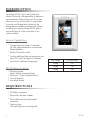
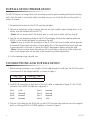
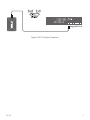
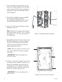
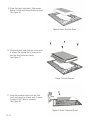
In-Wall Control Mount for iPod Touch
INTRODUCTION
The Mirage KP-iOS is an in-wall system that
allows iPod touch® (4th generation) to become a
semi-permanent fixture in your wall. The system
allows you to use an iPod touch as a key panel
to control your Mirage Audio System via the
Mirage App and wireless communication. Before
installing and using the Mirage KP-iOS, please
read and follow all of the instructions in this
manual carefully.
System Capabilities:
* Charges iPod touch while it is mounted
via Cat5 cable connected to an Autonomic
Mirage Amplifier.
* Mounts iPod touch in-wall.
* Provides additional long distance power only
up to 200’ using 18 awg wire if required.
* See chart for additional wiring specs.
KP-iOS Box Contents
1.Mounting System
(bezel, retainer, mounting frame)
1.Electronics: 30-pin Connector Board
1.Cut-Out Template
1.Instruction Manual
Wire Gauge
22awg
20awg
18awg
Distance (Feet)
75
120
200
Required Tools
* #2 Phillips screwdriver
* Wire cutters and wire strippers
* RJ-45 cable crimp tool and modular
connectors
* Sheet rock saw
(for retrofitting into an existing wall)
2
KP-iOS
Selecting an Installation Location
The KP-iOS is designed for use in normal interior environments. When selecting an installation location
please consider the following:
* Do not use the KP-iOS outside or in a humid or wet environment. It is not waterproof or water-resistant.
* The KP-iOS cut-out must have enough depth within the wall cavity for the KP-iOS and its connections.
* The KP-iOS has screw mounting holes on both sides that allow it to be installed up against a stud.
* Check for a strong Wi-Fi signal at the mounting location using the iPod touch that is to be installed in
the KP-iOS.
Control Mount Rear Connections
Mirage Amplifier: RJ-45 jack connects to a Mirage Amplifier via Cat5 cable. The Cat5 cable receives DC power
from the Mirage Amplifier.
Wiring Cat5/RJ-45 Cable
The Cat5 cable and RJ-45 connector used in iPort installations must be wired according to the
T568A (Straight-Through) Standard with cables wired identically at both ends.
To prepare the Cat5 cable and RJ-45 connector for KP-iOS installation:
1. Pull the Cat5 wire through the wall between the desired locations.
2. Use a stripper or knife to strip about 1” of the cable jacket off each end of the wire.
- Be careful not to nick any of the individual wires.
3. Untwist the wire pairs and spread them flat. Arrange them as shown in Figure 2.
4. Trim the ends of the individual wires to ½” in length, making sure that they are even with each other. Flatten
the wires against each other, leaving no space between them.
5. Hold the RJ-45 connector clip-side down and
insert the Cat5 wire ends firmly into the connector. Make sure that all the wires are flat all the
way to the very front of the connector.
6. Re-confirm that the color orientation matches
the diagram and that cable jacket fits against the
connector stop.
7. Firmly crimp the RJ-45 connector with the crimp
tool. Confirm that the connector is crimped firmly
and that all the wires are flat right up against the
front of the connector. If even one of these wires
are incorrect, cut the connector off the cable and
repeat steps 2 – 7 with a new RJ-45 connector.
Figure 2: RJ-45 Connector
KP-iOS
3
Installation Preparation
The KP-iOS features an integral Roto-Lock mounting system for quick mounting directly into existing
walls. Once the hole is cut and the cables have been run, you can install the iPort into the wall in a
matter of seconds.
1.Determine the location for the KP-iOS and the wall plate.
2.Perform an obstruction survey to ensure there are no studs, conduit, pipes, heating ducts, or air
returns that will interfere with the KP-iOS.
- Note: You can mount the KP-iOS directly next to a wall stud on either side (see Step 8).
3.Find the cut-out template provided in the KP-iOS packaging. Position the template where the
KP-iOS is to be located and pencil an outline on the wall.
- Note: Be sure to confirm the installation of the KP-iOS at this time for either vertical (portrait)
or horizontal (landscape) orientation. Certain applications of the mounted iPod touch work only
in one orientation, so be sure to confirm the client’s requirements before cutting the hole.
- Note: If you are unsure about obstructions, drill a small hole in the center of the outline and
insert a coat hanger wire into the hole to feel around for possible obstructions.
4.Cut the opening using a drywall saw.
Connections and Installation
1.Before making connections, run a length of Cat5 cable through the wall from the KP-iOS location
to the location of the Mirage Amplifier, as shown in Figure 3.
Wire Type
Cat5
Distance (Feet)
100
2.Install RJ-45 connectors on both ends of the Cat5 cable as explained in Figure 2: Cat5 / RJ-45
connector. The Cat5/RJ-45 cable pin assignment is:
Pin
Pin
Pin
Pin
1:
2:
3:
4:
+12v
Ground
Unused
Unused
Pin
Pin
Pin
Pin
5:
6:
7:
8:
Unused
Unused
Ground
+12v
3.Plug the Cat5 cable into the RJ-45 jack on the KP-iOS and the other end into one of the keypad
ports on a Mirage M-400 or M-800 amplifier, as shown in Figure 3.
4
KP-iOS
POWER
WIRELESS
INTERNET
ETHERNET PORT
1
2
3
4
M-800
MIRAGE 8 ROOM
DIGITAL AMPLIFIER
Keypad Ports
Figure 3: KP-iOS System Connection
KP-iOS
5
4.Prior to placing the mounting frame into the
wall, pull a sufficient length of the Cat5 cable
and its attached RJ-45 connector through the
opening in the top of the mounting frame, as
shown in figure 4.
5.The retainer and bezel are pre-assembled
with internal packaging materials.
Disassemble by removing the four screws.
Discard the foam block and card insert.
6.Insert the KP-iOS mounting frame into the
opening in the wall.
Note: The Roto-Lock system can accommodate wall thickness of 3/8” to 3/4” and can
be extended to 1 1/4” with the removal of
the toggle caps.
Figure 4: Mounting Cradle Installation
7.Hand-tighten the four Roto-Lock screws on the
KP-iOS mounting frame as shown in Figure 5.
The Roto-Lock clamps will automatically
rotate into position behind the wall and
begin clamping the mount.
- Note: When you notice resistance on the
four screws, the KP-iOS has been clamped
successfully.
- Important: Never over-tighten the
Roto-Lock screws.
8.If there is a wall stud up against one side of
the utility box that prevents one Roto-Lock
clamp from operating, secure the box by
hand-driving a 1½” #6 drywall screw (not
provided) through the hole on that side of
the chassis and into the wall stud.
- Important: Do not over-tighten the
drywall screw.
Figure 5: Roto-Lock Screw Locations
6
KP-iOS
9.Place iPod touch into bezel. Align power
button on iPod with Power Button on bezel.
(See Figure 6)
Figure 6: Insert iPod into Bezel
10.Place back plate over iPod and secure with
4 screws. The retainer has a foam pad to
hold the iPod touch very securly.
(See Figure 7)
Figure 7: Attach Retainer
11.Place the connector board into the iPod
touch and secure to retainer with 2 screws.
Connect RJ-45 Cable to connector.
(See Figure 8).
Figure 8: Attach Connector Board
KP-iOS
7
12.Attach the assembly to the mounting frame
as shown in Figure 9.
Note: To sync your iPod touch with your
computer, please follow the steps above in
reverse order to remove the iPod touch and
sync. Once your synchronization is complete,
reinstall the iPod touch and follow the steps to
reassemble.
Figure 9: Attaching Assembly
8
KP-iOS
Operation
Once the KP-iOS is installed, the iPod
touch is now fully functional.
POWER BUTTON
Use the iPod touch screen to choose: home
screen, applications, music, email.
A power on/off button is located on the edge of
the KP-iOS bezel as noted in figure 10.
Note: For questions regarding the touchscreen
functions of your iPod touch, please visit:
www.apple.com
Figure 10: Bezel
KP-iOS
9
Specifications
5V 1A DC, regulated
Dimensions (W x H x D).......................................
4 .027” x 5.969” x 2.4”
(102.29mm x 151.61mm x 60.9mm)
Cut-out Dimensions (W x H)................................
3.42” x 5 .34”
(86.87mm x 135.64mm)
151.61mm
5.969in
Power..................................................................
10
55.62mm
2.190in
60.96mm
2.400in
102.29mm
4.027in
KP-iOS
LIMITED ONE (1) YEAR WARRANTY
AUTONOMIC warrants to the first end-user purchaser that this AUTONOMIC-Brand product (“Product”), when purchased from and
installed by an authorized AUTONOMIC Dealer/Distributor, will be free from defective workmanship and materials in the initial installation
for the period stated below. AUTONOMIC will at its option and expense during the warranty period, either repair the defect or replace the
Product with a new or remanufactured Product or a reasonable equivalent at no charge for parts, labor and return shipping.
EXCLUSIONS
TO THE EXTENT PERMITTED BY LAW, THE WARRANTY SET FORTH ABOVE IS IN LIEU OF, AND EXCLUSIVE OF, ALL OTHER WARRANTIES,
EXPRESS OR IMPLIED, AND IS THE SOLE AND EXCLUSIVE WARRANTY PROVIDED BY AUTONOMIC. ALL OTHER EXPRESS AND IMPLIED
WARRANTIES, INCLUDING THE IMPLIED WARRANTY OF MERCHANTABILITY, IMPLIED WARRANTY OF FITNESS FOR USE, AND IMPLIED
WARRANTY OF FITNESS FOR A PARTICULAR PURPOSE ARE SPECIFICALLY EXCLUDED. No one is authorized to make or modify any
warranties on behalf of AUTONOMIC.
The warranty stated above is the sole and exclusive remedy and AUTONOMIC’s performance shall constitute full and final satisfaction of all obligations, liabilities and claims with respect to the Product. IN ANY EVENT, AUTONOMIC SHALL NOT BE LIABLE FOR
CONSEQUENTIAL, INCIDENTAL, ECONOMIC, PROPERTY, BODILY INJURY, OR PERSONAL INJURY DAMAGES ARISING FROM THE
PRODUCT, ANY BREACH OF THIS WARRANTY OR OTHERWISE.
This warranty statement gives you specific legal rights, and you may have other rights which vary from state to state. Some states do
not allow the exclusion of implied warranties or limitations of remedies, so the above exclusions and limitations may not apply. If your
state does not allow disclaimer of implied warranties, the duration of such implied warranties is limited to the period of AUTONOMIC’s
express warranty.
Your Product Model and Description: MIRAGE KP-iOS
Warranty Period for this Product: One (1) year from the date on the original sales receipt, invoice or other satisfactory proof of purchase.
Additional limitations and Exclusions From Warranty Coverage: The warranty described above is non-transferable, and does not
include damage to allied or associated equipment which may result for any reason from use with this Product, and does not include
Product failure caused by accident, disaster, negligence, improper installation, misuse (e.g. over driving the amplifier or speaker,
excessive heat or cold or humidity, outdoor installation), or from service or repair which has not been authorized by AUTONOMIC.
Obtaining Authorized Service: If you purchased your AUTONOMIC from an AUTONOMIC Dealer, you (1) must contact your authorized
AUTONOMIC Dealer/Installer or call AUTONOMIC Customer Service at 914-598-1647, Option 2 within the warranty period, (2) must
obtain a return merchandise number (RMA), and (3) deliver the Product to AUTONOMIC shipping prepaid during the warranty period,
together with the original sales receipt, invoice or other satisfactory proof of purchase from your AUTONOMIC Dealer. If you did not
purchase from an iPort dealer, you must contact your authorized seller within the warranty period and obtain instructions for obtaining
authorized service.
KP-iOS
11
914 598 1647 | www.Autonomic-Controls.com
©2012 Autonomic Controls and Dana Innovations. All rights reserved. Autonomic, iPort, and Roto-Lock
are registered trademarks of Autonomic and Dana Innovations. iPod is a trademark of Apple Inc. “Made
for iPod” means that an electronic accessory has been designed to connect specifically to iPod and has
been certified by the developer to meet Apple performance standards. Apple is not responsible for the
operation of this device or its compliance with safety and regulatory standards. Please note that the use
of this accessory with iPod may affect wireless performance. Due to continuous product improvement, all
specifications are subject to change without notice.
33-5843
12-2012