1
User's Manual
LINE THERMAL PRINTER
MODEL
CBM-262
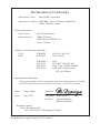
Declaration of Conformity
: Japan CBM Corporation
Manufacturer’s Name
Manufacturer’s Address : CBM Bldg., 5-68-10, Nakano, Nakano-ku
Tokyo, 164-0001, Japan
Declare the Product
Product Name
Line Thermal Printer
Model Number(s)
CBM-262 Series
(CBM-262-R, CBM-262-P)
(S.No. 1001001 - )
Conform to the following Standards
LVD
EMC
:EN60950
:EN55022
:1992+A1+A2:1993
:1995 Class B
:EN50082-1
:IEC801-2
:IEC801-3
:IEC801-4
:1992
:1991 4KV CD, 8KV AD
:1984 3V/m, 27MHz-500MHz
:1988 0.5KV (Signal Line)
1KV (AC Mains)
Supplementary Information
“The product complies with the requirements of the Low Voltage Directive 73/23/EEC,
93/68/EEC and the Directive 89/336/EEC, 91/263/EEC, 92/31/EEC, 93/68/EEC”
Place:
Tokyo, Japan
Signature:
Date:
April, 1997
Full Name: Mikio Moriya
Position:
General Manager
R&D Department
European Contact:
Norco Declaration AB
Box 7146 S-250 07 Helsingborg. Sweden
This declaration is applied only for 230V model.
Cautions
1. Please read this user's manual thoroughly before attempting to use this printer. After reading, keep this manual in a secure place where it can be referred to easily if necessary.
2. The contents of this user's manual are subject to partial modification without prior notice.
3. Transfer of the contents of this user's manual, either in part or in whole, without permission is strictly prohibited.
4. Do not attempt maintenance, disassembly or repairs of any parts of this printer except as
indicated in this user's manual.
5. This company shall not be responsible for damages caused by improper operation or handling of this printer by the customer, or caused by the operating environment.
6. Do not attempt any operations which are not described in this user's manual. doing so
could cause an accident or breakdown.
7. Data, etc. are basically temporary, and cannot be stored or preserved for extended periods
or permanently by this printer. This company shall not be liable in any way for damages of
loss of profits, etc. resulting from loss of data due to breakdown, repairs or inspections,
etc. Please understand this point in advance.
8. If you find any points in these materials which are uncertain, are misprinted or are missing,
please notify this company.
9. Please note that this company shall not be liable for any influence which may effect operation of this printer arising from 8 items above.
FCC COMPLIANCE STATEMENT
FOR AMERICA USERS
This equipment has been tested and found to comply with the limits for a Class A digital
device, pursuant to Part 15 of the FCC Rules. These limits are designed to provide reasonable protection against harmful interference when the equipment is operated in a commercial environment. This equipment generates, uses, and can radiate radio frequency energy
and, if not installed and used in accordance with the instruction manual, may cause harmful interference to radio communications. Operation of this equipment in a residential area
is likely to cause harmful interference in which case the user will be required to correct the
interference at his own expense.
EMI COMPLIANCE STATEMENT FOR
CANADIAN USERS
This equipment generates and uses radio frequency energy and if not installed and used
properly, that is, in strict accordance with the manufacturer’s instructions, may cause interference to radio and television reception. This digital apparatus does not exceed the
Class A limits for radio noise emissions from digital apparatus set out in the Radio Interference Regulations of the Canadian Department of Communications. This equipment is
designed to provide reasonable protection against such interference in a residential installation. However, there is no guarantee that interference will not occur in a particular installation. If this equipment does cause interference to radio or television reception, which can
be determined by turning the equipment off and on, the user is encouraged to try to correct
the interference by one or more of the following measures:
•
•
•
•
Reorient or relocate the receiving antenna.
Increase the separation between the equipment and receiver.
Connect the equipment into an outlet on a circuit different from that to which the
receiver is connected.
Consult the dealer or an experienced radio/TV technician for help.
CAUTION:
Use shielded cables to connect this device to computers.
Any changes or modifications not expressly approved by the grantee of this device could
void the use’s authority to operate the equipment.
ETAT DE CONFORMITE EMI A L’USAGE
DES UTILISATEURS CANADIENS
Cet équipment produit et utilise l’énergie à radiofréquences et s’il n’est pas installé et
utilisé correctment, c’est à dire en accord strict avec les instructions du fabricant, il risque
de provoquer des intérferences avec la réception de la radio et de la télévision.
Le présent appareil numérique n’émet pas de bruite radioélectriques dépassant les limites
applicables aux appareils numériques de la classe A prescrites dans le Réglement sur le
brouillage radioélectrique édicté par le ministère des Communications du Canada.
Cet équipment est conçu pour fournir une protection satisfaisante contre de telles
interférences dans une installation résidentielle. Cependant, il n’y a pas de garantie contre
les interférences avec les réceptions radio ou télévision, provoquées par la mise en et hors
circuit de l’équipment; aussi, il est demandé a l’utilisateur d’essayer de corriger l’interférence
par l’une ou plus des mesures suivantes:
•
•
•
Réorienter l’antenne de réception.
Installer l’ordinateur autre part, par égard pour le récepteur.
Brancher l’ordinateur dans une prise de courant différente de façon à ce que
l’ordinateur et le récepteur soient branchés sur des circuits différents.
Important Safety Instructions
1. Read all of these instructions and save them for later reference.
2. Follow all warnings and instructions marked on the product.
3. Unplug this product from the wall outlet before cleaning. Do not use liquid or aerosol
cleaners. Use a damp cloth for cleaning.
4. Do not use this product near water.
5. Do not place this product on an unstable cart, stand or table. The product may fall, causing
serious damage to the product.
6. Slots and openings on the cabinet and the back or bottom are provided for ventilation.
To ensure reliable operation of the product and to protect it from overheating, do not block
or cover these openings. The openings should never be blocked by placing the product on
a bed, sofa, rug or other similar surface. This product should never be placed near or over
a radiator or heat register. This product should not be placed in a built-in installation unless
proper ventilation is provided.
7. This product should be operated from the type of power source indicated on the marking
label. If you are not sure of the type of power available, consult your dealer or local power
company.
8. This product is equipped with a 3-wire grounding-type plug, a plug having a third (grounding) pin. This plug will only fit into a grounding-type power outlet. This is a safety feature.
If you are unable to insert the plug into the outlet, contact your electrician to replace your
obsolete outlet. Do not defeat the safety purpose of the grounding-type plug.
9. Do not allow anything to rest on the power cord. Do not locate this product where cord will
be walked on.
10. If an extension cord is used with this product, make sure that the total of the ampere ratings
on the products plugged into the extension cord do not exceed the extension cord ampere
rating. Also, make sure that the total of all products plugged into the wall outlet does not
exceed 15 amperes.
11. Never push objects of any kind into this product through cabinet slots as they may touch
dangerous voltage points or short out parts that could result in a risk of fire or electric
shock. Never spill liquid of any kind on the product.
12. Except as explained elsewhere in this manual, don’t attempt to service this product yourself. Opening and removing those covers that are marked “Do Not Remove” may expose
you to dangerous voltage points or other risks. Refer all servicing on those compartments
to service personnel.
13. Unplug this product from the wall outlet and refer servicing to qualified service personnel
under the following conditions:
A. When the power cord or plug is damaged or frayed.
B. If liquid has been spilled into the product.
C. If the product has been exposed to rain or water.
D. If the product does not operate normally when the operating instructions are followed.
Adjust only those controls that are covered by the operating instructions since improper adjustment of other controls may result in damage and will often require extensive work by a qualified technician to restore the product to normal operation.
E. If the product has been dropped or the cabinet has been damaged.
F. If the product exhibits a distinct change in performance, indicating a need for service.
Cautions for Safety
The following items are included in this manual to point out precautions that must be
taken in order to prevent injury to the user or other persons or damage to property.
• The degree of injury or damage caused by improper operation without heeding
the warnings given herein is described as follows.
Warning
This indicates contents in which improper operation of this
product without heeding the warnings given may lead to death
or severe injury.
Caution
This indicates contents in which improper operation of this
product without heeding the cautions given may lead to personal injury or physical damage.
This icon is displayed for items where the user is urged to exercise caution.
i
This icon is displayed to point out information on how to do important tasks, etc.
Warning
Doing the following actions may cause damage to this product or cause it to break
down, overheat, and could also cause fire or electric shock, so by all means do
not do them.
If there is damage or breakdown, switch off the power and pull the plug out of
the outlet. Contact your dealer immediately.
• Do not step on, drop, hit or otherwise apply a strong impact to the printer.
• Do not install this product in a place with poor ventilation and do not use it with its air
vent blocked.
• Do not install this product in a place such as a research laboratory where there are
chemical reactions, and do not install it in a place where there is salt or gas in the air.
• Do not use this product at a voltage and frequency other than the specified voltage
and frequency.
• Do not disconnect the power cord or data cable by grasping the cable, and do not pull
on this product while a heavy weight is bearing on the cables or attempt to carry it by
holding the cables.
• Do not drop or poke foreign objects such as paper clips, straight pins, etc. inside this
product.
• Do not plug this product into a heavily loaded circuit.
• Do not spill drinks such as tea, coffee or juice on this product, or spray it with insecticides. If water or other liquid is spilled on it by accident, switch off the power immediately and disconnect the power plug from the outlet, then contact your dealer.
• Do not attempt to disassemble or modify this product. It could cause fire or electric
shock.
Keep the plastic bag used to pack this product out of the reach of children so they
cannot smother themselves with it, or dispose of it promptly. If they pull it over
their head, there is danger of them suffocating to death.
Cautions for Installation
• Do not use or store this product in a place where there is fire or water vapor, where it
will be exposed to direct sunlight, in a place where it will be exposed to heat or
humidity conditions that it was not specified for, such as next to a heater or burner, or
a place where there is a lot of oil, iron filings, dust or dirt, etc. Doing so could cause
it to break down, emit smoke or catch fire.
• Do not install this product in a place such as an experimental laboratory where there
are chemical reactions taking place, or where there is salt or gas in the air. This could
cause fire or electric shock.
• Install on a level, stable table which doesn't vibrate, in a location where there is good
ventilation. (Do not cover the air holes.)
• Do not place any articles on top of the printer. It could cause it to break down.
• Do not use this printer near, or plug it into the same outlet with, a radio or television
receiver. Doing so could interfere with reception.
• Do not use this product at a voltage and frequency other than the specified voltage
and frequency.
• Make sure the circuit where this printer is plugged in has sufficient surplus capacity to
operate this printer without trouble.
• Avoid attaching this printer's power cord to an overloaded electric circuit. If the circuit
is overloaded, it could cause the electric line to overheat and cause a fire, or trip the
circuit breaker. Also, do not walk on the power cable or place objects on top of it.
• When disconnecting cables, always switch off the power first, then take hold of the
plug or connector and disconnect them. Do not pull on this product while a heavy
weight is bearing on the cables or attempt to carry it by holding the cables.
• Connect the cable connectors securely. Particularly, if the cables are connected with
the polarity reversed, it could destroy the internal components, and also have a bad
effect on the device on the other end of the cable.
• In order to avoid garbling of data, etc. due to noise, always use shielded signal lines
or twisted pair lines. Also, please avoid connecting this printer with a device that
generates a lot of noise.
• Use this printer in a place where it is near to an outlet, and the power plug can be
pulled out easily, and under conditions where the power supply can be cut off easily.
Cautions for Handling
The following methods of handling may lead to breakdown, so please do not use this
printer by these methods.
• Do not attempt to print without paper being set in the printer.
• Be careful not to let paper clips, straight pins, screws or other foreign objects fall
inside the printer.
• Do not spill any liquids on this product, or let it absorb any chemicals.
• Do not subject this product to a strong impact, such as stepping on it, dropping it or
hitting it.
• Never attempt to operate the operation panel using a sharp object such as the point
of a pen.
• Do not tape sheets of paper using cellophane tape, etc. and try to print continuously.
• Do not pull hard on the paper once it is set in the printer.
To avoid injury and extended damage,
• Do not touch the printing unit on the print head.
• While the power is on, do not touch the printer's internal cutter, gears or other moving
parts, or electrical components with bare hands.
• Be careful not to injure yourself or damage other objects by the edges of metal panels, etc.
• If anything abnormal occurs during operation, stop use immediately and pull the power
plug out of the outlet.
• When the printer breaks down, contact your service man. Do not attempt to disassemble the printer yourself.
i
Daily Maintenance
• When carrying out routine maintenance, always be sure to disconnect the power.
• When cleaning the platen, dampen a cloth with ethyl alcohol and wipe off the dust,
etc.
• Wipe off dirt, dust, etc. from the printer's case using a dry, soft cloth. If extremely
dirty, wipe it off with a cloth dipped in water and thorough wrung out. Never use
alcohol, paint thinner, trichloroethylene, benzene or ketone based organic solvents,
or a chemical cleaning rag.
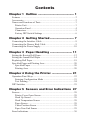
Contents
Chapter 1 Outline ....................................... 1
Features ............................................................................................ 2
Accessories ....................................................................................... 2
Names and Functions of Parts .......................................................... 3
Printer Unit .................................................................................. 3
Operation Panel ........................................................................... 4
Connectors ................................................................................... 5
Factory DIP Switch Settings ....................................................... 6
Chapter 2 Getting Started .......................... 7
Connecting the Interface Cable ........................................................ 8
Connecting the Drawer Kick Cable .................................................. 9
Connecting the Power Supply ........................................................ 10
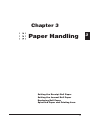
Chapter 3 Paper Handling ........................ 11
Setting the Receipt Roll Paper ........................................................ 12
Setting the Journal Roll Paper ........................................................ 14
Replacing Roll Paper ...................................................................... 18
Specified Paper and Printing Area ................................................. 20
Specified Paper .......................................................................... 20
Printing Area ............................................................................. 20
Chapter 4 Using the Printer ...................... 21
Operation Panel Keys ..................................................................... 22
Entering Configuration Mode ................................................... 23
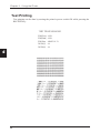
Test Printing .............................................................................. 24
DIP Switches .................................................................................. 25
Chapter 5 Sensors and Error Indications 27
Sensors ............................................................................................ 28
Printer Cover Open Sensor ........................................................ 28
Head Up Sensor ......................................................................... 28
Head Temperature Sensor ......................................................... 28
Paper Sensor .............................................................................. 28
Cutter Position Sensor ............................................................... 28
Paper Near End Sensor .............................................................. 29
Error Indications ............................................................................. 30
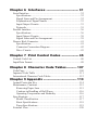
Chapter 6 Interfaces ................................ 31
Serial Interface ............................................................................... 32
Specifications ............................................................................ 32
Signal Lines and Pin Arrangement ............................................ 32
Explanation of Signal Names .................................................... 33
Input/Output Circuits ................................................................. 33
Protocols .................................................................................... 35
Parallel Interface ............................................................................. 36
Specifications ............................................................................ 36
Input/Output Circuits ................................................................. 38
Signal Lines and Pin Arrangement ............................................ 39
Drawer Kick Connector .................................................................. 41
Specifications ............................................................................ 41
Connector Connection Diagram ................................................ 42
Drive Circuits ............................................................................ 43
Chapter 7 Print Control Codes ................. 45
Control Code List ........................................................................... 46
Input Data Format .......................................................................... 49
Chapter 8 Character Code Tables.......... 107
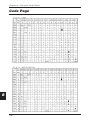
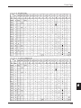
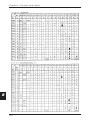
Code Page ..................................................................................... 108
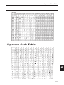
Japanese Code Table .................................................................... 111
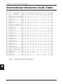
International Character Code Tables ............................................ 112
Chapter 9 Appendix ................................. 113
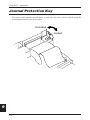
Journal Protection Key ................................................................. 114
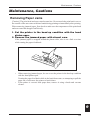
Maintenance, Cautions ................................................................. 115
Removing Paper Jams ............................................................. 115
Cautions in Handling of Roll Paper ........................................ 116
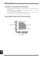
Operating Temperature and Humidity .................................... 116
Specifications ............................................................................... 117
Model Classification ............................................................... 117
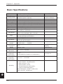
Basic Specifications ................................................................ 118
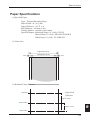
Paper Specifications ................................................................ 119
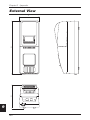
External View ............................................................................... 120
1
Chapter 1
Outline
This printer is a tandem type 2-station line thermal
printer which accepts 58 mm wide paper, developed
for use in PC-POS/ECR terminals and all types of data
communications terminals, etc.
Features
Accessories
Names and Functions of Parts
1
Chapter 1 Outline
1
Features
•
•
•
•
•
•
•
•
Compact design with the two rolls of paper set front to back to keep the printer's
width narrow.
Power switch and operation panel are located on the front, and cable connections
are made in an indented part, giving it a shape without projictions on the sides and
rear, which makes installation easy.
The thermal line head reduces noise and achieves high speed printing at 62.5 mm/
sec.
An auto cutter is standard equipment in the receipt printer.
Simple controls which conform to ESC/POSTM.
Drawer control is enabled using the drawer kick interface.
Paper setting chore is simplified by the roll drop-in type auto loading feature.
A coin tray, magnet plate and writing table are standard equipment.
Accessories
Standard Specifications (without Journal Protection Key)
•
•
•
•
Roll Paper x 2
Adapter x 1
Power Cord x 1
User's manual x 1
Optional Specifications (with Journal Protection Key)
•
•
•
•
•
Roll Paper x 2
Adapter x 1
Power Cord x 1
User's manual x 1
Journal Protection Key x 1
[NOTE]
2
Japan CBM Corp., Type 26AD-U Adapter is provided for use in the United
Stated and Canada.
Japan CBM Corp., Type 26AD-E Adapter is provided for use in Europe.
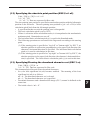
Names and Functions of Parts
1
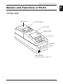
Names and Functions of Parts
Printer Unit
Rear Cover
Journal Window
Front Cover
Magnet Plate
Coin Tray
Operation
Panel
Power Switch.
(Turns the power on and off.)
3
Chapter 1 Outline
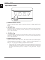
Operation Panel
1
1
2
3
4
1 POWER Indicator (Green)
Lights up when the power switch is turned on and power is being supplied to the
printer.
2 RECEIPT Key
Feeds receipt paper. Pressing once causes the paper to advance one line, based on the
amount for a carriage return set previously. If the key is pressed continuously, the
paper is fed continuously.
3 JOURNAL Key
Feeds journal paper. Pressing once causes the paper to advance one line, based on the
amount for a carriage return set previously. If the key is pressed continuously, the
paper is fed continuously.
4 ERROR Indicator (Orange)
Lights up or blinks when an error occurs. The content of the error is indicated by the
indicator lighting up or blinking (see “Chapter 5 - Sensors and Error Indications,” on
page 30). Goes off when the printer's condition returns to normal.
•
4
When the RECEIPT key and JOURNAL key are pressed separately, or are pressed
together when the power is switched on, it is possible to enter the test printing and
the printer internal setting mode (see “Chapter 4 - Using the Printer,” on pages
21~24).
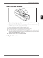
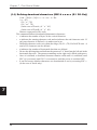
Names and Functions of Parts
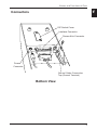
Connectors
1
DIP Switch Cover
Interface Connector
Drawer Kick Connector
Power
Connector
Ground Cable Connection
Tap (Ground Terminal)
Bottom View
5
Chapter 1 Outline
Factory DIP Switch Settings
1
ON
ON
1 2 3 4 5 6 7 8
1 2 3 4
DIP Switch 1
DIP Switch 2
The above switches are shown in the OFF position.
•
6
DIP switch 2 is used for the serial interface only. (See “Chapter 4 - Using the
Printer,” on pages 25 and 26).
2
Chapter 2
Getting Started
•
•
After all the connections are completed, insert the
power cord plug in the receptacle.
When redoing connections, be sure to turn off the
power to the printer main unit and the terminal first.
Connecting the Interface Cable
Connecting the Drawer Kick Cable
Connecting the Power Supply
7
Chapter 2 Getting Started
1
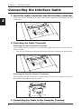
Connecting the Interface Cable
1. Insert the cable's connector into the interface connector.
Align the top and bottom of the male and female connectors and connect the two
connectors.
2
2. Fastening the Cable Terminals
Fastening the Serial Interface Connector:
After making sure the connector is inserted fully, tighten the screws to fasten the connector in place.
• Use screws which can be tightened by hand to fasten the connector to the interface.
Fastening the Parallel Interface Connector:
After making sure the connector is inserted fully, turn the wire clamps in the arrow
direction to fasten the connector in place.
3. Connecting the Cable to the Computer Terminal.
Be sure to turn off the power to the computer first, then make connections.
8
Connecting the Drawer Kick Cable
Connecting the Drawer Kick Cable
Connect the drawer kick cable to the drawer kick connector.
Align the top and bottom of the cable connector and the drawer kick connector, then
insert the connector until it makes a clicking sound.
Connect the drawer ground wire to the ground terminal with a
screw.
•
•
Do not connect the connector for any other drawer (solenoid) to the drawer kick
connector than that specified.
Use a M3 X 6 self tapping screw to fasten the grand wire.
9
2
Chapter 2 Getting Started
1
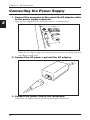
Connecting the Power Supply
1. Connect the connector at the end of the AC adapter cable
to the power supply connector.
Align the top and bottom of the cable and connector to connect them.
2
When the AC adapter's plug is disconnected from the printer, grasp the plug with
your fingers to pull it out.
2. Connect the AC power cord and the AC adapter.
3. Connect the power cord to the receptacle.
Connect the AC adapter with the printer's power supply switched off.
10
Chapter 3
3
Paper Handling
Setting the Receipt Roll Paper
Setting the Journal Roll Paper
Replacing Roll Paper
Specified Paper and Printing Area
11
Chapter 3 Paper Handling
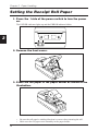
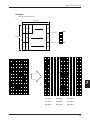
Setting the Receipt Roll Paper
1. Press the I side of the power switch to turn the power
on.
The POWER indicator lights up and the ERROR indicator blinks.
3
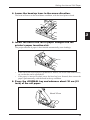
2. Remove the front cover.
3. Place the roll paper in the paper holder as shown in the
illustration.
•
•
12
Be sure the roll paper's winding direction is correct when inserting the roll.
Make sure the roll paper turns smoothly in the paper holder.
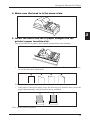
Setting the Receipt Roll Paper
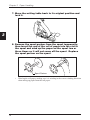
4. Make sure the head is in the down state.
3
5. Insert the end of the roll of paper straight into the
printer's paper insertion slot.
The proper amount of paper is then loaded automatically (auto loading).
•
If the end of the roll of paper is feathered or folded, cut off the end with scissors,
etc. so that the end is squared off.
When operation stops, then setting of the roll paper is completed.
• If the paper is inserted crooked, move the head up lever forward, then correct the
paper's path manually with the head in the up condition.
Next, set the journal roll paper.
13
Chapter 3 Paper Handling
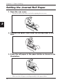
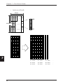
Setting the Journal Roll Paper
1. Open the rear cover.
•
Be sure to remove the front cover before opening the rear cover.
3
2. Remove the spool, then lower the writing table to the
rear.
3. Place the roll paper in the paper holder as shown in the
illustration.
•
•
14
Be sure the roll paper's winding direction is correct when inserting the roll.
Make sure the roll paper is turning smoothly in the paper holder.
Setting the Journal Roll Paper
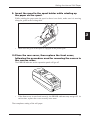
4. Lower the head up lever in the arrow direction.
The head will move to the head down condition, with the head platen closed.
3
5. Insert the end of the roll of paper straight into the
printer's paper insertion slot.
The proper amount of paper is then loaded automatically (auto loading).
•
•
If the end of the roll of paper is feathered or folded, cut off the end with scissors,
etc. so that the end is squared off.
If the paper is inserted crooked, move the head up lever forward, then correct the
paper's path manually with the head in the up condition.
6. Press the JOURNAL key and advance about 30 cm (12
inch) of the roll paper.
About 30 cm
15
Chapter 3 Paper Handling
7. Move the writing table back to its original position and
lock it.
3
8. Remove the spool partner from the spool temporarily,
then insert the end of the roll of paper into the slot in
the spool and wind up the paper on the spool two or
three times so it will not come off the spool. Replace
the spool partner on the spool.
Spool Partner
•
16
Wind up the roll paper, making sure it is winding in the correct winding direction
when taking up paper from the roll paper.
Setting the Journal Roll Paper
9. Insert the spool in the spool holder while winding up
the paper on the spool.
While winding the paper onto the spool so there is no slack, make sure it is moving
along the guide in the writing table.
3
•
Make sure the gear of the spool is engaged in the printer gear.
10.Close the rear cover, then replace the front cover,
following the procedure used for removing the covers in
the reverse order.
The ERROR indicator on the operation panel will go off.
•
If the front cover is not closed securely, the ERROR indicator may not go off. At
such a time, replace the cover securely once more.
That completes setting of the roll paper.
17
Chapter 3 Paper Handling
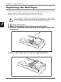
Replacing the Roll Paper
If the amount of roll paper remaining becomes low, the ERROR indicator blinks, reminding the operator that it will soon be time to replace the roll paper.
Printing will stop automatically if the printer runs out of roll paper.
The print head and auto cutter are hot during or immediately
after printing. Please wait until the print head and auto cutter
have cooled sufficiently before replacing the roll paper.
3
1. Remove the cover.
2. Move the head up lever in the arrow direction.
3. Pull the remaining roll paper out of the paper outlet and
remove it.
4. Return the head up lever to its original position.
18
Replacing the Roll Paper
5. Set a new roll of roll paper.
3
•
When replacing the journal roll paper, take out the spool and move the writing
table back, then set the roll paper.
• If the paper is inserted crooked, move the head up lever to move the head to the up
condition, then correct the paper's path manually.
• Remove the finished journal roll paper form the spool.
Follow the procedure below when replacing the journal roll paper.
1. Press the JOURNAL key and wind about 30 cm of paper.
2. Place the roll paper along the guide in the writing table while winding the roll
paper onto the spool, then place the spool in the spool holder (see steps 9 and 10 of
“Setting the Journal Roll Paper” (page 17)).
3. Return the writing table to its original position.
6. Replace the cover.
19
Chapter 3 Paper Handling
Specified Paper and Printing Area
Specified Paper
Type: Specified thermal printing paper.
Paper Width: 58 +0/–1 mm
Paper Thickness: 60~75µ
Roll Diameter: 83 dia. mm or less
Printing Surface: Roll Outside (Surface)
Specified Paper: Mitsubishi Paper Co. (Ltd.) F220VP
Shinoji Paper Co. (Ltd.) PD160R, PD160R-N
Nihon Paper Co. (Ltd.) TF 50KS-E2C
• Print density may differ depending on the paper used. In such cases, please adjust
the print density. (See “Chapter 4 - Using the Printer,” on pages 22 and 23.)
3
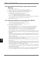
Printing Area
Paper Width 58 mm
2mm
20
Printing Area 54 mm
2mm
Chapter 4
Using the
Printer
4
Settings Using the Operating Buttons
Setting the DIP Switches
21
Chapter 4 Using the Printer
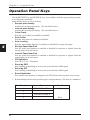
Operation Panel Keys
Use the RECEIPT key and JOURNAL key, in accordance with the query printing system,
to set the printer internally.
Items which can be set are as follows.
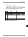
• Receipt print density.
Adjusts the receipt print density. (See the table below.)
• Journal print density.
Adjusts the journal print density. (See the table below.)
• Cover Open
Sets the cover sensor on enabled or disabled.
• Auto Cutter
Sets the auto cutter on enabled or disabled.
• Auto Loading
Sets the auto loading function on enabled or disabled for setting roll paper.
• Receipt Paper Near End
Sets the print stop function on enabled or disabled in response to signals from the
receipt paper near end sensor.
• Journal Paper Near End
Sets the print stop function on enabled or disabled in response to signals from the
journal paper near end sensor.
• CR Operation
Sets CR+LF / LF / Disregard.
• Reset by DSR
Sets enabling or disabling of reset by the serial interface DSR signal.
• Reset by INIT
Sets enabling or disabling of reset by the serial interface INIT signal.
• Error Handshake
Sets whether the interface is changed to the BUSYstate when a printer error occurs.
4
*
Relationship between each specified paper and print density (Use this as a standard.)
Print Density Level
Paper
1
TF50KS-E2c, F220vp.
Condition
Light
2
3
4
22
PD160R, PD160R-N
Dark
Operation Panel Keys
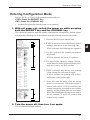
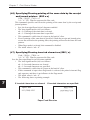
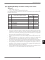
Entering Configuration Mode
Select YES (R) or NO (J) to the printed question and set it.
If YES: Press the RECEIPT key.
If NO: Press the JOURNAL key.
• Perform the operation with the front cover removed.
1. With roll paper set, switch the power on while pressing
both the RECEIPT key and the JOURNAL key.
This causes the printer to enter the printer configuration setting mode, and the printer
will print the following text in accordance with the selected menu for each item.
1. Prints the ROM version and the date.
PRINTER SETTING MODE
YES:Push (R)eceipt Key
NO :Push (J)ournal Key
ROM(Even):AW32-0A0A
ROM(Odd) :AW33-0A0A
ROM Date :MAY-28-1996
Reset Current Settings
To Factory Settungs?
Print Current Settings?
1
YES (R) NO (J)
YES (R) NO (J)
2
3
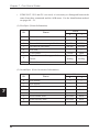
Current Settings
<HARDWARE SETTINGS>
:RECEIPT DENSITY
:JOURNAL DENSITY
:COVER OPEN SENSOR
:AUTO CUTTER
:AUTO LOADING
:R PAPER NEAR END
:J PAPER NEAR END
:CR CONTROL
:KANJI MODE
:RESET BY INIT
:RESET BY DSR
:ERROR HANDSHAKE
:INPUT BUFFER
<CHARACTER SETTINGS>
:CHARACTER TABLE
:COUNTRY
<SERIAL SETTINGS>
:DATA BIT
:PARITY
:PROTOCOL
:BUADRATE
1/2/3/4
1/2/3/4
VALID/INVALID
VALID/INVAILD
VALID/INVALID
VALID/INVAILD
VALID/INVAILD
CR+KF/LF/IGNORE
VALID/INVALID
VALID/INVALID
VALID/INVALID
BUSY/INVALID
8KB/1LINE
PC473/PC850
JAPAN/U.S.A
FRANCE/GERMANY
U.K./DENMARK
SWEDEN/ITALY
SPAIN/NORWAY
DENMARK2/SPAIN2
LATIN/KOREA
LEGAL
8BITS/7BITS
NONE/ODD/EVEN
DTR:DSR
XON:XOFF
9600/4800
2400/19200
Change Current Setting?
:RECEIPT DENSITY
YES(R) NO(J)
1
YES(R) NO(J)
:JOURNAL DENSITY
4
5
6
1
VALID
YES(R) NO(J)
:AUTO LOADING
VALID
YES(R) NO(J)
:R PAPER NEAR END
INVALID
YES(R) NO(J)
:J PAPER NEAR END
INVALID
YES(R) NO(J)
:CR CONTROL
CR+LF
YES(R) NO(J)
:KANJI MODE
INVALID
YES(R) NO(J)
:RESET BY INIT
VALID
YES(R) NO(J)
:RESET BY DSR
VALID
YES(R) NO(J)
:ERROR HANDSHAKE
BUSY
YES(R) NO(J)
Current Settings
:RECEIPT DENSITY
:JOURNAL DENSITY
:COVER OPEN SENSOR
:AUTO CUTTER
:AUTO LOADING
:R PAPER NEAR END
:J PAPER NEAR END
:CR CONTROL
:KANJI MODE
:RESET BY INIT
:RESET BY DSR
:ERROR HANDSHAKE
SETTING MODE END!!
T1/2/3/4
1/2/3/4
VALID/INVALID
VALID/INVALID
VALID/INVALID
VALID/INVALID
VALID/INVALID
CR+LF/LF/IGNORE
VALID/INVALID
VALID/INVALID
VALID/INVALID
BUSY/INVALID
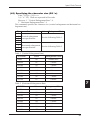
3. If YES is selected, the currently set menues
are printed.
If NO is selected, the line in 5 is printed.
4. The input buffer, character settings (International character code) and serial protocol settings are as set by the DIP switches.
5. If YES is selected, after the line in 6, printing
of the settings for each item is begun.
If NO is selected, the printing of 8 is done,
and setting of the printer ends.
YES(R) NO(J)
:COUVER OPEN SENSOR VALID
YES(R) NO(J)
:AUTO CUTTER
2. If YES is selected, it resets the factory default
settings, then moves to the following line.
If NO is selected, the following line is printed.
7
6. Select NO until the menu of all the setting
items is set as desired. When the content is
correct, select YES. If YES is selected, the
setting contents are recorded in non-volatile
memory and the printer prints the next item.
When Error handshake setting item is ended,
the set contents (7) and 8 are printed, then
printer set up is ended.
8
2. Turn the power off, then turn it on again.
The set contents become enabled.
23
4
Chapter 4 Using the Printer
Test Printing
Test printing can be done by turning the printer's power switch ON while pressing the
RECEIPT key.
TEST PRINTING MODE
ROM(Even)
ROM(Odd)
ROM Date
DIP-SW(1)
DIP-SW(2)
4
24
:XXXX
:XXXX
:MM-DD-YY YY
:00
:00
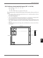
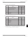
Setting DIP Switches
DIP Switches
DIP switches are located inside the DIP switch cover on the bottom of the printer. Loosen
the screws, then turn the DIP switch cover.
• Turn the power off before setting the DIP switches.
The contents of DIP switches are as shown in the following tables.
DIP Switch 1
No.
(Bold character indicates Factory Default)
Content
1
Serial Interface Data Length
2
Serial Interface Protocol
3
Input Buffer
4
Code Page
OFF
ON
8bits
7bits
DTR/DSR XON/XOFF
8KB
1 Line
PC437
PC850
4
5
6
7
International Characters
See the following table.
8
*
1 and 2 are effective for the serial interface only.
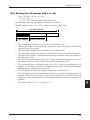
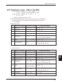
Setting International Characters
SW1-5
SW1-6
SW1-7
SW1-8
International Character Set
OFF
OFF
OFF
OFF
Japanese
OFF
OFF
OFF
ON
U.S.A
OFF
OFF
ON
OFF
French
OFF
OFF
ON
ON
German
OFF
ON
OFF
OFF
U.K
OFF
ON
OFF
ON
Danish
OFF
ON
ON
OFF
Swedish
OFF
ON
ON
ON
Italian
ON
OFF
OFF
OFF
Spanish
ON
OFF
OFF
ON
Norwegian
ON
OFF
ON
OFF
Danish 2
ON
OFF
ON
ON
Spanish 2
ON
ON
OFF
OFF
Latin America
ON
ON
OFF
ON
Korean
ON
ON
ON
OFF
Legal
25
Chapter 4 Using the Printer
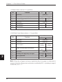
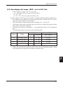
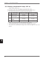
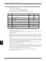
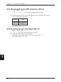
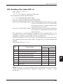
DIP Switch 2
No.
Content
1
2
3
4
(Bold character indicates Factory Default)
OFF
ON
Baud Rate
See Table (1) below.
Parity
See Table (2) below.
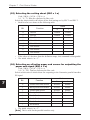
(1) Baud Rate Settings
SW2-2
SW2-1
SW2-4
SW2-3
OFF
OFF
9600
OFF
OFF
No Parity
OFF
ON
4800
OFF
ON
Odd Parity
ON
OFF
2400
ON
OFF
Even Parity
ON
ON
19200
ON
ON
–
4
•
26
Baud Rate Setting
(2) Parity Settings
DIP switch 2 is included only in the case of a Serial interface.
Parity Setting
Chapter 5
Sensors
and
Error Indications
5
This chapter explains the various sensors that this printer
is equipped with and the error indications accompanying them.
Sensors
Error Indications
27
Chapter 5 Sensors and Error Indications
Sensors
Printer Cover Open Sensor
This sensor reacts when the front cover is removed, indicated by the ERROR indicator
(cover open error). Printing is halted.
Head Up Sensor
If the head is moved to the head up position using the head up lever, it is indicated by the
ERROR indicator (Head Up Error.) Printing is halted.
Head Temperature Sensor
To protect the print head from overheating, this sensor functions when the head's temperature becomes high (approximately 60°C (140°F) or higher) and is indicated by the ERROR indicator (Head Overheat). Printing is halted. When the head's temperature drops
(approximately 55°C (131°F) or lower), printing resumes automatically.
Paper Sensor
5
This sensor is located in the paper path of the receipt printer and the journal printer. When
paper is inserted in the printer's paper path, the paper is loaded. If the paper in the paper
path runs out, it is indicated by the ERROR indicator (Paper End Error). Printing is halted.
Cutter Position Sensor
Cutter control is executed by means of the cutter position detection sensor. If detection of
the sensor remains ON or OF for 1 second or longer during cutter motor operation, the
printer judges that the cutter motor is locked and halts further cutter operation and printing
at that point.
28
Sensors
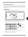
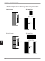
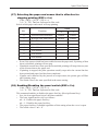
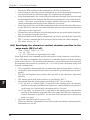
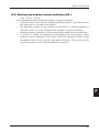
Paper Near End Sensor
This sensor is located on the roll paper holder on the receipt side and the journal side.
When the winding diameter of the roll paper becomes small, it is indicated by the ERROR
indicator. Since the amount of roll paper remaining may differ depending on the thickness
of the winding core, the near end sensor can be set so as to correspond to the thickness of
the winding core.
Setting Method
1. Loosen the adjustment screw holding the sensor lever.
2. Set the top end of the sensor lever on the correct step on the adjustment scale.
Adjustment Screw
Adjustment Scale
#6
Sensor Lever
#1
5
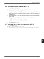
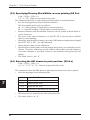
When the specified paper with a winding core whose outer diameter is ø18 mm and
inner diameter is ø12 mm is used, the approximate adjustment scale step are as follows. The factory default setting of the scale is lowest position.
Adjustment Scale Step
Lowest position
Dimension T
Dimension T
Approx. 18.5-20.5 mm
(Paper length: 20-110 cm)
#2
Approx. 20-23 mm
(Paper length: 80-230 cm)
#3
Approx. 25-27.5 mm
(Paper length: 300-480 cm)
*Dimension T = Amount of outer
diameter remaining on roll of
paper.
•
Dimension T, corresponding to the step on the adjustment scale, may vary somewhat.
3. Tighten the adjustment screw and close the sensor lever.
Check if the sensor lever is operating smoothly.
29
Chapter 5 Sensors and Error Indications
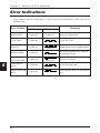
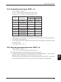
Error Indications
Error contents and error indications, as well as recovery instructions in each case, are as
shown below.
Error Content
5
Indication
POWER LED
ERROR LED
System Error
Lights up.
Cover Open
Lights up.
Head Up
Lights up.
Head Overheat
Lights up.
Paper End or
Paper Near End
Lights up.
Cutter Motor
Lock
Lights up.
(Blinks fast + blinks slow.)
Macro Execution
Wait
Lights up.
(Blinks twice.)
30
Lights up.
(Blinks slowly.)
(Blinks fast.)
Recovery
Recovery impossible.
Close the cover.
Return head up lever to original position.
(Blinks once.)
Recovers automatically when the
temperature drops.
(Blinks once.)
Set new roll paper.
Clear the paper jam.
Press the RECEIPT or JOURNAL
key.
Chapter 6
Interfaces
6
Serial Interface
Parallel Interface
Drawer Kick Connector
31
Chapter 6 Interfaces
Serial Interface
Specifications
Transmission Method
Start-Stop Synchronous Full Duplex Communications
Signal Level
RS-232C
Baud Rate
2400, 4800, 9600, 19200
Data Length
7 or 8 bits
Start Bit
1 bit
Stop Bit
Receiving 1 bit; Transmitting 2 bits or more
Parity
Even, Odd, No Parity
Connector
Printer Side Compatible with DDK 17LE-13250-27
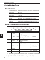
Signal Lines and Pin Arrangement
13
1
25
14
Pin No. Signal Name Direction
1
F.GND
2
TXD
OUT
3
RXD
IN
4
RTS
OUT
6
DSR
IN
7
S.GND
20
DTR
25
INIT
6
•
*1
32
OUT
X-ON/X-OFF
Connects the Host CPU
and printer.
Sends transmission data
and X-ON/X-OFF
signals to the Host CPU
from the printer.
Transmission data from
the Host CPU to the
printer.
Pulls up the signal to
+10V at 3.3k ohms.
DTR/DSR
Not used.
Not used.
Data are sent when the
status information send
signal is “HIGH.”
Always HIGH.
LOW when Busy.
HIGH when Ready.
IN(*1) Printer's Reset signal.
IN indicates a signal from the Host to the printer. OUT indicates a signal from the
printer to the Host.
25pin, INIT is HIGH or the TTL-HIGH level of input (+2V~+15V) .
Serial Interface
Explanation of Signal Names
F. GND (Frame Ground)
Connected to the printer case.
TXD (Transmit Data (Send Data))
Transmission line for sending serial data from the printer to the Host.
RXD (Receive Data)
Transmission line for the printer to receive serial data from the Host.
DSR (Data Set Ready)
Signal line which indicates to the printer that the Host is ready to receive.
A low level reset can be carried out through the menu setting.
S. GND (Signal Ground)
The GND (earth) for the signal line.
DTR (Data Terminal Ready)
Signal line which indicates to the Host that the printer is ready to receive.
RTS (Request To Send)
Pulled up to +10V at 3.3k ohms.
INIT
This is the signal line used by the host to send a reset command to the printer. (However,
this is when enabling of the INIT signal by the menu setting has been selected.)
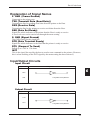
Input/Output Circuits
Input Circuit
Signal Name
Configuration
6
RXD
DSR
Compatible with µPD4721.
Output Circuit
Signal Name
Configuration
TXD
DTR
Compatible with µPD4721.
33
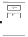
Chapter 6 Interfaces
Reset by DSR
Resets if the voltage becomes -15V ~ -3V.
TRS
Reset by INIT
Resets if the voltage becomes +2V ~ +15V.
TRS
TRS 1ms
6
34
Serial Interface
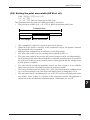
Protocols
X-ON/X-OFF Protocol
Control is by output of the codes for the data transmission request signal X-ON (11 Hex)
and the data transmission stop signal X-OFF (13 Hex). When sending the printer's status
to the Host, this is sent irrespective of the level of the DSR signal.
Conditions for Output of the X-ON Code
•
•
•
When all errors have been cleared.
When the remaining buffer capacity is greater than Non bytes.
After the power is turned on, when in the Ready to Receive state.
Conditions for Output of the X-OFF Code
•
•
When the printer has generated an error and has switched from Online to Offline.
When the remaining buffer capacity is Noff bytes or less.
* Even if the X-ON/X-OFF code output conditions are established, the same code is
not output two times in succession. However, times when the power is turned ON
are expected.
* When the menu setting error handshake is disabled, XON/XOFF is not output
when the error status changes.
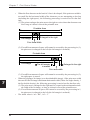
DTR/DSR Protocol
Control is by the level of the DTR signal, Ready “High” /Busy “Low”.
If the printer's status is sent to the Host, it is sent when DSR is “High.” If DSR is “Low,”
the printer waits until it goes “High.”
Conditions for the DTR Signal to become Ready “High”
•
•
•
When all the errors have been cleared.
When the remaining buffer capacity is greater than Non bytes.
After the power is turned on, when in the Ready to Receive state.
Conditions for the DTR Signal to become Busy “Low”
•
•
When the printer has generated an error and has switched from Online to Offline.
When the remaining buffer capacity is Noff bytes or less.
* When the menu setting error handshake is disabled, the DTR signal does not change.
Conditions for Non and Noff (Units: Bytes)
•
•
When there is an 8 KB buffer.
Non=2048
Noff=1024
When there is a one line buffer.
Non= 20
Noff=10
35
6
Chapter 6 Interfaces
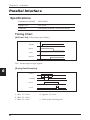
Parallel Interface
Specifications
Transmission Method
8 bit Parallel
Signal Level
TTL Level
Connector
Corresponds to DDK 57RE-40360-803B.
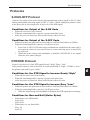
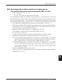
Timing Chart
[At Power On] (If the printer goes Online.)
Power on
*RESET
:
BUSY
:
*ACK
:
SELECT
:
The * means negative logic signals.
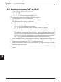
[During Data Reception]
6
DATA1-8
:
*STROBE
:
BUSY
:
*ACK
:
a
b
c
d
a: Min. 0.5 µ Sec*
b: Min. 0.5 µ Sec*
c: Min. 0.5 µ Sec*
36
d: Approx. 2.9 µ Sec
*: Value at the receiving end.
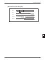
Parallel Interface
[When Receiving the INIT Signal]
1 µSec or longer
*INIT
:
BUSY
:
*ACK
:
*FAULT
:
SELECT
:
Within 200 µ Sec
Level does not change.
Level does not change.
6
37
Chapter 6 Interfaces
Input/Output Circuits
Input Circuit
Signal Name
Configuration
3.3K
DATA1-8
VH=2.0V
VL=0.8V
*INIT
3.3K
CMOS
3.3K
*STROBE
VH=1.8V
100
3.3K
VL=0.9V
1000p
CMOS (Schmidt)
Output Circuit
Signal Name
Configuration
SELECT
*FAULT
*ACK
PE
BUSY
DRAWER KICK STATUS
3.3K
Compatible with 7406.
6
38
Parallel Interface
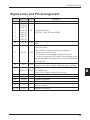
Signal Lines and Pin Arrangement
Pin No. Signal Name Direction
Function
1
*STROBE IN
Synch signal for reading DATA 1-8.
2
DATA1
3
DATA2
4
DATA3
5
DATA4
IN
8-bit parallel data
6
DATA5
(DATA1: LSB, DATA8: MSB)
7
DATA6
8
DATA7
9
DATA8
Data request signal output when ready for receiving
10
*ACK
OUT data.
Goes “Low” when ready to receive data, and “High”
when not ready.
Goes “High” under the following conditions.
11
BUSY
OUT • Printer is in an error state.
• The buffer is full and data cannot be received.
• After receiving the INIT signal, after printing of the
data in the buffer, during the interval until initialization
is completed.
In the case that “Paper End” detection is enabled by the
12
PE
OUT control code, it goes “High” during the paper end state.
Indicates whether the printer is in the Online state or
13
SELECT OUT the Offline state.
Goes “Low” when a printer error occurs.
14
Not used.
15
Not used.
16
GND
Signal line ground.
17
FG
Connected to the printer case.
Connected to +5 V inside the printer. (Cannot be used
18
+5V
by the customer.)
19-30
GND
Signal line ground.
6
39
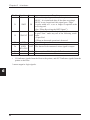
Chapter 6 Interfaces
Pin No. Signal Name Direction
31
*INIT
IN
32
*FAULT
OUT
33
34
35
36
•
GND
DRAWER
KICK
OUT
STATUS
FUSE
OUT
Function
When this signal goes “Low,” the printer becomes
BUSY. It is initialized after all the data are printed.
BUSY is not cleared until this signal goes “High.”
A pulse width of 1 µ sec or longer is required at the
receiving end.
(See “When Receiving the INIT Signal.”)
This signal indicates that the printer is in the error state.
It goes “Low” under any one of the following conditions.
• Paper End
• When an abnormal operation is detected.
Signal line ground.
The drawer kick connector's status signal is output.
Connected to +5 V through a 3.3k ohm resistor.
Not used.
IN indicates signals from the Host to the printer, and OUT indicates signals from the
printer to the Host.
* means negative logic signals.
6
40
Drawer Kick Connector
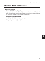
Drawer Kick Connector
Specifications
Drawer Kick Drive Signal
Outputs a pulse signal specified by the ESCp command. Also, the status of SW (+) can be
known from pin 34 of the interface connector in the case of the parallel interface and by the
GSr, for instance command in the case of the serial interface.
Electrical Characteristics
Drive Voltage: DC 24 V
Drive Current: Max. 0.8 A (should be within 510 ms)
SW Signal: Signal level “L”= 0~0.5 V
“H”= 3~5 V
6
41
Chapter 6 Interfaces
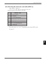
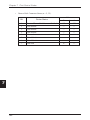
Connector Connection Diagram
NO.
Signal Name
Function
1
FG
Safety ground.
2
DRAWERI
Drawer 1 drive signal.
3
DRSW
Drawer switch input.
4
VDR
Drawer drive power supply.
5
DRAWER2
Drawer 2 drive signal.
6
GND
Common ground in the circuit.
6
1
Connector Used: TM5RJ3-66 (Hirose)
Compatible Connector: Compatible with TM3P-66P (Hirose)
6
•
•
•
•
42
No signals are output during printing.
Both drawers 1 and 2 cannot be driven simultaneously.
Use a 36 ohm or higher drawer solenoid. (Be careful not to let the output current
exceed 0.8A. If the output current exceeds 0.8 A, results cannot be guaranteed.)
The drawer kick connector is not the type used for connections to telephone lines. Do
not connect to any device other than a solenoid.
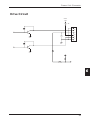
Drawer Kick Connector
Drive Circuit
+24V
1.5A
1
2
3
4
5
6
6
43
Chapter 6 Interfaces
6
44
Chapter 7
Print Control
Codes
7
List of Control Codes
Input Data Format
45
Chapter 7 Print Control Codes
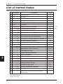
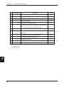
List of Control Codes
Character
Horizontal tab
49
2
LF
Line feed
49
3
CR
Print comand
49
4
FF
Printing in the page mode and return
50
5
CAN
Canceling of print data in the page mode
50
6
RS
Journal tab
50
7
DLE EOT Sending the status in real time
ENQ Real time enquiry to printer
9
ESC FF
10
11
50
54
Printing of data in the page mode
54
SP
Setting the space between characters
55
!
Specifying the print mode all at once
56
12
$
Specifying the absolute print position
57
13
%
Specifying/Clearing the download character set
57
14
&
Defining download characters
58
15
*
Specifying a bit image
61
16
–
Specifying/Clearing underline
63
17
2
Specifying the 1/6 inch line feed amount
63
18
3
Specifying the line feed amount
64
19
=
Controlling data input
65
20
?
Erasing download characters
65
21
@
Printer initialization
66
22
D
Setting the horizontal tab position
66
23
E
Specifying/Clearing bold characters
66
24
G
Specifying/Clearing double strike characters
67
25
J
Printing and paper feeding
67
26
L
Selecting the page mode
68
27
R
Selecting international characters
69
28
S
Selecting standard mode
70
29
T
Selecting the character printing direction
in page mode
71
*: Parallel only
**: Serial only
46
Page
HT
8
7
Command
1
**
**
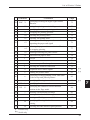
List of Control Codes
Character
Command
Specifying/Clearing 90 degree right rotated
Page
30
ESC V
31
W
Setting the printing area in thePage mode
72
32
\
Specifying the relative printing position
74
33
a
Arranging the printing position
75
34
c0
Selecting the printing sheet
75
35
c1
Selecting the setting sheet
76
36
c3
37
c4
38
c5
Enabling/Disabling the panel switch
77
39
d
Print and feed paper n lines
78
40
i
Full cut
78
41
m
Partial cut
78
42
p
Generates a specification pulse
78
43
t
Selecting the character code table
79
44
u
Peripheral device status signal
80
45
v
Sending the printer status
81
46
z
47
48
49
GS
GS
character
Selecting an effective paper end sensor for
outputting the paper end signal
Selecting the paper end sensor that is effevtive
for stopping printing
Specifying/Clearing printing of the same data
by the receipt and journal printers
72
76
77
82
{
Specifying/Clearing inverted characters
82
!
Specifying the character size
83
$
Specifying the character vertical absolute
position in the Page mode
*
Defining a downloaded bit image
85
51
/
Printing a downloaded bit image
86
52
:
Starting and Ending a macro definition
87
53
B
54
H
printing
Selecting the HRI character print position
**
84
50
Specifying/Clearing black/white reverse
**
**
88
88
*: Parallel only
**: Serial only
47
7
Chapter 7 Print Control Codes
Character
48
Page
55
L
Setting the left margin
89
56
M
Specifying/Clearing reduced character printing
90
57
P
Setting the basic calculation pitch
91
58
V
Cutting of paper
92
59
W
Setting the print area width
93
Specifying the relative position of characters in
60
\
61
^
62
a
63
f
Selecting the font of HRI characters
100
64
h
Selecting the bar code height
100
65
k
Printing bar codes
101
66
r
Sending of the status
103
67
w
Selecting the horizontal size of a bar code
105
*: Parallel only
**: Serial only
7
Command
the vertical direction in the page mode
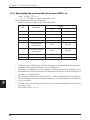
Execution of a macro
Enabling/Disabling automatic sending of
the status
95
96
97
**
**
Input Data Format
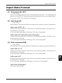
Input Data Format
(1) Horizontal tab (HT)
Code: [09] h
Moves the printing position to the next horizontal tab position. The horizontal tab
position is set by ESC D. Initial horizontal tab positions are set at every eighth character in Font A (9th, 17th, 25th and 33rd columns).
(2) Line feed (LF)
Code: [0A] h
Menu Setting: The operation differs according to the contents set by the CR operation.
In the case of CR + LF
If data exist in the print buffer, a line feed is executed after printing. If no data exist, a
line feed only is executed.
A LF code input immediately following a CR code is disregarded.
In the case of LF and in the case of Disregard
If data exist in the print buffer, a line feed is executed after printing. If no data exist, a
line feed only is executed.
A LF code input immediately following a CR code is disregarded.
(3) Print command (CR)
Code: [0D] h
Menu Setting: The operation differs according to the contents set by the CR operation.
In the case of + LF
If data exist in the print buffer, a line feed is executed after printing. If no data exist, a
line feed only is executed.
A CR code input immediately following a LF code is disregarded.
In the case of LF
If data exist in the print buffer, a line feed is executed after printing. If no data exist, a
line feed only is executed.
A CR code input immediately following a LF code is not disregarded.
In the Case of Disregard
This code is disregarded.
49
7
Chapter 7 Print Control Codes
(4) Printing in the page mode and return (FF)
Code: [0C] h
The data developed in the entire printing area are printed all at once and the printer
returns to the Standard mode.
• All the developed data are cleared after printing.
• The printing area set by ESC W is initialized.
• The paper cut is not executed.
• The head of the line is made the next printing position.
• This is valid only in the Page mode.
(5) Canceling of print data in the page mode
Code: [18] h
In the Page mode, this cancels all the data in the currently set printing area.
• Valid when Page mode is selected only.
• The portions of data included in the currently set printing area are canceled even if
they are data from a previously set printing area.
(6) Journal tab (RS)
Code: [1E] h
Moves the print position to the head of the journal paper.
[Note] Valid only when Receipt/Journal is selected, printing of the same data by the
receipt and journal printers is cleared and the print position is in the receipt area.
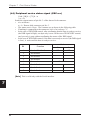
(7) Sending the status in real time [DLE EOT n)
Code: [10] h + [04] h + n
* (1 ≤ n ≤ 4) Data are expressed in Hex code.
The status is sent in real time according to the n specification.
• n is as follows.
n = 1: Sends the printer status.
n = 2: Sends the off-line factor status.
n = 3: Sends the error factor status.
n = 4: Sends the paper sensor status.
7
50
Input Data Format
•
•
•
•
•
•
•
Each status shows the current state. Also, each status is 1 byte of data.
The status is sent without confirming the receiving ready state of the host computer.
Executed in the off-line state, when the receiving buffer is full and in the error
state.
This command is processed during reception.
In cases where the [10] h [04] h n (1 ≤ n ≤ 4) data string is received, even when it
is other than this command, the user's attention is necessary because the printer's
operation will be the same as when this command is executed.
[Example]
In ESC* m nl nh [dl....dk], d1 = [10] h, d2 = [04] h, d3 = [01] h.
Do not insert this command in the code strings of other commands consisting of
codes with 2 bytes or more.
[Example]
If the host side wants to send ESC 3 n, then DLE EOT 3 is sent just at the point
where ESC 3 has been sent, the printer will process the command as ESC 3 [10] h.
Therefore, the user's attention is necessary.
In cases where ASB is valid due to GS a, it is necessary to distinguish between the
status by this command and the ASB status.
Distinguishing the Sending Status
Since the values of specific bits in the status sent by this printer, it is possible to
distinguish which command's status is received.
However, in the case where ASB is used, after confirming the first byte of ASB,
process the next 3 bytes, excluding the XOFF, as ASB data. If this is not done, it
will be impossible to distinguish between status messages such as ESC u and the
second and subsequent bytes of ASB.
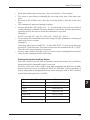
Command and Function
Status
GS I
<0**0****>B
GS r
<0**0****>B
XON
<00010001>B
XOFF
<00010011>B
DLE EOT
<0**1**10>B
ASB (1st byte)
<0**1**00>B
ASB (2nd through 4th byte)
<0**0****>B
7
51
Chapter 7 Print Control Codes
(1) Printer Status (when n=1 is specified)
Bit
Function
0
1
0
Not used
Fixed at 0
1
Not used
Fixed at 1
2
Status of drawer pint No. 3
3
On-line/Offline
4
Not used
5
Not defined
—
—
6
Not defined
—
—
7
Not used
“L”
“H”
On-line
Off-line
Fixed at 1
Fixed at 0
(2) Off-line Factor Status (when n = 2 is specified)
Bit
0
Not used
1
Not used
2
7
Function
Cover Open
3
Paper Feed by paper feed switch
4
Not used
5
Printing not stopped by No Paper
6
Error generated
7
Not used
Value
0
1
Fixed at 0
Fixed at 1
Cover
Cover
Closed
Closed
No paper
Paper feed
feed
in progress
Fixed at 1
No stopped
Stopped
None
Error exists
Fixed at 0
Bit 5: When the roll paper end sensor signals that there is no paper, or when there is
no paper when the roll paper near end sensor is enabled by ESC c 4, printing is stopped.
At this time, bit 5 = 1.
52
Input Data Format
(3) Error Factor Status (when n = 3 is specified)
Bit
Function
Value
0
1
0
Not used
Fixed at 0
1
Not used
Fixed at 1
2
Fixed at 1
—
—
3
Auto cutter error generated
4
Not used
5
Unrecoverable error
No error
6
Auto recovery error generated
No error
7
Not used
Error
No error
occurred
Fixed at 1
Error
occurred
Error
occurred
Fixed at 0
Bit 3: If this error is generated due to a paper jam, etc., you can recover by DLE ENQ
n (1 ≤ n ≤ 2) after the error cause is eliminated. If the error was generated due to a fault
in the circuit (broken connection, etc.), then you cannot recover.
Bit 6: If an abnormally high temperature is detected in the print head and during the
time that printing is stopped until the head temperature drops, bit 6 = 1.
(4) Continuous Paper Sensor Status (when n = 4 is specified)
Bit
Function
Value
0
1
0
Not used
Fixed at 0
1
Not used
Fixed at 1
2
Journal near end detection
3
Receipt near end detection
4
Not used
5
Journal end detection
6
Receipt end detection
7
Not used
Paper
7
No paper
present
Paper
No paper
present
Fixed at 1
Paper
No paper
present
Paper
No paper
present
Fixed at 0
53
Chapter 7 Print Control Codes
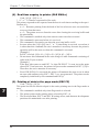
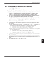
(8) Real time enquiry to printer (DLE ENQ n)
Code: [10] h + [05] h + n
* (1 ≤ n ≤ 2) Data are expressed in Hex code.
The printer responds to the requests from the host in real time according to the specification of n.
n = 1: Resumes printing from the head of the line where an error occurred after
recovery from that error.
n = 2: The printer recovers from the error after clearing the receiving buffer and
the print buffer.
• This command is enabled only when an auto cutter error has occurred.
• This command is processed when it is received.
• This command is executed even when the receiving buffer is full.
• In cases where the [10] h [05] h n (1 ≤ n ≤ 2) data string is received, even when it
is other than this command, the user's attention is necessary because the printer's
operation will be the same as when this command is executed.
[Example]
In ESC* m nl nh [d] k, d1 = [10] h, d2 = [05] h, d3 = [10] h.
• Do not insert this command in the code strings of other commands consisting of
codes with 2 bytes or more.
[Example]
If the host side wants to send ESC 3 n, then DLE EOT 3 is sent just at the point
where ESC 3 has been sent, the printer will process the command as ESC 3 [10] h.
Therefore, the user's attention is necessary.
• Even if DLE ENQ 2 is executed, the printer will maintain the state it was in when
an error with contents set by ESC !, ESC 3, etc. was generated. The printer can be
completely initialized by this command and ESC@.
(9) Printing of data in the page mode (ESC FF)
Code: [1B] h + [0C] h
This prints out all the data developed in the entire printing area in the Page mode at
once.
• This command is enabled only when Page mode is selected.
• The printer prints on the printing sheet selected by ESC c 0.
• The developed data, ESC T and ESC W setting values, and character development
positions are maintained even after printing.
7
54
Input Data Format
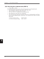
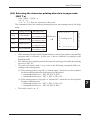
(10) Setting the space between characters (ESC SP n)
Code: (1B) h + [20] h + n
* (0 ≤ n ≤ 20) Data are expressed in Hex code.
The space to the right of characters is set in [n x basic calculated pitch] inches.
• When the horizontal magnification of characters is 2 or greater, the amount of
space on the right becomes larger at the same magnification.
(1) This does not effect Kanji.
• The amount of space on the right side of characters can be set independently in the
Standard mode and the Page mode.
• The basic calculated pitch is set by GS P. Also, after the amount of right space is
set, this amount of space does not change even if the basic calculated pitch is
changed by GS P.
• If there is a fraction, interpolation is carried out at the mechanism's minimum pitch.
Remainders are cut off.
• In the Standard mode, the basic calculation pitch (x) in the horizontal direction is
used.
• In the Page mode, the basic calculation pitch used according to the starting point is
as follows.
(1) If the starting point is specified as "top left" or "bottom right" by ESC T, the
horizontal basic calculation pitch (x) is used.
(2) If the starting point is specified as "top right" or "bottom left" by ESC T, the
vertical basic calculation pitch (y) is used.
• The maximum value that can be set for the amount of right space is 255/203 inch.
Settings which exceed this maximum value are rounded to the maximum value.
• The minimum value is “n = 0”.
7
55
Chapter 7 Print Control Codes
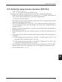
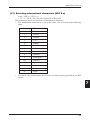
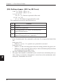
(11) Specifying the print mode all at once (ESC ! n)
Code: [1B] h + [21] h + n
* (0 ≤ n ≤ FF) Data are expressed in Hex code.
This command specifies the print mode.
• Each bit of n is as shown in the following table.
•
•
•
•
7
•
•
56
Bit
Function
0
Character Font
1
Not defined
2
Not defined
3
Value
0
1
Font A
Font B
Bold
Clear
Specify
4
Vertical double
enlargement
Clear
Specify
5
Horizontal double
enlargement
Clear
Specify
6
Not defined
7
Underline
Clear
Specify
If both vertical and horizontal double enlargement are specified at the same time,
quadruple enlargement characters can be configured.
Underlines are applied to all the characters printed, but portions skipped with a
horizontal tab (HT) and portions with characters which are rotated 90 degrees to
the right are not underlined.
The underline width is the width set in ESC _ with no relation to the character size.
Mixed printing with double enlarged characters, and with characters of different
sizes, is possible.
Character sizes can also be specified by GS !, but the command that is set last is the
one that is valid.
The initial value is “n = 0”.
Input Data Format
(12) Specifying the absolute print position (ESC $ n1 n2)
Code: [1B] h + [24] h + n1 + n2
* (0 ≤ n1 ≤ FF)
(0 ≤ n2 ≤ 3) Data are expressed in Hex code.
The next printing start position is specified as an absolute position with the left margin
position as the reference. The next printing start position is [(n1 +n2 x 256) x basic
calculation pitch] inch from the left margin position.
• A specification that exceeds the printing area is disregarded.
• The basic calculation pitch is set by GS P.
• If there is a fraction in the calculation results, it is interpolated at the mechanism's
minimum pitch. Remainders are cut off.
• The horizontal basic calculation pitch (x) is used in the Standard mode.
• The following operations are executed in the Page mode according to the starting
point.
(1) If the starting point is specified as "top left" or "bottom right" by ESC T, an
absolute position in a direction perpendicular to the paper feed direction (the
character's horizontal direction) is specified. The horizontal basic calculation
pitch (x) is used in calculations at this time.
(2) If the starting point is specified as "top right" or "bottom left" by ESC T, the
absolute position in the paper feed direction (the character's horizontal direction) is specified. The vertical basic calculation pitch (y) is used at this time.
(13) Specifying/Clearing the download character set (ESC % n)
Code: [1B] h + [25] h + n
* (0 ≤ n ≤ FF) Data are expressed in Hex code.
This command specifies and clears download characters.
• In n, the least significant bit (n0) becomes enabled. The meaning of the least
significant bit (n0) is as follows.
n0 = 0: The download character set is cleared.
n0 = 1: The download character set is specified.
• Download characters and a download bit image (GS *) cannot be defined at the
same time.
• The initial value is “n0 = 0”.
57
7
Chapter 7 Print Control Codes
(14) Defining download characters (ESC & s n m a (D1 D2~Dn))
Code: [1B] h + [26] h + s + n + m + a + Dn
* (s = 03)
(20 ≤ n ≤ 7E)
(20 ≤ m ≤ 7E)
(In the case of Font A, (0 ≤ a ≤ 0C)
(In the case of Font B, (0 ≤ a ≤ 09)
Data are expressed in Hex code.
This command defines download alphanumeric characters.
• s indicates the number of bytes in the vertical direction.
• n indicates the starting character code and m indicates the end character code. If
only one character is defined, n is made equal to m.
• Definable character codes are within the range (20) H ~ (7E) H of ASCII code. A
total of 95 characters can be defined.
• a indicates the number of horizontal dots that are defined.
• Dn are the defining data and indicate the pattern of “a” dots from the left end in the
horizontal direction. The pattern remaining on the right end is filled with spaces.
• Once it is defined, a download character remains valid until it is redefined, until
ESC @ is executed, until GS * is executed or until the power is switched OFF.
• It can be known whether characters are downloaded or not by executing ESC v.
(In the case of Serial only.)
7
58
Input Data Format
Example
• In the case of Font A
12 Dots
p1
p4
p7
p34
MSB
24 Dots
p2
p5
p35
LSB
p3
p6
p36
7
p1=<OF>H
p4=<30>H
p7=<40>H
...
p2=<03>H
p5=<80>H
p8=<40>H
...
p3=<00>H
p6=<C0>H
p9=<20>H
...
59
Chapter 7 Print Control Codes
•
In the case of Font B
9 Dots
d1 d4 d7
d25
MSB
24 Dots d2 d5
d26
d3 d6
d27
LSB
7
60
d1 = <03>H
d4 = <01>H
d7 = <02>H
...
d2 = <FF>H
d5 = <00>H
d8 = <00>H
...
d3 = <FF>H
d6 = <20>H
d9 = <10>H
...
Input Data Format
(15) Specifying a bit image (ESC * m n1 n2 D1~Dn)
Code: [1B] h + [2A] h + m + n1 + n2 + Dn
* (m = Bit Image Mode (See the following table.)
(0 ≤ n1 ≤ FF)
(0 ≤ n2 ≤ 03) Data are expressed in Hex code.
Data are printed in a bit image in accordance with the Bit Image mode specified by m.
• The number of dots printed in the horizontal direction is divided by 256, with n2
being the product and n1 the remainder.
• The total number of dots printed as the bit image is n1 + (256 x n2).
• If bit image data which exceed the space of one line are input, the portion of data
that runs over the end is dropped.
• Bit image data (Dn) are specified by “1” in printed bits and by "0" in nonprinted
bits.
• The Bit Image mode is as shown in the following table.
Vertical Direction
•
Horizontal Direction
m(Hex)
Mode
Number of
dots
Dot Density
Dot Density
0
8 dot single density
8
67 DPI
101 DPI
1
8 dot double density
8
67 DPI
203 DPI
20
24 dot single density
24
203 DPI
101 DPI
21
24 dot double density
24
203 DPI
203 DPI
If they deviate from the conditions of the values set in m (Bit Image mode), n1 and
subsequent data are processed as ordinary character data.
7
61
Chapter 7 Print Control Codes
Relationship between bit image data and printed dots
8-dot bit image
Bit Image Data
d1 d2 d3
MSB
d1
d2
d3
Bit Image Data
LSB
Printing Data
represent dots.
Printing Data
Single Density
24-dot bit image
Double Density
Bit Image Data
d1 d2 d3 d4 d5 d6 d7 d8 d9
d1
d4
d7
MSB
7
d2
d5
d8
d3
d6
d9
Bit Image Data
LSB
Printing Data
represent dots.
Printing Data
Single Density
62
Double Density
Input Data Format
(16) Specifying/Clearing underline (ESC – n)
Code: [1B] h + [2D] h + n
* (0 ≤ n ≤ 02, 30 ≤ n ≤ 32) Data are expressed in Hex code.
This command specifies or clears underlines.
• Underlines are applied to the full width of all the characters printed, but portions
skipped with a horizontal tab (HT) or by a relative/absolute print position specification (ESC (, ESC $), and characters which are rotated 90 degrees to the right, are
not underlined.
• During the printing of Kanji, this underline specification/clearing command cannot be applied.
• The type of underline is distinguished by the value of n, as follows.
n = 0, 30: Underline is cleared.
n = 1, 31: A one dot wide underline is specified.
n = 2, 32: A two dot wide underline is specified.
• The initial value is “n = 0”.
(17) Specifying the 1/6 inch line feed amount (ESC 2)
Code: [1B] h + [32] h
Sets the line feed amount at 1/6 inch per line.
• The line feed amount for a set sheet selected by ESC c1 is set by this command.
7
63
Chapter 7 Print Control Codes
(18) Specifying the line feed amount (ESC 3 n)
Code: [1B] h + [33] h + n
* (0 ≤ n ≤ FF) Data are expressed in Hex code.
This command sets the line feed amount per line in [n x basic calculation pitch] inches.
• Sets the line feed amount for a set sheet selected by ESC c1.
• The line feed amount can be set independently for the receipt and journal printers,
but if printing of the same data by both the receipt and journal printers is specified,
and printing is done in the Page mode, the line feed amount set for the journal
printer is disregarded and the amount set for the receipt printer is made valid.
• The line feed amount can be set independently in the Standard mode and the Page
mode.
• The basic calculation pitch is set by GS P. Also, once the line feed amount has
been set, it does not change even if the basic calculation pitch is changed by GS P.
• If there is a fraction as a result of calculations, interpolation is carried out at the
mechanism's minimum pitch. Remainders are cut off.
• In the Standard mode, the basic calculation pitch (y) for the vertical direction (paper feed direction) is used.
• If used in the Page mode, movement from the starting point is as follows.
(1) If the starting point is specified as “top left” or “bottom right” by ESC T, the
vertical basic calculation pitch (y) (the paper feed direction) is used.
(2) If the starting point is specified as “top right” or “bottom left” by ESC T, the
horizontal basic calculation pitch (x) (perpendicular to the paper feed direction) is used.
• The maximum line feed amount that can be set is 40 inches. Settings that exceed
the maximum value are rounded to the maximum value.
• The initial value is a line feed amount corresponding to 1/6 inch.
7
64
Input Data Format
(19) Controlling data input (ESC = n)
•
Code: [1B] h + [3D] h + n
* (0 ≤ n ≤ FF) Data are expressed in Hex code.
Each bit of n is as shown in the following table.
Value
•
•
•
Bit
Function
0
Printer
1
Not defined
2
Not defined
3
Not defined
4
Not defined
5
Not defined
6
Not defined
7
Not defined
0
1
Disable
Enable
If the printer is not selected, all the data received are destroyed until the printer is
selected by this command.
Even if the printer is not selected, the printer may, according to its operation, enter
the BUSY state.
The initial value is “n = 1”.
(20) Erasing download characters (ESC ? n)
Code: [1B] h + [3F] h + n
* (20 ≤ n ≤ 7E) Data are expressed in Hex code.
The download characters with the specified code are erased.
• n indicates the character code that erases the definition pattern. After erasure,
printing of the same patter as internal characters is done.
• The specified code definition patters of character fonts selected by ESC ! are erased.
• If the specified character code is not defined, this command is disregarded.
65
7
Chapter 7 Print Control Codes
(21) Printer initialization (ESC @)
Code: [1B] h + [40] h
Clears data stored in the internal print buffer and sets each setting in its initial state
(default state).
• Data in the internal input buffer are not cleared.
• Macro definition contents are not cleared.
(22) Setting the horizontal tab position (ESC D n NUL)
Code: [1B] h + [44] h + n + [00] h
* (1 ≤ n ≤ FF) Data are expressed in Hex code.
This command sets the horizontal tab position.
• n indicates the number of lines from the left margin to the horizontal tab position.
• The tab position is set at the character width x n position from the top of the line.
At this time, the character width includes the space to the right of the character and
when the horizontal enlargement rate is 2 or greater, the character width is also
made larger corresponding to the enlargement rate.
• The maximum number of places a tab position can be set is 32 positions. Settings
exceeding this number are disregarded.
• ESC D NUL clears all the set tab positions. After clearing, the horizontal tab (HT)
is disregarded.
• The initial value is every 8 characters for Font A and the amount of right space at
0 (9th column, 17th column...).
(23) Specifying/Clearing bold characters (ESC E n)
Code: [1B] h + [45] h + n
* (0 ≤ n ≤ FF) Data are expressed in Hex code.
This command specifies and clears bold characters.
• The least significant bit (n0) in n is valid.
• Control by the least significant bit (n0) is as follows.
n0 = 0: Clears bold printing.
n0 = 1: Specifies bold printing.
• This is valid for all characters.
• The dot configuration of bold characters is one dot each added to each character
horizontally.
7
66
Input Data Format
(24) Specifying/Clearing double strike characters (ESC G n)
Code: [1B] h + [47] h + n
* (0 ≤ n ≤ FF) Data are expressed in Hex code.
This command specifies and clears double strike characters.
• The least significant bit (n0) in n is valid.
• Control by the least significant bit (n0) is as follows.
n0 = 0: Clears double strike characters.
n0 = 1: Specifies double strike characters.
• In this printer, the effects of double strike printing are the same as those of bold
printing.
(25) Printing and paper feeding (ESC J n)
Code: [1B] h + [4A] h + n
* (0 ≤ n ≤ FF) Data are expressed in Hex code.
This command prints the data in the print buffer and feeds the paper [n x basic calculation pitch] inches.
• After execution, the top of the line becomes the next print position.
• This has no influence on the line feed amount set by ESC 2 or ESC 3.
• The basic calculation pitch is set by GS P.
• If there is a fraction as a result of calculations, interpolation is carried out at the
mechanism's minimum pitch. Remainders are cut off.
• In the Standard mode, the basic calculation pitch (y) for the vertical direction is
used.
• If used in the Page mode, movement from the starting point is as follows.
(1) If the starting point is specified as “top left” or “bottom right” by ESC T, the
printing position is moved in the paper feed direction (the vertical direction of
the characters). At this time, the vertical basic calculation pitch (y) is used.
(2) If the starting point is specified as “top right” or “bottom left” by ESC T, the
printing position is moved in the direction perpendicular to the paper feed
direction (the vertical direction of the characters). At this time, the horizontal
basic calculation pitch (x) is used.
• If [n x basic calculation pitch] exceeds 40 inches, the 40 inch portion of the paper
feed is executed.
67
7
Chapter 7 Print Control Codes
(26) Selecting the page mode (ESC L)
Code: [1B] h + [4C] h
This command switches the printer from the Standard mode to the Page mode.
• This command is valid when it is input at the top of a line.
• This command is invalid when input in the Page mode.
• The printer returns to the Standard mode after printing by FF is completed, or by
execution of ESC S.
• The character development position is the starting point specified by ESC T within
the printing area specified by ESC W.
• The values set in the following commands which are set independently in the Page
mode and the Standard mode, respectively, are switched to the values set in the
Page mode.
(1) Space amount setting
ESC SP, FS S
(2) Line feed amount setting ESC 2, ESC 3
• The following commands are valid only when set in the Page mode.
(1) ESC V
Specifying/Clearing 90 degree right rotated characters.
(2) ESC a
Arranging the position
(3) ESC {
Specifying/Clearing inverted characters.
(4) GS L
Setting the left margin.
(5) GS W
Setting the printing area
• The printer is returned to the Standard mode by ESC @.
7
68
Input Data Format
(27) Selecting international characters (ESC R n)
Code: [1B] h + [52] h + n
* (0 ≤ n ≤ 0D, n = 40) Data are expressed in Hex code.
This command carries out selection of international characters.
• The international character set is set by the value of n, as shown in the following
table.
n(Hex)
0
U. S. A.
1
French
2
German
3
U. K.
4
Danish
5
Swedish
6
Italian
7
Spanish
8
Japanese
9
•
Character Set
Norwegian
0A
Danish 2
0B
Spanish 2
0C
Latin America
0D
Korean
40
Legal
The initial value of n becomes the character set of the country specified by the DIP
switch.
7
69
Chapter 7 Print Control Codes
(28) Selecting the standard mode (ESC S)
Code: [1B] h + [53] h
This command switches the printer from the Page mode to the Standard mode.
• This command is valid only when input in the Page mode.
• Data developed in the Page mode are erased.
• The top of the line is made the next printing position.
• The printing area set by ESC W is initialized.
• The values set in the following commands which are set independently in the Page
mode and the Standard mode, respectively, are switched to the values set in the
Page mode.
(1) Space amount setting
ESC SP, FS S
(2) Line feed amount setting
ESC 2, ESC 3
7
70
Input Data Format
(29) Selecting the character printing direction in page mode
(ESC T n)
Code: [1B] h + [54] h + n
* (0 ≤ n ≤ 3)
(30 ≤ n ≤ 33) Data are expressed in Hex code.
This command selects the character printing direction and starting point in the Page
mode.
1,31
Bottom to Top
2,32
Right to Left
3,33
Top to Bottom
•
•
•
•
(B in diagram at right)
Bottom Right
(C in diagram at right)
Top Right
(Reference)
→
B →→→→
(A in diagram at right)
Bottom Left
A→→→→
Printing Area
C →→→→
0,30
← Paper Feed Direction
Printing Direction Starting Point
Top Left
Left to Right
D→→→→
n
(D in diagram at right)
If this command is input while Standard mode is selected, the printer's internal flag
operation only is executed. In this case, it has no influence on printing in the
Standard mode.
The character development position becomes the starting point within the printing
area set by ESC W.
The basic calculation pitch (x or y) used in the following commands differs according to the starting point.
(1) If the starting point is "top left" or "bottom right," (characters are developed in
the direction perpendicular to the paper feed direction)
• Commands which use x: ESC SP, ESC $, ESC \
• Commands which use y: ESC 3, ESC J, GS $, GS \
(2) If the starting point is "top right" or "bottom left," (characters are developed in
the paper feed direction)
• Commands which use x: ESC 3, ESC J, GS $, GS \
• Commands which use y: ESC SP, ESC $, ESC \
The initial value is “n = 0”.
71
7
Chapter 7 Print Control Codes
(30) Specifying/Clearing 90 degree right rotated characters
(ESC V n)
Code: [1B] h + [56] h + n
* (0 ≤ n ≤ 1, 30 ≤ n ≤ 31) Data are expressed in Hex code.
This command specifies or clears 90 degree right rotated characters.
• 90 degree right rotated characters cannot be underlined.
• The following is determined by the value of n.
n = 0, 30: 90 degree right rotated characters are cleared.
n = 1, 31: 90 degree right rotated characters are specified.
• If this command is input when Page mode is selected, the printer's internal flag
only operates and there is no influence on the Page mode.
• The initial value is “n = 0”.
(31) Setting the printing area in the page mode (ESC W)
Code: [1B] h + [57] h + x1 x2 y1 y2 dx1 dx2 dy1 dy2
* 0 ≤ x1 x2 y1 y2 dx1 dx2 dy1 dy2 ≤ FF
However, except when dx1 = dx2 = 0 or dy1 = dy2 = 0.
Sets the printing area position and size.
Horizontal Starting Point = [(x1 + x2 x 256) x basic calculation pitch] inches
Vertical Starting Point = [(y1 + y2 x 256) x basic calculation pitch] inches
Horizontal Length = [(dx1 + dx2 x 256) x basic calculation pitch] inches
Vertical Length = [(dy1 + dy2 x 256) x basic calculation pitch] inches
• If this command is input when the Standard mode is selected, the printer's internal
flag operations only are executed. In this case, Standard mode printing is not
influenced.
• If the horizontal starting point or the vertical starting point is outside the area where
printing is possible, command processing is terminated and the next data are processed as ordinary data.
• If the horizontal length or vertical length is 0, command processing is terminated
and the next data are processed as ordinary data.
• The character development position is the starting point in the printing area specified by ESC T.
• If (horizontal starting point + horizontal length) exceed the area that can be printed
in the horizontal direction, (the printable area in the horizontal direction - the horizontal starting point) is made the horizontal length.
• If (vertical starting point + vertical length) exceed the area that can be printed in
the vertical direction, (the printable area in the vertical direction - the vertical length)
is made the vertical length.
• The basic calculation pitch is set by GS P. Also, once the printing area has been
set, it will not change even if the basic calculation pitch is changed by GS P.
7
72
Input Data Format
•
•
•
If there is a fraction as a result of calculations, interpolation is carried out at the
mechanism's minimum pitch. Remainders are cut off.
The basic calculation pitch (x) is used in calculating the horizontal starting point
and the horizontal length and the basic calculation pitch (y) is used in calculating
the vertical starting point and the vertical length.
If X is the horizontal starting point, Y is the vertical starting point, Dx is the horizontal length and Dy is the vertical length, the printing area becomes as shown in
the following diagram.
→
Printing Area
→
Dy
Dx
(X+Dx–1, Y+Dy–1)
•
•
← Paper Feed Direction
Paper
(X, Y)
The area which this printer can print is a 432/203 inch in the horizontal direction
and 938/203 inch in the vertical direction.
The initial values are x1 = x2 = y1 = y2 = 0, dx1 = b0, dx2 = 01, dy1 = AA and
dy2= 03.
7
73
Chapter 7 Print Control Codes
(32) Specifying the relative printing position (ESC \ n1 n2)
Code: [1B] h + [5C] h + n1 + n2
* (0 ≤ n1 ≤ FF)
(0 ≤ n2 ≤ FF) Data are expressed in Hex code.
This command specifies the next printing start position with the current position as the
reference point. the next printing start position is a position [(n1 + n2 x 256) x basic
calculation pitch] inches from the current position.
• This command is disregarded if the specification exceeds the printing area.
• If a position is specified which is to the right of the current position with respect to
the character orientation, the value is a positive number (plus), and if a position is
specified which is to the left, the value is a negative number (minus).
• Negative numbers are expressed as a complement of 65536.
For example, if shifting by N pitch to the left, this is expressed by n1 + n2 x 256 =
65536 - N.
• The basic calculation pitch is set by GS P.
• If there is a fraction as a result of calculations, interpolation is carried out at the
mechanism's minimum pitch. Remainders are cut off.
• The horizontal basic calculation pitch (x) is used in the Standard mode.
• In the Page mode, operation is as follows according to the starting point.
(1) If the starting point is specified as “top left” or “bottom right” by ESC T, the
relative position in the direction perpendicular to paper feed (the characters'
horizontal direction) is specified. At this time, the horizontal basic calculation
pitch (x) is used.
(2) If the starting point is specified as “top right” or “bottom left” by ESC T, the
relative position in the paper feed direction (the characters' horizontal direction) is specified. At this time, the horizontal basic calculation pitch (y) is
used.
7
74
Input Data Format
(33) Arranging the printing position (ESC a n)
•
•
•
•
•
•
Code: [1B] h + [61] h + n
* (0 ≤ n ≤ 2, 30 ≤ n ≤ 32) Data are expressed in Hex code.
This command arranges all the print data on one line in specified positions.
Printing arrangement is executed as follows in accordance with the value of n.
n = 0, 30: Specifies left alignment.
n = 1, 31: Specifies centering.
n = 2, 32: Specifies right alignment.
This command is valid only if input at the head of a line.
If this command is input when selecting the Page mode, the printer's internal flag
only is operated.
This command does not influence the Page mode.
The initial value is “n = 0”.
(34) Selecting the printing sheet (ESC c 0 n)
Code: [1B] h + [63] h + [30] h + n
* (1 ≤ n ≤ 3) Data are expressed in Hex code.
Selects the sheet (receipt/journal) which is printed.
• Each bit of n is as shown in the following table.
Bit
•
•
•
•
Function
Value
0
1
0
Journal
Disable
Enable
1
Receipt
Disable
Enable
2
Not defined
3
Not defined
4
Not defined
5
Not defined
6
Not defined
7
Not defined
7
This command is valid if input at the head of a line.
If a Page mode printing sheet is selected, execute this command before ESC L.
Once the Page mode is selected, this command is disregarded.
If the value of n deviates from the definition range, this command is disregarded.
The initial value is “n = 3”.
75
Chapter 7 Print Control Codes
(35) Selecting the setting sheet (ESC c 1 n)
Code: [1B] h + [63] h + [31] h + n
* (1 ≤ n ≤ 3) Data are expressed in Hex code.
Selects the sheet which is the object of line feed settings set by ESC 2 and ESC 3.
• Each bit of n is as shown in the following table.
Bit
•
•
Value
Function
0
1
0
Journal
Disable
Enable
1
Receipt
Disable
Enable
2
Not defined
3
Not defined
4
Not defined
5
Not defined
6
Not defined
7
Not defined
If the value of n deviates from the definition range, this command is disregarded.
The initial value is “n = 3”.
(36) Selecting an effective paper end sensor for outputting the
paper end signal (ESC c 3 n)
Code: [1B] h + [63] h + [33] h + n
* (0 ≤ n ≤ FF) Data are expressed in Hex code.
Selects which state of which sensor for outputting to the Centronics parallel interface
PE signal.
7
Value
Bit
Function
0
1
0
Journal Near End Sensor
Disable
Enable
1
Receipt Near End Sensor
Disable
Enable
2
Journal End Sensor
Disable
Enable
3
Receipt End Sensor
Disable
Enable
4
Not defined
5
Not defined
6
Not defined
7
Not defined
• The initial value is “n = 3”.
[Note] This is valid for the parallel interface only.
76
Input Data Format
(37) Selecting the paper end sensor that is effective for
stopping printing (ESC c 4 n)
Code: [1B] h + [63] h + [34] h + n
* (0 ≤ n ≤ FF) Data are expressed in Hex code.
Selects which paper end sensor will stop printing.
•
•
•
•
•
Value
Bit
Function
0
Journal Near End Sensor
Disable
Enable
1
Receipt Near End Sensor
Disable
Enable
2
Not defined
3
Not defined
4
Not defined
5
Not defined
6
Not defined
7
Not defined
0
1
Even if the sensor which has been enabled senses the paper end, if printing of that
sheet is disabled, printing will not stop.
If multiple sensors have been specified as enabled, printing will stop when any one
of the sensors detects the paper end.
If printing is stopped, the print operation actually stops after the current line has
been printed and paper feed has been completed.
If paper end is detected by the journal or receipt sensor, the printer goes off-line
after printing stops.
The initial value is the state specified in the menu setting.
(38) Enabling/Disabling the panel switch (ESC c 5 n)
Code: [1B] h + [63] h + [35] h + n
* (0 ≤ n ≤ FF) Data are expressed in Hex code.
This command enables or disables the paper feed key (Receipt/Journal key).
• In n, the least significant bit (n0) becomes enabled.
• The least significant bit (n0) is as follows.
n0 = 0: Enables the paper feed key.
n0 = 1: Disables the paper feed key.
• The paper feed key is enabled regardless of this setting when the cover is open.
• The initial value is “n0 = 0”.
77
7
Chapter 7 Print Control Codes
(39) Print and feed paper n lines (ESC d n)
Code: [1B] h + [64] h + n
* (0 ≤ n ≤ FF) Data are expressed in Hex code.
This command prints the data in the print buffer and feeds the paper n lines.
• The set amount does not remain.
• The next printing start position is the head of the line.
• If the paper feed amount exceeds 40 inches, paper feeding of 40 inches only is
executed.
(40) Full cut (ESC l)
Code: [1B] h + [69] h
Executes a full cut of the receipt paper.
• This command is valid only if it is input at the head of a line.
(41) Partial cut (ESC m)
Code: [1B] h + [6D] h
Executes a partial cut (one point is left) of the receipt paper.
• This command is valid only if it is input at the head of a line.
(42) Generates a specification pulse (ESC p m n1 n2)
Code: [1B] h + [70] h + m + n1 + n2
* (0 ≤ n1 ≤ FF)
(0 ≤ n2 ≤ FF) Data are expressed in Hex code.
This command outputs the signals specified in n1 and n2 to connector pin m.
• The m bit (m0) is as follows.
m0 = 0: Drawer kick No. 2 pin
m0 = 1: Drawer kick No. 5 pin
• On time is n1 x 2 ms and Off time is n2 x 2 ms.
• If n2 is smaller than n1, Off time is made n1 x 2 ms.
7
78
Input Data Format
(43) Selecting the character code table (ESC t n)
Code: [1B] h + [74] h + n
* (0 ≤ n ≤ 6, n = FF) Data are expressed in Hex code.
Selects the page n of the character code table.
n
PC437 (USA)
1
Katakana
2
PC850 (Multilingual)
3
PC860 (Portuguese)
4
PC863 (Canadian-French)
5
PC865 (Nordic)
6
PC858 (Multilingual II )
FF
•
Character Type
0
Blank page
The initial value is “n = 0 or 2”. Depending on the setting of DIP switch.
See page 25
7
79
Chapter 7 Print Control Codes
(44) Peripheral sevice status signal (ESC u n)
Code: [1B] h + [75] h + n
* (n = 0)
Sends the current status of pin No. 3 of the drawer kick connector.
• n is as follows.
n = 0: Drawer kick connector pin No. 3.
• The status sent is 1 byte. The contents are as shown in the following table.
• If nothing is connected to the connector, bit 0 of n is always "1."
• In the case of DTR/DSR control, after confirming that the host is ready to receive
(the DSR signal is High), one byte only is sent. In the case of XON/XOFF control,
one byte only is sent without confirming the status of the DSR signal.
• In the case of DTR/DSR control, if the host is not ready to receive (the DSR signal
is Low), it waits until the host is ready to receive.
Value
Bit
Function
0
Level of Pin No. 3
1
Not defined
2
Not defined
3
Not defined
4
Not used
5
Not defined
6
Not defined
7
Not defined
[Note] This is valid only with the Serial interface.
7
80
0
1
“L”
“H”
Fixed at 0
Input Data Format
(45) Sending the printer status (ESC v)
Code: [1B] h + [76] h + n
This command sends the current printer status.
• The status sent is 1 byte. The contents are as shown in the following table.
• In the case of DTS/DSR control, after confirming that the host is ready to receive
(the DSR signal is High), one byte only is sent. In the case of XON/XOFF control,
one byte only is sent without confirming the status of the DSR signal.
• In the case of DTR/DSR control, if the host is not ready to receive (the DSR signal
is Low), it waits until the host is ready to receive.
Value
Bit
Function
0
1
0
Journal near end sensor
Paper present
No paper
1
Receipt near end sensor
Paper present
No paper
2
Journal near end sensor
Paper present
No paper
3
Receipt end sensor
Paper present
No paper
4
Not used
5
Downloading of character
No downloading
Downloading
6
Downloading of bit image
No downloading
Downloading
7
Not used
Fixed at 0
Fixed at 0
[Note] This is valid only with the Serial interface.
7
81
Chapter 7 Print Control Codes
(46) Specifying/Clearing printing of the same data by the receipt
and journal printers (ESC z n)
Code: [1B] h + [7A] h + n
* (0 ≤ n ≤ FF) Data are expressed in Hex code.
This command specifies and clears the printing of the same data by the receipt and
journal printers.
• In n, the least significant bit (n0) becomes enabled.
• The least significant bit (n0) is as follows.
n0 = 0: Printing of the same data is cleared.
n0 = 1: Printing of the same data is specified.
• This command is valid when it is input at the head of a line.
• Even if printing of the same data is specified, if both the receipt and journal printers are not selected as the printing sheet, the printing will not be the same for both
printers.
• When Page mode is selected, this command is disabled.
• The initial value is “n0 = 0”.
(47) Specifying/Clearing inverted characters (ESC { n)
Code: [1B] h + [7B] h + n
* (0 ≤ n ≤ FF) Data are expressed in Hex code.
In n, the least significant bit (n0) becomes enabled.
• The least significant bit (n0) is as follows.
n0 = 0: Inverted characters are cleared.
n0 = 1: Inverted characters are specified.
• This command is valid when it is input at the head of a line.
• If this command is input when Page mode is selected, the printer's internal flag
only operates, and there is no influence in the Page mode.
• The initial value is “n0 = 0”.
• The following shows a printing example.
7
If inverted characters are cleared:
If inverted characters are specified:
Japan CBM
Japan CBM
813 (3200) 6293
813 (3200) 6293
Paper Feed Direction
82
Input Data Format
(48) Specifying the character size (GS ! n)
Code: [1D] h + [21] h + n
* (0 ≤ n ≤ FF) Data are expressed in Hex code.
However, 1 ≤ Vertical Enlargement Rate ≤ 8,
1 ≤ Horizontal Enlargement Rate ≤ 8
This command specifies the character size (vertical enlargement rate/horizontal enlargement rate).
Bit
0
1
2
3
4
5
6
7
Function
Value Enlargement Rate
Vertical enlargement
rate specification
See the following Table 1.
Horizontal enlargement
See the following Table 2.
rate specification
Table 1 (Vertical Enlargement Rate)
3210 Bits
Value
Enlargement Rate
000B
00
Normal Size
0001B
01
2 times
0010B
02
3 times
0011B
03
4 times
0100B
04
5 times
0101B
05
6 times
0110B
06
7 times
0111B
07
8 times
7
Table 2 (Horizontal Enlargement Rate)
7654 Bits
Value
Enlargement Rate
000B
00
Normal Size
0001B
01
2 times
0010B
02
3 times
0011B
03
4 times
0100B
04
5 times
0101B
05
6 times
0110B
06
7 times
0111B
07
8 times
83
Chapter 7 Print Control Codes
•
•
•
•
•
•
•
Except for HRI characters, this command is valid for all characters.
If the setting of either the vertical enlargement rate or the horizontal enlargement
rate deviates from the definition range, this command is disregarded.
In the Standard mode, the vertical direction indicates the paper feed direction and
the horizontal direction indicates the direction perpendicular to the paper feed direction. Therefore, in specifying 90 degree rotated characters, the vertical-horizontal relationship with respect to the characters is reversed.
In the Page mode, the vertical direction indicates the vertical direction with respect
to the characters and the horizontal direction indicates the horizontal direction
with respect to the characters.
If characters with a different vertical enlargement rate are mixed on the same line,
they are arranged along the base line.
Horizontal and vertical double enlargement can also be specified and cleared by
ESC !, but the command that was processed last becomes the valid command.
The initial value is “n = 0”.
(49) Specifying the character vertical absolute position in the
page mode (GS $ n1 n2)
Code: [1D] h + [24] h + n1 + n2
* (0 ≤ n1 ≤ FF)
(0 ≤ n2 ≤ FF) Data are expressed in Hex code.
In the Page mode, this command specifies the position in the characters' vertical direction of the data development start position as an absolute position with the starting
point as the reference. The position in the characters' vertical direction of the next data
development start position is a position [(n1 + n2 x 256) x basic calculation pitch] inch
from the starting point.
• This command is disregarded when a mode other than the Page mode is selected.
• An absolute position specification which exceeds the specified print area is disregarded.
• The data development start position does not shift in the characters' horizontal
direction.
• The starting point used as the reference is specified by ESC T.
• Movements from the starting point specified by ESC T are as follows.
(1) If “top left” or “bottom right” is specified as the starting point, the absolute
position in the paper feed direction (characters' vertical direction) is specified.
At this time, the vertical basic calculation pitch (y) is used.
(2) If “top right” or “bottom left” is specified as the starting point, the absolute
position in the direction perpendicular to the paper feed direction (characters'
vertical direction) is specified. At this time, the horizontal basic calculation
pitch (x) is used.
• The basic calculation pitch is set by GS P.
• If there is a fraction, interpolation is carried out at the mechanism's minimum pitch.
Remainders are cut off.
7
84
Input Data Format
(50) Defining a downloaded bit image (GS * n1 n2 Dn)
Code: [1D] h + [2A] h + n1 + n2 + Dn
* (1 ≤ n1 ≤ FF)
(1 ≤ n2 ≤ 30)
(n1 x n2 ≤ 600) Data are expressed in Hex code.
This command defines a downloaded bit image with the number of dots specified in n1
and n2.
• The number of dots in the horizontal direction is n1 x 8 and the number of dots in
the vertical direction is n2 x 8.
• Dn is the bit image data.
• Once a downloaded bit image has been defined, it is valid until it is redefined, ESC
@ is executed, ESC & is executed or the power is switched OFF.
• Downloaded characters and a downloaded bit image cannot be defined at the same
time. If this command is executed, contents defining a downloaded character are
cleared.
• The relationship between bit image data and defined dots is shown in the following diagram.
n1x8 dots
d1
dn2+1
dn2x2+1
MSB
d2
dn2+2
dn2x2+2
LSB
n2x8 dots
7
dn2
dn1xn2x8
dn2x2
85
Chapter 7 Print Control Codes
(51) Printing a downloaded bit image (GS / m)
Code: [1D] h + [2F] h + m
* (0 ≤ m ≤ 3, 30 ≤ m ≤ 33) Data are expressed in Hex code.
This command prints a downloaded bit image in the mode specified by m.
• The modes selected by m are as shown in the following table.
m
Mode Name
0,30
Normal Mode
Horizontal
Double Mode
Vertical Double
Mode
Quadruple Mode
1,31
2,32
3,33
•
•
•
7
86
Vertical Dot Density Horizontal Dot Density
203 DPI
203 DPI
203 DPI
101 DPI
101 DPI
203 DPI
101 DPI
101 DPI
If data exist in the print buffer, this command is disregarded.
If a downloaded bit image is not defined, this command is disregarded.
The portion of a downloaded bit image that exceeds the length of a line is not
printed.
Input Data Format
(52) Starting and ending a macro definition (GS :)
Code: [1D] h + [3A] h
This command specifies starting and ending of a macro definition.
• Up to 2048 bytes can be used as contents in defining a macro. Any portion where
this 2048 bytes is exceeded is not defined.
• The definition contents are not cleared even when ESC @ (printer initiation) is
executed, so ESC @ can be included in the contents of a macro definition.
• Ordinary printing operations can be executed in the middle of macro definition.
• A “macro” is a string of commands corresponding to the user's purpose, taken
from the control commands of this printer, which are arranged to form a single
command in order to carry out daily operations efficiently. They can be used in
exactly the same way as existing commands can be used.
7
87
Chapter 7 Print Control Codes
(53) Specifying/Clearing Black/White reverse printing (GS B n)
Code: [1D] h + [42] h + n
* (0 ≤ n ≤ FF) Data are expressed in Hex code.
This command specifies or clears printing of black/white reversed characters.
• In n, the least significant bit (n0) becomes enabled.
The least significant bit (n0) is as follows.
n0 = 0: Clears printing of black/white reversed characters.
n0 = 1: Specifies printing of black/white reversed characters.
• Internal characters and downloaded characters can be printed as black/white reversed characters.
• The space to the right of characters, set by ESC SP, is also the object of black/
white reversed printing.
• Bit images, downloaded bit images, bar codes, HRI characters and portions skipped
due to HT, ESC $, ESC ( are not influenced.
• Spaces between lines are not influenced.
• Specification of black/white reversed printing has priority over underline specifications. Therefore, underlines are not added to black/white reversed characters,
even when underline is specified. However, the underline setting state does not
change.
• The initial value is “n0 = 0”.
(54) Selecting the HRI character print position (GS H n)
Code: [1D] h + [48] h + n
* (0 ≤ n ≤ 3, 30 ≤ n ≤ 33) Data are expressed in Hex code.
This command selects the HRI character print position when a bar code is printed.
• n has the meanings in the following table.
n (Hex)
7
•
•
88
Print Position
0,30
No printing
1,31
Above the bar code
2,32
Below the bar code
3,33
Both above and below the bar code
HRI characters are printed in the font selected by GS f.
The initial value is “n = 0”.
Input Data Format
(55) Setting the left margin (GS L n1 n2)
Code: [1D] h + [4C] h + n1 + n2
* (0 ≤ n1 ≤ FF)
(0 ≤ n2 ≤ FF) Data are expressed in Hex code.
This command sets the left margin specified by n1 and n2.
The left margin is [(n1 + n2 x 256) x basic calculation pitch] inch.
Printable Range
Left Margin
•
•
•
•
•
•
•
•
•
Width of Print Area
This command is valid only when input at the head of a line.
When Page mode is selected, if this command is input, the printer's internal flag
operation only is executed.
Setting of this command has no influence on the Page mode.
The maximum settable left margin is the same as the area in the horizontal direction that can be printed. Settings that exceed the maximum value are rounded to
the maximum value.
The basic calculation pitch is set by GS P. Also, once the left margin is set, it will
not change even if the basic calculation pitch is changed by GS P.
The horizontal basic calculation pitch (x) in GS P is used in calculating the left
margin. Also, if there is a fraction, interpolation is carried out at the mechanism's
minimum pitch. Remainders are cut off.
The left margin is set for the set sheet selected as valid by ESC c 1.
The left margin can be set independently for the receipt and journal printers, but if
printing of the same data in the receipt and journal printers is specified, the left
margin set in the journal printer is disregarded and that set in the receipt printer is
enabled.
The initial values are “n1 = 0” and “n2 = 2”.
89
7
Chapter 7 Print Control Codes
(56) Specifying/Clearing reduced character printing (GS M n)
Code: [1D] h + [4D] h + n
* (0 ≤ n ≤ FF) Data are expressed in Hex code.
However, bits 1, 2, 4, 5, and 6 should be 0.
This command specifies or clears printing of reduced characters.
Bit
0
•
•
•
•
•
7
•
•
•
•
90
Function
Reduced Character Printing in the
Vertical Direction
0
1
Clear
Specify
1
Not used
Fixed at 0
2
Not used
Fixed at 0
3
Not defined
4
Not used
Fixed at 0
5
Not used
Fixed at 0
6
Not used
Fixed at 0
7
Not defined
—
—
This command is valid for printing of all characters except HRI characters.
The reduction rate is 50%.
Specification and clearing of printing reduced characters has no influence on the
line feed amount.
If printing of reduced characters in the vertical direction is specified in the Standard mode, then reduced characters are printed in the paper feed direction. Therefore, 90 degree right rotated characters are reduced in the characters' horizontal
direction.
If printing of reduced characters in the vertical direction is specified in the Page
mode, then reduced characters are printed in the characters' vertical direction without relation to the printing direction selected by ESC T.
If characters of different vertical sizes are mixed on the same line, they are arranged along the printing base line.
If reduction printing is specified, underlines are not added, even when underlines
are specified. However, the underline specifications are not cleared. Also, if an
underline is specified or cleared in the middle of a reduced printing specification,
the printer's internal flag operation only is executed.
Characters with a high dot density may be difficult to read clearly.
The initial value is “n = 0”.
Input Data Format
(57) Setting the basic calculation pitch (GS P x y)
Code: [1D] h + [50] h + x + y
* (0 ≤ x ≤ FF)
(0 ≤ y ≤ FF) Data are expressed in Hex code.
This command sets the basic calculation pitch in the horizontal direction at (1/x) inch
and the basic calculation pitch in the vertical direction at (1/y) inch.
When x = 0, the horizontal basic calculation pitch returns to the initial value.
When y = 0, the vertical basic calculation pitch returns to the initial value.
• The vertical direction indicates the direction perpendicular to the paper feed direction, and the vertical direction indicates the paper feed direction.
• In the Standard mode, the parameters shown below are used without relationship
to the characters' direction (inverted, rotated 90 degrees to the right, etc.).
(1) Commands using x: ESC SP, ESC $, ESC \, FS S, GS L, GS W
(2) Commands using y: ESC 3, ESC J
• In the Page mode, the parameters shown below are used according to the characters' direction.
(1) If the starting point is “top left” or “bottom right” by ESC T, (characters are
developed in the direction perpendicular to the paper feed direction),
• Commands using x: ESC SP, ESC $, ESC W, ESC \, FS S
• Commands using y: ESC 3, ESC J, ESC W, GS $, GS \
(2) If the starting point is “bottom right” or “top left,” (characters are developed in
the paper feed direction)
• Commands using x: ESC 3, ESC J, ESC W, GS $, GS \
• Commands using y: ESC SP, ESC $, ESC W, ESC \, FS S
• Even when this command is executed, it has no influence on the various values
that are already set.
• If there is a fraction as a result of calculations combined with other commands,
interpolation is carried out at the mechanism's minimum pitch and remainders are
cut off.
• The initial values are “x = 203” and “y = 203”.
7
91
Chapter 7 Print Control Codes
(58) Cutting of paper (GS V m, GS V m n)
Code: (1) [1D] h + [56] h + m
(2) [1D] h + [56] h + m + n
* (1) (0 ≤ m ≤ 1)
(30 ≤ m ≤ 31) Data are expressed in Hex code.
(2) (41 ≤ m ≤ 42)
(0 ≤ n ≤ FF) Data are expressed in Hex code.
This command executes the specified paper cut.
m
Full Cut
1,31
Partial Cut (1 point left)
41
42
•
•
•
7
92
Function
0,30
(Cutting position + [n x basic calculation pitch] )
paper feed and full cut.
(Cutting position + [n x basic calculation pitch] )
paper feed and partial cut (1 point left).
In the Standard mode, this command is valid only if it is input at the head of the
line.
In the case of (1):
• When m = 1 or m = 31, a partial cut (1 point left) is executed.
In the case of (2):
• When n = 0, after executing paper feed to the cutting position, the paper is cut.
• When n ( 0, after executing paper feed [n x basic calculation pitch] inch from
the cutting position, the paper is cut.
The basic calculation pitch is set by GS P.
The paper feed amount is calculated by the vertical basic calculation pitch (y).
Also, if there is a fraction, interpolation is carried out at the mechanism's minimum pitch. Remainders are cut off.
Input Data Format
(59) Setting the print area width (GS W n1 n2)
Code: [1D] h + [57] h + n1 + n2
* (0 ≤ n1 ≤ FF)
(0 ≤ n2 ≤ FF) Data are expressed in Hex code.
This command sets the print area width specified by n1 and n2.
• The print area width is [(n1 + n2 x 256) x Basic calculation pitch] inch.
Printable Area
Left Margin
•
•
•
•
•
•
•
•
Print Area Width
This command is valid if it is input at the head of the line.
When the Page mode is selected, if this command is input, the printer's internal
flag operation only is executed.
Setting of this command has no influence on the Page mode.
The print area width is set for a setting sheet enabled by ESC c 1.
The print area width of the receipt and journal printers can be set independently,
but if printing of the same data in both the receipt and journal printers is specified,
the print area width set in the journal printer is disregarded and the setting of the
receipt printer is enabled.
If a value which exceeds the printable area of one line is input, it is set with the
entire area except the left margin used as the print area width.
The basic calculation pitch is set by GS P. Also, once the print area width has been
set, it will not change even if the basic calculation pitch is changed by GS P.
The horizontal basic calculation pitch (x) in GS P is used in calculating the print
area width. Also, if there is a fraction in the calculation results, interpolation is
carried out at the mechanism's minimum pitch. Remainders are cut off.
7
93
Chapter 7 Print Control Codes
•
When the first character at the head of a line is developed, if the print area width is
too small for the horizontal width of the character you are attempting to develop
(including the right space), the following processing is carried out for that line
only.
(1) The printer enlarges the print area to the right to a size where that character can
fit as long as it doesn't exceed the printable area.
Printable Area
Left Margin
Enlarged to the right
Print Area Width
(2) If a sufficient amount of space still cannot be secured by the processing in (1),
the print area is enlarged to the left (the left margin is reduced).
Printable Area
Left Margin
The left margin
is erased.
Enlarged to the right.
Print area width
•
7
•
94
(3) If a sufficient amount of space still cannot be secured by the processing in (2),
the right space is erased.
When developing a bit image (or a downloaded bit image), if the print area width
does not fill the bit image's minimum horizontal width (2 dots for single density, 1
dot for double density), the following processing is carried out for that line only.
(1) The print area is enlarged to the right until it is equal to the minimum horizontal width of the bit image, as long as it doesn't exceed the printable area.
(2) If a sufficient amount of space still cannot be secured by the processing in 1,
the print area is enlarged to the left (the left margin is reduced).
The initial value is “n1 = B0”, “n2 = 1”.
Input Data Format
(60) Specifying the relative position of characters in
the vertical direction in the page mode (GS \ n1 n2)
Code: [1D] h + [5C] h + n1 + n2
* (0 ≤ n1 ≤ FF)
(0 ≤ n2 ≤ FF) Data are expressed in Hex code.
This command specifies the position in the characters' vertical direction of the data
development start position as the relative position with the current position as the reference, in the Page mode. The next data development start position is the position
after shifting from the current position [(n1 + n2 x 256) x basic calculation pitch] inch.
• This command is disregarded except when the Page mode is selected.
• If the downward direction from the current position, with respect to the characters,
is specified, the value is a positive number (plus). If the upward direction is specified, the value is a negative number (minus).
• Negative numbers are expressed as a complement of 65,536.
For example, if moving in the upward direction by N pitch,
n1 + n2 x 256 = 65536 – N.
• A relative position which exceeds the specified print area is disregarded.
• Operation according to the starting point by ESC T is as follows.
(1) If the starting point is specified as “top left” or “bottom right”, the relative
position in the paper feed direction (vertical direction of the characters) is specified. At this time, the vertical basic calculation pitch (y) is used.
(2) If the starting point is specified as “top right” or “bottom left”, the relative
position in the direction perpendicular to the paper feed direction (vertical direction of the characters) is specified. At this time, the horizontal basic calculation pitch (x) is used.
• The basic calculation pitch is set by GS P.
• If there is a fraction, interpolation is carried out at the mechanism's minimum pitch.
Remainders are cut off.
7
95
Chapter 7 Print Control Codes
(61) Execution of a macro (GS ^ n1 n2 n3)
Code: [1D] h + [5E] h + n1 + n2 + n3
* (0 ≤ n1 ≤ FF)
(0 ≤ n2 ≤ FF)
(0 ≤ n3 ≤ 1) Data are expressed in Hex code.
This command executes the contents defined by a macro.
• The meanings of n1~n3 are as follows.
n1: Number of times the macro is executed.
n2: Wait time when a macro is executed.
The printer waits n2 x 100 msec each time a macro is executed.
n3: Macro execution mode
n3 = 0: Specifies continuous execution.
n3 = 1: Specifies execution when the paper feed key is pressed.
Continuous Execution: The macro is executed continuously the number of
times in n1, with the time interval specified in n2 inserted between executions.
Execution by pressing the paper feed key: After waiting the length of time
specified in n2, the ERROR indicator blinks and the printer waits for the paper
feed key to be pressed. When the key is pressed, the macro is executed one
time. This operation is repeated the number of times specified in n1.
• If this command is received during macro definition, it means that the macro definition is terminated. At this time, the contents of the definition are cleared.
• If the macro is not defined or if n1 = 0, nothing is executed.
• During execution of a macro in the case that n3 = 1, paper feed cannot be done
using the paper feed switch.
• During the time the printer is waiting for macro execution, the ERROR indicator
blinks.
7
96
Input Data Format
(62) Enabling/Disabling automatic sending of the status
(GS a n)
Code: [1D] h + [61] h + n
* (0 ≤ n ≤ FF) Data are expressed in Hex code.
This command selects the status that is the object of automatic status sending (ASB:
Automatic Status Back).
•
•
•
•
•
•
Value
Bit
Status that is Object of ASB
0
1
0
Status of drawer kick connector pin No. 3.
Disable
Enable
1
On-line
Disable
Enable
2
Error status
Disable
Enable
3
Paper sensor
Disable
Enable
4
Not defined
—
—
5
Not defined
—
—
6
Not defined
—
—
7
Not defined
—
—
If even one of the status items is enabled, the printer sends the status when this
command is executed. After that, each time a status that is enabled changes, that
status is sent. At that time, each status expresses the current status, so it is possible
that a status that is not enabled for ASB will change.
If every status is disabled, the auto status sending function (ASB function) is disabled.
If the ASB function in the initial state is enabled, the status at the point when
communications were first enabled after the power was switched on is sent.
The 4-byte status shown below is sent without confirm whether the host is ready to
receive or not. Except for the XOFF code, the 4-byte status is always continuous.
This command is executed when the receiving buffer is developed, so there is a
possibility of delay between the reception of the command and sending of the
status due to the status of the receiving buffer.
Even at times when the printer specification is disabled due to peripheral device
selection (ESC =), if the status changes, the 4-byte status is sent.
97
7
Chapter 7 Print Control Codes
•
If DLE EOT, GS I and GS r are used, it is necessary to distinguish between the
status from these commands and the ASB status. For the identification method,
see pages 49 ~ 51.
(1) First Byte (Printer Information)
Bit
Status
Value
0
1
0
Not used
0
—
1
Not used
0
—
2
Drawer kick connector pin No. 3 status
3
On-line/Off-line status
4
Not used
5
Cover status
6
7
Paper feed status from paper feed
switch
Not used
LOW
HIGH
On-line
Off-line
—
1
Closed
Open
Paper not
Paper
feeding
feeding
0
—
(2) Second Byte (Error Occurrence Information)
Bit
7
98
Status
Value
0
1
0
Not defined
—
—
1
Not defined
—
—
2
Not defined
—
—
3
Auto cutter error
No error
Error
4
Not used
0
—
5
Irrecoverable error
No error
Error
6
Auto recovery error
No error
Error
7
Not used
0
—
Input Data Format
(3) Third Byte (Paper Sensor Information)
Bit
Status
Value
0
1
0
Journal near end sensor status
Paper present
No paper
1
Receipt near end sensor status
Paper present
No paper
2
Journal end sensor status
Paper present
No paper
3
Receipt end sensor status
Paper present
No paper
4
Not used
0
—
5
Not defined
—
—
6
Not defined
—
—
7
Not used
0
—
(4) Fourth Byte (Paper Sensor Information)
Bit
•
Status
Value
0
1
0
Not defined
—
—
1
Not defined
—
—
2
Not defined
—
—
3
Not defined
—
—
4
Not used
0
—
5
Not defined
—
—
6
Not defined
—
—
7
Not used
0
—
The initial value is “n = 0” when menu setting error handshake is BUSY and “n =
2” when menu setting error handshake is disregarded.
99
7
Chapter 7 Print Control Codes
(63) Selecting the font of HRI characters (GS f n)
Code: [1D] h + [66] h + n
* (0 ≤ n ≤ 1, 30 ≤ n ≤ 31) Data are expressed in Hex code.
This command selects the font of HRI characters when printing a bar code.
• n has the following meanings.
n(Hex)
•
Font
0, 30
Font A
1, 31
Font B
The initial value is “n = 0”.
(64) Selecting the bar code height (GS h n)
Code: [1D] h + [68] h + n
* (1 ≤ n ≤ FF) Data are expressed in Hex code.
This command selects the bar code height.
• n indicates the number of dots in the vertical direction.
• The initial value is “n = A2”.
7
100
Input Data Format
(65) Printing bar codes. (GS kn 1 Dn NUL)
Code: [1D] h + [6B] h + n1 + Ds + [00] h ........1
0 ≤ n1 ≤ 6 Data are expressed in Hex code.
Code: [1D] h + [6B] h + n1 + s + Ds ........2
41 ≤ n1 ≤ 49
* Data are expressed in Hex code.
This command selects the bar code system and carries out printing.
• The head of the line is made the next printing start position.
• n is as follows.
In the case of (1)
m
Bar Code System
s Definition Range
D Definition Range
0
UPC-A
B≤s≤C
30 ≤ D ≤ 39
1
UPC-E
B≤s≤C
30 ≤ D ≤ 39
2
JAN13 (EAN)
C≤s≤C
30 ≤ D ≤ 39
3
JAN8 (EAN)
7≤s≤8
30 ≤ D ≤ 39
4
CODE39
1≤s
5
ITF
1≤s
6
CODABAR
1≤s
30 ≤ D ≤ 39, 41 ≤ D ≤ 5A,
20, 24, 25, 2B, 2D, 2E, 2F
(however, an
even number)
30 ≤ D ≤ 39
30 ≤ D ≤ 39, 41 ≤ D ≤ 5A,
24, 2B, 2D, 2E, 2F, 3A
In the case of (2)
m
Bar Code System
s Definition Range
41h
UPC-A
B≤s≤C
30 ≤ D ≤ 39
42h
UPC-E
B≤s≤C
30 ≤ D ≤ 39
43h
JAN13 (EAN)
C≤s≤C
30 ≤ D ≤ 39
44h
JAN8 (EAN)
7≤s≤8
30 ≤ D ≤ 39
45h
CODE39
1 ≤ s ≤ FF
46h
ITF
47h
CODABAR
1 ≤ s ≤ FF
48h
CODE93
1 ≤ s ≤ FF
0 ≤ s ≤ 7F
49h
CODE128
2 ≤ s ≤ FF
0 ≤ s ≤ 7F
1≤s
(Even Number)
D Definition Range
7
30 ≤ D ≤ 39, 41 ≤ D ≤ 5A,
20, 24, 25, 2B, 2D, 2E, 2F
30 ≤ D ≤ 39
30 ≤ D ≤ 39, 41 ≤ D ≤ 5A,
24, 2B, 2D, 2E, 2F, 3A
101
Chapter 7 Print Control Codes
7
In the case of (1):
• This command is ended by a NULL code.
• In the case of UPC-A and UPC-E, the bar code is printed at the point when 12
bytes of bar code data have been input, then data following next are processed as
ordinary data.
• In the case of JAN13, the bar code is printed at the point when 13 bytes of bar code
data have been input, then data following next are processed as ordinary data.
• In the case of JAN8, the bar code is printed at the point when 8 bytes of bar code
data have been input, then data following next are processed as ordinary data.
The number of data in an ITF bar code is always an even number. If the number of
data should happen to be odd, the final data are disregarded.
In the case of (2):
• s indicates the number of data. Then from the next data, n bytes are processed as
bar code data.
• If s deviates from the definition range, command processing is terminated and
processing of data from the next data is as for processing of ordinary data.
In the case of the Standard mode:
• If D deviates from the definition range, a paper feed only is executed and processing of data from the next data is as for processing of ordinary data.
• If the horizontal width of a bar code exceeds the one line printing range, the bar
code is not printed, but a paper feed only is executed.
• Paper feed by the amount of the bar code height (including HRI characters when
HRI characters are specified) is executed without relationship to the line feed amount
set by ESC 3, ESC 2, etc.
• This command is disregarded when data exist in the print buffer.
• When character code Dn is a character that cannot be printed, subsequent data are
treated as ordinary characters.
• After printing of a bar code is completed, the head of the line is made the next print
position.
• Except for inverted characters, the print mode (bold characters, double strike characters, underline, character size) has no influence.
In the case of Page Mode:
• Development of the bar code only is executed and printing is not done. When
development of the bar code is completed, the next dot after the last bar code data
is made the development start position for the next data.
• If D deviates from the definition range, command processing is terminated and
processing of the next data is the same as for ordinary data.
• At this time, the data development start position is not shifted.
• If the horizontal width of a bar code exceeds the print area, the bar code is not
printed and the data development start position is moved to the left edge of the
place where it deviated from the print area.
102
Input Data Format
(66) Sending of the status (GS r n)
Code: [1D] h + [72] h + n
* (1 ≤ n ≤ 2)
(31 ≤ n ≤ 32) Data are expressed in Hex code.
This commands sends the specified status.
n = 1, 31: Sends the paper sensor status.
n = 2, 32: Sends the drawer kick connector status.
• When the printer has Serial interface specifications:
In the case of DTR/DSR Control: After confirming that the host computer is ready
to receive, the status is sent. If it is impossible
for the host to receive, waiting continues until
it is possible for it to receive.
In the case of XON/OFF Control: The printer sends the status without confirming
if it is possible or impossible for the host computer to receive.
• This command is executed during development of the receiving buffer, so if a
command is received in accordance with the receiving buffer's state, there is a
possibility of a delay occurring while the status is being sent.
• If ASB is enabled by GS a, it is necessary to distinguish between the status from
this command and the status from ASB. See pages 50~53 for the identification
method.
• Paper Sensor Status (n = 1, 31 )
Bit
Printer Status
Value
0
1
0
Journal Near End Sensor Status
Paper present
No paper
1
Receipt Near End Sensor Status
Paper present
No paper
2
Journal End Sensor Status
Paper present
No paper
3
Receipt End Sensor Status
Paper present
No paper
4
Not used
0
—
5
Not defined
—
—
6
Not defined
—
—
7
Not used
0
—
7
Bits 2, 3: If there is no paper at the end sensors, this printer always goes off-line,
so this command is not executed. Therefore, a status of bit 2 = 1 or bit 3 = 1 will
not be sent.
103
Chapter 7 Print Control Codes
•
7
104
Drawer Kick Connector Status (n = 2, 32 )
Bit
Printer Status
0
1
Value
0
1
Status of Drawer Kick Connector Pin No. 3
“L”
“H”
Not defined
—
—
2
Not defined
—
—
3
Not defined
—
—
4
Not used
0
—
5
Not defined
—
—
6
Not defined
—
—
7
Not used
0
—
Input Data Format
(67) Selecting the horizontal size of a bar code (GS w n)
Code: [1D] h + [77] h + n
* (2 ≤ n ≤ 6) Data are expressed in Hex code.
Selects the horizontal size of a bar code.
• n indicates the number of dots of a fine bar in the horizontal direction.
• The initial value of the horizontal size is “n = 3”.
(68) Specifying and Clearing smoothing (GS b n)
Code: [1D] h + [62] h + n
Data are expressed in Hex code.
This command specifies or clears smoothing.
• In n, the least significant bit (n0) only is valid.
n0=0: Clears smoothing
n0=1: Specifies smoothing
• The object of smoothing is the internal characters and download characters.
• Even when smoothing is specified, if either the vertical enlargement rate or the
horizontal enlargement rate is normal even in only one direction, smoothing is not
executed.
• The initial value is “n0=0".
7
105
Chapter 7 Print Control Codes
7
106
Chapter 8
Character Code
Tables
8
Code Page
Japanese Code Table
International Character Code Table
107
Chapter 8 Character Code Tables
Code Page
8
108
Code Page
8
109
Chapter 8 Character Code Tables
8
110
Japanese Code Table
Japanese Code Table
8
111
Chapter 8 Character Code Tables
International Character Code Table
Note) n indicates the ESC R parameter.
8
112
Chapter 9
Appendices
Journal Protection Key
Maintenance, Cautions
Specifications
External View
9
113
Chapter 9 Appendix
Journal Protection Key
If a printer with optional specifications is used, the rear cover can be locked using the
journal protection key that is included.
Unlocked
Locked
9
114
Maintenance, Cautions
Maintenance, Cautions
Removing Paper Jams
[Caution] The print head and auto cutter become hot. Do not touch the print head cover or
the outside of the auto cutter with bare hands during printing or immediately after printing.
When removing jammed paper, first check to make sure the temperature of the print head
and auto cutter has dropped sufficiently.
1. Set the printer in the head up condition with the head
platen open.
2. Remove the jammed paper with utmost care.
If the jammed paper is wrapped around the platen roller, take it out a little at a time
while turning the paper feed knob.
•
•
When removing jammed paper, be sure to set the printer in the head up condition
with the head platen open.
Turning the paper feed knob while in the head down state, or attempting to pull the
paper out, could cause the printer to break down.
If the printer is covered with paper dust, remove it using a brush and vacuum
cleaner.
9
115
Chapter 9 Appendix
Cautions in Handling of Roll Paper
•
•
•
If chemicals or oil touch the paper, it could become discolored and the printed data
could fade away.
Do not scrape the paper with fingernails or with hard metal objects, etc. This could
cause the paper to become discolored.
Discoloration begins from a temperature of approximately 70°C. (158°F) Be careful
of the effects of heat, moisture and light, etc. on the roll paper.
Operating Temperature and Humidity
80%
5°C, 80% 30°C, 80%
Humidity 50%
40°C, 50%
30%
40°C, 30%
5°C, 30%
5°C
(41°F)
30°C 40°C
(86°F) (104°F)
Temperature
9
116
Specifications
Specifications
Model Classification
Different models are differentiated by the following model naming method.
CBM – 262 – R
J
100
Model Name
AC Power Supply
100:AC100V (50/60Hz)
120:AC120V (60Hz)
230:AC230V (50/60Hz)
Character Set
J: Japanese domestic
(supports Kanji codes)
F: foreign
Interface
R: Serial RS-232C
P: Compatible with Centronics
parallel
* Special AC adapter type and Power Cord
26AD-J (100 V 2-wire Cord)
26AD-U (120 V 3-wire Cord)
26AD-E (230 V round Pin Cord)
9
117
Chapter 9 Appendix
Basic Specifications
Item
Printing Method
Printing Width
Dot Density
Paper Feed Pitch
Printing Speed
Number of Printing
Columns
Types of Characters
Emulations
Bar Code Types
Line Interval
Paper
Interfaces
Input Buffer
Power Supply
Voltage
Power
Consumption
Weight
External
Dimensions
Operating
Temperature
and Humidity
Storage
Temperature
and Humidity
Reliability
9
118
Content
Line Thermal Printing Method
54mm, 432 dots
(Total dots in head: 448 dots)
8 dots/mm (Horizontal/Vertical)
0.125mm
62.5 mm/sec. (500 dot line/sec)
36 Columns (Horizontal 12 × Vertical 24 Font A)
48 Columns (Horizontal 9 × Vertical 24 Font B)
Alphanumeric, International Characters
ESC/POS™ compatible
UPC-A/E, JAN(EAN)13 Columns/8 Columns,
ITF CODE39, CODABAR
4.23 mm (1/6 inch)
Can be set by commands. Min. 1/203 inch.
Thermal roll paper 58 × φ 83 mm
φ 83 mm (See paper specifications.)
RS-232C/Centronics
72 Bytes/8K Bytes
(Set by the operation panel.)
AC120V±10%
60Hz
AC230V±10%
50/60Hz
42W
Approx. 2.3 kg
Remarks
Non-printing area:
2 mm on each end.
at maximum speed
Factory Option
Factory Option
ASCII Slide Pattern
Printing
Main unit only
128 × 359.5 × 162.5mm
5~40°C
30~80%RH(There should be no condensation.)
– 10~60°C 10~90%RH
Print head life:
Pulse resistance: 50 million pulses
(Page coverage: 12.5%)
Wear Resistance 30 Km
(Normal temperature and humidity,
using the recommended paper)
Printer Mechanism: MCBF 5 million lines
Auto Cutter Life: 300,000 cuts
see page 116
Specifications
Paper Specifications
(1) Specified Paper
Type: Thermal Recording Paper
Paper Width: 58 +0/-1 mm
Paper Thickness: 60~75 µ m
Roll Diameter: ø83 mm or less
Printing Surface: Outside of roll (front)
Specified Papers: Mitsubishi Paper Co. (Ltd.) F220VP
Shinoji Paper Co. (Ltd.) PD160R, PD160R-N
Nihon Paper Co. (Ltd.) TF 50KS-E2C
(2) Print Area
Paper Width 58 mm
2mm
Printing Area 54 mm
2mm
(3) Head and Cutter Positions
p Exit
o ß
Paper
Paper Feed
Direction
Approx.
æ41mm 41mm
b ^ [ ˚ u
CutterJ Position
9
Approx.
æ12mm 12mm
Head Position
w b h ˚ u
119
Chapter 9 Appendix
External View
162.
359.
12
9
120
Information Systems Division
CBM Bldg., 5-68-10, Nakano, Nakano-ku, Tokyo 164-0001, Japan
Head Office
Tel: (+81-3) 5345-7540 Fax: (+81-3) 5345-7541
PC74903-10
02 Printed in Japan