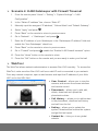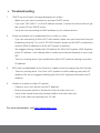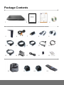
1
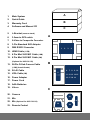
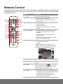
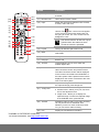
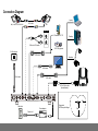
Package Contents Warranty card En glish War ra ntyPer iod of AVer Pr oductPurchased: AVer HVCSer ie s: 2YearsLimitedPartsandLabor. All AVerHVCSer ies Accessor ie s: 1Year PartsandLabor. 繁體中文 圓展科技股份有限公司保固說 明: AVer HVC產品系列:享2年保固期。 AVer HVC相關耗材:享1年保固期。 简体中文 圆展科技股份有限公司保修说明: AVer HVC产品系列:享2年保修期。 AVer HVC相关耗材:享1年保修期 。 日本語 アバーメディア製品保証期間 AVer HVCSer ie s 本体:2年間保証 AVer HVCSer ie s 付属品:1年間保証 2 ภ า ษ าไท ย ระ ยะเวลาการร ับประกันผลัตภัณฑัเอเวอ รัมัเ ดัย ชัดผลัตภัณฑัAVer HVCSer ie s: 2 ปัเ ฉพาะคัาอะไหลัแล ะคัาแรง อัปกรณัเส รัม AVer HVCSer ie s ทัังหมด: 1 ป ัคัาอะไหลัแล ะคัาแรง HVC-Series Video Conferencing System Deut sch Gar antiezeit für daser wor ben eAVer Pr odu kt: AVerHVCSere: i 2Jahre auf Teile undAr beit AlleAVer HVCSer ies -Zubehörteile: 1Jahr uaf Bauteile und Ver ar be itung. Quick Installation Guide Français Cond itionsdegar a ntiepour lespr odu itsdelagamme AVer: Gam m eAVerHVCSer ie s: 2anspièceset m ain s d’oeuvre. Touslesaccessoiresdelagam m e AVerHVCSer ie s: 1an, pièceset m aind’oeuvr e. Polski Gwar nacjanazakupionypr odukt AVer: AVer HVCSer ie s: 2latagwarncji a naczęści i robociznę PozostałeakcesoriaAVer HVC S er ie s: 1rokgwarncji a na części i r obociznę Português Per íod o deGar antiadoPr odutoAVer Adquir id os: Serei AVer HVC:2( dois) anos limitadoapeçasem ãod eobra TodososacessórosdaA i Ver HVCSer ie s: 1( um ) anolimitado apeçasemão- de-ra ob Pусс кий Ог раниченнаягаран тия Периодгарантиинаприообретенныйтоврар AVer 2годадляустройстваAVer HVCSer ie sсерия, зарядогоустр н айстваиподствки 1годд ляаккумулятораиаксессуаров Suomi AVer tuotteidentakuuaika: AVer HVCSer ies tuotteet: 2vuottaosille jatyölle. Kaikki AVer HVCSer ie slisätar vikkeet: 1vuosi osille jatyölle. Türkçe SatınalınanAVer ür ünü ngar a nti periodu: AVer HVCSer ie s: 2Senesınırlı parçaveişçilik BütünAVer HVC S er ie s Aksesuar lar i: 1yıllıkparçaveişçilik garantisi kapsam ında dır. Nederlands Gar antieper iod evanAVer pr odu ct naaankoop: AVer HVCSer ie s: 2jaar gar a ntieopar beidsloonen onder dele n. AlletoebehornvanA e Ver HVCSer ie s: 1jaar onder dele nen ar beidslo on. Italiano Per iod o di validitàdella gar anzi adel pr od ottoAVer acquistato: AVer HVCSer ie s: Gar anzi alimitataa2anni sui mater ialie sulla m anodope a.r Per tutti gli altri accessor i AVer HVCSer ie s: Gar anzi a limitataa1annosui mater ialiesulla m anodope a.r ﺓﻱﺏﺭﻉﻝﺍ ﺕﻥ ﻡﻝﻝﻥﺍﻡﺽﻝﺍﺓ ﺩﻡ ﻱ ﺩﻱﻡﺭﻑﺍ ﺓﺁﺭﺵﻥ ﻡ ﺓﻉﺍﺏﻡﻝﺍﺕﺍﺝ ﺍ: ﻱﺹﻝﺍﻭﺭﺍﻱﻍﻝﺍﻉﻁﻕﻝﻥﻱﻡﺍﻉ ﺓﺩﻡﻝ ﺩﻭ ﺩﺡﻡ ﻥﺍﻡﺽ ﺕﺱﺍﺏ ( ﺓﻥﺍ ءﺍﻥﺙ :AVer HVCSer ie sﺓﺱﻝﺱ )ﻁﻕﻑ ﺩﺡﺍﻭ ﻡﺍﻉﺓﻱﺭﺍﻁﺏﻝﺍ ﻱﺹﻝﺍﻭﺭﺍﻱﻍﻝﺍﻉﻁﻕﻝﻁﻕﻑ ﺩﺡﺍﻭ ﻡﺍﻉ ﺓﻥﺍ:AVer HVCSer ie sﺕﺍﻕﺡﻝ ﻡ ﻉﻱﻡﺝ Español PeríododeGar antíadePr odu ctosdeAVer de compr a: Distributor/Dealer AVer HVCSer ie s: Hasta2añosde garntíaenpiezasy a m an o deobr a . Todoslosaccesor ios deAVerHVCSer ies : 1añoen piezasym an o deobra. 1 2 3 Česky Záruční lhůtazakoupené oprod h uktuAVer: AVer HVCSer ie s: 2rokynadílyapráci Veškerépříslušenství AVer HVCSer ie s: 1roknadílyapráci. 4 PN: 303AALL- - ACR Madein Taiwan 5 6 7 8 9 10 11 12 13 14 15 16 17 18 19 20 21 22 23 1. Main System 2. Quick Guide 3. Warranty Card 4. Software and Manual CD 5. L-Bracket (camera stand) 6. 3.5mm to RCA cable 7. S-Video to Composite Converter 8. 3-Pin Standard XLR Adapter 9. DB9 RS232 Converter A B C A 1 2 3 4 10. HDMI Cable (1.5M) 11. 6 Pin Mini XLR MIC Cable (10M) 12. 6 Pin Mini XLR MIC Cable (5M) (Optional for HVC130/110) 13. 26-Pin D-Sub Camera Cable B (1.5M) (female/female) 14. RJ-45 Cable 6 7 8 9 10 5 15. VGA Cable (5M) 16. Power Adapter 11 12 13 14 15 16 17 18 19 17. Power Cord 18. AAA Batteries 19. Velcro C 20. Camera 21 21. Mic 23 22. Mic (Optional for HVC130/110) 23. Remote Control 20 22 Remote Control The remote control requires two (2) “AAA” size batteries (supplied), make sure batteries are installed properly before using. Aim the remote control to the HVC camera infrared sensor to operate the unit. Name Function (22) (23) (1 ) (2) (3) (21) (20) (19) (18) (17) (1) Call Start a call or add another party. (2) Phone Book Search contact to make a call. Make a selection in OSD menus or onscreen keyboard. Accept incoming call. Use these buttons to navigate through the selections in OSD menus or on-screen keyboard. Pan the zoomed in camera image or the captured image. Move around within the zoomed in camera image or the captured image. (3) Enter (16) (4) (4) (5) (6 ) (7) (8) (9) ▲,▼,◄, & ► (15) (14) (13) (12) (11) (5) Present (10) Enter to add, edit, delete or create group contact entry. Display the site name and icon during the meeting. Share either the video/image from the VGA IN port or the captured image. This present icon will appear on the screen to indicate sharing the present image. The present icon will disappear in 5 sec. (6) Vol +/- Increase/decrease the speaker volume. (7) Zoom +/- Zoom in/out the camera image or the captured image. (8) Mute Turn on/off the MIC. This mute icon will appear when the mic is turned off. The mute icon will become translucent in 5 sec. (9) Preset Press hold for 3 sec to set the position of the camera preset point from the selected number. The preset point can be set from 0-9. Press to move the camera target to the selected preset point number. (22) (23) (1 ) (2) (3) (21) (20) (19) (18) (17) Name Function (10) Backspace Move back one space and delete one character at a time. (11) Numeric Pad Use to enter numeric number. (12) Input Switch the input source between HVC camera, S-Video, Video and VGA. (13) Far/Near Select to control either near site or far site (16) camera. The cam. control icon will appear on the screen to show which camera site you are going to control. The cam. control icon will disappear in 5 sec. (4) (5) (6 ) (7) (8) (9) (15) (14) The camera from the far site can only be operated when the enable far site to control the camera is permitted. (13) (12) (11) (10) (14) Layout Change to different split screen mode. (15) Back Return to previous OSD menu selection or exit OSD mode. (16) Home Call up the main screen. (17) Hang Up End the call. (18) 16:9/4:3 Toggle between 16:9 or 4:3 to match the monitor aspect ratio. (19) Dual Switch to Dual monitor mode. This split the video conference screen and present screen. The video conference screen will be displayed on the monitor connected to the HDMI OUT of the main system and the present screen will be displayed on the monitor connected to the VGA OUT of the main system. (20) *Snapshot Capture the image from the camera. To view the captured image, press Image Ctrl. (21) *Image Ctrl Switch between camera and image mode. Camera mode - allows you to pan, tilt, zoom in/out, and adjust the focus. Image mode - allows you to display the captured image. To save the captured image in the USB flash drive, press Record. (22) *Record Start/Stop video recording. The video recording can only be saved in a USB flash drive. Whether you are in a video conference call or not, you can do the video recording. (23) Info Display the call statistics information. * Available in HVC330/310 model only. For more information, visit http://www.aver.com Connection Diagram MIC IN UT MICO Laptop MIC OUT MICIN Mic (2 nd Mic for HVC330/310) MIC cable MIC LCD TV LCD monitor/LCD TV AUDIO IN L 2 Phone to RCA cable Desktop AUDIO IN R LCD / DLP projector RJ-45 wall jack VGA cable Visualizer HDMI cable RJ-45 cable HDMI monitor VGA cable 26 Pin D-Sub cable (female/female) AUX MIC IN OUT MIC IN VGA IN VIDEO IN CAMERA IN DC 19V MIC Wall outlet Power adapter Power cord Suggested MIC Reception Range AVer 3m 3m Network Quick Setup Guide Note: Please pass this page to your Network Admin/IT Dept. For more detailed instructions in setting up Admin Password/System Name and Phonebook, please refer to the user manual CD or download the file from our website. Bandwidth Requirements From the remote press “Home” -> “Setting” -> “System Settings” -> “Network” Resolution Quality / Bandwidth MCU w/ 3 site* 4SIF (704x480)/4CIF (704x576) 256kbps/384kbps 768kbps/1152kbps 720p @ 30 frames per second (1280x720) 1Mbps (Point to Point only) (Example: If you plan to reserve 512k and not exceed 1Mbps for video conferencing then leave above settings as default. For a specific entry in the phonebook with which you wish to implement HD, you can set call quality to 1Mbps in the phonebook or while dialing.) AVer HVC H.323 Related Port Usage for Firewall Setup Port Function Type 1719 Gatekeeper UDP (Bi-Directional) 1720 H.323 Call setup TCP (Bi-Directional) 30000-30039 Signaling and control for audio, call, video, and data/FECC TCP and UDP 80 HTTP Interface (Web Tool) 5060 SIP TCP and UDP Enable H.323 ALG (if applicable) Four Possible Setup Scenarios for Video Conferencing (Please pick the scenario most suitable for your network environment) 1. Public IP Configuration (Outside of Firewall) - Do you have a dedicated public IP address for the AVer HVC System? 2. Private IP Configuration (Behind Firewall with Port Forwarding) 3. Behind Firewall with H.323 ALG Setup 4. Existing H.460 Gatekeeper/SBC (Session Border Controller) in your network Scenario 1: Public IP Configuration (Outside of Firewall) 1. From the remote press “Home” -> “Setting” -> “System Settings” -> “LAN Configuration”. 2. In the “Obtain IP address” line, choose “Static IP”. 3. Manually input the “Public IP address”, “Subnet Mask” and “Default Gateway”. 4. Select “Apply” and press 5. Press “Home” on the remote to return to the home menu. 6. Press the “Call” button on the remote and you are ready to make your first call. . Scenarios 2 and 3: Private IP Configuration (Behind Firewall with Port Forwarding) 1. From the remote press “Home” > “Setting” > “System Settings” > “LAN Configuration”. 2. In the “Obtain IP address” line, choose “Static IP”. 3. Manually input the assigned “Private IP address”, “Subnet Mask” and “Default Gateway”. 4. Select “Apply” and press 5. Press “Back” on the remote to return to previous menu. If you have H.323 ALG . enabled, skip to step 8. 6. Go to “Network” > “Firewall” and press 7. Enable the NAT check box and enter the Public IP in the “NAT Public (WAN) . Address” field. 8. Press the “Home” button on the remote to return to the home menu. 9. Press the “Call” button on the remote and you are ready to make your first call Scenario 4: H.460 Gatekeeper with Firewall Traversal 1. From the remote press “Home” > “Setting” > “System Settings” > “LAN Configuration”. 2. In the “Obtain IP address” line, choose “Static IP”. 3. Manually input the assigned “IP address”, “Subnet Mask” and “Default Gateway”. 4. Select “Apply” and press 5. Press “Back” on the remote to return to previous menu. 6. Go to “Network” - > “Gatekeeper” and press 7. Enter the IP address of your Gatekeeper in the “Gatekeeper IP address” field and . . enable the “Use Gatekeeper” check box. 8. Press “Back” on the remote to return to previous menu. 9. Go to “Firewall” and press ; enable the “Enable H.460 firewall traversal” option 10. Press the “Home” button on the remote to return 11. Press the “Call” button on the remote and you are ready to make your first call WebTool The WebTool allows network administrators to access AVer HVC remotely. To access the WebTool, make sure the AVer HVC unit has a valid IP and is connected to your network. From any network computer, open a web browser and input the IP address of your AVer HVC unit in the URL field. Cam. Control – allows you to view the camera, and access the screen interface and remote control. Phonebook – allows you to add, edit, delete, download and upload the phonebook entries. Call History – allows you to add contact in the phonebook, download call history and call from the list. Setting – allows you to update the system, download and restore the system, and get the test report. Contact Us – links you to our global website. Troubleshooting 1. “DHCP service Failed” message displayed on screen - Make sure you have connected to a proper DHCP server. - If you see “192.168.0.1” on the IP address column, it means the device did not get the correct IP from DHCP server. - Verify the security setting for MAC address in your network device. 2. Video conference call is established but no video or voice - If you are connecting to AVer HVC with firewall, make sure you have done the port forwarding correctly. For non H.323 ALG firewall, please set the NAT configuration and the WAN IP address on AVer HVC system is entered. - We suggest having a fixed public IP address for AVer HVC system. With Dynamic public IP address, it will change after a certain period which depends on your local ISP. - There’s a routing issue if you installed two AVer HVC systems sharing one public IP address. 3. MCU call is established but the 3rd site is unable to see the image from the 2nd site. - There’s a routing issue. Two AVer HVC systems could be sharing one public IP address. We do not suggest installing two AVer HVC systems and share one IP address. 4. Unable to connect to other VC system - Check to see if you dial the correct IP address. - Ensure the power status of the device from the other site is on. - Verify if the firewall blocks the inbound traffics from the other site. - Verify if the other site rejected your VC call. For more information, visit http://www.aver.com