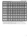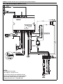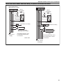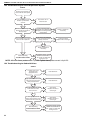
1
FOR YOUR SAFETY If you smell gas: 1. Open windows. 2. DO NOT try to light any appliance. 3. DO NOT use electrical switches. 4. DO NOT use any telephone in your building. 5. Leave the building. 6. Immediately call your local gas supplier after leaving the building. Follow the gas suppliers instructions. 7. If you cannot reach your gas supplier, call the Fire Department. WARNING Combat ® Tubular Unit Heaters Installation, Commissioning, Operation & Service Manual Model CTU 22 to 115 Fire Hazard Do not store or use petrol or other flammable vapours and liquids in the vicinity of this or any other appliance. Some objects will catch fire or explode when placed close to heater. Failure to follow these instructions can result in death, injury or property damage. WARNING Improper installation, adjustment, alteration, service or maintenance can result in death, injury or property damage. Read the installation, operation and service manual thoroughly before installing or servicing this equipment. Installation must be done by a registered installer/ contractor qualified in the installation and service of gas-fired heating equipment or your gas supplier. Quality in Any Language™ © 2008 Roberts-Gordon LLC Installer Please take the time to read and understand these instructions prior to any installation. Installer must give a copy of this manual to the owner. Owner Keep this manual in a safe place in order to provide your serviceman with necessary information. Roberts-Gordon Europe Limited Unit A, Kings Hill Business Park Darlaston Road, Wednesbury West Midlands WS10 7SH UK Telephone: +44(0)121 506 7700 Fax: +44 (0)121 506 7701 Service Telephone: +44 (0)121 506 7709 Service Fax: +44 (0)121 506 7702 E-mail: [email protected] E-mail: [email protected] www.rg-inc.com P/N X407UK Rev H 07/08 TABLE OF CONTENTS SECTION 1: Heater Safety...................................................... 2 SECTION 2: Installer Responsibility ..................................... 2 2.1 Clearances to Combustibles ........................................ 2 2.2 Corrosive Chemicals.................................................... 2 2.3 National Standards and Applicable Codes .................. 2 SECTION 3: Critical Considerations ..................................... 3 3.1 Basic Information ......................................................... 3 3.2 Location and Suspension ............................................ 3 3.3 Minimum Required Installation Clearances ................. 3 3.4 Clearances to Combustibles ........................................ 3 3.5 Ventilation .................................................................... 3 3.6 Gas Supply .................................................................. 3 3.7 Electrical Supply .......................................................... 3 3.8 Flue.............................................................................. 3 SECTION 4: Specifications .................................................... 5 4.1 CTUA .......................................................................... 5 4.2 CTUB, CTUC and CTUD ............................................. 6 4.3 General Technical Data Table ..................................... 7 4.4 Technical Data Table.................................................... 8 SECTION 5: Heater Installation.............................................. 9 5.1 General ........................................................................ 9 5.2 Handling ...................................................................... 9 5.3 Shelf Mounting and Suspension .................................. 9 SECTION 6: Flue Installation ............................................... 10 6.1 Flue Installation.......................................................... 10 6.2 Type C12, C32 & C62 Appliance .................................... 10 6.3 Type B22 Appliance..................................................... 10 SECTION 7: Air Supply......................................................... 12 7.1 Room Sealed Installation ........................................... 12 7.2 Open Flued Installation .............................................. 12 7.3 Building Ventilation ..................................................... 12 7.4 Isolated Equipment Rooms ........................................ 12 SECTION 8: Optional Heater Configurations...................... 13 8.1 Distribution Duct Work for CTUB, CTUC and CTUD Heaters .................................................... 13 SECTION 9: Gas Piping ........................................................ 14 9.1 Connections............................................................... 14 SECTION 10: Wiring and Electrical Information................. 15 10.1 Electrical Supply ...................................................... 15 10.2 Remote Controls ...................................................... 15 10.3 CTUA Wiring Diagram (Models 22-60) .................... 16 10.4 CTUA Wiring Diagram (Models 75-115)................... 17 10.5 CTUB/C Wiring Diagram (Models 22-40)................. 18 10.6 CTUB/C Wiring Diagram (Models 50-60)................. 19 10.7 CTUB/C Wiring Diagram (Models 75-115) ............... 20 10.8 CTUD Wiring Diagram (Models 22-60) .................... 21 10.9 CTUD Wiring Diagram (Models 75-115)................... 22 10.10 CTUD External Motor Alternative Wiring & Optional Thermostat/Time Switch ....................... 23 SECTION 11: Commissioning .............................................. 24 11.1 Pre-Commission Checks .......................................... 24 11.2 Gas Supply ............................................................... 24 11.3 Mechanical Checks................................................... 24 11.4 Begin Commissioning ............................................... 24 11.5 Combustion Testing .................................................. 26 11.6 Turning Off the Heater .............................................. 26 11.7 External Controls ...................................................... 27 11.8 Complete the Commissioning................................... 27 11.9 Instruction to the User .............................................. 27 SECTION 12: User Instructions............................................28 12.1 User Instructions ......................................................28 12.2 Heater Operation......................................................28 12.3 Common User Controls............................................28 12.4 Lighting Instructions .................................................28 12.5 Simple Fault Finding.................................................29 SECTION 13: Servicing.........................................................30 13.1 Servicing Instructions...............................................30 13.2 Burner Maintenance.................................................30 13.3 Fan/Motor Assembly Maintenance ...........................30 13.4 Heat Exchanger Maintenance ..................................30 13.5 Gas Control Valve Maintenance ...............................30 13.6 Flue Fan ...................................................................30 SECTION 14: Conversion Between Gases ..........................31 14.1 General ....................................................................31 14.2 Burner Conversion ...................................................31 14.3 Gas Valves ...............................................................31 SECTION 15: Troubleshooting .............................................32 15.1 General ....................................................................32 15.2 Troubleshooting For Automatic Ignition Burner Systems .......................................................33 15.3 Troubleshooting for Flame Supervision System .......34 15.4 Troubleshooting for Solenoid Valves ........................34 SECTION 16: Removal and Replacement Parts..................35 16.1 Gas Valve .................................................................35 16.2 Burner Compartment ...............................................36 16.3 Ignition Electrode and Flame Probe .........................37 16.4 Flue Fan ...................................................................38 16.5 Pressure Switch........................................................39 16.6 Ignition Control .........................................................40 16.7 CTUA Axial Fan/Guard/Motor Assembly ..................40 16.8 CTUB & CTUC Centrifugal Fan/Guard/Motor Assembly .................................................................40 16.9 Fan Data...................................................................41 © 2008 Roberts-Gordon LLC All rights reserved. No part of this work covered by the copyrights herein may be reproduced or copied in any form or by any means - graphic, electronic, or mechanical, including photocopying, recording, taping or information storage and retrieval systems - without the written permission of Roberts-Gordon LLC. Printed in U.K. TABLE OF FIGURES Figure 1: Installation Clearances and Clearances to Combustibles............................................................. 4 Figure 2: Suspension Methods ................................................. 9 Figure 3: Flue and Roof Detail ................................................ 10 Figure 4: Air Intake Terminal Cover......................................... 10 Figure 5: Vertical and Horizontal Flue Termination Type B22 Appliance ................................................... 11 Figure 6: Vertical and Horizontal Flue Termination Type C12 C32 & C62 Appliances ................................. 11 Figure 7: Heaters Installed in Isolated Equipment Rooms ...... 12 Figure 8: Ducting..................................................................... 13 Figure 9: Gas Connection with Stainless Steel Flex Connector ........................................................ 14 Figure 10: Automatic Burner Control Box Sequence............... 25 Figure 11: Gas Valve for Heater (Models 22 - 60) ................... 25 Figure 12: Gas Valve for Heater (Models 75 - 115) ................. 26 Figure 13: Heater Operating Sequence .................................. 28 Figure 14: Centrifugal Fan Orientation .................................... 41 Product Approval ROBERTS GORDON® appliances have been tested and CE certified as complying with the essential requirements of the Gas Appliance Directive, the Low Voltage Directive, the Electromagnetic Compatibility Directive and the Machinery Directive for use on natural gas and LPG when installed, commissioned and maintained in accordance with these instructions. These instructions refer to appliances designed to operate in the European Union. Appliances designed for other countries (Non-European Union) are available on request. This appliance must be installed in accordance with the local and national codes in force and used only in a sufficiently ventilated space, as specified in these instructions. Before installation, check that the local gas distribution systems, nature of gas and pressure, and adjustment of the appliance are compatible. 1 COMBAT® CTU UNIT HEATERS INSTALLATION OPERATION AND SERVICE MANUAL SECTION 1: HEATER SAFETY Your Safety is Important to Us! This symbol is used throughout the manual to notify you of possible fire, electrical or burn hazards. Please pay special attention when reading and following the warnings in these sections. Installation, service and annual inspection of heater must be done by a registered installer/contractor qualified in the installation and service of gas-fired heating equipment. Read this manual carefully before installation, operation, or service of this equipment. This heater is designed for heating non-residential indoor spaces. Do not install in residential spaces. These instructions, the layout drawing, local codes and ordinances, and applicable standards that apply to gas piping, electrical wiring, venting, etc. must be thoroughly understood before proceeding with the installation. SECTION 2: INSTALLER RESPONSIBILITY • To install the heater, as well as the gas and electrical supplies, in accordance with applicable specifications and codes. Roberts-Gordon recommends the installer contact a local building inspector, Fire Officer or insurance company for guidance. • To use the information given in the manual together with the local and national codes to perform the installation. • To install the heater in accordance with the Clearances to Combustibles of this heater. • To furnish all needed materials not furnished as standard equipment. • To plan location of supports, flues and air intakes. • To provide access to burners for servicing. • To provide the owner with a copy of this Installation, Commissioning, Operation and Service Manual. • To never use heater as support for ladder or other access equipment and never hang or suspend anything from heater. • To ensure that there is sufficient ventilation in the area to comply with the requirements of all relevant local and national codes. 2.1 Clearances to Combustibles In all situations, clearances to combustibles must be maintained. Caution must be used when running the heater near combustible materials such as wood, paper, rubber, etc. A wall tag (P/N 91040028) is on the back cover of this manual as a permanent reminder of the safety instructions and the importance of the required clearances to combustibles. Affix the tag on a wall near the heater. 2 2.2 Corrosive Chemicals CAUTION Do not use heater in an area containing corrosive chemicals. Corrosive chemicals will damage the burner and heat exchanger parts. Failure to follow these instructions can result in property damage. Roberts-Gordon cannot be responsible for ensuring that all appropriate safety measures are undertaken prior to installation; this is entirely the responsibility of the installer. It is essential that the contractor, the sub-contractor, or the owner identifies the presence of combustible materials, corrosive chemicals or halogenated hydrocarbons* anywhere in the premises. * Halogenated Hydrocarbons are a family of chemical compounds characterized by the presence of halogen elements (fluorine, chlorine, bromine, etc.). These compounds are frequently used in refrigerants, cleaning agents, solvents, etc. If these compounds enter the air supply of the burner, the lifespan of the heater components will be greatly reduced. Warranty will be invalid if the heater is exposed to halogenated hydrocarbons. 2.3 National Standards and Applicable Codes All appliances must be installed in accordance with the latest revision of applicable standards and local and national codes. This refers also to the electric, gas and venting installation. Note: Additional standards for installations in public garages, aircraft hangars, etc. may be applicable. SECTION 3: CRITICAL CONSIDERATIONS SECTION 3: CRITICAL CONSIDERATIONS 3.1 Basic Information CTU heaters have automatic ignition burners for ON/OFF operation only. 3.2 Location and Suspension All models: • Must be installed indoors. • Must be installed in a level position. • May be mounted on a shelf of non-combustible material. (See Page 5, Section 4 and Page 9, Figure 2 for support points) • May be suspended from above (See Page 9, Figure 2) or from wall brackets of sufficient strength to support the heater as listed in the Dimension Data Table on Page 5, Section 4.1. Drop rods must be a minimum of 10 mm diameter mild steel. Four suspension points (M10 nuts) are located on top of the heater. • Must be installed in a manner which allows the hinged door to be fully opened to provide access to all serviceable components. 3.8 Flue Choose heater siting to allow for the proper location of the flue. Each heater must be fitted with an individual and correctly sized sealed flue system (See Page 10, Section 6). No other appliance may be connected to the flue. For room sealed installation, the air intake must be the same size sealed system and the flue/air intake must terminate at an approved concentric wall or roof terminal. 3.3 Minimum Required Installation Clearances Clearances around the heater and flue must be as indicated on Page 4, Figure 1, Page 10, Figure 3 through Page 11, Figure 6 to ensure access for servicing, and correct operation. 3.4 Clearances to Combustibles Clearances must be as indicated on Page 4, Figure 1. If clearances to combustibles are not indicated, then installation clearances apply. 3.5 Ventilation It is important to ensure that there is adequate air circulation around the heater to supply air for combustion, ventilation and distribution in accordance with local and national codes. 3.6 Gas Supply It is important that the gas supply pipe is sized correctly to provide the inlet pressure as stated on the heater data plate. The gas supply pipe and electrical connections must not support any of the heater's weight. 3.7 Electrical Supply A permanent 230 V 50 Hz electrical supply is required at the main electrical terminals. The heater also requires suitable energy controls in accordance with Section 10. 3 COMBAT® CTU UNIT HEATERS INSTALLATION OPERATION AND SERVICE MANUAL WARNING Fire Hazard Some objects will catch fire or explode when placed close to heater. Keep all flammable objects, liquids and vapours the required distance away from the heater. Failure to follow these instructions can result in death, injury or property damage. Figure 1: Installation Clearances and Clearances to Combustibles Clearances to Combustibles Installation Clearances Roof Terminal Air Intake Wall Terminal 15 cm 15 cm 3m Flue 50 cm 60 cm 50 cm** 30 cm 2.5 - 3.5 m* * Heaters may be mounted at a higher level if destratification fans and/or turn down nozzles are installed. **80 cm is necessary to service heater. The heater must always be installed at least 2.5 m above the floor. The flue pipe must have clearance from combustibles by 5 cm. If installed at low levels where individuals can come in contact with hot heat exchanger components, adequate guarding must be provided. All distances are minimum clearance requirements for service access, air flow and safety. 4 SECTION 4: SPECIFICATIONS SECTION 4: SPECIFICATIONS 4.1 CTUA Top View Heater must be supported at these points from above or below. E C D 77 4 x M10 Captive Nuts Provided Support Centers 492 End View J 646 Rear View Z Air Intake F G H B Flue Lockout Reset Gas Supply Electrical Cable Entry 168 A Dimension Data - CTUA (All Models) A Width B Height C Support Spacing D Support Spacing E Support Spacing F Centre of Flue G Centre of Flue/Air Intake H Position of Flue J Gas Inlet Position Z Length Flue/Air Intake Pipe Size Weight Model 22 30 35 40 50 60 75 90 100 115 mm (in) mm (in) mm (in) mm (in) mm (in) mm (in) mm (in) mm (in) mm (in) mm (in) mm Ø (in) Ø 1075 (42.3) 610 (24) 450 (17.7) 312 (12.3) 315 (12.4) 240 (9.5) 140 (5.5) 218 (8.6) 150 (5.9) 756 (29.8) 100 (3.9) 1075 (42.3) 610 (24) 450 (17.7) 312 (12.3) 315 (12.4) 240 (9.5) 140 (5.5) 218 (8.6) 150 (5.9) 756 (29.8) 100 (3.9) 1075 (42.3) 610 (24) 450 (17.7) 312 (12.3) 315 (12.4) 240 (9.5) 140 (5.5) 218 (8.6) 150 (5.9) 756 (29.8) 100 (3.9) 1075 (42.3) 610 (24) 450 (17.7) 312 (12.3) 315 (12.4) 240 (9.5) 140 (5.5) 218 (8.6) 150 (5.9) 756 (29.8) 100 (3.9) 1075 (42.3) 895 (35.2) 450 (17.7) 312 (12.3) 315 (12.4) 430 (16.9) 140 (5.5) 211 (8.3) 150 (5.9) 806 (31.8) 100 (3.9) 1075 (42.3) 895 (35.2) 450 (17.7) 312 (12.3) 315 (12.4) 430 (16.9) 140 (5.5) 211 (8.3) 150 (5.9) 806 (31.8) 100 (3.9) 1327 (52.3) 1100 (43.3) 627 (24.7) 312 (12.3) 388 (15.3) 346 (13.6) 225 (8.9) 260 (10.2) 220 (8.7) 756 (29.8) 1327 (52.3) 1100 (43.3) 627 (24.7) 312 (12.3) 388 (15.3) 346 (13.6) 225 (8.9) 260 (10.2) 220 (8.7) 756 (29.8) 1327 (52.3) 1345 (53) 627 (24.7) 312 (12.3) 388 (15.3) 537 (21.1) 225 (8.9) 260 (10.2) 220 (8.7) 806 (31.8) 1327 (52.3) 1345 (53) 627 (24.7) 312 (12.3) 388 (15.3) 537 (21.1) 225 (8.9) 260 (10.2) 220 (8.7) 806 (31.8) 130 (5.1) 130 (5.1) 130 (5.1) 130 (5.1) kg 84 84 88 92 115 122 160 169 194 203 5 COMBAT® CTU UNIT HEATERS INSTALLATION OPERATION AND SERVICE MANUAL 4.2 CTUB, CTUC and CTUD 1440 K 115 L 679 646 M N N End View End View CTUB/C (All Models) CTUC (All Models) 115 115 646 N P N End View Front View CTUD (And other models fitted with air outlet spigots) CTUD (All Models) Dimension Data - CTUB, CTUC and CTUD Model 22 30 35 40 50 60 75 90 100 115 mm (in) mm (in) mm (in) mm (in) 1026 (40.4) 1026 (40.4) 1026 (40.4) 1026 (40.4) 1026 (40.4) 1026 (40.4) 1076 (42.4) 1076 (42.4) 1076 (42.4) 1076 (42.4) 610 (24) 610 (24) 610 (24) 610 (24) 610 (24) 610 (24) 610 (24) 610 (24) 895 (35.2) 895 (35.2) 895 (35.2) 895 (35.2) 1100 (43.3) 1100 (43.3) 1100 (43.3) 1100 (43.3) 1380 (54.3) 1431 (56.3) 1380 (54.3) 1431 (56.3) 534 (21) 534 (21) 534 (21) 534 (21) 817 (32) 817 (32) 1024 (40.3) 1024 (40.3) 1233 (48.5) 1233 (48.5) mm (in) 709 (27.9) 709 (27.9) 709 (27.9) 709 (27.9) 707 (27.8) 707 (27.8) 888 (35) 888 (35) 888 (35) 888 (35) Weight CTUB kg 96 96 100 104 139 146 185 210 228 237 Weight CTUC kg 109 109 113 117 157 163 206 215 251 260 Weight CTUD kg 93 93 97 101 124 131 172 181 200 209 K CTUB Depth L CTUB Height M CTUC Height N Inlet & Outlet Duct Spigot Height Inlet & Outlet Duct Spigot Width P NOTE: Inlet and outlet duct spigot fitted with 30 mm flange. 6 SECTION 4: SPECIFICATIONS 4.3 General Technical Data Table Model CTU-22 CTU-30 CTU-35 CTU-40 CTU-50 CTU-60 CTU-75 CTU-90 CTU-100 CTU-115 CTUA With Axial Fan Total Electrical Load W 210 210 210 210 415 415 510 510 745 745 Run Current A 1.0 1.0 1.0 1.0 1.72 1.72 1.9 1.9 3.2 3.2 Start Current A 1.4 1.4 1.4 1.4 2.4 2.4 2.8 2.8 4.5 4.5 Air Flow m3/h 3800 4000 4000 4000 5500 5500 7500 7500 11,000 11,000 Sound Pressure Level [NR] at 3 m dB(A) [51] 56 [51] 56 [51] 56 [51] 56 [52.1] 57.1 [52.1] 57.1 [52.3] 57.3 [52.3] 57.3 [52.3] 57.3 [52.3] 57.3 CTUB with Centrifugal Fan and CTUC Range with Centrifugal Fan and Duct Inlet Total Electrical Load W 550 550 550 550 1100 1100 1100 1100 1650 1650 Normal Run Current A 4.6 4.6 4.6 4.6 11.0 11.0 11.0 11.0 15.6 15.6 Normal Start Current A 9.0 9.0 9.0 9.0 13.5 13.5 13.5 13.5 19.2 19.2 Normal Speed Medium Medium Medium Medium Medium Medium Medium Medium Medium Medium High Run Current A 5.5 5.5 5.5 5.5 14.0 14.0 14.0 14.0 21.0 21.0 High Start Current A 13.6 13.6 13.6 13.6 17.2 17.2 17.2 17.2 25.8 25.8 Air Flow m /h 3300 3300 3300 3300 5500 5500 6400 6400 9400 9400 Sound Pressure Level [NR] at 3 m dB(A) [59] 59.5 [59] 59.5 [59] 59.5 [59] 59.5 [61] 61.5 [61] 61.5 [62] 61.8 [62] 61.8 [63] 64.2 [63] 64.2 3 CTUD Duct Heater with No Fan **Minimun Air Flow Required m3/h 3300 3300 3300 3300 5500 5500 6400 6400 9400 9400 Pressure Loss Across Heat Exchanger Pa 30 30 30 30 30 30 30 30 30 30 Flue and Air Intake Size mm Ø 100 100 100 100 100 100 130 130 130 130 *Maximum Straight Flue/Air Intake m 7 8 8 10 13 15 15 17 20 20 Flue and AIr Intake Electrical load at 230 V 50 Hz measured by calculating from total run current of appliance. * Do not exceed the maximum length of flue stated or heater may not operate properly. Reduce the maximum length stated by 1 m for each 90° bend installed. **If minimum air flow requirements are not met, then temperature limit devices will shut down the heater. 7 COMBAT® CTU UNIT HEATERS INSTALLATION OPERATION AND SERVICE MANUAL 4.4 Technical Data Table Appliance Category II 2H/L 3B/P Model CTU-22 CTU-30 CTU-35 CTU-40 CTU-50 CTU-60 CTU-75 CTU-90 CTU-100 CTU-115 Heat Input Gross CV kW (Btu/h) x (1000) 27 93 33 113 39 133 48 163 61 210 70 238 95 324 111 378 119 405 134 459 Heat Input Net CV kW (Btu/h) x (1000) 25 84 30 102 35 119 43 147 55 189 63 215 86 292 100 341 107 365 121 414 Approximate Heat Output kW (Btu/h) x (1000) 23 78 27 92 32 109 39 133 51 174 58 198 78 266 91 310 98 334 111 379 75 75 75 75 75 75 75 75 75 75 Thermostat Limit Thermodisc CTUA,B/C,D °C Natural Gas (G20) Data - Inlet Pressure 20 mbar (7.8 in WG) Min. 17 mbar (6.8 in WG) Max. 25 mbar (10 in WG) Burner Pressure mbar 8.3 8.7 8.5 9.4 9.3 8.5 6.1 6.0 6.2 6.3 Gas Rate m3/h ft3/h 2.6 92 3.2 112 3.7 131 4.5 160 5.8 206 6.6 234 9.0 319 10.5 371 11.3 398 12.8 451 Natural Gas (G25) Data - Inlet Pressure 25 mbar (10 in WG) Min. 20 mbar (7.8 in WG) Max. 30 mbar (12 in WG) Burner Pressure mbar 12.2 12.7 12.5 14.0 13.6 13.2 9.2 9.3 9.2 10.2 Gas Rate m3/h ft3/h 3.03 107 3.33 117 4.31 152 4.78 169 6.14 217 6.98 247 9.49 335 11.06 391 11.86 419 13.43 474 LPG Gas Propane (G31) Data - Inlet Pressure 37 mbar (14.6 WG) Min. 25 mbar (10 in WG) Max. 45 mbar (18 in WG) Alternative where permitted 50 mbar (20 in WG) Min. 42.5 bar (17 in WG) Max. 57.5 mbar (23 in WG) Burner Pressure mbar 26.6 24.9 25.4 25.9 25.6 26.8 25.6 27.3 25.3 25.9 Gas Rate m /h kg3/h liquid/h 1.01 1.87 3.7 1.23 2.28 4.5 1.48 2.75 5.4 1.77 3.27 6.4 2.27 4.21 8.3 2.58 4.79 9.4 3.51 6.50 12.8 4.09 7.58 14.9 4.39 8.13 16.0 4.97 9.21 18.1 3 LPG Gas Butane (G30) Data - Inlet Pressure 29 mbar (11,4 in WG) Min. 20 mbar (7.8 in WG) Max. 35 mbar (13.8 WG) Burner Pressure mbar 18.9 17.4 17.8 19.5 18.4 19.0 18.3 19.4 18.3 18.7 Gas Rate m3/h kg3/h liquid/h 0.76 1.86 3.2 0.93 2.27 4.0 1.06 2.59 4.5 1.34 3.26 5.7 1.72 4.19 7.3 1.95 4.77 8.3 2.65 6.47 11.3 3.09 7.55 13.2 3.32 8.09 14.1 3.75 9.17 16.0 Gas rates corrected to standard conditions 1013.25 mbar 15° C. 8 SECTION 5: HEATER INSTALLATION SECTION 5: HEATER INSTALLATION 5.1 General Heaters are designed for installation above 2.5 m. These heaters must be installed within the heated space. Duct delivery systems are not permitted with axial fans. 5.2 Handling All CTU heaters are supplied secured to a wooden pallet and shrink wrapped. Use the pallet to support the heater during handling and installation. When handling or supporting the heater from below, ensure that the weight is taken at the support points. 5.3 Shelf Mounting and Suspension WARNING Crush Hazard Use 10 mm steel drop rod minimum. Failure of the supports can result in death, injury or property damage. For typical suspension See Page 9, Figure 2. Figure 2: Suspension Methods Unistrut Channel Nut Insure all suspension hardware is torqued to a minimum of 27 Nm (20 ft lbs) Washer Nut 10 mm Steel Drop Rod Cone Point Set Pin Window Clamp 10 mm Steel Drop Rod Unistrut Nut Washer Riv Nut Support Points 9 COMBAT® CTU UNIT HEATERS INSTALLATION OPERATION AND SERVICE MANUAL SECTION 6: FLUE INSTALLATION 6.1 Flue Installation Figure 3: Flue and Roof Detail WARNING Flue Terminal Masterflash Soaker Flashing or Rain Collar. Fire Hazard Some objects will catch fire or explode when placed close to heater. Keep all flammable objects, liquids and vapours the required distance away from the heater. Failure to follow these instructions can result in death, injury or property damage. The flue must terminate outside of the building. Flues and air intakes must be a fully sealed system and correctly sized for the model. Flues should be assembled as detailed on Page 10, Figure 3 through Page 11, Figure 6. The joints between the flue terminal and the roof or wall must be properly sealed. If the flue passes through a wall or ceiling of combustible material, it must be enclosed by a sleeve of non-combustible material and be separated from the sleeve by at least a 25 mm air gap. Flues and air intakes must be adequately supported so that the heater does not bear the weight of the pipes. For flue termination See Page 10, Figure 3 through Page 11, Figure 6. 6.2 Type C12, C32 & C62 Appliance Room Sealed. The heaters are designed to be installed as room sealed appliances. The flue and air intake are run as separate pipes to the special concentric wall or roof terminal. See Page 11, Figure 6. 6.3 Type B22 Appliance The flue must terminate outside the building and be fitted with a low resistance terminal. See Page 10, Figure 3 through Page 11, Figure 5. 6.3.1 Air Intake Terminal Cover For Type B22 appliance installations, an air intake terminal cover is an available option. The cover is scored flat sheet metal that must be bent into shape. See Page 10, Figure 4. Remove and retain the screws for the air inlet spigot. Use these screws to attach the cover in position over the spigot. Roof Metal Sleeve 25 mm Air Gap to Combustible Material Flue Figure 4: Air Intake Terminal Cover Fold Leg Down Fold Foot Out Fold Leg Down Fold Foot Out Description Part Number Air Intake Terminal Cover (100mm) F078A Air Intake Terminal Cover (130mm) F077A 10 SECTION 6: FLUE INSTALLATION Figure 5: Vertical and Horizontal Flue Termination - Type B22 Appliance Roof Terminal Masterflash Metal Sleeve (25 mm air gap to Combustible Material) Flue Air Intake Terminal Cover Vertical Option 90° Bend Masterflash Flue Horizontal Option Wall Terminal Figure 6: Vertical and Horizontal Flue Termination - Type C12 C32 & C62 Appliances Roof Terminal Plastic Cup Masterflash Model Concentric Flue Diameter 22-60 Cover (100mm) 150mm 75-115 Cover (130mm) 200mm Manifold Air Intake Flue Vertical Option Wall Terminal 90° Bend Wall Plate End View Air Intake Flue Horizontal Option Manifold Max wall thickness 335 mm The minimum gap must be positioned at bottom 11 COMBAT® CTU UNIT HEATERS INSTALLATION OPERATION AND SERVICE MANUAL SECTION 7: AIR SUPPLY 7.1 Room Sealed Installation When installed as a room sealed heater, the air for combustion is drawn in from outside the building. It is important to ensure that there is adequate ventilation to provide air for the distribution fan/s. 7.2 Open Flued Installation It is important to ensure that there is adequate air supply at all times for both combustion and heating requirements in accordance with local and national codes. When installed in this mode, the air supply to the heater must also be fitted with a low resistance terminal to prevent the ingress of debris. See Page 11, Figure 5. 7.2.1 Heaters Installed Within the Heated Space Where the volume of the heated space is greater than 4.7 m3 per kilowatt of total rated heat input and the air change rate is at least 0.5/h, additional high and low level ventilation will not be required. For a building having an air change rate less than 0.5/h, ventilation will be necessary in accordance with local and national codes. Ventilation direct to outside must be provided as follows: • Heaters up to 70 kW heat input: 5.0 cm2 per kW of rated heat input • Heaters above 70 kW heat input: 350 cm2 + 2.5 cm2 per kW of rated heat input above 70 kW 7.3 Building Ventilation Where ventilation is required, air must be taken from an outside point where it is not likely to be contaminated or obstructed. Where natural ventilation is used, suitable ventilation with outside air at low level must be provided in accordance with Section 7.2.1 and local and national codes. Where mechanical ventilation is used, extract rate must be 5% - 10% less than the inlet rate. The mechanical ventilation must be interlocked with the burner on the CTU heater. 7.4 Isolated Equipment Rooms Ventilation must prevent the isolated equipment room temperature from exceeding 32° C as well as prevent any negative air pressure within the room. See Page 12, Figure 7. Any isolated equipment room containing air heaters will require permanent air vents direct to outside air in compliance with local codes. Where natural ventilation is used, suitable permanent openings at low and high level, communicating directly with the outside air, must be provided. Where mechanical ventilation is used, extract rate must be 5% - 10% less than the inlet rate. The mechanical ventilation must be interlocked with the burner on the CTU heater. Figure 7: Heaters Installed in Isolated Equipment Rooms High Level Ventilation Manifold Air Intake Duct Distribution System or Discharge to Heated Space Max Temperature 32° C Room Air Pressure Must Not be Negative. Wall 12 Flue Return Air Duct from Heated Space or Fresh Air from Outside Low Level Ventilation Outside Wall SECTION 8: OPTIONAL HEATER CONFIGURATIONS SECTION 8: OPTIONAL HEATER CONFIGURATIONS 8.1 Distribution Duct Work for CTUB, CTUC and 8.1.1 CTUD Heaters CTUD Heaters For CTUD heaters, it is essential that the airflow in the duct system is at least that specified in the Data CTUC heaters have the fans enclosed so that the Sheet on Page 6, Section 4.2 and in the correct heater may be connected to inlet ducting. CTUD heaters are supplied with inlet and outlet duct direction across the heat exchanger as indicated by the arrow on the heater. Higher air flows are spigots for mounting the heater into a customer permitted, but will cause a lower exiting air designed duct system for use with an external fan temperature. It is recommended that the fan is system. It is recommended that flexible duct connectors are positioned to blow the air through the heat exchanger. used to reduce duct born noises. The duct must be designed as described on Page When installing CTUD heaters onto ducting force 13, Section 8.1 and Figure 8 to ensure that there is a the fan to run. homogenous air flow across the whole of the heat Do not rely on the fan thermostat to turn it on. exchanger. Any such device must be in parallel with the fan Failure to provide a suitable air flow properly thermostat so that the fan run-on operation will still distributed across the heat exchanger will reduce the operate. life of the heat exchanger. The fan motor, or its control, must contain a method Contact Roberts-Gordon Europe Ltd. Design of overload protection. When installed remote from Department for recommendations regarding the heater, the fan must be supplied via a local duct resistance and design. Tel: +44 (0) 121 506 electrical isolator positioned and properly labeled to 7700 prevent inadvertent operation. Figure 8: Ducting NOTE: Duct size will be full size of inlet and outlet. All joints between the heater and duct work should be made as air tight as possible. Dimension X MinimumTwice Dimension X Airflow Indicator MinimumTwice Dimension X Ducting Flexible Flange Ducting 13 COMBAT® CTU UNIT HEATERS INSTALLATION OPERATION AND SERVICE MANUAL SECTION 9: GAS PIPING WARNING Fire Hazard Connect gas supply according to Figure 9. Gas can leak if not installed properly. Failure to follow these instructions can result in death, injury or property damage. It is important that the gas supply pipe and the electrical connections do not support any of the heater’s weight. A gas meter is connected to the service pipe by the gas supply company. An existing meter should be checked, preferably by the company, to ensure that the meter is adequate for the rate of gas supply required. Installation pipes must be fitted in accordance with local and national codes. Pipe work from the meter to the heater(s) must be of adequate size. Pipes of smaller size than the heater inlet gas connection should not be used. 9.1 Connections Connect the heater to the gas supply ensuring that the final connections are as follows: • Gas supply pipe work is run in medium or heavy gauge tubing in compliance with local and national codes. • The gas supply pipe is adequately sized to carry the total volume of gas for the complete installation. • An isolating valve and union connection should be used and fitted into the supply adjacent to the heater. • For suspended heaters, use an approved metal flexible connection between the isolating valve and the heater. To reduce pressure loss, use one pipe size larger than the heater gas connection. IMPORTANT - The complete installation must be purged and tested for gas soundness in accordance with local and national codes. Figure 9: Gas Connection with Stainless Steel Flex Connector • Hold gas nipple securely with pipe wrench when attaching the flex gas connector. Option A: Stainless Steel Flex Gas Connector • Do not twist flexible gas connector. • Ensure all joints are gas tight. Do not bend flexible gas connector sharply. Gas Isolating Valve Option B: Medium or Heavy Gauge Tubing Gas Connector Drip Leg Union Connection 14 Cap SECTION 10: WIRING AND ELECTRICAL INFORMATION SECTION 10: WIRING AND ELECTRICAL INFORMATION 10.2.1 Burner Controls (Thermostat) 10.1 Electrical Supply Controls to operate the burner must be voltage free All heaters need a constant 230 V 50 Hz single contacts connected between terminals 2 & 3 of the phase supply connected to terminals L, N & Earth. main terminal block. Polarity "L & N" must be correct. The voltage between neutral and earth should be 0 and never 10.2.2 Positioning Room Thermostats or exceed 15 volts. ROBERTS GORDON® Control All heaters and controls must be correctly earthed. A room thermostat or ROBERTS GORDON® All external wiring must comply with the relevant control should be mounted on a wall or column at a height of approximately 1.5 metres from the floor to local codes. Wire specification H05VV-F. measure the ambient temperature. It should be External controls must have the same constant clear of both cold draughts and the direct path of 230 V 50 Hz supply. warm air from the heater. An isolator with a contact separation of at least 3 mm on all poles must be installed adjacent to, but not attached to, the heater to disconnect all supplies to the heater and any remote control. The final connection to the heater should be made by flexible cable or conduit to the main terminal block on the inside of the heater using 1 mm2 cable on all models. Models ............................................ Fuse Size CTUA (All Models) ........................................... 5 A CTUB & CTUC (Models 22-50)...................... 10 A CTUB & CTUC (Models 75 - 115) .................. 20 A 10.2.3 Remote Frost Thermostat When required, connect to terminals 2 and 3 in the main terminal block. Locate within the heated space adjacent to the most vulnerable equipment that requires protection. See Page 16, Section 10.3 through Page 17, Section 10.4. 10.2.4 Remote Fan Controls The fan will operate automatically providing there is a constant 230 V supply to the main terminals. A switch or control wired between terminals L & 1 in the terminal block will allow external control of the fan(s). The fan may be controlled to operate continuously from an external control, with the burner cycling on and off, providing that the fan run-on at close down is not impaired. CTUD heaters must have the external fan, or its control connected to Terminal 1 so that the fan runon function at close down operates correctly. WARNING Electrical Shock Hazard Disconnect electrical power before servicing. Failure to follow these instructions can result in death or electrical shock. 10.2 Remote Controls The heater is designed to be operated by controls installed remote from the heater. See Page 16, Section 10.3. through Page 17, Section 10.4. 15 COMBAT® CTU UNIT HEATERS INSTALLATION OPERATION AND SERVICE MANUAL 10.3 CTUA Wiring Diagram (Models 22-60) IGNITION MODULE 12 11 10 9 8 7 6 5 4 3 2 1 Time Delay Relay BLUE BLACK BROWN PINK PURPLE GREY BLUE BROWN YELLOW BROWN WHITE BROWN Thermostat Limit Thermodisc N/C BROWN E RUN N L RED RED COMBUSTION FAN N L BROWN Pressure Switch Detail LOCKOUT RESET GREEN/YELLOW BLUE WHITE WHITE YELLOW BLACK NC\P(2) GREEN/YELLOW NO\P(3) YELLOW C\P(1) PRESSURE SWITCH E BLACK AXIAL FAN BROWN GAS VALVE BLUE BLUE BROWN MAINS FILTER LOCKOUT SITE WIRING N L 1 2 BLACK IGNITION BLACK Honeywell S4565C 1017 Control NOTE: If any of the original wire supplied with the heater must be replaced, it must be replaced with wiring material having a temperature rating of at least 105° C and 600 volts. 16 NEUTRAL LINE REMOTE FAN ON THERMOSTAT SENSE GROUND Plug in Connection to Gas Valve 230 V 1Ø 50 Hz 3 7 8 REMOTE LOCKOUT INDICATION REMOTE LOCKOUT RESET IGNITION MODULE SECTION 10: WIRING AND ELECTRICAL INFORMATION 10.4 CTUA Wiring Diagram (Models 75-115) NOTE: If any of the original wire supplied with the heater must be replaced, it must be replaced with wiring material having a temperature rating of at least 105° C and 600 volts. 17 COMBAT® CTU UNIT HEATERS INSTALLATION OPERATION AND SERVICE MANUAL 10.5 CTUB/C Wiring Diagram (Models 22-40) IGNITION MODULE 10 9 8 7 6 5 4 3 2 1 Time Delay Relay BLACK BROWN PINK PURPLE GREY 11 BLUE BROWN YELLOW BROWN WHITE 12 BLUE BROWN Thermostat Limit Thermodisc N/C NC\P(2) WHITE Pressure Switch Detail CENTRIFUGAL FAN GREEN/YELLOW WHITE N HIGH BLACK MEDIUM BLUE LOCKOUT RESET LOW RED E RUN N L COMBUSTION FAN C\P(1) WHITE YELLOW BLACK NO\P(3) YELLOW GREEN/YELLOW BLACK PRESSURE SWITCH GAS VALVE BLUE BLUE BROWN MAINS FILTER LOCKOUT SITE WIRING N L 1 2 BLACK IGNITION BLACK Honeywell S4565C 1017 Control NOTE: Unused speed setting wires for the centrifugal fan must be isolated and insulated. If any of the original wire supplied with the heater must be replaced, it must be replaced with wiring material having a temperature rating of at least 105° C and 600 volts. 18 NEUTRAL LINE REMOTE FAN ON THERMOSTAT SENSE GROUND Plug in Connection to Gas Valve 230 V 1Ø 50 Hz 3 7 8 REMOTE LOCKOUT INDICATION REMOTE LOCKOUT RESET IGNITION MODULE RED RED BROWN BROWN SECTION 10: WIRING AND ELECTRICAL INFORMATION 10.6 CTUB/C Wiring Diagram (Models 50-60) IGNITION MODULE 10 9 8 7 6 5 4 3 2 1 BLACK BROWN PINK PURPLE GREY 11 BLUE BROWN YELLOW BROWN WHITE 12 Time Delay Relay BLUE BROWN BROWN Thermostat Limit Thermodisc N/C GAS VALVE CENTRIFUGAL FAN 2 WHITE Pressure Switch Detail RUN E N L BROWN RED RED LOW RED LOCKOUT RESET GREEN/YELLOW WHITE N HIGH BLACK MEDIUM BLUE LOW RED COMBUSTION FAN NC\P(2) WHITE YELLOW BLACK NO\P(3) YELLOW C\P(1) GREEN/YELLOW BLACK PRESSURE SWITCH GREEN/YELLOW WHITE N HIGH BLACK MEDIUM BLUE A 4 B 7 5 CENTRIFUGAL FAN 1 6 8 9 RELAY BLUE BLUE BROWN MAINS FILTER LOCKOUT SITE WIRING N L 1 2 BLACK IGNITION BLACK Honeywell S4565C 1017 Control NOTE: Unused speed setting wires for the centrifugal fan must be isolated and insulated. If any of the original wire supplied with the heater must be replaced, it must be replaced with wiring material having a temperature rating of at least 105° C and 600 volts. NEUTRAL LINE REMOTE FAN ON THERMOSTAT SENSE GROUND Plug in Connection to Gas Valve 3 7 8 REMOTE LOCKOUT INDICATION REMOTE LOCKOUT RESET IGNITION MODULE 230 V 1Ø 50 Hz 19 COMBAT® CTU UNIT HEATERS INSTALLATION OPERATION AND SERVICE MANUAL 10.7 CTUB/C Wiring Diagram (Models 75-115) NOTE: Unused speed setting wires for the centrifugal fan must be isolated and insulated. If any of the original wire supplied with the heater must be replaced, it must be replaced with wiring material having a temperature rating of at least 105° C and 600 volts. 20 SECTION 10: WIRING AND ELECTRICAL INFORMATION 10.8 CTUD Wiring Diagram (Models 22-60) IGNITION MODULE 10 9 8 7 6 5 4 3 2 1 BLACK BROWN PINK PURPLE GREY 11 BLUE BROWN YELLOW BROWN WHITE 12 Time Delay Relay BLUE BROWN BROWN Thermostat Limit Thermodisc N/C NC\P(2) WHITE Pressure Switch Detail BROWN RED RED LOCKOUT RESET E RUN N L COMBUSTION FAN C\P(1) WHITE YELLOW BLACK NO\P(3) YELLOW GREEN/YELLOW BLACK PRESSURE SWITCH GAS VALVE BLUE BLUE BROWN MAINS FILTER LOCKOUT SITE WIRING N L 1 2 BLACK IGNITION Honeywell S4565C 1017 Control NOTE: For external fan wiring, See Page 23, Section 10.10. THERMOSTAT BLACK NEUTRAL LINE SENSE GROUND Plug in Connection to Gas Valve 3 7 8 REMOTE LOCKOUT INDICATION REMOTE LOCKOUT RESET IGNITION MODULE 230 V 1Ø 50 Hz If any of the original wire supplied with the heater must be replaced, it must be replaced with wiring material having a temperature rating of at least 105° C and 600 volts. 21 COMBAT® CTU UNIT HEATERS INSTALLATION OPERATION AND SERVICE MANUAL 10.9 CTUD Wiring Diagram (Models 75-115) NOTE: For external fan wiring, See Page 23, Section 10.10. If any of the original wire supplied with the heater must be replaced, it must be replaced with wiring material having a temperature rating of at least 105° C and 600 volts. 22 SECTION 10: WIRING AND ELECTRICAL INFORMATION 10.10 CTUD External Motor Alternative Wiring & Optional Thermostat/Time Switch Three Phase Motor Single Phase Motor with Load over 7 Amps N L 1 2 3 N L 1 2 3 Room Thermostat Room Thermostat 2A 2A Frost Thermostat Frost Thermostat 230 V 50 Hz Time Switch 230 V Contactor or Relay 230 V 50 Hz Time Switch 230v Contactor or Relay Single Phase Motor with Load Over 7 Amps N L 230 V 50 Hz supply 400 V 3 Ø motor Overload protection must be provided at the motor or contactor. RDW 1565 Overload protection must be provided at the motor or contactor. N L1 L2 L3 400 V 50 Hz 3 Ø Supply 23 COMBAT® CTU UNIT HEATERS INSTALLATION OPERATION AND SERVICE MANUAL SECTION 11: COMMISSIONING Installation, service, commissioning and annual inspection of the heater must be done by a contractor qualified in the installation and service of gas-fired heating equipment. Read this manual carefully before installation, commissioning, operation, or service of this equipment. All components are accessed via the hinged door secured by a ¼ turn latch. Opening the door exposes live electrical connections and hot components. WARNING Electrical Shock Hazard Use extreme caution while commissioning. Failure to follow these instructions can result in death or electrical shock. 11.1 Pre-Commission Checks All pre-commission checks must be carried out before lighting the heater. Ensure that the heater and all controls are suitable for the gas, pressure and electrical supply to which they are to be connected. 11.1.1 Louvres Where fitted, the air delivery louvres need to be set during commissioning to give the required air distribution. WARNING Cut Hazard Turn off gas and electrical supply before maintenance. Fan can start automatically at any time. Failure to follow these instructions can result in severe injury or product damage. 24 11.1.2 Electrical Checks All pre-commission checks must be carried out before commissioning the heater. 1. Check that all site wiring is connected in accordance with the appropriate wiring diagrams on Page 16, Section 10.3 through Page 23, Section 10.10. 2. Check the correct fuse size is fitted; See Page 15, Section 10.1. 11.2 Gas Supply All aspects of the gas installation including the gas meter must be inspected, tested for soundness and purged in accordance with local and national codes. Ensure that the air is fully purged from the heater inlet pipe up to the main gas valve inlet test nipple. 11.3 Mechanical Checks 1. Check that the fan(s) are free to run and delivery louvres are turned to give required air deflection. 2. Check that the flue (and air intake for room sealed) is installed in accordance with these instructions and local regulations. 3. The thermostat limit thermodisc is preset and sealed at the factory and is not adjustable. 11.4 Begin Commissioning 11.4.1 Before Operating the Heater To ensure that all the controls are in safe working order, operate the heater for the first time with the isolating gas valve turned off. 1. Turn off the gas isolating valve 2. Using the installed external control, turn on the burner. The automatic sequence will now begin as described on Page 25, Figure 10. There will be no ignition of the burner and lockout will occur, which proves the controls are operating correctly. SECTION 11: COMMISSIONING Figure 10: Automatic Burner Control Box Sequence Burner sequence for Honeywell S4563 or S4565C START RUN CLOSE DOWN Supply 230 V Flue Fan Pressure Switch P NO C 30 Sec. Purge* NC ts** Ignition Spark Start Gas Valve Flame Signal Required Incoming Signals Signals Output By Control *Purge time begins at pressure switch change over. **ts=Safety time (S4563C=3 seconds [alternate 5 seconds]; S4565C=5 seconds) If at any stage the flame fails, the control will go to "lockout". The red light will illuminate and the control will need to be manually reset before any further start attempt can be made. Figure 11: Gas Valve for Heater (Models 22 - 60) End View Fixing Screw Ignition Control (Plugs into Gas Valve) Ignition Output Flame Probe Connection Regulator (Under Cover) 12 Cable Connector Outlet Pressure Inlet Pressure Gas Inlet 25 COMBAT® CTU UNIT HEATERS INSTALLATION OPERATION AND SERVICE MANUAL Figure 12: Gas Valve for Heater (Models 75 - 115) Plug for Main Gas Valve Regulator (Under Cover) Plug for Main Safety Gas Valve Inlet Pressure Gas Inlet Outlet Pressure 11.4.2 Commissioning the Gas Valves (all gases) 11.4.2.1 Check Burner Gas Pressure 1. Loosen the screw cover of the outlet (burner) pressure test point and connect a manometer. 2. With the burner firing, measure the pressure on the manometer. To adjust the burner pressure, remove the regulator cover from the valve and turn the regulator adjustment screw to set the required burner pressure as stated in the Technical Data Tables for the correct gas and model on Page 8, Section 4.4. Gas Outlet 11.5 Combustion Testing The only adjustment to alter combustion performance is burner pressure. Combustion quality must be tested to prove correct heater operation. Incorrect results will indicate faults with the installation or appliance. NOTE: If the correct burner pressure cannot be reached, then check the inlet pressure to the valve, with the burner firing. See Technical Data Tables on Page 8, Section 4.4 for inlet pressure requirement. Combustion testing must be carried out with all covers in place. The flue gas is sampled in the flue, within 1 meter of the heater. The values of CO2 should be between 6.5% to 8.0% for natural gas and 7.0% to 9.1% for LPG dependant upon model. The CO will be up to 80 ppm (0.008%) dry, air free dependant upon model. Temperature rise of the flue gases above ambient should be approximately 160° C to 180° C. Seal test hole in flue after testing. Do not continue to adjust the regulator if the pressure is not changing. Pressure Switch:The pressure switch is factory preset for each model and is not adjustable. If the inlet pressure is too low to allow correct burner pressure setting, then the gas inlet pressure must be corrected before completing the commission. 11.6 Turning Off the Heater Set the external controls to the off position and the main burner will stop. The fans will run until they are stopped automatically by the fan thermostat. Do not use electrical isolator for control of heater. Electrical isolator will switch off the fan. Heat exchanger could be damaged. Warranty will not cover damage to the heat exchanger if operated improperly. Check Gas Rate 1. After burner pressure adjustment, allow the heater to operate for at least 15 minutes and then re-check settings. 2. Remove the manometer and refit all covers to the valve and tighten the screw of the outlet pressure tap. 3. Check gas flow rate at gas meter. 26 SECTION 11: COMMISSIONING 11.7 External Controls External controls may include time switch, room thermostat and frost thermostat. Operate each control to ensure that they function correctly. Set the time switch (if fitted) and room thermostat to the users’ requirements. 11.8 Complete the Commissioning Ensure that all covers are fitted correctly and all test points are properly sealed. 11.9 Instruction to the User Explain the controls of the heater to the user including how to turn it on and off, using the controls fitted on site. Give this manual to the user. Ensure that the user is shown and understands the importance of maintaining clearances to combustibles and the user instructions on Page 28, Section 12 through Page 29, Section 12.5 and all warnings defined in this manual. 27 COMBAT® CTU UNIT HEATERS INSTALLATION OPERATION AND SERVICE MANUAL SECTION 12: USER INSTRUCTIONS 12.1 User Instructions The CTU heaters are fully automatic and operate from the external controls fitted on site. The only user controls at the heater are the: Burner Lockout Reset Button: See Page 28, Section 12.3.2 Thermostat Limit Thermodisc Reset Button: See Page 28, Section 12.3.1 WARNING 12.3 Common User Controls 12.3.1 Thermostat Limit Thermodisc Press to reset These are hand reset devices to give further protection against fan failure. NOTE: To reset, the heat exchanger must be cool. Description All Models Part Number 90412100 Electrical Shock Hazard Disconnect electrical power before servicing. Failure to follow these instructions can result in death or electrical shock. 12.2 Heater Operation When the heater has been switched on by the remote controls installed on site, the main burner will automatically turn on. The burner control box will control the safe ignition of the flame. All heaters require a constant gas and electricity supply which must not be interrupted during the normal operation of this heater. Figure 13: Heater Operating Sequence ON THERMOSTAT CALL FOR HEAT BURNER RUN FAN 28 CLOSE DOWN Explosion Hazard If control locks out, do not make more than 3 attempts to restart the heater. Dangerous fuel mixtures can build up. The fault must be traced and repaired by a registered installer or service engineer. Failure to follow these instructions can result in death, injury or property damage. 12.3.2 Burner Lockout Reset Button The red warning light at the front of the heater will illuminate when the control has gone to lockout. This may be caused by flame failure. Press the reset button on the back of the heater, (See Page 5, Section 4.1), or the remote reset if installed on site. ON 12.4 Lighting Instructions ON 2-3 MINUTES RUN ON 12.4.1 To Turn On Heater 1. Ensure that the electrical and gas supplies to the heater are on. Check that the on site controls are “ON”. NOTE: The thermostat setting must be above the ambient temperature for the heater to operate. 2. The green light will be on and the automatic firing sequence will begin as described on Page 25, Figure 10. The heater will now operate automatically under the control of the on site controls. Following long shut down periods, the control may go to lockout. See Page 28, Section 12.3.2. SECTION 12: USER INSTRUCTIONS 12.4.2 To Turn the Heater Off Set the installed remote controls to the “OFF” position. The burner will turn off immediately. The fan will continue to run for a few minutes. To restart, turn the control used above to “ON”. 12.5 Simple Fault Finding Some possible reasons for the heater not operating are: 1. Gas supply not turned “ON”. 2. Electricity supply not turned “ON”. 3. The time and/or temperature controls are not “ON”. 4. The thermostat limit thermodisc may have operated. This may be caused by an interruption of the electrical supply or failure of the distribution fan. If the thermostat limit thermodisc persistently operates, there is a fault which must be investigated by a contractor qualified in the installation and service of gas-fired heating equipment. 12.5.1 Simple Fault Finding (Burner Faults) If the burner fails to ignite for any reason, it will go to lockout. This will be indicated by the red light on the heater or at the remote indicator (if fitted). 1. Press in and release the lockout reset button. If a remote reset is not fitted, a reset button is on the rear panel of the heater. See Page 5, Section 4.1. FOR YOUR SAFETY If you smell gas: 1. Open windows. 2. DO NOT try to light any appliance. 3. DO NOT use electrical switches. 4. DO NOT use any telephone in your building. 5. Leave the building. 6. Immediately call your local gas supplier after leaving the building. Follow the gas suppliers instructions. 7. If you cannot reach your gas supplier, call the Fire Department. WARNING Fire Hazard Do not store or use petrol or other flammable vapours and liquids in the vicinity of this or any other appliance. Some objects will catch fire or explode when placed close to heater. Failure to follow these instructions can result in death, injury or property damage. Lockout should not occur during normal operation of the heater and indicates there is a fault condition which must be corrected. 29 COMBAT® CTU UNIT HEATERS INSTALLATION OPERATION AND SERVICE MANUAL SECTION 13: SERVICING 13.1 Servicing Instructions After commissioning, the heater will require maintenance to be carried out annually. If the heater is used in a dirty or dusty area, more frequent maintenance may be necessary. Installation, service and annual inspection of heater must be done by a contractor qualified in the installation and service of gas-fired heating equipment. WARNING Cut Hazard Turn off gas and electrical supply before maintenance. Fan can start automatically at any time. Failure to follow these instructions can result in severe injury or product damage. NOTE 1: After any maintenance or repair work always test fire the heater in accordance with the commissioning instructions on Page 24, Section 11 through Page 27, Section 11.9 to ensure all safety systems are in working order before leaving the heater to operate. Minor faults may be traced by using the troubleshooting charts on Page 32, Section 15 through Page 34, Section 15.4. NOTE 2: Check all gas pipes and pipe joints to ensure there are no cracks or gas leaks. Any cracks in the pipes or pipe joints must be repaired. NOTE 3: Inspect all suspended components and hardware. Insure that they are in good condition, properly tightened, and corrosion free. 13.2 Burner Maintenance 1. Open the hinged door and remove the burner compartment cover. See Page 36, Section 16.2. 2. Clean any deposits from the main burner which may have formed in the injectors or venturi of the burner. See Page 36, Section 16.2. 3. Remove the ignition electrode and flame probe. Check condition of ignition electrode and flame probe. Clean off any deposits which may have been formed, check condition of ceramic insulators. Replace as necessary. 30 13.3 Fan/Motor Assembly Maintenance The main fan bearings are permanently sealed and do not need lubrication. Before cleaning, turn off gas and electrical supply. Remove the fan(s) and use a small brush or duster to clean the fan blades from each side. Replace fan(s) when done. 13.3.1 For CTUB & CTUC Centrifugal Fan Models CTUB and CTUC models are fitted with thermally protected three speed fans. The number of fans can be found on Page 41, Section 16.9 and the standard air flow for each model can be found on Page 7, Section 4.3. For CTUC models, the fans may be accessed via the removable panels in the top, bottom and sides of the inlet spigot compartment as required. Do not operate at higher speeds than the original setting on the heater without prior consultation with Roberts-Gordon. The "HIGH" speed option is available to give the normal required air flow against higher static pressures and is not intended to be operated free blowing or against low resistance. Use of the fans under these conditions may cause the fan thermal overload to operate and the fan thermostat to cycle. All fans on a heater must be set to operate at the same speed. For Models 50 - 115, they will be switched using a fan relay built into the heater. See Page 40, Section 16.8.2. 13.4 Heat Exchanger Maintenance The heat exchanger will remain clean unless a problem has developed with combustion. Inspect the heat exchanger. Look for signs of overheating at the front tubes which may indicate burner over firing or persistently low air flows. 13.5 Gas Control Valve Maintenance No regular maintenance is required on these devices. To change gas control valves, See Page 35, Step 16.1 and Page 39, Section 16.5. Do not repair or disassemble on site. Replace faulty gas valves with genuine replacement parts sold and supplied by Roberts-Gordon. 13.6 Flue Fan The flue fan should not require maintenance. However, if the air pressure switch is causing burner lockout, then remove the flue fan from the vent box by unscrewing the screw at the outlet flange and the flue fan mounting plate (See Page 38, Section 16.4). Ensure that the fan is free to run and that the fan wheel is clean. SECTION 14: CONVERSION BETWEEN GASES SECTION 14: CONVERSION BETWEEN GASES 14.1 General Conversion between gasses will require a change of burner injectors and the gas valve re-commissioning to the new conditions. 14.2 Burner Conversion Conversion of the burner assembly from one gas to the other is the same for all types of heaters. 1. Remove the burner compartment cover as shown on Page 36, Section 16.2. 2. Remove the connection between the gas valve outlet and the manifold. See Page 35, Section 16.1 for gas valve removal. 3. Remove the manifold from the burner assembly by removing the screws at the top and bottom. See Page 36, Section 16.2.1. 4. Remove the main burner injectors. 5. Replace with the injectors for the new gas ensuring a gas tight seal. 6. Refit all components in reverse order. 14.3 Gas Valves All gas valves used on the CTU have pressure regulators that may be set to operate on natural gas or LPG. Conversion is carried out by re-setting the burner pressure to the value in the data table during commissioning. See Page 8, Section 4.4. Ensure that the gas inlet pressure to the heater is correct for the new gas, and that the gas supply has been purged of the old gas. 31 COMBAT® CTU UNIT HEATERS INSTALLATION OPERATION AND SERVICE MANUAL SECTION 15: TROUBLESHOOTING 15.1 General WARNING Explosion Hazard Installation must be done by a registered installer/ contractor qualified in the installation and service of gas-fired heating equipment or your gas supplier. Failure to follow these instructions can result in death, injury or property damage. Installation Code and Annual Inspections: All installations and service of ROBERTS GORDON® equipment must be performed by a contractor qualified in the installation and service of equipment sold and supplied by RobertsGordon and conform to all requirements set forth in the ROBERTS GORDON® manuals and all applicable governmental authorities pertaining to the installation, service and operation of the equipment. To help facilitate optimum performance and safety, Roberts-Gordon recommends that a qualified contractor annually inspect your ROBERTS GORDON® equipment and perform service where necessary, using only replacement parts sold and supplied by Roberts-Gordon. Start Are gas & electrical supplies on? No Turn on supplies. Yes Use 15.2 to test burner. Yes Is Red lockout warning light on? No With external controls on, does the burner continue to fire? No Check limt thermostat(s); Reset. No Use 15.2 to test burner. No Check time delat relay. Is there 230 V accross brown and blue wires? No Check for mis-wiring. Yes Yes Is distribution air fan operating? Yes Change time delay relay. Yes Heater Operating TROUBLESHOOT ENDS. No If problems persist, contact ROBERTS GORDON® at Tel: +44(0)121 506 7709 www.rg-inc.com For your safety and optimum heater performance, use only replacement parts sold and supplied by Roberts-Gordon. Conduct Commissioning procedure as shown on Page 24, Section 11. 32 SECTION 15: TROUBLESHOOTING 15.2 Troubleshooting For Automatic Ignition Burner Systems There are two burner controls used: Honeywell S4563C and S4565C. They both have similar operating sequences. To measure flame current, connect a 0 - 50 μA DC meter in series with the flame probe. If the meter reads negative values, then reverse the test leads. WARNING Electrical Shock Hazard Do not touch ignition components. Start Are gas & electrical supplies on? Voltage from ignition components is high. No Turn on supplies. No Are external controls on? Yes Press in lockout reset button on rear of heater or remote reset button if fitted. Failure to follow these instructions can result in death or electrical shock. Yes Is the green light on? Yes Has the thermostat limit thermodisc operated or light faulty? Reset or replace as necessary. Yes Is red lockout light on? No Does flue fan run? No Is 230 V supply at fan connections? Yes Flue fan faulty replace No Burner control faulty or plug in connections faulty. Repair or replace as necessary Yes Does air pressure switch change over? No Check for too much flue/air inlet duct. Check for blockage in combustion air circuit. Check for faulty air pressure switch. See section 16.5. Yes Wait 30 - 40 seconds. Is ignition spark operating? No Is HT lead okay and connected? Yes Is spark electrode okay? Ignition control faulty replace. See Section 15.6. Yes Does the flame light? No Is the gas valve operating? To test valve, No see Section 15.4. Replace valve. Yes Is red lockout light on? Yes Is the flame current at least 1 µAmp DC when the flame lights? No Heater Operating TROUBLESHOOT ENDS. No If problems persist, contact ROBERTS GORDON® at Tel: +44(0) 121 506 7709 www.rg-inc.com No Trace fault in supervision system. See Section 16.3. For your safety and optimum heater performance, use only replacement parts sold and supplied by Roberts-Gordon. Conduct Commissioning procedure as shown on Page 24, Section 11. 33 COMBAT® CTU UNIT HEATERS INSTALLATION OPERATION AND SERVICE MANUAL 15.3 Troubleshooting for Flame Supervision System START Connect a DC ammeter in series with the flame probe. Is the green light on and at least 1 µA DC flame current? Use section 15.1 to trace the fault. No Yes Is there a current flowing in the flame probe circuit with no flame present? Yes Is the connecting lead damaged? Is the flame probe damaged or touching earthed components? Yes Repair or replace as necessary. Yes Is inlet burner gas pressure correct? Is live and neutral polarity correct? Is flame probe circuit correct? Yes Control box faulty. Replace with correct type. No Does lockout occur when there is a flame present? No Repair or replace as necessary. No Heater Operating TROUBLESHOOT ENDS. No If problems persist, contact ROBERTS GORDON® at Tel: +44(0) 121 506 7709 www.rg-inc.com NOTE: Minimum flame probe current 1 μA DC. Typical flame probe current 3-5 μA DC. 15.4 Troubleshooting for Solenoid Valves START Is 230 V at the valve terminals at the appropriate time. No Fault elsewhere No Fault elsewhere No Valve faulty. Replace with one of correct type. No Valve faulty. Replace with one of correct type. No If problems persist, contact ROBERTS GORDON® at Tel: +44(0) 121 506 7709 www.rg-inc.com Yes Is gas pressure at inlet of the valve correct for gas type? Note pressure found. Yes Does gas pressure at outlet of the valve rise when valve turns on? Yes Yes Does gas pressure at outlet of valve return to zero or lower when valve turns off? Yes Valve Operating TROUBLESHOOT ENDS. 34 SECTION 16: REMOVAL AND REPLACEMENT PARTS SECTION 16: REMOVAL AND REPLACEMENT PARTS See warnings and notes on Page 30, Section 13 before removing or replacing parts. Burner Components All serviceable burner parts are accessed by the door on the right side of the heater. Use a screwdriver to turn the latch 90°. See Page 5, Section 4. 16.1 Gas Valve Remove the gas supply pipe at the heater inlet. 16.1.1 Models 22 - 60 Remove fixing screw Disconnect wire harness Unplug control from valve Ignition Control Description Gas Valve VR4105A Ignition Control Part Number 90033403 90434010 16.1.2 Models 75 - 115 Unplug electrical lead. (rectifier harness) Step 1 Unscrew gas pipe from the valve inlet. Ignition Control Description Gas Valve VR4605 Ignition Control Part Number 90033404 90434020 Step 2 Unscrew valve from the burner manifold or unscrew the fixing screws for the inlet and outlet flanges. 16.1.3 All Models Replace in reverse order. Verify that the gas flow direction of the valve is correct. Use a minimum amount of gas seal on the thread joint. Re-use the "O" ring seal in the outlet flange where fitted. Check that all the joints are leak free. Reset gas valve. See Page 26, Section 11.4.2. IT IS IMPORTANT THAT ONLY THE CORRECT GAS VALVES SPECIFIED FOR EACH MODEL TYPE ARE USED WHEN REPLACING THESE CONTROLS. 35 COMBAT® CTU UNIT HEATERS INSTALLATION OPERATION AND SERVICE MANUAL 16.2 Burner Compartment The burner compartment is a sealed Burner compartment compartment. Following any work, cover re-seal the compartment with the gas pipe rubber seal fully in place and all Flame probe screws fitted and tight. Viewing port for flame probe Remove flexible air duct from spigot Ignition electrode Viewing port for ignition electrode Remove access plate Rubber Seal Remove screws and pull off burner cover 16.2.1 Burner Injectors Ensure gas tight fitting of injectors. Ensure correct alignment with burners. Ensure all pipe joints are gas tight. Manifold Burners Remove manifold screws and pull out manifold Injectors Manifold Unscrew Injectors Burner venturi Burner Screws Marking MODEL CTU-22 CTU-30 CTU-35 CTU-40 CTU-50 CTU-60 CTU-75 CTU-90 CTU-100 CTU-115 Injector Quantity 5 5 6 7 9 11 12 14 15 17 Natural Gas (G20) and (G25) Injector size mm Ø 2.08 2.25 2.25 2.25 2.25 2.25 2.71 2.71 2.71 2.71 in Ø 0.0819 0.0886 0.0886 0.0886 0.0886 0.0886 0.1067 0.1067 0.1067 0.1067 45 225 225 225 225 225 36 36 36 36 Marking RG P/N 91930045 91930225 91930225 91930225 91930225 91930225 91930036 91930036 91930036 91930036 LPG Gas Propane (G31) and LPG Gas Butane (G30) Injector size mm Ø 1.25 1.40 1.40 1.40 1.40 1.35 1.51 1.51 1.51 1.51 in Ø 0.0492 0.0551 0.0551 0.0551 0.0551 0.0531 0.0594 0.0594 0.0594 0.0594 125 54 54 54 54 135 53 53 53 53 Marking RG P/N 36 91930125 91930054 91930054 91930054 91930054 91930135 91930053 91930053 91930053 91930053 SECTION 16: REMOVAL AND REPLACEMENT PARTS 16.3 Ignition Electrode and Flame Probe Burners Thermostat Limit Thermodisc Flame Probe Remove all burner compartment screws to remove the burner compartment and access the Front View. Flame Probe Remove Screw Burner Compartment Front Views Ignition Electrode Ignition Electrode .120 (3 mm) spark gap Burners To replace the ignition electrode or flame probe, remove the electrical lead and screw. Pull out from mounting. Refit in reverse ensuring that the gap to burner is as shown in the front view of the burner compartment. Description Spark Electrode Automatic Ignition Flame Probe Burners (all models except CTU-40) Burners - CTU-40 Part Number 90427411 90439300 92000000 92000001 37 COMBAT® CTU UNIT HEATERS INSTALLATION OPERATION AND SERVICE MANUAL 16.4 Flue Fan Rear Panel Remove screws securing outlet flange to the flue adapter. Flue Adapter to Flue Fan screws Hole Vent Box Vent Box Screws Outlet Gasket Flue Adapter Flue Fan Disconnect electrical connections at plug in tabs. Vent Box Mounting Plate Mounting Plate to Vent Box Screws Gasket Gasket Mounting Plate to Flue Fan Screws MODEL Flue Fan RG P/N CTU-22 Air Plate CTU-30 CTU-35 CTU-40 CTU-50 CTU-60 Remove screws securing flue fan mounting plate to vent box. Remove screws securing mounting plate to fan. Refit in reverse. Use new gaskets. Ensure sealed joints. Ensure mounting plate orifice is clear and not obstructed. CTU-75 CTU-90 CTU-100 CTU-115 Torin DSA Torin DSA Torin DSA Torin DSA 508-128 508-128 508-128 508-128 077272 077272 077272 077272 Torin DSA Torin DSA AO Smith AO Smith AO Smith Torin DSF 524-202 524-202 JFIG098NS JFIG098NS JFIG098NS 146-052 077273 077273 077274 90710430 90710430 90710440 90710440 90710001 90710430 90710430 90710001 90710001 90710450 Air mm Ø Plate in Ø 47.6 1.875 53.1 2.09 60.7 2.39 69.1 2.72 60.7 2.39 69.9 2.75 97.0 3.82 103.6 4.08 110.5 4.35 152.4 6 RG P/N 11011139 1101138 1101140 11011137 11011136 11011135 11011134 11011133 11011132 11011131 IT IS IMPORTANT THAT ONLY THE CORRECT FLUE FAN SPECIFIED FOR EACH MODEL TYPE IS USED WHEN REPLACING THESE ITEMS. Carry out a commission after working on or changing a flue fan. See Page 28, Section 12. 38 SECTION 16: REMOVAL AND REPLACEMENT PARTS 16.5 Pressure Switch Pull off 3 way connector. Spring open plastic clips of mounting cradle. Replace with correct type of pressure switch for model. The pressure switches are colour coded for each pressure setting. WARNING Carbon Monoxide Hazard Use correct pressure switch specified for each model. Use of incorrect pressure switch could cause unsafe condition. Failure to follow these instructions can result in death or serious injury. Carry out a commission after working on or changing a pressure switch. See Page 24, Section 11. Pressure Switch CTU-22 CTU-30 CTU-35 CTU-40 CTU-50 CTU-60 CTU-75 CTU-90 CTU-100 CTU-115 RG P/N 90439801 Colour Code pink grey white grey grey yellow grey brown grey brown Set Point mbar 0.57 0.92 1.17 1.02 0.87 0.80 1.79 1.69 1.79 1.69 in wc 0.23 0.37 0.47 0.41 0.35 0.32 0.72 0.68 0.72 0.68 90439810 90439804 90439803 90439810 90439802 90439811 90439807 90439811 90439807 39 COMBAT® CTU UNIT HEATERS INSTALLATION OPERATION AND SERVICE MANUAL 16.6 Ignition Control IT IS IMPORTANT THAT ONLY THE CORRECT IGNITION CONTROL SPECIFIED FOR EACH MODEL TYPE IS USED WHEN REPLACING THESE ITEMS. 16.6.1 S4565C Models 22 to 60 This control plugs onto the gas valve. Pull out 12 pin electrical connection. Pull out ignition cable and flame probe cable noting their positions Release screw securing control to gas valve Refit in reverse. Ensure correct location of ignition and flame probe cables. Ensure that the earth connection is made directly to the earth point on the gas valve. 16.6.2 S4563C Models 75 to 115 This control is mounted at the electrical mounting plate. Pull out the 3 cable connectors. Pull out ignition cable, ignition earth and flame probe cable noting their positions. Remove the screws. Refit in reverse. Ensure correct location of ignition and flame probe cables. • Check that the fan blades are free to rotate before turning on the power to the fan. • Strictly comply with the colour code of the fan wires to ensure correct operation. See Page 16, Section 10.3 through Page 17, Section 10.4 wiring diagrams • Use only genuine replacement parts sold and supplied by Roberts-Gordon. 16.8 CTUB & CTUC Centrifugal Fan/Guard/Motor Assembly The direct drive fan/s for the CTUB & CTUC range is supplied as a complete assembly. Take careful note of the electrical connections of the fan before disconnecting from the terminals. For the CTUC versions fitted with an inlet spigot assembly, the fans may be accessed through the removable covers on the sides, top and bottom of the spigot, as required. 16.8.1 Fan Removal and Replacement 20 mm x 5 mm Adhesive Seal is applied to the flange. 16.7 CTUA Axial Fan/Guard/Motor Assembly The axial fan unit for the CTUA heater is supplied completely assembled and balanced. 16.7.1 Fan Removal and Replacement Remove the four screws and rubber washers. Description Torin Fan DDC 270-270 Torin Fan DDC 241-241 Part Number A047 A049 Remove the fan by removing the fixing screws while supporting the weight of the fan (approx. 19 kg). Description Axial Fan 16 in. Axial Fan 500 mm. Part Number 90710418 90710419 16.7.2 To Replace the Fan Assembly To replace the fan assembly, reverse the procedure shown above. Fit rubber washers to the guard mountings to reduce vibration. 40 16.8.2 To Replace the Fan(s) To reassemble, reverse the procedure shown above. • Fit new rubber seal between the fan flange and the heater rear panel. • Fit to the rear panel in the correct orientation as shown on Page 41, Figure 14. • Strictly comply with the colour code of the fan wires to ensure correct operation. See Page 18, Section 10.5 through Page 20, Section 10.7 wiring diagrams. SECTION 16: REMOVAL AND REPLACEMENT PARTS • Use only genuine replacement parts sold and supplied by Roberts-Gordon. The three speed winding connections are: Low speed: White N, Red Live The other two windings are "parked" separately in spare terminals. Medium speed: White N, Blue live. The other two windings are "parked" separately in spare terminals. High speed: White N, Black live. The other two windings are "parked" separately in spare terminals. • Check that the fan blades are free to rotate without catching before turning on the power to the fan. • Set all fans to operate at the same speed. Figure 14: Centrifugal Fan Orientation CTUB/C 22-40 CTUB/C 50-90 CTUB/C 100-115 16.9 Fan Data MODEL CTU-22 CTU-30 CTU-35 CTU-40 CTU-50 CTU-60 CTU-75 CTU-90 CTU-100 CTU-115 Axial Fan Type CTUA Models Axial Fan 16 in. Axial Fan 16 in. Axial Fan 16 in. Axial Fan 16 in. Axial Fan 500 mm Axial Fan 500 mm Axial Fan 16 in. Axial Fan 16 in. Axial Fan 500 mm Axial Fan 500 mm RG P/N 90710418 90710418 90710418 90710418 90710419 90710419 90710418 90710418 90710419 90710419 Quantity 1 1 1 1 1 1 2 2 2 2 Fan Rating (Watts per Fan) 160 160 160 160 370 370 160 160 370 370 Centrifugal Fan Type CTUB/C Models Torin 241-241 Torin 241-241 Torin 241-241 Torin 241-241 Torin 241-241 Torin 241-241 Torin 270-270 Torin 270-270 Torin 270-270 Torin 270-270 RG P/N A049 A049 A049 A049 A049 A049 A047 A047 A047 A047 Quantity 1 1 1 1 2 2 2 2 3 3 Normal Fan Rating (W) 1100 1100 1100 1100 1100 1100 1200 1200 1200 1200 High Fan Rating (W) 1400 1400 1400 1400 1400 1400 1700 1700 1700 1700 41 Attach this information to the wall near the ROBERTS GORDON® heater ® Read the Installation, Commissioning, Operation and Service Manual thoroughly before installation, operation or service. WARNING OPERATING INSTRUCTIONS 1. STOP! Read all safety instructions on this information sheet. 2. Open the manual gas valve in the heater supply line. 3. Turn on electric power to the heater. 4. Set the thermostat to desired setting (above ambient temperature). The automatic starting sequence begins. NOTE: Following long shutdown periods, the burner control may go to to 'LOCKOUT' during the start sequence. Push the reset button to recommence firing. Contact service department if 'LOCKOUT' continues (see manual for details). TO TURN OFF THE HEATER 1. Turn the thermostat/time switch to 'OFF'. The burner will turn 'OFF' immediately, but fans will continue to cool heat exchanger until the fan thermostat switches off. IF THE HEATER WILL NOT OPERATE, TO ENSURE YOUR SAFETY, FOLLOW THESE INSTRUCTIONS TO SHUT DOWN YOUR HEATER 1. Set the thermostat to off or the lowest setting. 2. Turn off electric power to the heater. 3. Turn off the manual gas valve in the heater supply line. 4. Call your registered installer/contractor qualified in the installation and service of gas-fired heating equipment. Fire Hazard Some objects can catch fire or explode when placed close to heater. Keep all flammable objects, liquids and vapors the required clearances to combustibles away from heater. Failure to follow these instructions can result in death, injury or property damage. Installation Clearances Clearances to Combustibles Roof Terminal Air Intake Wall Terminal 15 cm 15 cm Flue 60 cm 3m 50 cm 50 cm** 30 cm 2.5 - 3.5 m* **80 cm is necessary to service heater. *Heaters may be mounted at a higher level if destratification fans and/or turn down nozzles are installed. Roberts-Gordon Europe Limited Unit A, Kings Hill Business Park Darlaston Road, Wednesbury West Midlands WS10 7SH UK Telephone: +44(0)121 506 7700 Fax: +44(0)121 506 7701 Service Telephone: +44(0)121 506 7709 Service Fax: +44(0)121 506 7702 E-mail: [email protected] E-mail: [email protected] Roberts-Gordon, LLC 1250 William Street P.O. Box 44 Buffalo, NY 14240-0044 USA Telephone: 716.852.4400 Fax: 716.852.0854 Toll Free: 800.828.7450 Installation Code and Annual Inspections: ® All installations and service of ROBERTS GORDON equipment must be performed by a contractor qualified in the installation and service of equipment sold and supplied by Roberts-Gordon and ® conform to all requirements set forth in the ROBERTS GORDON manuals and all applicable governmental authorities pertaining to the installation, service and operation of the equipment. To help ® facilitate optimum performance and safety, Roberts-Gordon recommends that a qualified contractor annually inspect your ROBERTS GORDON equipment and perform service where necessary, using only replacement parts sold and supplied by Roberts-Gordon. For installations at elevations above 2000' (610 m), the appliance shall be derated 4% for each 1000' (305 m) of elevation above sea level. ® Further Information:Applications, engineering and detailed guidance on systems design, installation and equipment performance is available through ROBERTS GORDON representatives. Please contact us for any further information you may require, including the Installation, Commissioning, Operation and Service Manual. These products are not for residential use. © 2007 Roberts-Gordon, LLC www.rg-inc.com Printed in U.S.A. P/N 91040028 Rev B