1
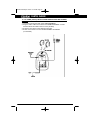
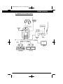
720 820 manual.qxd 12/4/01 10:16 AM Page 1
7” LCD Color Monitor
8” LCD Color Monitor
OWNER’S MANUAL
720 820 manual.qxd 12/4/01 10:16 AM Page 2
OHM720, OHM820
INTRODUCTION
The Clarion OHM720/OHM820 is a full-featured 7”/8” LCD Color Monitor that can
be used as a stand-alone monitor, or can be integrated into a mobile multimedia
system.
The OHM720/OHM820 has the following features:
l TFT Active Matrix Display
l Swivel Mechanism
l 16:9/4:3 Adjustable Wide Screen Format (OHM720 only)
l 2 RCA Composite Video Inputs
l 1 RCA Composite Video Output
l Lightweight Plastic Housing
l Built-In Dome Light
l Built-In IR Transmitter for Wireless Headphones
l Front Panel Power Indicator and Separate Power, Channel Up/Down, Aux,
FM Modulator and Picture Mode Button Controls
l FM Modulator Output Connector (for FM200 Add-On's)
l Includes Universal Mounting Bracket and Two IR Wireless
Headphones (WH100H)
l IR Remote Controls Monitor Functions, Optional VCR (VDH910)
and Optional TV Tuner (TTX001) Functions
l Includes Ribbon Cable (for TTX001 TV Tuner Add-On's)
ABOUT THE MANUAL AND WARRANTY
To start enjoying your new Clarion monitor, please read the instructions listed in
the manual. Keep all instructions for future reference. Also, save your original
sales receipt as proof of purchase.
TABLE OF CONTENTS
1. Precautions . . . . . . . . . . . . . . . . . . . . . . . . . . . . . . . . . . . . . . .
2. Description . . . . . . . . . . . . . . . . . . . . . . . . . . . . . . . . . . . . . . .
3. Package Contents . . . . . . . . . . . . . . . . . . . . . . . . . . . . . . . . . .
4. Monitor Button Functions . . . . . . . . . . . . . . . . . . . . . . . . . . . . .
5. Description of IR Remote Control . . . . . . . . . . . . . . . . . . . . . . .
6. Using Remote Control . . . . . . . . . . . . . . . . . . . . . . . . . . . . . . .
7. Inserting the Batteries . . . . . . . . . . . . . . . . . . . . . . . . . . . . . . .
8. Wiring Precautions . . . . . . . . . . . . . . . . . . . . . . . . . . . . . . . . .
9. Installation Instructions . . . . . . . . . . . . . . . . . . . . . . . . . . . . . .
10. Dome Light Wiring . . . . . . . . . . . . . . . . . . . . . . . . . . . . . . . . . .
11. Dome Light ON/OFF Switch Description . . . . . . . . . . . . . . . . .
12. Din Cable Pin Layout . . . . . . . . . . . . . . . . . . . . . . . . . . . . . . . .
13. Picture Adjustments . . . . . . . . . . . . . . . . . . . . . . . . . . . . . . . . .
14. FM Modulator (FM200) System Diagram . . . . . . . . . . . . . . . . .
15. TV Tuner (TTX001) Installation Instructions
and System Diagram . . . . . . . . . . . . . . . . . . . . . . . . . . . . . . . .
16. Complete A/V System Diagram . . . . . . . . . . . . . . . . . . . . . . . .
17. Care and Maintenance . . . . . . . . . . . . . . . . . . . . . . . . . . . . . .
18. Specification . . . . . . . . . . . . . . . . . . . . . . . . . . . . . . . . . . . . . .
19. Warranty Information . . . . . . . . . . . . . . . . . . . . . . . . . . . . . . . .
1
.
.
.
.
.
.
.
.
.
.
.
.
.
.
.
.
.
.
.
.
.
.
.
.
.
.
.
.
.
.
.
.
.
.
.
.
.
.
.
.
.
.
2
2
2
3
3
5
5
5
6
7
7
7
8
8
.
.
.
.
.
.
.
.
.
.
. 9
. 10
. 11
. 11
. 12
720 820 manual.qxd 12/4/01 10:16 AM Page 3
OWNER’S MANUAL
1. PRECAUTIONS
l
l
l
l
l
l
l
l
l
The set is for use in DC 12V, negative ground vehicles.
Do not operate the set in ways other than described in this guide.
Doing so may damage it and voids your warranty.
SAFETY FIRST! For rear seat use only. Do not install in dashboard or
anywhere else that would permit monitor to be viewed by the driver.
Monitor must never be used in any manner that will distract driver or
interfere with the driver's safe operation of the motor vehicle.
Be careful not to run down the car battery while using the set with the car
stopped.
Do not disassemble or modify the set. Doing so may damage it and voids
your warranty.
Keep drinks and drops from umbrellas away from the set.
Water may damage the internal circuitry.
Do not let the set become hot. If temperature in the car is high or the set
has been exposed to direct sunlight and is hot, lower the temperature
before using it. (The liquid crystal panel will work properly within a
temperature range of 14°F - 144° F).
In extremely cold temperatures, the movement of the picture may be slow
and the picture may be dark, but this is not a malfunction. The set will
work normally once the temperature increases.
Small black and shiny dots inside the liquid crystal panel are normal for
liquid crystal product.
2. DESCRIPTION
The OHM720/OHM820 is a TFT active matrix color LCD monitor that delivers a
striking picture and superior image resolution. The OHM720/OHM820 can be
used to enjoy video images with the Clarion video sources, even if no TV tuner
is connected.
3. PACKAGE CONTENTS
DESCRIPTION
LCD Monitor
IR Headphones (WH100H)
Universal Trim Ring
IR Remote Control
A/V Din Cables
TV Input Ribbon Cable
FM Modulator Din Cable
Power Connector
M3X8 Screws
Manual/Installation Guide
Q’TY
1
2
1
1
2
1
1
1
5
1
2
720 820 manual.qxd 12/4/01 10:16 AM Page 4
OHM720, OHM820
4. MONITOR BUTTON FUNCTIONS
1
Monitor Release Button
2
3
Dome Light Switch
Power Button
4
Channel Select Up
5
6
Channel Select Down
Mode Selector
7
FM Modulator On/Off Button
8
9
Auxiliary Input Selector
Power LED
10
5. DESCRIPTION OF IR REMOTE CONTROL
Button Functions
3
IR Sensor
720 820 manual.qxd 12/4/01 10:17 AM Page 5
OWNER’S MANUAL
1 Power Button for Monitor
Powers on monitor
2 TV/Video Button
Switches between A/V1, A/V2, TV.
3 FM Modulator Button
Turns FM Modulator ON/OFF.
4 Auto Memory Button for TTX001 (TV Tuner)
Locks channels with good reception.
5 Channel Up for TTX001 (TV Tuner)
Changes TV channels up.
6 Channel Down for TTX001 (TV Tuner)
Changes TV channels down.
7 Picture Select Button for Monitor
Goes into picture mode menu for Monitor to select Contrast, Brightnesss, Color,
Tint and Wide Screen Mode.
8 Picture Mode Up Button
Adjusts selected picture mode.
9 Picture Mode Down Button
Adjusts selected picture mode.
10 TV Tuner/VCR Button for VDH910 (VCR)
Changes input source selection from VCR to TV Tuner.
11 Enter Button for VDH910 (VCR)
Toggles between selection of the On-Screen Menu choice.
12 Menu Button for VDH910 (VCR)
Displays the On-Screen Menu, or changes and exits the On-Screen Menu.
13 Power Button for VDH910 (VCR)
Powers the unit ON or OFF.
14 FF Button for VDH910 (VCR)
Press FF to fast forward the tape.
15 Play Button for VDH910 (VCR)
Press button to play the videocassette.
16 REW Button for VDH910 (VCR)
Press REW to rewind the tape.
17 Skip Button for TTX001 (TV Tuner)
Will skip through channels with no reception.
18 Shift Button for TTX001 (TV Tuner)
Changes menu selection.
19 Stop Button for VDH910 (VCR)
Press to stop any play, fast forward, or rewind mode.
20 Still/Slow Button for VDH910 (VCR)
Press once to pause for STILL frame. Press again to advance frame by
frame. Press and hold button for SLOW motion playbacks.
21 Channel Track DOWN Button for VDH910 (VCR)
In TV Tuner mode, changes TV Channels down.
22 Channel Track UP Button for VDH910 (VCR)
In TV Tuner mode, changes TV Channels up.
4
720 820 manual.qxd 12/4/01 10:17 AM Page 6
OHM720, OHM820
6. USING REMOTE CONTROL
Inside the vehicle, simply aim the IR Remote Control directly at the OHM720/
OHM820, or at a Clarion monitor, or video source with an IR eye input and
press any desired button for better results. Also note the following:
l Aim the IR Remote Control from no further than 7 feet away and no more
than 3 feet on either side of the sensor.
l Direct sunlight or very bright light will reduce sensitivity to the IR remote
signal commands. Be sure the monitor is not located in direct sunlight.
l Objects between the monitor will interfere or block IR remote signal
commands.
7. INSERTING THE BATTERIES
1. Locate the battery compartment on the back of the IR Remote Control.
2. Remove the battery holder and insert two AAA alkaline batteries matching
polarity as shown inside the battery holder.
3. Snap the battery holder back into the remote unit until it locks with a click.
8. WIRING PRECAUTIONS
Read all wiring precautions. If you are not sure of the connections, contact
your authorized Clarion dealer.
1. Disconnect the negative (-) lead of the battery before making any power
connections.
2. When creating passage holes for the power wires, use grommets to
eliminate any sharp edges created during drilling. This will protect the wire
from being nicked and causing a short circuit.
3. When connecting the ground lead, fasten the ground lead (black wire)
securely to a clean metal plate on the vehicle.
NOTE: The OHM720/OHM820 monitor displays video images only. It does not
provide audio output. Refer to the owner's manual of the connected device for
the information on audio output.
5
720 820 manual.qxd 12/4/01 10:17 AM Page 7
OWNER’S MANUAL
9. INSTALLATION INSTRUCTIONS
The OHM720/OHM820 is an overhead, flip-down 7"/8” monitor with an
infrared (IR) eye. It will accept a video signal from any video source with
composite video out. The IR eye will work directly with any Clarion video
source product with an IR Eye Input.
1. Look over the vehicle for a location for the monitor. Each vehicle is
different and locations will vary. Make sure the monitor will not interfere
with the driver.
2. Run necessary wires to the mounting location. When necessary cut the
headliner and pull wires through.
3. Use a 12"W x 12"L x ½" or ¾" thick piece of plywood to mount the
OHM720/OHM820.
4. Silicone the piece of plywood to the top of the roof or screw the plywood to
the dome light mounting assembly and or the roof support rail.
5. Once the plywood has been mounted, connect the IR, power and DIN
cables to the designated sources.
6. Make sure all wires and DIN cables are way from screws when drilling.
7. Screw the monitor and universial pod assembly (factory pre-assembled)
into the plywood using 4 wood screws (not supplied). Use the shortest
screws possible to prevent roof penetration.
6
720 820 manual.qxd 12/4/01 10:17 AM Page 8
OHM720, OHM820
10. DOME LIGHT WIRING
Negative Trigger Door Switch
Brown: + 12V
Gray: Ground
White: Door Switch
Positive Trigger Door Switch
Brown: Ground
Gray: + 12V
White: Door Switch
11. DOME LIGHT ON/OFF SWITCH DESCRIPTION
A three-position slide switch controls the lights integrated into the OHM720/
OHM820. Sliding the switch to the ON position will turn the lights on. The
OFF position will prevent the lights from turning on at all times, and the auto
position will allow the lights to turn on and off with the vehicle interior lighting.
Do not leave the vehicle unattended with the dome light switch in the ON
position, as this could result in a discharged battery.
12. DIN CABLE PIN LAYOUT
7
720 820 manual.qxd 12/4/01 10:17 AM Page 9
OWNER’S MANUAL
13. PICTURE ADJUSTMENT
To adjust the picture use the mode button to select the mode feature you
would like to adjust. Adjustment selections are as follow:
l Contrast
l Brightness
l Color
l Wide screen ON/OFF (OHM720 only)
l Tint
Press the up button to increase and the down button to decrease.
14. FM MODULATOR (FM200) SYSTEM DIAGRAM
8
720 820 manual.qxd 12/4/01 10:17 AM Page 10
OHM720, OHM820
15. TV TUNER (TTX001) INSTALLATION INSTRUCTIONS AND SYSTEM
DIAGRAM
1. Insert the tuner into the back of the OHM720/OHM820.
2. Plug the ribbon cable into the back of the OHM720/OHM820. Connect
another side of this cable to the TV Tuner (TTX001)
3. Screw the tuner down to the existing tuner holes.
4. Screw on the Clarion TV Tuner antenna ZCB001 OR ZCB003
(not included).
9
720 820 manual.qxd 12/4/01 10:17 AM Page 11
OWNER’S MANUAL
16. COMPLETE A/V SYSTEM DIAGRAM
10
720 820 manual.qxd 12/4/01 10:17 AM Page 12
OHM720, OHM820
17. CARE AND MAINTENANCE
Cleaning the cabinet
l Use a soft, dry cloth to gently wipe off any dirt.
l Do not use benzene, thinner, car cleaner, etc., as these substances may
damage the cabinet or cause the paint to peel.
Cleaning the LCD panel
l Use a soft, dry cloth to gently wipe off any dust.
l The surface is easily scratched; do not rub it with hard objects.
18. SPECIFICATIONS
General Specifications
Power Source:
Power Consumption:
Max Current Consumption:
OHM720 Dimensions:
OHM820 Dimensions:
OHM720 Weight:
OHM820 Weight:
Operating Temperatures:
Car Battery (DC 9-16V)
DC 12V 15W (without Dome lights)
Less than 1.5A (without Dome lights)
8-1/2" x 11-3/4" x 1-3/16" (W x H x D)
216 x 300 x 31.5 mm (W x H x D)
9-1/8" x 13-3/16" x 1-3/16" (W x H x D)
232 x 336 x 31.5 mm (W x H x D)
3 lb (1.4 kg)
3.5 lb (1.6 kg)
14°-140° F
Monitor Specification
Display Type
Color TFT Active Matrix LCD
OHM720 Display Screen size 7.0"
OHM820 Display Screen size 8.0"
Format
1440 x 234
Screen Resolution
336,960 dots
Video Signal
1Vp-p with 75-ohm load
Video System
Auto NTSC/PAL
11
720 820 manual.qxd 12/4/01 10:17 AM Page 13
OWNER’S MANUAL
19. WARRANTY INFORMATION
This product is warranted against all defects in material workmanship for a period of one
year from the date of original purchase. Clarion Multimedia products are covered by a
one-year warranty when installed by an authorized Clarion dealer. The conditions of this
warranty and the extent of responsibility of Clarion Corporation under this warranty are as
follows:
1. PROOF OF DATE OF PURCHASE WILL BE REQUIRED FOR WARRANTY SERVICE
OF THIS PRODUCT. IN CASE OF 1-YEAR WARRANTY FOR CLARION MULTIMEDIA
PRODUCT, PROOF OF INSTALLATION BY AUTHORIZED DEALER IS REQUIRED.
INFORMATION ABOUT CLARION AUTHORIZED WARRANTY SERVICE CENTERS
MAY BE OBTAINED BY CONTACTING OR WRITING CLARION CORPORATION AT
THE ADDRESS LISTED BELOW.
2. This warranty will become void if service performed by anyone other than an approved
Clarion Warranty Service Center results in damage to product.
3. This warranty does not apply to any product which has been subject to misuse, neglect
or accident, or which has had the serial number altered, defaced or removed, or which has
been connected, installed, adjusted or repaired, other than in accordance with the instruc tions furnished by Clarion Corporation.
4. This warranty does not cover car static or other electrical interferences, tape head
cleaning or adjustments, or labor costs for the removal or reinstallation of the unit for
repair.
5. The sole responsibility of Clarion Corporation under this Warranty shall be limited to the
repair or replacement thereof, at the sole discretion of Clarion Corporation.
6. If it becomes necessary to send the product or any defective part to Clarion
Corporation or an authorized warranty service station, the product must be shipped in its
original carton or equivalent carton, fully insured, with shipping charges prepaid. Clarion
Corporation will not assume any responsibility for any loss or damage incurred in shipping.
7. ALL IMPLIED WARRANTIES EXCEPT TO THE EXTENT PROHIBITED BY APPLICABLE LAW SHALL HAVE NO GREATER DURATION THAN THE WARRANTY PERIOD
SET FORTH ABOVE. UNDER NO CIRCUMSTANCES SHALL CLARION CORPORATION
BE LIABLE FOR ANY LOSS OR DAMAGE, DIRECT OR CONSEQUENTIAL, ARISING
OUT OF THE USE OR INABILITY TO USE THE PRODUCT. BECAUSE SOME STATES
DO NOT ALLOW LIMITATIONS ON HOW LONG AN IMPLIED WARRANTY LASTS OR
EXCLUSIONS OR LIMITATIONS OF INCIDENTAL OR CONSEQUENTIAL DAMAGES,
THE ABOVE LIMITATIONS OR EXCLUSIONS MAY NOT APPLY TO YOU.
8. THIS WARRANTY GIVES YOU SPECIFIC LEGAL RIGHTS, AND YOU MAY ALSO
HAVE OTHER RIGHTS WHICH VARY FROM STATE TO STATE.
9. For instructions on how to obtain warranty service, please call 1-800-GO-CLARION or
visit our web site at www.clarion.com for a listing of Authorized Warranty Service Centers
in your area, or contact the Clarion Customer Service Manager at the address listed
below:
Clarion Corporation of America
Attn: Customer Service Manager
661 W. Redondo Beach Blvd
Gardena, Ca. 90247-4201
12
720 820 manual.qxd 12/4/01 10:17 AM Page 14
661 West Redondo Beach Blvd.
Gardena, CA 90247
1-800-GO-CLARION
www.clarion.com
OHM720-820 Rev.0 (12/01)