1
User’s Manual
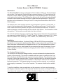
Custom Sensors Model CCD8000 Scanner
Introduction
The Model CCD8000 Scanner is designed for Point of Sale or Office use. Three interfaces
are provided. The Keyboard Wedge interface connects between a PC keyboard and the
computer console. When scanned, the characters in the barcode appear as though they
were typed on the keyboard. The USB interface behaves like the keyboard wedge, except it
connects to the computer through its USB port, rather than the keyboard port. The RS-232
interface can be connected to a Com: port on a PC or any other device with an EIA/TIA RS232C interface.
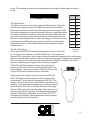
The Scanner has a wide reading aperture and is designed to operate in contact with, or
close to, the barcode symbol being scanned. The scanner can be up to ¾ inch from the
code. When the switch is pressed, the light source illuminates the barcode. The code is
read and decoded, a beeper sounds and the indicator light flashes. The illumination is then
extinguished. This process normally takes less than a second .
The unit will read barcodes up to 3 inches long. Most common linear barcode symbologies
are supported, including EAN/UPC, Code39, Code128, Codabar, Interleaved 2 of 5, Industrial 2 of 5, Matrix 2 of 5, DataLogic 2 of 5, Code93, IATA, MSI/Plessey, and Code11.
Installation
The three standard interfaces, Keyboard Wedge, USB and RS-232 are accomplished
through the use of seperate cable assemblies. When a unit is ordered with one of these interfaces, the proper cable assembly is shipped with the unit. The cable assemblies contain a
telephone-type connector, which mates with a connector at the rear of the scanner. It is possible to change the scanner’s interface by changing the cable. Cables are available from
Custom Sensors.
The Keyboard Wedge Interface.
The model with the keyboard wedge interface connects between the keyboard and the
console of the computer. This model is available with two types of connectors; the 5-pin
DIN or the 6-pin mini-DIN. Both units connect in the same manner. Turn off power to the
computer. Unplug the keyboard cable. Plug the keyboard cable into the female connector
on the scanner cable. Plug the male connector on the scanner cable into the computer
keyboard connection. The scanner derives its power from the computer, so no external
power supply is necessary. Turn on the Computer. The scanner should emit an audible
tone.
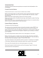
To test the installation, start an application on the computer, such as a word processor,
that displays characters typed on the keyboard. Review the section on Using CCD Scanners, later in this manual, if necessary. Scan the barcode below. The scanner should emit
1-1
a tone. The characters in the barcode should appear as though they were typed on the keyboard.
S
C
A
N
N
E
R
T
E
S
T
The USB Interface.
The USB model will connect to the computers USB interface. Plug in the
unit with the computer running. The USB model uses Human Interface
Device Drivers that are built into any operating system that supports USB.
During the installation you may be prompted to insert you operating system
disk. After installation is complete, check Windows Device Manager. You
should find a listing for Human Interface Devices, and the scanner will be
listed as a human interface Device under that category. The barcode scanner will emulate a USB keyboard. In operation it will act just like the Keyboard wedge model. Test the USB interface like the Keyboard Wedge
interface above.
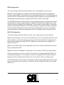
PIN
Name
1
Shld
2
TxD
3
RxD
4
N/C
5
GND
6
N/C
7
CTS
8
RTS
9
+5V
Connector
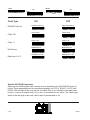
The RS-232 Interface.
Wiring.
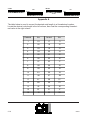
The model with the RS-232 interface is designed to connect to the Com:
port of a Personal Computer, or other RS-232 Device. The connector is
wired in DCE configuration. It will connect to the port without the requirement for a null-modem
cable. An external power supply is required, since there is no power available from a standard
RS-232 connector. An accessory power supply, Model APS002 is available from Custom
Sensors. If another power supply is used, it must be regulated
5VDC±10% @ 200 milliamps minimum and must have a
power connector that is 5.5mm outside diameter and 2.1mm
inside diameter. The center is positive. The RS-232 connector
is a type DB-9S and is wired as shown in the table.
Apply power to the scanner, but do not connect the RS-232
cable. The default mode of operation of this scanner is Keyboard wedge. The first task is to change this to RS-232. Turn
to page 2-4 of this manual. Scan the START code at the top of
the page. The scanner should respond by sounding a series of
tones. Scan the Use RS-232 Interface barcode on that page.
Scan the END code at the top of the page. The scanner is now
configured for RS-232 operation. The communications parameters are: 9600 Baud, 8 Data Bits, and No Parity. RTS/CTS
handshaking is disabled. These parameters can be changed
as outlined in part two of this manual.
1-2
Using CCD Scanners
The CCD Scanner reads barcodes through the elongated front opening in the scanner. The
scanner is normally placed on the code so that the code is centered in this opening. When the
button on the bottom of the scanner is pushed, the scanner light source is switched on and
illuminates the barcode. A CCD (Charge Coupled Device), similar to that used in digital
cameras, registers an image of the barcode. A microcomputer within the scanner decodes
this image into the characters represented by the barcode, and sends them to the Keyboard
Wedge or RS-232 Interface. An audible tone is heard, the illumination is turned off, and an
indicator on the scanner flashes when the code has been read. The button can then be released.
CCD scanners usually work in contact, or close contact, with the barcode. The easiest way to
align the scanner with the code is to place the rectangular opening over the barcode. In many
cases a useful technique is to place the scanner on the surface containing the barcode, so the
code can be seen above the top of the scanner. With the button pressed, move the scanner up
on to the code until the tone sounds indicating a good read. Even though this model will work
up to 0.75 inch from the barcode, it is usually easiest to use it in contact.
CCD Scanners differ from laser scanners in that they form an image of the code rather than
scanning it. CCD scanners have no moving parts and the light source does not require the
safety precautions associated with a laser.
Mechanical Specifications
Weight:
About 5 oz. (without cable)
Case:
ABS Plastic
Dimensions: See Drawing
1-3
TROUBLESHOOTING
The following items illustrate common problems encountered in the initial installation of the
CCD Scanner.
Common Scanning Problems
A barcode will not read, no tone is heard or indicator does not flash.
Make sure that the barcode is not wider than the scanner opening. Remember, the width of
the code also includes quiet zones, equal to 10 times the width of a narrow bar, at each
end of the code.
Make sure the code is approximately centered in the scanner opening.
Make sure that the scanner will read that barcode type, and that type is enabled. See Page
2-10 of this manual.
Make sure that the code is of reasonable quality in that the printing is not smeared an there
seems to be good contrast between the bars and spaces.
Keyboard Wedge Configuration.
Connectors will not fit the keyboard.
The scanner can be ordered with the two most popular connectors used on IBM PC and
PC compatible keyboards; the 5-pin DIN connector and the 6-Pin mini-DIN connector. If
these connectors do not match your keyboard, check Page 2-2 of this manual to make sure
that this scanner will function with your keyboard. Adapters may be necessary to interface
to your keyboard.
The scanner beeps and the indicator flashes, but no data appears on the screen.
Make sure that the scanner is configured as a keyboard wedge. Since this is the default
interface, scan the SET code on the top of any even page of Section 2. Scan the codes for
the keyboard type and language on page 2-2. Scan the End Code.
Type a few characters on the keyboard to test the connection. If characters do not appear
on the screen, check each cable connection as well as the connection to the scanner.
Only some of the characters that are in the barcode appear on the screen.
Slow down the speed at which the data is sent from the scanner. Page 2-3 in the next
section shows how to accomplish this.
1-4
USB Configuration.
The scanner beeps and the indicator flashes, but no data appears on the screen.
Make sure that the scanner is configured as a keyboard wedge. Since this is the default
interface, scan the SET code on the top of any even page of Section 2. The USB interface is
actually a PS/2 to USB converter, so the scanner itself is configured for Keyboard Wedge. If
the scanner has somehow been configured for RS-232, it will not output data.
The CCD8000 emulates a USB keyboard. To an operating system it is considered a Human
Interface Device. If your operating system is Windows, the scanner will appear as a Human
Interface Device in Windows Device Manager. There should be similar entries for operating
systems such as Mac OS and Linux. If the scanner does not appear in the listing, unplug the
scanner and reboot the system. Plug in the scanner with the system running. You should receive an indication from the operating system that it is installing a Human Interface Device.
RS-232 Configuration
The scanner beeps and the indicator flashes, but no data seems to be transmitted.
Make sure the scanner is set up as an RS-232 device. Even if the scanner has the correct
cable installed, it must still be properly configured. Note that the default configuration for
the scanner is Keyboard Wedge. RS-232 configuration parameters are configured on
Pages 2-4 and 2-5.
Make sure the Baud Rate, Word Length and Parity of the scanner match the host device
being communicated with.
Make sure that the “handshake” requirements of the scanner and the host device agree.
Check the connection to the host device. The Scanner is configured as DCE (Data Communications Equipment). It can connect to a device configured as DTE (Data Terminal
Equipment) with a straight cable. Make sure a null-modem cable is not being used.
Use a breakout box or other tester to determine if data is being transmitted from the scanner and not being received properly. This device will also indicate the status of the handshake lines.
1-5
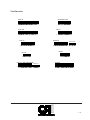
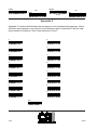
Test Barcodes
Interleaved 2 of 5
Code 39
A
B
C
D
1
2
3
UPC-A
Code 128
T e
s
t
$ C o d e
0
12345 12345
EAN-13
Bookland
2 512345 123453
9 781568 849294
0
012490
51999
2312 4905
0
UPC w/ 5 digit supplemental
12345
12345 12345
0
EAN-8
UPC-E
0
1234567890
4
0
Codabar
A 1 2 3 4 5 6 7 8 9 0 D
1-6
Scanner Configuration
Introduction
The Custom Sensors CCD8000 Series scanners can be configured by scanning the
barcodes in this manual. There are four special barcodes that are used in the configuration
process. These are the Start, End, Abort and Set codes. These codes appear at the top of
every even page so that they are readily available at any point in the configuration process.
Their function is as follows:
The START code begins the configuration process. It signals the scanner that the
Configuration Mode is being entered and that barcodes it will be reading are the
barcodes in this manual.
The ABORT code signals the scanner to disregard any configuration changes made
since the START code was scanned, as long as the END code has not been
scanned. In effect, it ends the Configuration process with no changes made. To start
again scan the START code.
The END code ends the Configuration process and returns the scanner too its
normal operating mode.
The SET code sets all scanner parameters to their default values. Unless the scanner was ordered with a special configuration, this resets the scanner to the configuration it contained when it was received. Notice that each parameter listed in this
manual has a default value. This code can be scanned at any time. The START
code does not have to be scanned first.
The Default Configuration is as Follows:
Keyboard Wedge Interface
IBM PC/AT and PS/2 series Computers
US Keyboard Layout
Code 39, Codabar and EAN/UPC codes enabled
Read Mode: Trigger on/Good Read off
Good Read beep active
Keyboard number keys: alphanumeric
Preamble and Postamble: None
Each of the above parameters will be explained in the following Sections of this Manual.
CFT-A
2-1
START
ABORT
END
SET
END
SET
START
ABORT
The Scanner Communications Settings.
The scanner has three communications methods. The Default is Keyboard Wedge interface. The USB interface is actually a PS/2 to USB converter attached to a Keybaard
Wedge scanner, so it should be treated as a Keyboard Wedge interface. The other is RS232. The Keyboard Wedge/USB will be listed first.
Keyboard Wedge/USB Parameters
Select the type of keyboard being used. The Default is the PC/AT and PS/2 Models 50, 60
and 80. The USB interface must use this setting. A Keyboard Wedge scanner can use any
of the other available types.
PC/AT PS/2-50/60/8
Thinkpad
PC/XT
IBM5550
ACER 7300
Macintosh (ADB)
NEC 9800
Select the keyboard layout from one below. The Default is the US keyboard.
US
Germany
French
Swiss
2-2
Spanish
UK
CFT-A
The wedge can send alpha characters as either upper case or lower case. Default is lower
case. This does not apply to full ASCII codes, such as Extended Code 39 or Code 128.
Upper
Lower
The number keys option controls whether the wedge sends numbers as the keys on the top
row of the keyboard (Default), or as the keypad keys. Some programs are designed to
receive numeric input only from the keypad. Note: The Num Lock must be enabled if the
keypad is used.
Keyboard
Keypad
The speed at which the barcode data is sent to the keyboard port can be changed. By
default, data is sent at the fastest rate. The rate can be slowed using the codes below.
Scan the START code on Page 2, one of the codes below, then the END code on Page 2.
Fastest (Default)
Fast
Slow
Slowest
CFT-A
Medium
2-3
START
ABORT
END
SET
END
SET
START
ABORT
RS-232 Parameters
To set the Scanner to RS-232 communications, scan the code below. Note that in order for
the scanner to function in this mode it must be equipped with the RS-232 cable and will
also require an external power supply. To return to the keyboard wedge mode, scan the
“Return to Wedge” code below.
RS-232
Return to Wedge
After Selecting RS-232, select the desired baud rate. Note that the default communications
parameters are: 9600 baud, 8 data bits, No Parity, 1 Stop Bit.
1200 baud
2400 baud
4800 baud
9600 baud
19200 baud
38400 baud
Select the number of data bits. Both 7 and 8 bit data words are available.
7 Bit Word
8 Bit Word (Default)
Select parity from the choices below. Normally No parity is used with an 8 bit data word.
Mark, Space, Even or Odd parity is selected for a seven dit data word.
No Parity (Default)
2-4
Even Parity
Odd Parity
CFT-A
Select a Handshaking protocol. These protocols involve the use of the RTS and CTS
control signals. Select None if RTS/CTS will not be used. RTS will be driven high (True)
when the scanner is powered on. The CTS line will be used to control data transmission.
That is, data will only be transmitted when CTS is true. The Xon/Xoff software protocol is
also available to control data transmission. When using this protocol, remember that the
scanner cannot buffer multiple reads.
None (Default)
CFT-A
RTS/CTS
Xon/Xoff
2-5
START
END
ABORT
SET
END
SET
START
ABORT
General Parameters
This Section sets some general configuration parameters that are independent of the type
of interface being used.
Select a Terminator Character(s) to be used in the data transmission. The terminator is
always transmitted last and indicates the end of transmission. In RS-232 a CR (Carriage
Return) is most often used. With the keyboard wedge interface, a TAB is often used to
send the cursor to the next data field.
None
LF (RS-232 Only)
CR (Default)
Space
CR/LF (RS-232 Only
Esc
Tab
Ctrl-C
An ID Character can be assigned to each code type. ID characters are used in situations
where the scanner may be reading several barcode types and it is desired to know which
type was read. A single ID character, which can be any ASCII character, can be assigned
to any or all code types. The character will be transmitted, immediately preceding the
barcode data, as part of the keyboard wedge or RS-232 transmission. To assign a character, scan START and then scan one of the codes below that corresponds to the code type
to which the identifier will be assigned. Next, turn to the Appendix B Find the Hex value of
the identifier character. Then turn to Appendix C and scan the barcodes for the two numbers of the Hex value. Scan the Set code in Appendix C. Scan the END Code at the top of
any page.
Code 39
Industrial 2 of 5
Interleaved 2 of 5
Codabar
EAN-8
UPC-A/EAN-13
2-6
Matrix 2 of 5
UPC-E
CFT-A
Code 11
Code 128
MSI/Plessey
Up to a 10 character long Preamble and Postamble may be specified as part of the data
transmission. The Preamble field is transmitted before the barcode data. The Postamble
field will be transmitted after the barcode data. If an ID character is specified the default
order of transmission will be: Preamble Field - Code ID Character - Barcode Data Postamble Field - Terminator Character(s). If an ID or Terminator is not specified they are
deleted from the transmission.
To define a Preamble, scan Start and then the Define Preamble label below. Proceed to
Appendix B, and look up the Hexadecimal Value for each character that will be in the preamble. For example: if the preamble were “abc”, the Hex Values would be 61, 62 and 63.
Proceed now to appendix C. Scan the barcode for 6, then 2, then 6, then three, then 6 and
finally 3. Scan the Set code at the bottom of the page. Scan the END code at the top of any
page. The Postamble field is programmed identically to the Preamble.
Define Preamble
Define Postamble
Several different Operation Modes may be selected. To select a mode, scan the START
code at the top of any page. Scan the code corresponding to that mode, then scan the
END code. These modes are:
Trigger On/Off - The time that the light source will be on and the scanner reading, is controlled directly by the trigger switch. Closing the switch will let scanner read. As soon as a
good read occurs, the data is transmitted and the tone sounds. The light will remain on until
the switch is released.
Trigger On.Off
CFT-A
2-7
START
END
ABORT
SET
END
START
SET
ABORT
Trigger On / Good Read Off - The trigger switch controls the start of the reading process.
When the trigger is pressed, the light source is turned on. When a good read is achieved,
the light is turned off and the data is transmitted. If a read has not been made within 3
seconds, the light is turned off and no transmission is made. This is the default mode of
operation.
Trigger ON
Direct Trigger Control - The light source is turned on and the scanner is enabled to read by
pressing the trigger switch. The trigger must be released and pressed again to end the
reading process.
Direct Trigger Contro
Always On - Pressing the trigger switch will turn the light source on and start the reading
process. Once a code is read, a different code must be seen ( or the same code removed
from the scanners view) before another read will occur.
Always On
Always On Continuous reading - Pressing the trigger switch will turn the light source on and
start the reading process. The scanner will output data every time it successfully decodes a
barcode.
Continuous Reading
2-8
CFT-A
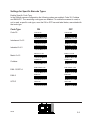
Settings for Specific Barcode Types.
Enable Specific Code Type.
In the Default scanner configuration the following codes are enabled: Code 39, Codabar
and EAN/UPC. The remaining code types are disabled. To enable the scanner to read, or
not to read, a specific code type, scan the ON or OFF barcode label below, associated with
that code type.
Code Type
Code 39
ON
OFF
Code 39 On
Code 39 Off
Interleaved 2 of 5 On
Interleaved 2 of 5 Of
Industrial 2 of 5 On
Industrial 2 of 5 Off
Matrix 2 of 5 On
Matrix 2 of 5 Off
Codabar On
Codabar Off
EAN-13/UPC-A On
EAN-13/UPC-A Off
EAN-8
EAN-8 On
EAN-8 Off
UPC-E
UPC-E On
UPC-E Off
Interleaved 2 of 5
Industrial 2 of 5
Matrix 2 of 5
Codabar
EAN-13/UPC-A
CFT-A
2-9
START
END
ABORT
SET
END
SET
START
Code Type
EAN/UPC Add-on
Code 128
ABORT
ON
OFF
EAN/UPC Add-on O
EAN/UPC Add-on O
Code 128 On
Code 128 Off
Code 11 On
Code 11 Off
MSI/Plessey On
MSI/Plessey Off
Datalogic 2 of 5 On
Datalogic 2 of 5 Off
Code 11
MSI/Plessey
DataLogic 2 of 5
Specific UPC/EAN Parameters
Scanning the following barcodes controls various parameters for the EAN/UPC family of
codes. These parameters can be controlled separately for UPC-A, EAN-13, UPC-E and
EAN-8. The first digit of the code can be truncated, that is, not included in the data transmission. It can be truncated only if it is a zero, or truncated for any value. The Check digit,
which is the last digit in the code, can be also be transmitted or not.
2-10
CFT-A
For EAN-13:
Truncate Leading Digit
No
Yes
Truncate Leading Zero
Yes
No
Transmit Check Digit
Yes
No
For UPC-A:
Truncate Leading Digit
Yes
No
Truncate Leading Zero
Yes
No
Transmit Check Digit
Yes
No
For EAN-8:
Truncate Leading Digit
Yes
No
Transmit Check Digit
Yes
CFT-A
No
2-11
START
END
ABORT
SET
END
SET
START
ABORT
For UPC-E:
Truncate Leading Digit
Yes
No
Transmit Check Digit
Yes
No
Specific Code 39 Parameters.
This Section configures parameters associated with the Code 39 barcode type.
There are two types of Code 39, the Standard and Full ASCII versions. The standard
version encodes the numbers 0 thru 9, the upper case letters A thru Z and the characters:
space, -, ., *, $, /, + and %. The Full ASCII, or extended, version encodes all 128 ASCII
characters. The additional, or extended, characters are encoded as character pairs, resulting in a longer code.
The Start and Stop characters, which are the asterisk (*) character, can be transmitted
along with the other characters in the code.
Code 39 may be printed with a check digit. If so, this scanner has the options of calculating
the check and transmitting it as part of the data transmission. If the check digit calculation
fails, no transmission is made.
Code Type
Standard Code 39
Full ASCII Code 39
Transmit Start Stop Characters
Yes
2-12
No
CFT-A
Verify Check Character
Yes
No
Transmit Check Character
Yes
No
Interleaved 2 of 5 Code Parameters.
For the Interleaved 2 of 5 code type can be printed with a check digit. The scanner can be
programmed to verify that this check digit is correct. It can also be programmed to include
the check digit in the data transmission, if desired.
Because of certain characteristics of the Interleaved two of five code, it is recommended
that a fixed code lengths be used. This prevents problems of reading fewer characters than
are actually in the barcode. As the scanner is received, it is programmed to read any
length, up to 30 characters. Up to three fixed lengths can be programmed. To program a
fixed length, scan the “Define Length” barcode below. The length entered must be expressed as a Hexadecimal number, rather than decimal. Turn to the table in Appendix A to
convert the desired length to a Hexadecimal number. For example, for a length of 10, the
Hexadecimal number would be 0A. Next, turn to Appendix C. Scan the barcode for 0, then
the code for A. Make sure to only scan each code once. If an error occurs, scan the Abort
code above, and restart. Scan the Set code in Appendix C. Scan the End code at the top of
any page.
Yes
Transmit Check Digit
No
Verify Check Digit
Yes
No
Define Length
CFT-A
2-13
START
END
ABORT
SET
END
SET
START
ABORT
Industrial 2 of 5 Parameters
For the Industrial 2 of 5 code type can be printed with a check digit. The scanner can be
programmed to verify that this check digit is correct. It can also be programmed to include
the check digit in the data transmission, if desired.
Because of certain characteristics of the Industrial two of five code, it is recommended that
a fixed code lengths be used. This prevents problems of reading fewer characters than are
actually in the barcode. As the scanner is received, it is programmed to read any length, up
to 30 characters. Up to three fixed lengths can be programmed. To program a fixed length,
scan the “Define Length” barcode below. The length entered must be expressed as a
Hexadecimal number, rather than decimal. Turn to the table in Appendix A to convert the
desired length to a Hexadecimal number. For example, for a length of 10, the Hexadecimal
number would be 0A. Next, turn to Appendix C. Scan the barcode for 0, then the code for
A. Make sure to only scan each code once. If an error occurs, scan the Abort code above,
and restart. Scan the Set code in Appendix C. Scan the End code at the top of any page.
Transmit Check Digit
Yes
No
Verify Check Digit
No
Yes
Define Length
2-14
CFT-A
Matrix 2 of 5 Code Parameters
For the Matrix 2 of 5 code type can be printed with a check digit. The scanner can be
programmed to verify that this check digit is correct. It can also be programmed to include
the check digit in the data transmission, if desired.
Because of certain characteristics of the Industrial two of five code, it is recommended that
a fixed code lengths be used. This prevents problems of reading fewer characters than are
actually in the barcode. As the scanner is received, it is programmed to read any length, up
to 30 characters. Up to three fixed lengths can be programmed. To program a fixed length,
scan the “Define Length” barcode below. The length entered must be expressed as a
Hexadecimal number, rather than decimal. Turn to the table in Appendix A to convert the
desired length to a Hexadecimal number. For example, for a length of 10, the Hexadecimal
number would be 0A. Next, turn to Appendix C. Scan the barcode for 0, then the code for
A. Make sure to only scan each code once. If an error occurs, scan the Abort code above,
and restart. Scan the Set code in Appendix C. Scan the End code at the top of any page.
Transmit Check Digit
Yes
No
Verify Check Digit
No
Yes
Define Length
DataLogic 2 of 5 Code Parameters.
For the DataLogic 2 of 5 code type can be printed with a check digit. The scanner can be
programmed to verify that this check digit is correct. It can also be programmed to include
the check digit in the data transmission, if desired.
Because of certain characteristics of the Interleaved two of five code, it is recommended
that a fixed code lengths be used. This prevents problems of reading fewer characters than
are actually in the barcode. As the scanner is received, it is programmed to read any
length, up to 30 characters. Up to three fixed lengths can be programmed. To program a
fixed length, scan the “Define Length” barcode below. The length entered must be ex-
CFT-A
2-15
START
END
ABORT
SET
END
SET
START
ABORT
pressed as a Hexadecimal number, rather than decimal. Turn to the table in appendix A to
convert the desired length to a Hexadecimal number. For example, for a length of 10, the
Hexadecimal number would be 0A. Next, turn to Appendix C. Scan the barcode for 0, then
the code for A. Make sure to only scan each code once. If an error occurs, scan the Abort
code above, and restart. Scan the Set code in Appendix C. Scan the End code at the top of
any page.
Transmit Check Digit
No
Yes
Verify Check Digit
Yes
No
Define Length
Specific Codabar Parameters
For the Codabar code type, there can be various sets of start and stop characters. In some
applications, the value of the start and stop characters are just as important at the barcode
data itself. Transmission of the start and stop characters, as well as the character sets
used, can be programmed by scanning the barcodes below.
Transmit Start and Stop Characters
Yes
NO
Start / Stop Character set.
2-16
ABCD / ABCD
ABCD / TN*E
abcd / abcd
abcd / tn*e
CFT-A
Specific Code 11 Parameters
Code 11 can be printed with either one or two check digits. The check digits are never
transmitted. Scanning the barcodes below programs the scanner to expect one or two
check digits. The scanner can verify that the check digits are correct, or ignore them.
Number of Check Digits
Two
One
Verify Check Digit
Yes
CFT-A
No
2-17
START
ABORT
END
SET
END
SET
START
ABORT
Appendix A
The table below is used to convert the desired code length to a Hexadecimal number.
Locate the desired code length in the left column, then read the corresponding Hexadecimal value in the right column.
2-18
Decimal
Hex
Decimal
Hex
1
01
17
11
2
02
18
12
3
03
19
13
4
04
20
14
5
05
21
15
6
06
22
16
7
07
23
17
8
08
24
18
9
09
25
19
10
0A
26
1A
11
0B
27
1B
12
0C
28
1C
13
0D
29
1D
14
0E
30
1E
15
0F
31
1F
16
10
32
20
CFT-A
Appendix B
Use Appendix B to enter Preamble and Postamble field. Each character in the Preamble or
Postamble must be entered as a two character Hex value. Look up the value of each
character in the Table below.
CFT-A
Character
Hex Value
Character
Hex Value
Character
Hex Value
S p a ce
20
A
41
b
62
63
!
21
B
42
c
"
22
C
43
d
64
#
23
D
44
e
65
$
24
E
45
f
66
%
25
F
46
g
67
&
26
G
47
h
68
'
27
H
48
i
69
(
28
I
49
j
6A
)
29
J
4A
k
6B
*
2A
K
4B
l
6C
+
2B
L
4C
m
6D
,
2C
M
4D
n
6E
-
2D
N
4E
o
6F
70
.
2E
O
4F
p
/
2F
P
50
q
71
0
30
Q
51
r
72
1
31
R
52
s
73
2
32
S
53
t
74
3
33
T
54
u
75
4
34
U
55
v
76
5
35
V
56
w
77
6
36
W
57
x
78
7
37
X
58
y
79
8
38
Y
59
z
7A
9
39
Z
5A
{
7B
:
3A
[
5B
|
7C
;
3B
\
5C
}
7D
<
3C
]
5D
~
7E
=
3D
^
5E
>
3E
_
5F
?
3F
`
60
@
40
a
61
7F
2-19
START
ABORT
END
SET
END
SET
START
ABORT
Appendix C
Appendix C contains the Barcodes that correspond to the Hexadecimal characters. Notice
that when any character is converted to a hexadecimal value in Appendix B, that the character consists of numbers 0 thru 9 and characters A thru F.
0
8
1
9
2
A
3
B
4
C
5
D
6
E
7
F
Set
2-20
CFT-A