1
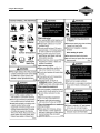
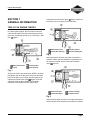
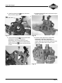
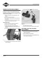
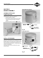
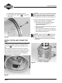
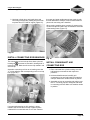
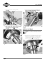
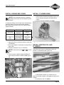
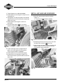
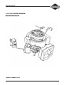
2-Cycle Snow Engine
2-CYCLE SNOW ENGINE
REPAIR MANUAL
MANUAL NUMBER: 276535
0
2-Cycle Snow Engine
SAFETY INFORMATION
The Briggs & Stratton engine is made of the finest
material in a state-of-the-art manufacturing facility.
Please understand that Briggs & Stratton sells engines
to original equipment manufacturers. It also sells to
others in the distribution chain who may sell to the
ultimate consumer, an equipment manufacturer, another
distributor or a dealer. As a result, Briggs & Stratton does
not necessarily know the application on which the engine
will be placed. For that reason, carefully read and
understand the operating instructions of the equipment
before you repair or operate.
You should also understand that there are equipment
applications for which Briggs & Stratton does not
approve the use of its engines. Briggs & Stratton engines
are not to be used on vehicles with less than 4 wheels.
This includes motor bikes, aircraft products and all
terrain vehicles. Moreover, Briggs & Stratton does not
approve of its engines being used in competitive events.
FOR THAT REASON, BRIGGS & STRATTON
ENGINES ARE NOT AUTHORIZED FOR ANY OF
THESE APPLICATIONS. Failure to follow this warning
could result in death, serious injury (including paralysis)
or property damage.
IN THE INTEREST OF SAFETY
The safety alert symbol ( ) is used to identify safety
information about hazards that can result in personal
injury.
A signal word (DANGER, WARNING, or CAUTION) is used
with the alert symbol to indicate the likelihood and the
potential severity of injury. In addition, a hazard symbol
may be used to represent the type of hazard.
DANGER indicates a hazard which, if not
avoided, will result in death or serious injury.
WARNING indicates a hazard which, if not
avoided, could result in death or serious injury.
CAUTION indicates a hazard which, if not
avoided, might result in minor or moderate injury.
CAUTION: When this signal word is used without the
alert symbol, it indicates a situation that could result in
damage to the engine.
i
• Prior to work, read and understand the section(s) of
this manual that pertain to the job. Follow all safety
warnings.
• Wear suitable eye protection.
• Prevent accidental starting by removing spark plug
wire from spark plug when servicing engine or
equipment. Disconnect negative battery terminal if
equipped with electric starting system.
• Periodically clean engine. Keep governor parts free
of dirt, grass and other debris which can affect
engine speed.
• Always use fresh gasoline. Stale fuel can gum
carburetor and cause leakage.
• Check fuel lines and fittings frequently for cracks or
leaks and replace if necessary.
2-Cycle Snow Engine
ii
2-Cycle Snow Engine
iii
2-Cycle Snow Engine
Table of Contents
2-CYCLE SNOW ENGINE
REPAIR MANUAL ..................................... 0
SAFETY INFORMATION ........................... i
In The Interest Of Safety ............................... i
SECTION 1
GENERAL INFORMATION ....................... 1
TWO-CYCLE ENGINE THEORY .................1
IGNITION COIL OPERATION ......................2
REWIND STARTER .....................................3
ELECTRIC START (OPTIONAL) .................3
RECOMMENDED MAINTENANCE
SCHEDULE ..................................................3
25 Hours .......................................................... 3
50 Hours .......................................................... 3
REPLACE SPARK PLUG .............................4
CLEANING THE EXHAUST SYSTEM .........4
SECTION 2
TROUBLESHOOTING .............................. 5
GENERAL TROUBLESHOOTING
INFORMATION ............................................5
Systematic Check ............................................ 5
Check Ignition .................................................. 5
Engine Misfires ................................................ 5
Check Carburetion ........................................... 6
Check Compression ........................................ 6
EQUIPMENT AFFECTING ENGINE
OPERATION ................................................6
Hard Starting, Kickback, or Will Not Start ........ 7
Vibration ........................................................... 7
Power Loss ...................................................... 7
STARTER MOTOR FAILS TO TURN .........7
Power not reaching product. ............................ 7
Starter switch malfunction. ............................... 7
Engine has seized. .......................................... 7
Starter motor has failed. .................................. 7
SECTION 3
ENGINE DISASSEMBLY ..........................9
REMOVE SHROUD .....................................9
REMOVE CARBURETOR ............................9
REMOVE FLYWHEEL ................................10
REMOVE OPTIONAL 120V STARTER ......10
REMOVE MUFFLER ..................................10
REMOVE IGNITION MODULE ...................11
ENGINE DISASSEMBLY ...........................11
SECTION 4
ENGINE OVERHAUL ..............................13
ENGINE INSPECTION & REPAIR .............13
Flywheel and Key ...........................................13
Bearings .........................................................13
Crankcase ......................................................13
Check Cylinder Bore ......................................13
Piston And Rings ............................................14
Piston Pin (Wrist Pin) And Connecting Rod .....4
CARBURETOR DISASSEMBLY ................15
CARBURETOR CLEANING &
INSPECTION ..............................................17
CARBURETOR ASSEMBLY ......................17
REWIND STARTER Replacement .............20
Rope Replacement .........................................20
(OPTIONAL) ELECTRIC STARTER
REPLACEMENT .........................................20
SECTION 5
ENGINE ASSEMBLY ..............................21
ASSEMBLE PISTON AND
CONNECTING ROD ..................................21
INSTALL PISTON RINGS ..........................21
Engine Model 84130 & 84230 ........................21
Engine Model 84330 .....................................21
iv
2-Cycle Snow Engine
Table of Contents
INSTALL PISTON AND
CONNECTING ROD ..................................22
INSTALL CONNECTING ROD BEARINGS 23
INSTALL CRANKSHAFT AND
CONNECTING ROD ..................................23
INSTALL OIL SEALS ..................................24
INSTALL CRANKCASE COVER ................25
INSTALL CYLINDER HEAD .......................25
INSTALL IGNITION COIL AND
FLYWHEEL ................................................25
INSTALL AIR VANE AND GOVERNOR .....26
INSTALL INTAKE MANIFOLD AND
CARBURETOR ..........................................27
CHECK GOVERNOR OPERATION ...........27
INSTALL MUFFLER ...................................28
INSTALL BLOWER HOUSING ...................28
SECTION 6
FINAL ADJUSTMENTS &
SPECIFICATIONS .................................. 29
GOVERNOR ADJUSTMENTS ...................29
SPECIFICATIONS ......................................30
COMMON SPECIFICATIONS ....................30
STANDARD AND REJECT DIMENSIONS 31
v
2-Cycle Snow Engine
Section 1 - General Information
SECTION 1
GENERAL INFORMATION
compresses the fuel mixture (Item
Figure 2) that is on
the bottom side of the piston in the crankcase.
TWO-CYCLE ENGINE THEORY
In a piston-ported engine, the fuel mixture enters the
crankcase through a port that comes directly from the
carburetor (commonly referred to as a “third port”), See
item
figure 1.
Intake Ports Closed
Third Port Closed
Exhaust Port Opening
Pressure Building Up
Fig. 2
Near the bottom of its travel, the piston uncovers the
pressure transfer port and allows this compressed fuel/
air mixture to expand into the combustion chamber
(Item
Figure 3).
Intake Ports Closed
Ignition
Third Port Open
Partial Vacuum
Fig. 1
At about 28° before top-dead-center (BTDC), the spark
plug ignites and forces the piston away from the spark
plug. As the piston moves away from the spark plug, it
exposes the exhaust port (Item
Figure 2) and the
expanding exhaust gases escape. As the piston
continues to move away from the spark plug, it
Intake Ports Open
Fresh Fuel Change
Exhaust Port Open
Third Port Closed
Fig. 3
Now the piston begins its travel in the opposite direction
and first closes off the transfer port and then the exhaust
Page 1
2-Cycle Snow Engine
Section 1 - General Information
port. As it continues, it compresses the fuel mixture in
the combustion chamber (Item
Figure 4).
voltage is converted by a rectifier into a DC signal, which
is then stored in a capacitor (Figure 6).
Fig. 6
Intake Ports Closed
Third Port Closed
Compression
Partial Vacuum
Fig. 4
IGNITION COIL OPERATION
The ignition coil system (Item
Figure 5) is
breakerless and contains electronic components that
replace mechanical points and related accessories (such
as a breaker cam, spark advance assembly, etc.).
When the silicone-controlled rectifier (SCR) is triggered,
up to 200 volts DC, stored in the capacitor, travels to the
spark coil. Here it is stepped up to as much as 25,000
volts and is discharged across the electrodes of the
spark plug (Figure 7).
Ignition timing (when the SCR is triggered) is determined
by the flywheel magnet and the keyways in the flywheel
and crankshaft. Damage to any of these parts will affect
the ignition timing.
Fig. 7
Ignition Coil Module
Fig. 5
As the flywheel magnet passes the ignition coil module,
an AC voltage is induced into the charge coil. This AC
Page 2
2-Cycle Snow Engine
Section 1 - General Information
At slower speeds, the flywheel magnet induces a smaller
charge in the trigger coil. This action triggers the (SCR),
enabling easier starting in a “retarded firing position”
-about 5° before top dead center (BTDC). See figure 8.
REWIND STARTER
The rewind starter operates through a retainer/friction
disc and two engagement dogs that extend from the
center of the rewind starter and engage the inside of the
starter hub on the flywheel. The engagement dogs
contact the starter hub when the rewind rope is pulled.
When the engine starts, the starter cup exceeds the
speed of the recoil starter causing the ramps on the
inside of the cup to contact the back side of the starter
dogs, pushing them inward. When the starter rope is
relaxed, spring tension retracts the dogs.
ELECTRIC START (OPTIONAL)
Pole Shoe
Starting Leg
Flywheel Rotation
Charging Leg
Crankshaft at 5° BTDC
Pole Shoe
The electric start models use a 120VDC starting system.
When the starter is supplied with voltage, the helical
shaft spins to force the pinion gear out on the shaft and
engage the ring gear (Figure 10).
Magnet
Fig. 8
At faster speeds (about 800 RPM), the flywheel magnets
induce a large enough charge in the trigger coil to trigger
the SCR in the “advanced firing position,” -about 28°
BTDC (Figure 9).
Fig.10
RECOMMENDED MAINTENANCE
SCHEDULE
25 Hours
• Clean/replace or re-gap spark plug
50 Hours
• Clean exhaust ports
• Check for fuel leakage
Flywheel Rotation
Charging Leg
Crankshaft at 25° BTDC
Running Leg 25°
Advanced
Fig. 9
Page 3
2-Cycle Snow Engine
Section 1 - General Information
REPLACE SPARK PLUG
Replace spark plug every year. Replace spark plug if
electrode is burned away or if the porcelain is cracked. A
spark plug that is dirty, pitted, carbon covered or has
worn electrodes may cause hard starting and/or poor
operation. Clean plug with a wire brush. Do not sand
blast. Use NGK BPMR 4A or equivalent. Set spark plug
gap (Figure 11) at .028-.032 in. (.71-.81mm). Torque spark
plug to 150-200 lb-in. (17-23 Nm).
2. Inspect exhaust port (Figure 13). If cleaning is
necessary, rotate piston to cover exhaust port,
and scrape carbon from exhaust port area. Use
wood only to clean this area.
BST01-83
Fig. 13
.28-.032 in.
(.71 - .81mm)
Fig. 11
CLEANING THE EXHAUST SYSTEM
1. Remove the muffler (Figure 12) by removing the
bolts
shown. Clean as needed.
BST01-82
Fig. 12
Page 4
3. Install the muffler and torque the bolts to 80 lb-in.
(9Nm).
2-Cycle Snow Engine
Section 2 - Troubleshooting
SECTION 2
TROUBLESHOOTING
observed at the tester gap, you may assume the ignition
system is functioning satisfactorily.
GENERAL TROUBLESHOOTING
INFORMATION
Most complaints concerning engine operation can be
classified as one or a combination of the following:
• Will not start
• Hard starting
• Lack of power
• Runs rough
• Vibration
NOTE: What appears to be an engine
malfunction may be a fault of the powered
equipment rather than the engine. If equipment is
suspect, see Equipment Affecting Engine
Operation.
Fig. 14
NOTE: Engines equipped with capacitive
discharge ignition system will still display spark
at tester with a partially or fully sheared flywheel
key. A partially sheared flywheel key will affect
ignition timing and engine performance.
Systematic Check
If the engine is hard starting or will not start and the
cause of malfunction is not readily apparent, perform a
systematic check in the following order:
• Ignition
• Carburetion
• Compression
This check-up, performed in a systematic manner, can
usually be done in a matter of minutes. It is the quickest
and surest method of determining the cause of failure.
Check Ignition
With stop switch in ON/RUN position and spark plug
installed, attach a #19368 ignition tester to the spark plug
lead and ground the other end of the tester as shown in
figure 14. Operate the starter. If a strong, steady spark is
If spark does not occur look for:
• Shorted stop switch
• Shorted ground wire
• Incorrect armature air gap
• Armature failure
Engine Misfires
If engine runs but misses during operation, a quick check
to determine if ignition is or is not at fault can be made by
installing Tool #19368 tester between the spark plug lead
and spark plug (Figure 15). A spark miss will be obvious
Page 5
2-Cycle Snow Engine
Section 2 - Troubleshooting
when the engine is running. If the spark looks good in the
tester but the engine misses, try a new spark plug.
Check Compression
Connect spark plug wire to long terminal of tester, Tool
#19368 and ground tester to engine with alligator clip.
To check compression, remove the spark plug and install
compression tester
(Figure 16).
WE NEED TO FIND A TESTER!
Fig. 15
NOTE: A leak at the cylinder crankcase
mounting surfaces or oil seals can create a lean
fuel mixture resulting in low power or a miss.
Check for leakage at these areas.
Check Carburetion
Before checking carburetion, be sure the fuel tank has
an ample supply of fresh, clean gasoline. Make sure
throttle and choke controls are properly adjusted.
If engine cranks but will not start, remove and inspect the
spark plug.
If plug is wet, look for:
• Over choking
• Water in fuel
• Float needle valve stuck open
• Fouled spark plug
If plug is dry, look for:
• Leaking carburetor mounting gaskets.
• Gummy or dirty carburetor, fuel filter, fuel lines or
fuel tank
• Float needle valve stuck shut
• Plugged fuel cap vent
A simple check to determine if the fuel is getting to the
combustion chamber through the carburetor is to remove
the spark plug and pour a small quantity of fuel
(1 teaspoon or 5 mil.) through the spark plug hole.
Replace the plug. If the engine fires a few times and then
stops, look for the same conditions as for a dry plug.
Page 6
Fig. 16
Crank the engine using the rewind starter. Continue
cranking until meter reading stabilizes. The meter
reading should be approximately 115 PSI. (7.9 bar). If
compression is below 80 PSI (5.5 bar), look for:
• Loose cylinder head bolts
• Blown head gasket
• Worn bore and/or rings
• Broken connecting rod
EQUIPMENT AFFECTING ENGINE
OPERATION
Frequently, what appears to be a problem with engine
operation, such as hard starting, vibration, etc., can be
caused by the equipment being powered rather than the
engine itself. Since many varied types of equipment are
powered by Briggs & Stratton engines, it is not possible
to list all of the various conditions that may exist. Listed
are the most common effects of equipment problems,
and what to look for as the most common cause.
2-Cycle Snow Engine
Section 2 - Troubleshooting
Hard Starting, Kickback, or Will Not Start
• Loose drive adapter(s) - Pulleys and adapters must
be tight to shaft. Also, check for partially sheared
flywheel key.
• Starting under load - ensure the unit is not engaged
when engine is started; if the unit is engaged, that it
does not pose an excessive load to the engine.
• Check choke for proper adjustment.
• Check interlock system (if equipped) for shorted
wires, loose or corroded connections, or defective
modules or switches.
Vibration
• Auger bent or out of balance.
• Worn drive pulley(s)
• Mounting bolts loose
• Check for partially sheared flywheel key.
Power Loss
• Bind or drag in unit - if possible, disengage engine
and operate unit manually to check for any binding
action.
STARTER MOTOR FAILS TO TURN
Power not reaching product.
• Plug another appliance into extension cord to
ensure cord is OK.
Starter switch malfunction.
• Check switch using a volt/ohmmeter set for
resistance. Ensure that there is continuity when the
switch is depressed.
Engine has seized.
• Verify that the engine turns over freely.
Starter motor has failed.
• If all the above conditions are checked and the
starter still fails to turn, it must be repaired or
replaced.
Page 7
2-Cycle Snow Engine
Section 2 - Troubleshooting
Page 8
2-Cycle Snow Engine
Section 3 - Engine Disassembly
SECTION 3
ENGINE DISASSEMBLY
3. Slide the air vane from its mounting bracket
shown (Figure 18).
as
REMOVE SHROUD
1. Disconnect spark plug wire.
2. Remove the two screws
to the base (Figure 17).
that attach the shroud
3. Remove the nuts and washers
(Figure 17).
from the studs
Fig. 18
720-002
4. Remove the two screws
that secure the
carburetor to the intake pipe and discard the
gasket (Figure 19).
Fig. 17
REMOVE CARBURETOR
NOTE: We strongly recommend cleaning the
exterior of the carburetor before removal from
the engine.
1. Remove fuel line and drain; remove the fuel tank.
(On some snow throwers, it will be necessary to
remove the lower shroud to access the carburetor
and fuel line.)
Fig. 19
5. Pull the carburetor assembly down and away from
the engine and set aside.
2. Disconnect the primer tube from the carburetor
fitting and remove the choke cable.
Page 9
2-Cycle Snow Engine
Section 3 - Engine Disassembly
REMOVE FLYWHEEL
1. Remove flywheel nut and starter cup (Figure 20).
REMOVE OPTIONAL 120V STARTER
1. Remove the starter switch, the bolt holding the
wire clip, and the two bolts which mount the
starter to the engine (Figure 22).
0893-21
1657-017
Fig. 20
2. Reinstall nut flush with the end of the crankshaft.
Fig. 22
3. Remove the flywheel by pulling up on the edge of
flywheel while striking the flywheel nut with a soft
mallet (Figure 21).
REMOVE MUFFLER
1. Remove the two bolts
that secure the muffler
to the cylinder (Figure 23).
l0893-34
Fig. 21
4. Remove key.
Fig. 23
2. Remove muffler and discard gasket.
3. Remove muffler re-enforcement plate (if installed).
Page 10
2-Cycle Snow Engine
Section 3 - Engine Disassembly
REMOVE IGNITION MODULE
5. Remove the connecting rod cap and the split
bearing liner.
1. Remove the two bolts
that hold the ignition
module to the head (Figure 24).
0720-013
Fig. 26
The needle roller bearings are under the split bearing
liner.
Fig. 24
NOTE: Early engines do not have match marks
ENGINE DISASSEMBLY
1. Remove the six crankcase cap screws
(Figure 25).
2. Carefully separate the crankcase cover and
cylinder using a screwdriver. Be careful not to
damage the sealing surfaces.
on the connecting rod cap. If there are no marks,
use a marker to index the cap to the connecting
rod.
6. Remove the piston and rod assembly. Separate
the assembly.
7. Use a snap ring pliers on the retaining rings and
remove the wrist pin (Figure 27).
0893-24b
Fig. 27
Fig. 25
3. Remove the entire crankshaft assembly and
discard the oil seals.
4. Carefully remove the cap screws
8. Use ring expander (#19340) and remove rings from
piston.
(Figure 26).
Page 11
2-Cycle Snow Engine
Section 3 - Engine Disassembly
9. Remove the two studs
and two nuts
(Figure 28) retaining the cylinder head to the
block. Remove the head and discard the head
gasket.
720-008
Fig. 28
Page 12
2-Cycle Snow Engine
Section 4 - Engine Overhaul
SECTION 4
ENGINE OVERHAUL
ENGINE INSPECTION & REPAIR
Flywheel and Key
1. Check the condition of the flywheel key and
keyway
to ensure that is not partially sheared,
galled or distorted (Figure 29).
Bearings
1. Check ball bearings for wear and freedom of
movement; replace if questionable.
Crankcase
1. Inspect the crankcase for cracks or any other
indication of damage.
2. Clean crankcase surfaces with a commercial
gasket remover (Figure 31).
Fig. 31
Check Cylinder Bore
Fig. 29
2. Inspect the flywheel for cracks or damage.
Replace as necessary (Figure 30).
1. Check cylinder bore for wear using telescoping
gauge (#19404) and dial caliper (#19199).
2. Measure cylinder bore at 6 right angle points as
shown in figure 32. Replace cylinder if bore
measures more than 2.5035 in. (63.58mm).
Top
Center
Bottom
Measure at 6 points
Fig. 30
NOTE: Replace crankshaft and/or flywheel if
keyway is distorted or cracked in any way.
Center Of Piston Travel
Fig. 32
Page 13
2-Cycle Snow Engine
Section 4 - Engine Overhaul
Piston And Rings
1. Insert new rings into cylinder bore approximately
1” (25mm).
7. Check piston diameter using a dial caliper
(#19199). Replace piston if diameter is less than
2.4935 in. (63.33mm).
2. Use a feeler gauge to check ring end gap as
shown in figure 33. Replace ring set if gap is more
than .030 (0.76mm)
Fig. 35
Piston Pin (Wrist Pin) And Connecting Rod
1. Check piston pin in two directions as shown in
figure 36. Replace pin if diameter is less than
.4993 in. (12.68mm).
Fig. 33
3. Install new rings on piston using ring expander
(#19340).
4. Check side clearance of ring grooves as shown in
figure 34. Replace piston if clearance is more
than.005 in. (0.12mm).
Fig. 36
2. Visually check crank pin bearing (Figure 37) for
wear or damage. Replace connecting rod if piston
pin bearings are loose or damaged.
Use New Piston Rings
Crank Pin Bearing
Fig. 34
5. Check piston for wear or damage. Replace if
questionable.
6. Check piston pin bore (Figure 35) using dial
caliper (#19199). Replace piston if bore is more
than .501 in. (12.72mm).
Page 14
Piston Pin Bearing
Fig. 37
2-Cycle Snow Engine
Section 4 - Engine Overhaul
CARBURETOR DISASSEMBLY
NOTE: The exterior of the carburetor should be
4. Using needle nose pliers, gently pull the choke
plate from the choke shaft (Figure 40). Note the
orientation of the small protrusions on the choke
plate as you pull it out.
cleaned before removal from the engine.
1. Using needle nose pliers, gently pull the throttle
plate
out of the throttle shaft (Figure 38). Note
the orientation of the small protrusions on the
throttle plate as you pull it out.
Fig. 40
5. Remove the four bowl retaining screws
, the
bowl gasket
, and the bowl
(Figure 41).
Discard the bowl gasket.
Fig. 38
2. Remove throttle shaft.
3. Set the choke lever to the full-open detent (Figure
39).
Fig. 41
Fig. 39
Page 15
2-Cycle Snow Engine
Section 4 - Engine Overhaul
6. Remove the decal on the side of the carburetor
and unscrew the pilot jet
(Figure 42).
8. Remove the float hinge pin
, the inlet valve
needle assembly (with its clip)
, and the float
(Figure 44). Discard the needle and clip.
Fig. 42
NOTE: The threads have Loctite™ on them.
Fig. 44
9. Inspect the float for cracks or deterioration of the
cork. Replace if necessary.
7. Remove the fuel filter screen from the fuel nozzle
(Figure 43).
10. Remove the brass inlet seat
(Figure 45).
Fig. 45
Fig. 43
Page 16
and discard
2-Cycle Snow Engine
Section 4 - Engine Overhaul
Unscrew the high speed jet
from the nozzle
(Figure 46). Do not remove the nozzle
from the
carburetor body.
Fig. 46
CARBURETOR CLEANING &
INSPECTION
1. With the carburetor completely disassembled,
thoroughly clean all parts in a parts cleaning
solution. Do not soak the carburetor. Leave it in
the solvent only long enough to clean it.
install the nozzle assembly into the carburetor
body (Figure 47). Torque to 25 lb-in.
Fig. 47
2. Install the high speed jet
Torque to 5 lb-in.
into the fuel nozzle.
3. Apply one drop of Loctite 242™ to the threads, and
install the pilot jet
(Figure 48).
Torque to 5 lb-in.
2. Inspect all parts for wear or deterioration.
3. Using aerosol carburetor cleaner with the plastic
hose, flush all passages.
4. Blow dry all carburetor passages with compressed
air.
5. Ensure the carburetor mounting flange and the
fuel bowl mounting flange are smooth and
undamaged.
CARBURETOR ASSEMBLY
Fig. 48
4. Cut new decal (#697778) to size and cover pilot jet.
1. If the nozzle
has been removed, turn the
carburetor over. Apply one drop of Loctite 242™
blue or equivalent to the nozzle threads
, and
Page 17
2-Cycle Snow Engine
Section 4 - Engine Overhaul
5. Apply one drop of Loctite 242™ or equivalent to
the seat threads
, and install a new brass inlet
seat (Figure 49). Torque to 25 lb-in.
normal position. Apply pump pressure to 5 psi
(34.5kp). Needle and seat should hold this
pressure for 10 to 15 seconds (Figure 51). If it
does not hold, wet the needle and seat with a
drop of mineral spirits and repeat the test. If it still
fails again, replace needle and seat.
Fig. 49
6. Install a new clip and needle valve on the float.
7. Using a new float hinge pin, install the float
assembly. Ensure the hinge pin is positioned
properly to keep the float level. The float should
be free to move up and down easily in the
carburetor body.
Fig. 51
10. Install the fuel filter screen over the fuel nozzle
(Figure 52).
8. Adjust float by bending the hinge so height is 1/2
in. (12.7mm) from bowl flange (without gasket) to
top of float (Figure 50).
Fig. 52
11. Install a new fuel bowl gasket, the fuel bowl and
the four bowl retaining screws. Tighten the screws
evenly but do not strip the plastic.
Fig. 50
9. Pressure check inlet needle and seat. Attach
pump (#19493) with pressure gauge to fuel inlet
fitting on carburetor (Figure 51). With carburetor
upside down, raise float and then lower to its
Page 18
2-Cycle Snow Engine
Section 4 - Engine Overhaul
12. Install the throttle shaft
into the carburetor
body as shown (Figure 53).
Fig. 53
13. Push the throttle plate
into the throttle shaft,
following the orientation noted during
disassembly. If the throttle plate does not fit
snugly, replace the throttle shaft. Rotate throttle
shaft to ensure plate
(Figure 54) does not stick
or bind.
14. Install the choke shaft into the carburetor body as
shown in figure 55.
Fig. 55
15. Push the choke plate into the choke shaft
following the orientation noted during
disassembly. If the choke plate does not fit
snugly, replace the choke shaft. Rotate the choke
plate to ensure that it does not bind or stick
(Figure 56).
Fig. 56
Fig. 54
Page 19
2-Cycle Snow Engine
Section 4 - Engine Overhaul
REWIND STARTER REPLACEMENT
6. Install starter handle
as shown in figure 58.
Except for the rope, the rewind starter parts are not
serviceable. If damage or wear occurs, the complete
assembly must be replaced using the hardware included
with the new rewind starter.
1. Mark the orientation of the pull-handle on the
shroud.
2. Remove shroud (see page 9).
3. Drill out the rivets securing the rewind starter to
the shroud.
4. Install the new rewind starter with the hardware
provided and mount the nuts on top.
Rope Replacement
1. Remove shroud from engine (see page 9).
2. Ensure rope is 84 inches in length.
3. Rotate rewind pulley counterclockwise -6
revolutions and align hole in pulley with hole in
housing.
4. Insert rope as shown in figure 57 and tie a knot.
Fig. 58
7. Re-install shroud to engine.
8. Remove temporary knot and allow rope to retract.
(OPTIONAL) ELECTRIC STARTER
REPLACEMENT
1. Remove the two bolts that secure the electric
starter to the engine.
2. Remove switch from equipment.
3. Install new starter with the existing hardware and
mount switch to equipment.
Fig. 57
5. Tie a temporary knot in the excess rope to prevent
it from retracting.
Page 20
2-Cycle Snow Engine
Section 5 - Engine Assembly
SECTION 5
ENGINE ASSEMBLY
Engine Model 84130 & 84230
ASSEMBLE PISTON AND
CONNECTING ROD
Lubricate piston pin with 2 cycle engine oil.
1. Install one piston pin retainer.
2. Insert piston pin through opposite side of piston,
through connecting rod until pin contacts pin
retainer.
3. Install other piston pin retainer (
Figure 59).
BST01-53
TOP
BEVEL MUST FACE UP
BOTTOM
BEVEL MUST
FACE UP
(EITHER SIDE)
UP
TOP RING
BOTTOM RING
(EITHER SIDE UP)
Fig. 60
Engine Model 84330
Fig. 59
INSTALL PISTON RINGS
Always use a ring expander when installing piston rings.
Briggs & Stratton 2 cycle engines have two different style
piston and piston ring configurations depending on the
engine model (Figures 60 and 61). The piston and rings
are NOT interchangeable.
Install piston rings to piston according to the engine
model as shown.
Transfer Ports
RINGS ARE
INTERCHANGEABLE
BEVEL
MUST
FACE
UP
Fig. 61
Page 21
2-Cycle Snow Engine
Section 5 - Engine Assembly
1. Lubricate piston and rings with engine oil.
NOTE: On engine models 84230 and 84330 the
2. Align ring gaps with retainers
(Figure 62).
transfer ports in the piston skirt must align with
the “finger ports” (these correspond with the
transfer ports in the piston) in the cylinder bore.
in ring grooves
BST01-54
1. Oil piston rings and piston skirt, and compress
rings with ring compressor Tool #19070.
a. Place piston and ring compressor upside
down on bench with projections on
compressor facing up.
b. Tighten ring compressor evenly until rings are
fully compressed.
c. Then loosen ring compressor very slightly so
that compressor can be rotated on piston skirt
while holding connecting rod.
NOTE: A pencil or ink mark
Fig. 62
INSTALL PISTON AND CONNECTING
ROD
placed on the
side of the piston skirt or top of the piston will
help ensure correct piston orientation when
installing piston and connecting rod assembly
(Figure 64).
The piston is marked internally or externally with the
letters PTO
, and is meant to be installed only one
way.
When installing piston and connecting rod assembly,
PTO must face the PTO side of the engine. If this is not
done, the piston rings may catch in the transfer ports
during operation, breaking the rings and damaging
piston and cylinder wall (Figure 63).
bst01-52
bst01-55
Fig. 64
Fig. 63
Page 22
2-Cycle Snow Engine
Section 5 - Engine Assembly
2. Lubricate cylinder bore and install piston and
connecting rod assembly making sure that mark
on piston faces PTO side of engine (Figure 65).
the paper and wrap needles around the crank pin with
the wax towards the crankpin. Wax will hold needles in
place until connecting rod is installed.
When reusing needles place a coating of grease on the
rod and rod cap liners and install 16 needles to each side
of the bearing liners (Figure 67).
bst01-56
Fig. 65
INSTALL CONNECTING ROD BEARINGS
The connecting rod and rod cap liners have a pierced
locating tab
that must be inserted in locating hole in
rod and rod cap. Make sure liners are fully seated in rod
and rod cap.
Assemble connecting rod liner to rod making sure that
“V” in liner will align with corresponding notch in rod cap
liner (Figure 66).
Fig. 67
INSTALL CRANKSHAFT AND
CONNECTING ROD
1. Place crankshaft into cylinder making sure that
ball bearings are seated in their respective
positions.
2. Hold crankshaft down and carefully pull
connecting rod up until rod bearing is seated on
crankpin. Make sure needles remain in position.
3. Assemble rod cap to connecting rod making sure
that “V” in bearing cap liner is aligned with notch
in connecting rod liner. Make sure needles remain
in position.
bst01-58
Fig. 66
If a new needle bearing set (32 needles) is being
installed, the set will come on strip of paper and the
needles will be coated with wax on one side. Remove
Page 23
2-Cycle Snow Engine
Section 5 - Engine Assembly
4. Torque rod screws to 70 lb-in. (8.0 Nm)
(Figure 68).
6. Install snap ring into groove behind PTO ball
bearing. Push down on snap ring so that it is
seated in its groove (Figure 70).
Fig. 68
5. Make sure that MAG side ball bearing is seated
against bearing surface
in cylinder
(Figure 69).
Fig. 70
INSTALL OIL SEALS
NOTE: Do not lubricate the seals. Install them
dry.
1. Slide seals over crankshaft and position them so
that they are centered over the grooves in the
cylinder crankcase
(Figure 71). Make sure
seals are not crooked or tilted in any way.
Fig. 69
Fig. 71
Page 24
2-Cycle Snow Engine
Section 5 - Engine Assembly
INSTALL CRANKCASE COVER
INSTALL CYLINDER HEAD
NOTE: The crankcase halves are a matched
assembly and cannot be interchanged between
engines.
1. Install cylinder head with new gasket (Figure 73).
Ensure studded head bolts face MAG side of
engine.
2. Torque head bolts to 180 lb-in. (20.0 Nm).
A crankcase sealant must be used when assembling the
crankcase halves. See list of appropriate sealants.
Mounting surfaces must be free of oil or grease before
applying sealant.
Manufacturer
LOCTITE®
Permatex®
GE
Duro
Sealant
515 Gasket
Eliminator
Silicone
Form-A-Gasket
Mfg. Part#
#51531
6 BR
RTV Silmate
RTV-1473
Silicone Gasket
SGC-1
1. Apply a thin film of crankcase sealant to either half
of crankcase.
2. Do not get sealant in screw holes or main bearing
bore areas.
Fig. 73
INSTALL IGNITION COIL AND
FLYWHEEL
3. Assemble crankcase cover to crankcase.
NOTE: Install short screws
and
on PTO
side.
Assemble flywheel key to crankshaft so that key is
parallel to crankshaft threads (Figure 74).
4. Torque screws in 25 lb-in. (3 Nm) increments in
letter sequence shown to 75 lb-in. (8 Nm), figure
72.
RIGHT
WRONG
Fig. 74
1. Install flywheel, starter cup. washer and nut.
Fig. 72
Make sure the tab in starter cup engages the hole in the
flywheel.
2. Hold flywheel with Tool #19433.
Page 25
2-Cycle Snow Engine
Section 5 - Engine Assembly
3. Torque flywheel nut to 33 lb-ft. (44.7 Nm).
4. Rotate flywheel so that magnet is away from coil
mounting area.
5. Install ignition coil and push ignition coil towards
cylinder head as far as it will go then temporarily
tighten one screw.
INSTALL AIR VANE AND GOVERNOR
1. Install air vane governor bracket to cylinder
(Figure 77).
a. Torque screw
to 30 lb-in. (3.0 Nm).
6. Rotate flywheel until magnet is under coil
laminations.
7. Place thickness gauge
.010” (0.25mm)
between magnet and coil laminations (Figure 75).
Fig. 77
2. Assemble governor link to lever on air vane from
the back side as shown (
Figure 78).
Fig. 75
3. Insert air vane into boss in governor bracket until
retainer snaps over boss on governor bracket.
Check that air vane pivots freely.
8. Loosen mounting screw so magnet will pull
ignition coil down against thickness gauge.
Torque screws to 90 lb-in. (10.0 Nm).
9. Rotate flywheel to remove thickness gauge.
10. Install ground wire assembly to ignition coil.
Route wire between cylinder head fins as shown
(Figure 76).
Fig. 78
Fig. 76
Page 26
2-Cycle Snow Engine
Section 5 - Engine Assembly
INSTALL INTAKE MANIFOLD AND
CARBURETOR
1. Install intake manifold with new gasket
(Figure 79). Torque screws to 60 lb-in. (7.0 Nm).
2. Assemble carburetor mounting nuts to manifold
and install rubber band retainer (later models
have tapped holes instead of nuts).
Fig. 81
CHECK GOVERNOR OPERATION
The governor link may require adjustment, particularly if
a new governor link, governor spring bracket or air vane
and bracket have been installed.
Fig. 79
3. Assemble deflector and governor spring bracket to
carburetor with new gaskets.
1. With linkage and governor spring installed, check
the distance between the edge of the air vane and
cylinder casting as shown (
Figure 82).
a. Distance should be approximately 1-1/4” (32
mm).
b. Adjust the length of the governor link at Ushaped bend
to achieve this dimension.
NOTE: Air vane and governor link must move
freely. Air vane must NOT contact ignition coil.
Fig. 80
4. Insert governor link through back side of throttle
lever as shown (
Figure 80).
5. Install carburetor. Torque screws to 25 lb-in. (2.8
Nm).
6. Install governor spring (
Figure 81).
NOTE: Open ends of governor spring must face
out.
Fig. 82
Page 27
2-Cycle Snow Engine
Section 5 - Engine Assembly
INSTALL MUFFLER
4. Assemble ground wire, flat washers and locknuts
(Figure 85).
1. Install muffler with new gasket (Figure 83).
a. Torque screws to 80 ib-in. (9.0 Nm).
Fig. 83
INSTALL BLOWER HOUSING
Fig. 85
5. Install front blower housing screws (Figure 86).
1. Assemble a flat washer to each cylinder head bolt
stud (Figure 84).
2. Make sure ground wire is routed between outer
cylinder head fins.
Fig. 84
3. Assemble blower housing to engine.
Fig. 86
6. Torque screws
7. Torque locknuts
Page 28
to 80 lb-in. (9.0 Nm).
to 150 lb-in. (17.0 Nm).
2-Cycle Snow Engine
Section 6 - Final Adjustments & Specifications
SECTION 6
FINAL ADJUSTMENTS &
SPECIFICATIONS
GOVERNOR ADJUSTMENTS
The governor is adjusted by bending the bracket
that
the governor spring is attached to (Figure 87). See
specification page for proper speeds.
Fig. 87
Page 29
2-Cycle Snow Engine
Section 6 - Final Adjustments & Specifications
SPECIFICATIONS
Fastener Specifications
DESCRIPTION . . . . . . . . . . . . . . . . . . .WRENCH/SOCKET SIZE . . . . . . . . . . . . . . . . . . . . . . . . . .TORQUE
ARMATURE . . . . . . . . . . . . . . . . . . . . .3/8” . . . . . . . . . . . . . . . . . . . . . . . . . . . . . . . . . . . . . . . . .90 LB-IN. (10.0 NM)
AIR VANE BRACKET . . . . . . . . . . . . . .5/16” . . . . . . . . . . . . . . . . . . . . . . . . . . . . . . . . . . . . . . . .30 LB-IN. (2.8 NM)
BLOWER HOUSING (SCREWS) . . . . . . .3/8” . . . . . . . . . . . . . . . . . . . . . . . . . . . . . . . . . . . . . . . . .80 LB-IN. (9.0 NM)
BLOWER HOUSING (NUTS) . . . . . . . . .1/2” . . . . . . . . . . . . . . . . . . . . . . . . . . . . . . . . . . . . . . . . .150 LB-IN. (17.0 NM)
CARBURETOR (TO MANIFOLD) . . . . . . .PHILLIPS . . . . . . . . . . . . . . . . . . . . . . . . . . . . . . . . . . . . .25 LB-IN. (2.8 NM)
CARBURETOR:
INLET SEAT . . . . . . . . . . . . . . . . . . . . . . . . . . . . . . . . . . . . . . . . . . . . . . . . . . . . . . . . . . . . . . . .25 LB-IN. (2.8 NM)
MAIN JET . . . . . . . . . . . . . . . . . . . . . . . . . . . . . . . . . . . . . . . . . . . . . . . . . . . . . . . . . . . . . . . . . .5 LB-IN. (0.5 NM)
NOZZLE . . . . . . . . . . . . . . . . . . . . . . . . . . . . . . . . . . . . . . . . . . . . . . . . . . . . . . . . . . . . . . . . . . .25 LB-IN. (2.5 NM)
PILOT JET . . . . . . . . . . . . . . . . . . . . . . . . . . . . . . . . . . . . . . . . . . . . . . . . . . . . . . . . . . . . . . . . .5 LB-IN. (0.5 NM)
CONNECTING ROD . . . . . . . . . . . . . . .5/16” . . . . . . . . . . . . . . . . . . . . . . . . . . . . . . . . . . . . . . . .70 LB-IN. (8.0 NM)
CYLINDER TO CRANKCASE . . . . . . . . .3/8” . . . . . . . . . . . . . . . . . . . . . . . . . . . . . . . . . . . . . . . . .80 LB-IN. (9.0 NM)
FLYWHEEL . . . . . . . . . . . . . . . . . . . . .11/16” . . . . . . . . . . . . . . . . . . . . . . . . . . . . . . . . . . . . . . .33 LB-FT. (44.7 NM)
HEAD BOLTS . . . . . . . . . . . . . . . . . . .1/2” . . . . . . . . . . . . . . . . . . . . . . . . . . . . . . . . . . . . . . . . .180 LB-IN. (20.0 NM)
INTAKE MANIFOLD (TO CYL.) . . . . . . . .PHILLIPS . . . . . . . . . . . . . . . . . . . . . . . . . . . . . . . . . . . . .60 LB-IN. (7.0 NM)
MUFFLER . . . . . . . . . . . . . . . . . . . . . .1/2” . . . . . . . . . . . . . . . . . . . . . . . . . . . . . . . . . . . . . . . . .80 LB-IN. (9.0 NM)
REWIND STARTER . . . . . . . . . . . . . . .5/16” . . . . . . . . . . . . . . . . . . . . . . . . . . . . . . . . . . . . . . . .20 LB-IN. (2.0 NM)
SPARK PLUGS . . . . . . . . . . . . . . . . . .13/16” DEEP . . . . . . . . . . . . . . . . . . . . . . . . . . . . . . . . . .180 LB-IN. (20.0 NM)
STARTER MOTOR . . . . . . . . . . . . . . . .3/8” . . . . . . . . . . . . . . . . . . . . . . . . . . . . . . . . . . . . . . . .100 LB-IN. (11.0 NM)
ENGINE MOUNTING
CRANKCASE TO BRACKET . . . . . . . . . .1/2” . . . . . . . . . . . . . . . . . . . . . . . . . . . . . . . . . . . . . . . . .180 LB-IN. (20.0 NM)
REWIND TO BRACKET . . . . . . . . . . . . .7/16” . . . . . . . . . . . . . . . . . . . . . . . . . . . . . . . . . . . . . . . .100 LB-IN. (11.0 NM)
COMMON SPECIFICATIONS
Model Series: 84000
BORE . . . . . . . . . . . . . . . . . . . . . . . . STROKE . . . . . . . . . . . . . . . . . . . . . . . . . . . . . . . . . . . . . DISPLACEMENT
2.500” (63.50 MM). . . . . . . . . . . . . . . 1.750” (44.45 MM). . . . . . . . . . . . . . . . . . . . . . . . . . . . . . 8.6 CU. IN. (141CC)
ARMATURE AIR GAP . . . . . . . . . . . . . . . . . . . . . . . . . . . . . . . . . . . . . . . . . . . . . . . . . . . . . . . . . .010” (0.25 MM)
CRANKSHAFT END PLAY. . . . . . . . . . . . . . . . . . . . . . . . . . . . . . . . . . . . . . . . . . . . . . . . . . . . . . . .001”-.017” (0.03 -0.43MM)
SPARK PLUG GAP . . . . . . . . . . . . . . . . . . . . . . . . . . . . . . . . . . . . . . . . . . . . . . . . . . . . . . . . . . . .030” (0.76 MM)
GOVERNED TOP SPEED:
MODEL - TYPE
84133 - 0196-E1 . . . . . . . . . . . . . . . 3800 RPM
84132 - 0120-E1 . . . . . . . . . . . . . . . 3800 RPM
84232 - 0121-E1 . . . . . . . . . . . . . . . 4000 RPM
84233 - 0198-E1 . . . . . . . . . . . . . . . 4000 RPM
84332 - 0130-E1 . . . . . . . . . . . . . . . 4000 RPM
84333 -0197-E1 . . . . . . . . . . . . . . . 4000 RPM
84333 - 0199-E1 . . . . . . . . . . . . . . . 4000 RPM
OIL MIX RATIO . . . . . . . . . . . . . . . . . . 50: 1
Page 30
2-Cycle Snow Engine
Section 6 - Final Adjustments & Specifications
STANDARD AND REJECT DIMENSIONS
DESCRIPTION
STANDARD DIMENSION
REJECT DIMENSION
CYLINDER BORE . . . . . . . . . . . . . . . . 2.4995” - 2.5005” (63.48 - 63.51MM) . . . . . . . . . . . . . . . 2.5035” (63.58MM)
OUT OF ROUND . . . . . . . . . . . . . . . . . . . . . . . . . . . . . . . . . . . . . . . . . . . . . . . . . . . . . . . . . . . . .002” (0.05MM)
MAIN BEARING (MAGNETO & PTO) . . BALL
CYLINDER HEAD
SURFACE FLATNESS . . . . . . . . . . . . . .0005 -.003” (0.01 - 0.07MM) . . . . . . . . . . . . . . . . . . . . . .007” (0.18MM)
CRANKSHAFT
CRANKPIN . . . . . . . . . . . . . . . . . . . . . .7425” - .743” (18.86 - 18.87MM) . . . . . . . . . . . . . . . . . .7415” (18.83MM)
MAGNETO JOURNAL . . . . . . . . . . . . . BALL
PTO JOURNAL . . . . . . . . . . . . . . . . . BALL
CONNECTING ROD
CRANKPIN BEARING. . . . . . . . . . . . . . LOOSE ROLLER BEARINGS
PISTON PIN BEARING . . . . . . . . . . . . CAGED ROLLER BEARINGS
PISTON
PISTON (THRUST SIDE) . . . . . . . . . . . 2.4955” - 2.4975” (63.38 - 63.43MM) . . . . . . . . . . . . . . 2.4935” (63.33MM)
PISTON PIN . . . . . . . . . . . . . . . . . . . . .4998” - .500” (12.69 - 12.70MM) . . . . . . . . . . . . . . . . . . .4993” (12.68MM)
PISTON PIN BEARING (PISTON) . . . . . .500” - .5005” (12.70 - 12.71MM) . . . . . . . . . . . . . . . . . . .501” (12.72MM)
PISTON RING
RING END GAP - (BOTH) . . . . . . . . . . . .008” - .016” (0.20 - 0.40MM) . . . . . . . . . . . . . . . . . . . . .030” (0.76MM)
RING SIDE CLEARANCE (BOTH) . . . . . . .0015” - .003” (0.04 - 0.08MM) . . . . . . . . . . . . . . . . . . . .005” (0.12MM)
Page 31
2-Cycle Snow Engine
Section 6 - Final Adjustments & Specifications
Page 32