1
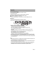
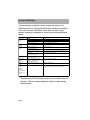
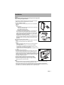
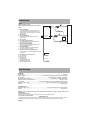
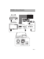
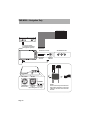
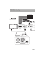
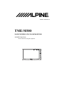
/////alpine
®
Printed in Taiwan R.O.C.
TME-M580
5.8-INCH WIDE LCD COLOR MONITOR
OWNER’S MANUAL
Please read before using this equipment.
Points to Observe for Safe Usage
WARNING
This symbol means important instructions.
Failure to heed them can result in serious injury or death.
DO NOT DISASSEMBLE OR ALTER. Doing so may result in an accident, fire or electric shock.
KEEP SMALL OBJECTS SUCH AS BATTERIES OUT OF THE REACH OF CHILDREN. Swallowing them
may result in serious injury. If swallowed, consult a physician immediately.
USE THE CORRECT AMPERE RATING WHEN REPLACING FUSES. Failure to do so may result in fire or
electric shock.
USE ONLY IN CARS WITH A 12 VOLT NEGATIVE GROUND. (Check with your dealer if you are not sure.)
Failure to do so may result in fire, etc.
BEFORE WIRING, DISCONNECT THE CABLE FROM THE NEGATIVE BATTERY TERMINAL. Failure to do
so may result in electric shock or injury due to electrical shorts.
DO NOT SPLICE INTO ELECTRICAL CABLES. Never cut away cable insulation to supply power to other
equipment. Doing so will exceed the current carrying capacity of the wire and result in fire or electric shock.
DO NOT INSTALL IN LOCATIONS WHICH MIGHT HINDER VEHICLE OPERATION, SUCH AS THE
STEERING WHEEL OR GEARSHIFT. Doing so may obstruct forward vision or hamper movement etc. and
results in serious accident.
DO NOT USE BOLTS OR NUTS IN THE BRAKE OR STEERING SYSTEMS TO MAKE GROUND
CONNECTIONS. Bolts or
nuts used for the brake or steering systems (or any other safety-related system), or tanks should NEVER be
used for installations or ground connections. Using such parts could disable control of the vehicle and cause
fire etc.
DO NOT OPERATE ANY FUNCTION THAT TAKES YOUR ATTENTION AWAY FROM SAFELY DRIVING
YOUR VEHICLE. Any function that requires your prolonged attention should only be performed after coming to
a complete stop. Always stop the vehicle in a safe location before performing these functions. Failure to do so
may result in an accident.
DO NOT ALLOW CABLES TO BECOME ENTANGLED IN SURROUNDING OBJECTS. Arrange wiring and
cables in compliance with the manual to prevent obstructions when driving. Cables or wiring that obstruct or
hang up on places such as the steering wheel, gear lever, brake pedals, etc. can be extremely hazardous.
DO NOT DAMAGE PIPE OR WIRING WHEN DRILLING HOLES. When drilling holes in the chassis for
installation, take precautions so as not to contact, damage or obstruct pipes, fuel lines, tanks or electrical
wiring. Failure to take such precautions may result in fire.
MAKE THE CORRECT CONNECTIONS. Failure to make the proper connections may result in fire or product
damage.
KEEP THE VOLUME AT A LEVEL WHERE YOU CAN STILL HEAR OUTSIDE NOISE WHILE DRIVING.
Failure to do so may result in an accident.
USE THIS PRODUCT FOR MOBILE 12V APPLICATIONS. Use for other than its designed application may
result in fire, electric shock or other injury.
DO NOT INSTALL THE MONITOR NEAR THE PASSENGER SEAT AIR BAG. If the unit is not installed
correctly the air bag may not function correctly and when triggered the air bag may cause the monitor to spring
upwards causing an accident and injuries.
MINIMIZE DISPLAY VIEWING WHILE DRIVING. Viewing the display may distract the driver from looking
ahead of the vehicle and cause an accident.
DO NOT WATCH VIDEO WHILE DRIVING. Watching the video may distract the driver from looking ahead of
the vehicle and cause an accident.
INSTALL THE PRODUCT CORRECTLY SO THAT THE DRIVER CANNOT WATCH TV/VIDEO UNLESS
THE VEHICLE IS STOPPED AND THE EMERGENCY BRAKE IS APPLIED. It is dangerous (and illegal in
many states) for the driver to watch TV/Video while driving a vehicle. Installing this product incorrectly enables
the driver to watch TV/Video while driving. This may cause a distraction, preventing the driver from looking
ahead, thus causing an accident. The driver or other people could be severely injured.
Points to Observe for Safe Usage
CAUTION
This symbol means important instructions.
Failure to heed them can result in injury or material property damage.
ARRANGE THE WIRING SO IT IS NOT CRIMPED OR PINCHED BY A SHARP METAL EDGE. Route the
cables and wiring away from moving parts (like the seat rails) or sharp or pointed edges. This will prevent
crimping and damage to the wiring. If wiring passes through a hole in metal, use a rubber grommet to prevent
the wire’s insulation from being cut by the metal edge of the hole.
USE SPECIFIED ACCESSORY PARTS AND INSTALL THEM SECURELY. Be sure to use only the specified
accessory parts. Use of other than designated parts may damage this unit internally or may not securely install
the unit in place. This may cause parts to become loose resulting in hazards or product failure.
DO NOT INSTALL IN LOCATIONS WITH HIGH MOISTURE OR DUST. Avoid installing the unit in locations
with high incidence of moisture or dust. Moisture or dust that penetrates into this unit may result in product
failure.
HAVE THE WIRING AND INSTALLATION DONE BY EXPERTS. The wiring and installation of this unit
requires special technical skill and experience. To ensure safety, always contact the dealer where you
purchased this product to have the work done.
HALT USE IMMEDIATELY IF A PROBLEM APPEARS. Failure to do so may cause personal injury or damage
to the product. Return it to your authorized Alpine dealer or the nearest Alpine Service Center for repairing.
Operation
Main power indicator
PWR
UP
DN
SEL
DISP
Remote control sensor
(The remote control is
sold separately)
NOTE: Controllable with Remote Control
This unit can be controlled with an optional Alpine remote control. For details, consult your Alpine dealer. Point
the optional remote control transmitter at the remote control sensor.
Screen Display ON/OFF
1. Press the PWR button.
2. To turn off the POWER, press the PWR button again.
Note:
If properly connected, the monitors main POWER will turn off when the vehicle’s
ignition switch is off. If the main power lamp illuminates in the STAND BY mode, the
vehicle’s battery may be discharged.
Adjusting the Volume
1. Adjust the volume level by pressing the
DN or
UP button.
Switching NTSC/PAL
Switch the movie output type NTSC/PAL in AUX mode.
1. Press the DISP button for at least 1 second.
Note: When the movie output type is not compatible, the movie does not output
normally.
Switching the source
1. Press the SEL button. Each press of the button will cycle through the modes as
follows:
AUX
NAVIGATION
Switching the display mode.
1. Press the DISP button.
Each press of the button will cycle through the modes as follows:
WIDE
CINEMA
ZOOM
NORMAL
WIDE: Normal images are expanded uniformly in the horizontal direction and are
displayed over the entire screen.
CINEMA: Normal images are expanded in the horizontal and vertical directions.
The top and bottom of the image is cut off. This mode is suited for 16:9 cinema size
images.
ZOOM: Normal images are expanded in the horizontal direction and are displayed
over the entire screen. The expansion ratio increases towards the right and left
edges of the screen.
NORMAL: Normal image (4:3)
Page 4
Operation
Reset the Monitor Settings
1. Press and hold the PWR button for at least 1 second.
2. Press the SEL button.
3. Select the Navigation system by pressing the DN or UP button.
: Standard - Navigation for all others (except Europe)
: Europe - Navigation for Europe only
If no key is pressed within 10 seconds, the On-Screen Display wil turn off.
Adjustment
1. Press and hold the SEL button for at least 1 second.
2. Each press of the button will cycle through the modes as follows:
BRIGHT
COLOR
TINT
DIMMER
MONITOR
MIRROR
DIM.
LEVEL
3. Adjust by pressing the
DN or
UP button.
• BRIGHT: Allows the brightness of the picture.
• COLOR: Change the color balance of the picture.
Note: It is not adjustable in NAVIGATION (RGB connection) mode.
• TINT: Adjust the tint of the picture.
Note: It is not adjustable in NAVIGATION (RGB connection) and PAL mode.
• DIMMER:
AUTO: Display illumination will dim when while the car’s parking lights are on.
LOW: Backlighting is set to the adjusted DIM.LEVEL.
HIGH: Backlighting is set to its maximum level.
• DIM.LEVEL: Adjust the backlighting level for LOW DIMMER.
• MIRROR: Switch the picture to NORMAL/MIRROR (for rear view camera) image.
4. After completing adjustments, press and hold the SEL button for at least 1 second.
If no key is pressed within 10 seconds, the OSD will turn off and any changes made
are automatically set.
Notes:
• After turning the system off, a slight ghost of the image will remain temporarily. This
is an effect peculiar to LCD technology and is normal.
• Under cold temperature conditions, the screen may lose contrast temporarily. After
a short warm-up period, it will return to normal.
• The LCD panel is manufactured using an extremely high precision manufacturing
technology. Its effective pixel ratio is over 99.99%. This means that there is a
possibility that 0.01% of the pixels could be either always ON or OFF.
Page 5
In Case of Difficulty
If you encounter a problem, please review the items in the
following check list. This guide will help you isolate the problem
if the unit is at fault. Otherwise, make sure the rest of your
system is properly connected or consult your authorized Alpine
dealer.
Symptom
Cause
Solution
No function or
Car's ignition is off.
Turn the ignition on.
display.
No fuse or blown fuse.
Check the cause and replace the fuse.
Incorrect connections.
Check connection and remedy.
Vehicle's battery is weak.
Check the voltage of vehicle's battery.
Fluorescent tube is exhausted.
Replace the fluorescent tube*.
No picture
Brightness control is set for
Adjust the brightness.
display.
minimum brightness control.
Unclear picture
display.
Incorrect setting of the Input mode.
Switch to the correct mode.
Protective circuit is on because of
Wait until the temperature inside the vehicle comes down to the
high temperature.
operating temperature range (45°C).
Incorrect or open connection with
Check the connection and remedy.
the Monitor, AV Interface unit.
Picture color is
Brightness/Color/Tint control are not
poor.
set to the proper positions.
Spots or dotted
Caused by neon signs, high-voltage
lines/stripes
power lines, CB transmitter, other
Check each control.
Change the location of your vehicle.
appear.
vehicle's ignition plugs, etc.
Unit does not
Monitor's power is not turned on.
Turn on the monitor's power.
Navigation
Navigation system’s power is turned
Press the ON/OFF (POWER) button on the navigation system’s
screen is not
off.
remote controller to turn the navigation system’s power on.
operate.
displayed or
navigation
system’s remote
controller keys do
not work.
* Replacement of the fluorescent tube is not covered under the
warranty. This is a consumable part subject to wear during
normal usage.
Page 6
Installation
Caution:
Do not install the monitor near the front passenger seat air bag system.
<Mount it using the supplied bracket>
1. Assemble the supplied bracket and mount the monitor temporarily.
Note: Always use the supplied bracket or equivalent.
2. Verify the installation location.
Select a flat surface and temporarily mount the unit. Use adhesive
tape, etc.
Notes:
• Mounting hints
• Top of the monitor should not exceed the top of the dash when
viewed from the driver’s seat.
• Use a stable mounting surface.
• Angle the monitor for easy viewing.
• In a vehicle with a front passenger air bag, do not install the unit
where it will interfere with the operation of the safety systems.
• If the surface of the dash board is finished with other than plastic
(leather, wooden panel, cloth covered panel, etc.), there will be
some damage if the bracket is removed.
• Installation close to other equipment (such as a GPS antenna) may
give rise to mutual interference. Please pay careful attention to the
installation location and maintain sufficient space between other
equipment.
3. Remove the monitor from the bracket.
4. Peel the protective paper from the double-stick tape on the bracket’s
base.
Clean the mounting location with a suitable cleaner.
Notes:
• Warm the mounting location with a dryer, etc. and then place the
bracket into position.
• Do not apply force or moisture for 24 hours after installation.
• If the bracket is not attached securely with just the tape, use the
supplied screws to complete the installation.
• If the mounted surface is curved slightly, reform the base to fit to its
shape.
5. Mount the monitor to the bracket.
Thread the mounting screw into hole at the bottom of the monitor.
Secure the monitor by tightening the screw. Depending upon the
location, the bracket can also be mounted using the supplied nut to
slide into the back of the monitor. Thread the bracket mounting screw
into the nut. Slide the nut in the channel on the back of the monitor
and adjust the height and tighten.
Dress the monitor’s cable using the cord clamp provided.
6. Adjust the height and angle of the monitor for easy visibility.
Determine the height and angle. Tighten the height and angle
adjusting screws to secure the monitor.
1
2
5
NOTE:
• The A/V Interface box may be mounted in any suitable location. Make sure the box and the wires
connected to it will not interfere with safely operating the vehicle.
• Mounting the Interface box near the monitor will reduce the need for additional cable extensions.
• This monitor can be mounted in a headrest if desired. A special mounting kit is required and can be
purchased from your Authorized Alpine dealer. Ask for model KTE-580V.
Page 7
Connections
Cautions
Make connections correctly.
Improper connections may cause a fire or operation
failure.
1 Ground lead (Black)
Connect the lead to a good chassis ground on the
vehicle. Make sure the connection is made to bare
metal and is securely fastened using the sheet metal
screw provided.
2 No Connection
3 ACC power lead (Red)
To ACC power lead powered when engine key
position is ACC.
4 No Connection
5 Foot brake lead (Yellow/Black)
Connect this lead to the foot brake lead powered
when the foot brake is pressed.
6 Hand brake lead (Yellow/Blue)
Connect this lead to the hand brake lead powered
when the hand brake is pulled.
7 Dimmer (White/Blue)
To the Parking Light switch. Backlighting will dim
when lights are turned on at night.
8 Remote control output lead (White/Brown)
To remote control input lead of ALPINE products used
in the system.
For the North American Customers only
p Foot brake lamp
q Brake connector
w Foot brake lead
e Foot brake switch
r Hand (parking) brake lamp
t Hand (parking) brake lead
y Hand (parking) brake switch
p
5
q
w
e
r
6
Battery
q
t
y
Chassis
8
7
3
1
Specifications
MONITOR
Screen Size ......................................................................................................................................... 5.8-type
Display System ...................................................... Low reflection rear projection type TN liquid crystal panel
Drive System .................................................................................. Active matrix drive, normally white display
Number of Picture Elements .................................................................... 280,800 pcs. (H:1200 x V:234 dots)
Effective Number of Picture Elements .................................................................................... 99.99% or more
Light Source ................................................... Internal optical system (U-type cold cathode fluorescent tube)
Dimensions (W x H x D) ........................................................... 160 x 93 x 27 mm (6.30 x 3.66 x 1.06 inches)
Weight ....................................................................................................................................... 298g (10.5 oz)
AV Interface Unit
Dimensions (W x H x D) ............................................................. 72 x 60 x 24 mm (2.84 x 2.36 x 0.95 inches)
Weight ....................................................................................................................................... 128 g (4.5 oz.)
Note: Due to continuous product improvement, specifications and design are subject to change without notice.
SERVICE CARE
• For European Customers
Should you have any questions about warranty, please consult your authorized Alpine Dealer.
• For Customers in other Countries
IMPORTANT NOTICE
Customers who purchase the product with which this notice is packaged, and who make this purchase in countries other than
the United States of America and Canada, please contact your dealer for information regarding warranty coverage.
Page 8
TME-M580 + Video and Navigation
Power Harness Color Code
3 pin EXT.PWR Cord
This cord is only used when using this
monitor as a navigation monitor only.
MIC/SW
TD DISP.
EX-1
GPS ANT.
5
1
10
6
Ground
Black
2
NOT USED
OPEN
3
4
Accessory
NOT USED
Red
OPEN
5
Foot Brake (+)
Yellow/Black
6
Parking Brake (-)
Yellow/Blue
7
8
Dimmer (+)
IR Remote
White/Blue
White/Brown
White Brown
POWER
EX-2
1
VIDEO
13 Pin Nav Cable
(included with Alpine
Navigation systems)
Ext Box Front side
8 Pin Power
Harness
TO BRAIN
Ext Box Back side
8 Pin to
Monitor
TO NAV
NOT USED
8 Pin Din to
Monitor Brain
3 Pin EXT
13 Pin Nav
(if running
Cable to
Alpine Navigation nav only)
Page 9
TME-M580 + Navigation Only
Power Harness Color Code
1
Ground
Black
2
NOT USED
OPEN
3
Accessory
Red
4
NOT USED
OPEN
5
Foot Brake (+)
Yellow/Black
6
Parking Brake (-)
Yellow/Blue
7
Dimmer (+)
IR Remote
White/Blue
White/Brown
8
MIC/SW
TD DISP.
EX-1
POWER
EX-2
GPS ANT.
5
1
10
6
13 Pin Nav Cable
(included with Alpine
Navigation systems)
Ext Box Front side
8 Pin Power
Harness
NOT USED
Ext Box Back side
8 Pin to
Monitor
TO NAV
TO BRAIN
8 Pin Din to
Monitor Brain
Page 10
3 Pin EXT
13 Pin Nav
(if running
Cable to
Alpine Navigation nav only)
NOTE:
Please use the tape included to tie
both cables together to ensure the
cable will not come loose from the
monitor.
TME-M580 + Video Only
Power Harness Color Code
1
Ground
2
NOT USED
OPEN
3
4
Accessory
NOT USED
Red
OPEN
Black
5
Foot Brake (+)
6
Parking Brake (-)
Yellow/Blue
7
8
Dimmer (+)
IR Remote
White/Blue
White/Brown
Yellow/Black
3 pin EXT.PWR Cord
White Brown
This cord is only used when using this
monitor as a navigation monitor only.
VIDEO
EXT Box Front side
8 Pin Power
Harness
TO BRAIN
EXT Box Back side
8 Pin to
Monitor
NOT USED
NOT USED
8 Pin Din to
Monitor Brain
3 Pin EXT
13 Pin Nav
(if running
Cable to
Alpine Navigation nav only)
Page 11
/////alpine
®
ALPINE ELECTRONICS, INC.
Tokyo office: 1-1-8 Nishi Gotanda,
Shinagawa-ku, Tokyo 141-8501, Japan
Tel.: (03) 3494-1101
ALPINE ITALIA S.p.A.
Viale C. Colombo 8,
20090 Trezzano Sul Naviglio (MI), Italy
Tel.: 02-48 47 81
ALPINE ELECTRONICS OF AMERICA, INC.
19145 Gramercy Place, Torrance,
California 90501, U.S.A.
Tel.:1-800-ALPINE-1 (1-800-257-4631)
ALPINE ELECTRONICS FRANCE
S.A.R.L.
(RCS PONTOISE B 338 101 280)
98, Rue de la Belle Etoile, Z.I. Paris
Nord II, B.P. 50016, 95945, Roissy
Charles de Gaulle Cedex, France
Tel.: 01-48 63 89 89
ALPINE ELECTRONICS OF CANADA, INC.
7300 Warden Ave., Suite 203, Markham,
Ontario L3R 9Z6, Canada
Tel.:1-800-ALPINE-1 (1-800-257-4631)
ALPINE ELECTRONICS OF U. K., LTD.
13 Tanners Drive, Blakelands,
Milton Keynes MK14 5BU, U.K.
Tel.: 01908-61 15 56
ALPINE ELECTRONICS OF AUSTRALIA PTY. LTD.
6-8 Fiveways Boulevarde Keysborough,
Victoria 3173, Australia
Tel.: (03) 9769-0000
ALPINE ELECTRONICS DE ESPAÑA,
S.A.
Portal de Gamarra 36, Pabellón, 32
01013 Vitoria (Alava) - APDO 133,
Spain
Tel.: 945-283588
ALPINE ELECTRONICS GmbH
Kreuzerkamp 7, 40878 Ratingen,
Germany
Tel.: 02102-45 50