1
User's Guide
REFERENCE
86 A1 41EM 06
NOVASCALE
NovaScale 5xx5
BLANK
NOVASCALE
NovaScale 5xx5
User's Guide
Hardware
September 2007
BULL CEDOC
357 AVENUE PATTON
B.P.20845
49008 ANGERS CEDEX 01
FRANCE
REFERENCE
86 A1 41EM 06
The following copyright notice protects this book under Copyright laws which prohibit such actions as, but not
limited to, copying, distributing, modifying, and making derivative works.
Copyright
Bull SAS 1992, 2007
Printed in France
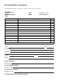
Suggestions and criticisms concerning the form, content, and presentation of this
book are invited. A form is provided at the end of this book for this purpose.
To order additional copies of this book or other Bull Technical Publications, you
are invited to use the Ordering Form also provided at the end of this book.
Trademarks and Acknowledgements
We acknowledge the right of proprietors of trademarks mentioned in this book.
Intel
and Itanium
Windows
are registered trademarks of Intel Corporation.
and Microsoft software
are registered trademarks of Microsoft Corporation.
UNIX is a registered trademark in the United States of America and other countries licensed exclusively through
the Open Group.
Linux
is a registered trademark of Linus Torvalds.
The information in this document is subject to change without notice. Bull will not be liable for errors contained
herein, or for incidental or consequential damages in connection with the use of this material.
Preface
Table of Contents
Intended Readers . . . . . . . . . . . . . . . . . . . . . . . . . . . . . . . . . . . . . . . . . . . . . . . . . . . . . . . . .
Highlighting . . . . . . . . . . . . . . . . . . . . . . . . . . . . . . . . . . . . . . . . . . . . . . . . . . . . . . . . . . . . .
Related Publications . . . . . . . . . . . . . . . . . . . . . . . . . . . . . . . . . . . . . . . . . . . . . . . . . . . . . .
Regulatory Specifications and Disclaimers . . . . . . . . . . . . . . . . . . . . . . . . . . . . . . . . . . .
Declaration of the Manufacturer or Importer . . . . . . . . . . . . . . . . . . . . . . . . . . . . . . .
Safety Compliance Statement . . . . . . . . . . . . . . . . . . . . . . . . . . . . . . . . . . . . . . . . . . . .
European Community (EC) Council Directives . . . . . . . . . . . . . . . . . . . . . . . . . . . . . .
Federal Communications Commission (FCC) Statement . . . . . . . . . . . . . . . . . . . . . .
FCC Declaration of Conformity . . . . . . . . . . . . . . . . . . . . . . . . . . . . . . . . . . . . . . . . . .
Canadian Compliance Statement (Industry Canada) . . . . . . . . . . . . . . . . . . . . . . . .
Laser Compliance Notice . . . . . . . . . . . . . . . . . . . . . . . . . . . . . . . . . . . . . . . . . . . . . . .
Definition of Safety Notices . . . . . . . . . . . . . . . . . . . . . . . . . . . . . . . . . . . . . . . . . . . . . . . .
Electrical Safety . . . . . . . . . . . . . . . . . . . . . . . . . . . . . . . . . . . . . . . . . . . . . . . . . . . . . . . . . .
Laser Safety Information . . . . . . . . . . . . . . . . . . . . . . . . . . . . . . . . . . . . . . . . . . . . . . . . . . .
Data Integrity and Verification . . . . . . . . . . . . . . . . . . . . . . . . . . . . . . . . . . . . . . . . . . . . . .
Waste Management . . . . . . . . . . . . . . . . . . . . . . . . . . . . . . . . . . . . . . . . . . . . . . . . . . . . . .
PAM Writing Rules . . . . . . . . . . . . . . . . . . . . . . . . . . . . . . . . . . . . . . . . . . . . . . . . . . . . . . .
Illegal Characters . . . . . . . . . . . . . . . . . . . . . . . . . . . . . . . . . . . . . . . . . . . . . . . . . . . . . .
String Lengths . . . . . . . . . . . . . . . . . . . . . . . . . . . . . . . . . . . . . . . . . . . . . . . . . . . . . . . . .
Registry Keys . . . . . . . . . . . . . . . . . . . . . . . . . . . . . . . . . . . . . . . . . . . . . . . . . . . . . . . . . .
AZERTY/QWERTY Keyboard Lookup Table . . . . . . . . . . . . . . . . . . . . . . . . . . . . . . . . . .
Administrator's Memorandum . . . . . . . . . . . . . . . . . . . . . . . . . . . . . . . . . . . . . . . . . . . . . .
Operator's Memorandum . . . . . . . . . . . . . . . . . . . . . . . . . . . . . . . . . . . . . . . . . . . . . . . . . .
xvii
xvii
xvii
xviii
xviii
xviii
xviii
xix
xix
xix
xix
xx
xx
xxi
xxi
xxi
xxii
xxii
xxiii
xxiii
xxiv
xxv
xxvii
Chapter 1. Introducing the Server . . . . . . . . . . . . . . . . . . . . . . . . . . . . . . . . . . . . . . . . . .
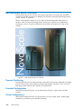
Bull Novascale Server Overview . . . . . . . . . . . . . . . . . . . . . . . . . . . . . . . . . . . . . . . . . . .
Dynamic Partitioning . . . . . . . . . . . . . . . . . . . . . . . . . . . . . . . . . . . . . . . . . . . . . . . . . . .
Extended Configurations . . . . . . . . . . . . . . . . . . . . . . . . . . . . . . . . . . . . . . . . . . . . . . . .
Cluster Configurations . . . . . . . . . . . . . . . . . . . . . . . . . . . . . . . . . . . . . . . . . . . . . . . . . .
Server Features . . . . . . . . . . . . . . . . . . . . . . . . . . . . . . . . . . . . . . . . . . . . . . . . . . . . . . . .
Server Hardware . . . . . . . . . . . . . . . . . . . . . . . . . . . . . . . . . . . . . . . . . . . . . . . . . . . . . .
Central SubSystem Module (CSS Module) . . . . . . . . . . . . . . . . . . . . . . . . . . . . . . .
Front Unit . . . . . . . . . . . . . . . . . . . . . . . . . . . . . . . . . . . . . . . . . . . . . . . . . . . . . . . . . .
Core Unit . . . . . . . . . . . . . . . . . . . . . . . . . . . . . . . . . . . . . . . . . . . . . . . . . . . . . . . . . .
Rear Unit . . . . . . . . . . . . . . . . . . . . . . . . . . . . . . . . . . . . . . . . . . . . . . . . . . . . . . . . . . .
Platform Administration Processor (PAP) Unit . . . . . . . . . . . . . . . . . . . . . . . . . . . . .
KVM Switch . . . . . . . . . . . . . . . . . . . . . . . . . . . . . . . . . . . . . . . . . . . . . . . . . . . . . . . .
Console . . . . . . . . . . . . . . . . . . . . . . . . . . . . . . . . . . . . . . . . . . . . . . . . . . . . . . . . . . . .
Disk Subsystem . . . . . . . . . . . . . . . . . . . . . . . . . . . . . . . . . . . . . . . . . . . . . . . . . . . . . .
Additional Peripherals . . . . . . . . . . . . . . . . . . . . . . . . . . . . . . . . . . . . . . . . . . . . . . . .
Server Firmware and Software . . . . . . . . . . . . . . . . . . . . . . . . . . . . . . . . . . . . . . . . . . .
Conformance to Standards . . . . . . . . . . . . . . . . . . . . . . . . . . . . . . . . . . . . . . . . . . . . . .
Getting to Know the Server . . . . . . . . . . . . . . . . . . . . . . . . . . . . . . . . . . . . . . . . . . . . . . . .
NovaScale 5085 Partitioned Server . . . . . . . . . . . . . . . . . . . . . . . . . . . . . . . . . . . . . .
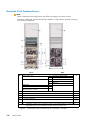
NovaScale 5165 Partitioned Server . . . . . . . . . . . . . . . . . . . . . . . . . . . . . . . . . . . . . .
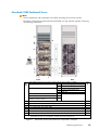
NovaScale 5245 Partitioned Server . . . . . . . . . . . . . . . . . . . . . . . . . . . . . . . . . . . . . .
1-1
1-2
1-2
1-2
1-2
1-3
1-4
1-4
1-4
1-4
1-5
1-5
1-5
1-5
1-5
1-5
1-5
1-6
1-7
1-7
1-8
1-9
Preface
iii
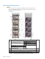
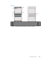
NovaScale 5325 Partitioned Server . . . . . . . . . . . . . . . . . . . . . . . . . . . . . . . . . . . . . .
Server Components . . . . . . . . . . . . . . . . . . . . . . . . . . . . . . . . . . . . . . . . . . . . . . . . . . . . . . .
Central Subsystem (CSS) Module . . . . . . . . . . . . . . . . . . . . . . . . . . . . . . . . . . . . . . . . .
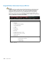
Integrated Platform Administration Processor (PAP) Unit . . . . . . . . . . . . . . . . . . . . . .
Integrated Console . . . . . . . . . . . . . . . . . . . . . . . . . . . . . . . . . . . . . . . . . . . . . . . . . . . . .
Keyboard / Video / Mouse (KVM) Switch . . . . . . . . . . . . . . . . . . . . . . . . . . . . . . . .
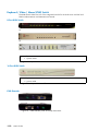
8-Port KVM Switch . . . . . . . . . . . . . . . . . . . . . . . . . . . . . . . . . . . . . . . . . . . . . . . . . . .
16-Port KVM Switch . . . . . . . . . . . . . . . . . . . . . . . . . . . . . . . . . . . . . . . . . . . . . . . . .
KVM Extender . . . . . . . . . . . . . . . . . . . . . . . . . . . . . . . . . . . . . . . . . . . . . . . . . . . . . .
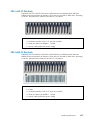
FDA 1x00 FC Disk Rack . . . . . . . . . . . . . . . . . . . . . . . . . . . . . . . . . . . . . . . . . . . . . . . .
FDA 2x00 FC Disk Rack . . . . . . . . . . . . . . . . . . . . . . . . . . . . . . . . . . . . . . . . . . . . . . . .
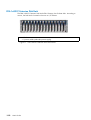
FDA 1x00 FC Extension Disk Rack . . . . . . . . . . . . . . . . . . . . . . . . . . . . . . . . . . . . . . .
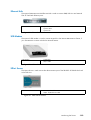
Ethernet Hub . . . . . . . . . . . . . . . . . . . . . . . . . . . . . . . . . . . . . . . . . . . . . . . . . . . . . . . . . .
USB Modem . . . . . . . . . . . . . . . . . . . . . . . . . . . . . . . . . . . . . . . . . . . . . . . . . . . . . . . . . .
NPort Server . . . . . . . . . . . . . . . . . . . . . . . . . . . . . . . . . . . . . . . . . . . . . . . . . . . . . . . . . .
Accessing Server Components . . . . . . . . . . . . . . . . . . . . . . . . . . . . . . . . . . . . . . . . . . . . .
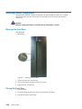
Opening the Front Door . . . . . . . . . . . . . . . . . . . . . . . . . . . . . . . . . . . . . . . . . . . . . . . .
Closing the Front Door . . . . . . . . . . . . . . . . . . . . . . . . . . . . . . . . . . . . . . . . . . . . . . . . . .
Opening / Closing the Integrated Console . . . . . . . . . . . . . . . . . . . . . . . . . . . . . . . .
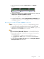
Bull NovaScale Server Resources . . . . . . . . . . . . . . . . . . . . . . . . . . . . . . . . . . . . . . . . . . .
System Resource and Documentation CD-Roms . . . . . . . . . . . . . . . . . . . . . . . . . . . . .
PAM Software Package . . . . . . . . . . . . . . . . . . . . . . . . . . . . . . . . . . . . . . . . . . . . . . . . .
PAP Unit Mirroring and Failover Policy . . . . . . . . . . . . . . . . . . . . . . . . . . . . . . . . .
EFI Utilities . . . . . . . . . . . . . . . . . . . . . . . . . . . . . . . . . . . . . . . . . . . . . . . . . . . . . . . . . . . .
1-10
1-12
1-13
1-14
1-15
1-16
1-16
1-16
1-16
1-17
1-17
1-18
1-19
1-19
1-19
1-20
1-20
1-20
1-21
1-22
1-22
1-22
1-22
1-23
Chapter 2. Getting Started . . . . . . . . . . . . . . . . . . . . . . . . . . . . . . . . . . . . . . . . . . . . . . . . .
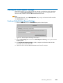
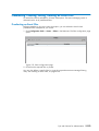
Connecting to the PAM Web Site . . . . . . . . . . . . . . . . . . . . . . . . . . . . . . . . . . . . . . . . . . .
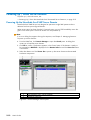
Connecting to the PAM Web Site from the Local / Integrated Console . . . . . . . . .
Connecting to the PAM Web Site from a Remote Computer . . . . . . . . . . . . . . . . . .
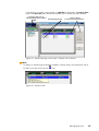
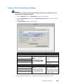
Enabling Remote Access to the PAM Web Site with Internet Explorer,
Mozilla, or Firefox . . . . . . . . . . . . . . . . . . . . . . . . . . . . . . . . . . . . . . . . . . . . . . . . . . .
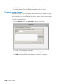
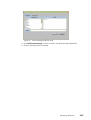
Simultaneous Connection to the PAM Web Site . . . . . . . . . . . . . . . . . . . . . . . . . . . .
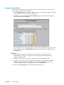
PAM User Interface . . . . . . . . . . . . . . . . . . . . . . . . . . . . . . . . . . . . . . . . . . . . . . . . . . . . . . .
Checking Server Status via PAM . . . . . . . . . . . . . . . . . . . . . . . . . . . . . . . . . . . . . . . . . . . .
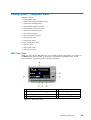
PAM Status Pane . . . . . . . . . . . . . . . . . . . . . . . . . . . . . . . . . . . . . . . . . . . . . . . . . . . . . . .
PAM Control Pane . . . . . . . . . . . . . . . . . . . . . . . . . . . . . . . . . . . . . . . . . . . . . . . . . . . . .
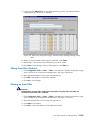
CSS Availability Status Bar . . . . . . . . . . . . . . . . . . . . . . . . . . . . . . . . . . . . . . . . . . . . . .
PAM Tree Pane . . . . . . . . . . . . . . . . . . . . . . . . . . . . . . . . . . . . . . . . . . . . . . . . . . . . . . . .
Setting up Users . . . . . . . . . . . . . . . . . . . . . . . . . . . . . . . . . . . . . . . . . . . . . . . . . . . . . . .
Toggling the Local / Integrated Console Display . . . . . . . . . . . . . . . . . . . . . . . . . . . . . .
Powering Up / Down Server Domains . . . . . . . . . . . . . . . . . . . . . . . . . . . . . . . . . . . . . .
Powering Up the NovaScale 5xx5 SMP Server Domain . . . . . . . . . . . . . . . . . . . . .
Powering Down the NovaScale 5xx5 SMP Server Domain . . . . . . . . . . . . . . . . . . .
Powering Up NovaScale 5xx5 Partitioned Server Domains . . . . . . . . . . . . . . . . . .
Powering Down NovaScale 5xx5 Partitioned Server Domains . . . . . . . . . . . . . . . .
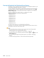
Preparing Server Domains for Remote Access via the Enterprise LAN . . . . . . . . . . . .
Microsoft Windows Domain . . . . . . . . . . . . . . . . . . . . . . . . . . . . . . . . . . . . . . . . . . . . .
Linux Redhat Domain . . . . . . . . . . . . . . . . . . . . . . . . . . . . . . . . . . . . . . . . . . . . . . . . . . .
Linux SuSE Domain . . . . . . . . . . . . . . . . . . . . . . . . . . . . . . . . . . . . . . . . . . . . . . . . . . . .
Preparing Server Domains for Remote Access via the Web . . . . . . . . . . . . . . . . . . . . .
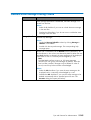
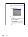
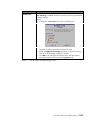
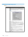
Microsoft Windows Domain . . . . . . . . . . . . . . . . . . . . . . . . . . . . . . . . . . . . . . . . . . . . .
Linux Domain . . . . . . . . . . . . . . . . . . . . . . . . . . . . . . . . . . . . . . . . . . . . . . . . . . . . . . . . .
Connecting to a Server Domain via the Enterprise LAN . . . . . . . . . . . . . . . . . . . . . . . .
Microsoft Windows Domain . . . . . . . . . . . . . . . . . . . . . . . . . . . . . . . . . . . . . . . . . . . . .
Linux Domain . . . . . . . . . . . . . . . . . . . . . . . . . . . . . . . . . . . . . . . . . . . . . . . . . . . . . . . . .
2-1
2-2
2-2
2-3
iv User's Guide
2-3
2-4
2-5
2-6
2-6
2-6
2-7
2-7
2-8
2-9
2-10
2-10
2-11
2-12
2-15
2-16
2-16
2-16
2-17
2-18
2-18
2-18
2-19
2-19
2-19
Connecting to the Server via the Web . . . . . . . . . . . . . . . . . . . . . . . . . . . . . . . . . . . . . . .
Microsoft Windows Domain . . . . . . . . . . . . . . . . . . . . . . . . . . . . . . . . . . . . . . . . . . . . .
Linux Domain . . . . . . . . . . . . . . . . . . . . . . . . . . . . . . . . . . . . . . . . . . . . . . . . . . . . . . . . .
Installing Applications . . . . . . . . . . . . . . . . . . . . . . . . . . . . . . . . . . . . . . . . . . . . . . . . . . . . .
2-20
2-20
2-20
2-21
Chapter 3. Managing Domains . . . . . . . . . . . . . . . . . . . . . . . . . . . . . . . . . . . . . . . . . . . . .
Introducing PAM Domain Management Tools . . . . . . . . . . . . . . . . . . . . . . . . . . . . . . . . .
Managing Domain Configuration Schemes . . . . . . . . . . . . . . . . . . . . . . . . . . . . . . . . . .
Synchronizing NovaScale 5xx5 SMP Server Domains . . . . . . . . . . . . . . . . . . . . . .
Viewing a Domain Configuration Scheme . . . . . . . . . . . . . . . . . . . . . . . . . . . . . . . . .
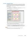
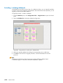
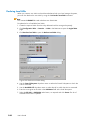
Loading a Domain Configuration Scheme . . . . . . . . . . . . . . . . . . . . . . . . . . . . . . . . .
Adding Domains to the Current Domain Configuration . . . . . . . . . . . . . . . . . . . . . .
Replacing the Current Domain Configuration . . . . . . . . . . . . . . . . . . . . . . . . . . . . . .
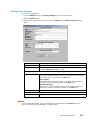
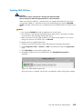
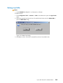
Saving the Current Domain Configuration Snapshot . . . . . . . . . . . . . . . . . . . . . . . .
Powering On a Domain . . . . . . . . . . . . . . . . . . . . . . . . . . . . . . . . . . . . . . . . . . . . . . . . . . .
Powering On a Single Domain . . . . . . . . . . . . . . . . . . . . . . . . . . . . . . . . . . . . . . . . . .
Powering On Multiple Domains . . . . . . . . . . . . . . . . . . . . . . . . . . . . . . . . . . . . . . . . . .
Powering Off a Domain . . . . . . . . . . . . . . . . . . . . . . . . . . . . . . . . . . . . . . . . . . . . . . . . . . .
Powering Off a Single Domain . . . . . . . . . . . . . . . . . . . . . . . . . . . . . . . . . . . . . . . . . .
Powering Off Multiple Domains . . . . . . . . . . . . . . . . . . . . . . . . . . . . . . . . . . . . . . . . . .
Forcing a Domain Power Off . . . . . . . . . . . . . . . . . . . . . . . . . . . . . . . . . . . . . . . . . . . . . .
Forcibly Powering Off a Single Domain . . . . . . . . . . . . . . . . . . . . . . . . . . . . . . . . . . .
Forcibly Powering Off Multiple Domains . . . . . . . . . . . . . . . . . . . . . . . . . . . . . . . . . .
Performing a Domain Memory Dump . . . . . . . . . . . . . . . . . . . . . . . . . . . . . . . . . . . . . . .
Manually Resetting a Domain . . . . . . . . . . . . . . . . . . . . . . . . . . . . . . . . . . . . . . . . . . . . . .
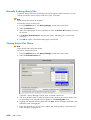
Deleting a Domain . . . . . . . . . . . . . . . . . . . . . . . . . . . . . . . . . . . . . . . . . . . . . . . . . . . . . . .
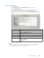
Viewing a Domain Fault List . . . . . . . . . . . . . . . . . . . . . . . . . . . . . . . . . . . . . . . . . . . . . . .
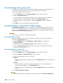
Viewing Domain Functional Status . . . . . . . . . . . . . . . . . . . . . . . . . . . . . . . . . . . . . . . . . .
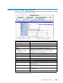
Viewing Domain Power Logs . . . . . . . . . . . . . . . . . . . . . . . . . . . . . . . . . . . . . . . . . . . . . . .
Viewing Domain Powering Sequences . . . . . . . . . . . . . . . . . . . . . . . . . . . . . . . . . . . . . . .
Viewing Domain BIOS Info . . . . . . . . . . . . . . . . . . . . . . . . . . . . . . . . . . . . . . . . . . . . . . . .
Viewing Domain Request Logs . . . . . . . . . . . . . . . . . . . . . . . . . . . . . . . . . . . . . . . . . . . . .
Viewing Domain Configuration, Resources and Status . . . . . . . . . . . . . . . . . . . . . . . . .
Viewing Domain Configuration . . . . . . . . . . . . . . . . . . . . . . . . . . . . . . . . . . . . . . . . . .
Viewing Domain Hardware Resources . . . . . . . . . . . . . . . . . . . . . . . . . . . . . . . . . . . .
Viewing Domain Details and Status . . . . . . . . . . . . . . . . . . . . . . . . . . . . . . . . . . . . . . .
What To Do if an Incident Occurs . . . . . . . . . . . . . . . . . . . . . . . . . . . . . . . . . . . . . . . . . .
Dealing with Incidents . . . . . . . . . . . . . . . . . . . . . . . . . . . . . . . . . . . . . . . . . . . . . . . . . .
3-1
3-2
3-5
3-6
3-6
3-8
3-10
3-10
3-11
3-14
3-14
3-15
3-18
3-18
3-19
3-21
3-22
3-22
3-24
3-25
3-26
3-28
3-29
3-31
3-32
3-33
3-34
3-35
3-35
3-38
3-38
3-42
3-43
Chapter 4. Monitoring the Server . . . . . . . . . . . . . . . . . . . . . . . . . . . . . . . . . . . . . . . . . . .
Introducing PAM Monitoring Tools . . . . . . . . . . . . . . . . . . . . . . . . . . . . . . . . . . . . . . . . . .
Viewing System / Component Status . . . . . . . . . . . . . . . . . . . . . . . . . . . . . . . . . . . . . . . .
PAM Status Pane . . . . . . . . . . . . . . . . . . . . . . . . . . . . . . . . . . . . . . . . . . . . . . . . . . . . . . .
CSS Availability Status . . . . . . . . . . . . . . . . . . . . . . . . . . . . . . . . . . . . . . . . . . . . . . .
System Functional Status . . . . . . . . . . . . . . . . . . . . . . . . . . . . . . . . . . . . . . . . . . . . . .
Event Message Status . . . . . . . . . . . . . . . . . . . . . . . . . . . . . . . . . . . . . . . . . . . . . . . .
PAM Tree Pane . . . . . . . . . . . . . . . . . . . . . . . . . . . . . . . . . . . . . . . . . . . . . . . . . . . . . . . .
Displaying Presence Status . . . . . . . . . . . . . . . . . . . . . . . . . . . . . . . . . . . . . . . . . . . .
Displaying Functional Status . . . . . . . . . . . . . . . . . . . . . . . . . . . . . . . . . . . . . . . . . .
Using PAM Utilities . . . . . . . . . . . . . . . . . . . . . . . . . . . . . . . . . . . . . . . . . . . . . . . . . . . . . . .
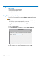
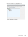
Using the Hardware Search Engine . . . . . . . . . . . . . . . . . . . . . . . . . . . . . . . . . . . . . .
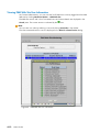
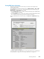
Viewing PAM Web Site User Information . . . . . . . . . . . . . . . . . . . . . . . . . . . . . . . . . .
Viewing PAM Version Information . . . . . . . . . . . . . . . . . . . . . . . . . . . . . . . . . . . . . . . .
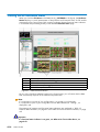
Viewing Server Hardware Status . . . . . . . . . . . . . . . . . . . . . . . . . . . . . . . . . . . . . . . . . . .
4-1
4-2
4-3
4-3
4-4
4-4
4-4
4-5
4-5
4-7
4-10
4-10
4-12
4-13
4-14
Preface
v
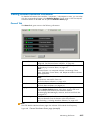
Viewing Detailed Hardware Information . . . . . . . . . . . . . . . . . . . . . . . . . . . . . . . . . . . . .
General Tab . . . . . . . . . . . . . . . . . . . . . . . . . . . . . . . . . . . . . . . . . . . . . . . . . . . . . . . . . .
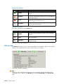
FRU Info Tab . . . . . . . . . . . . . . . . . . . . . . . . . . . . . . . . . . . . . . . . . . . . . . . . . . . . . . . . . .
Firmware Tab (Core MFL & PMB only) . . . . . . . . . . . . . . . . . . . . . . . . . . . . . . . . . . . .
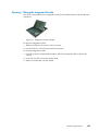
Thermal Zones (CSS module only) . . . . . . . . . . . . . . . . . . . . . . . . . . . . . . . . . . . . . . . .
Power Tab . . . . . . . . . . . . . . . . . . . . . . . . . . . . . . . . . . . . . . . . . . . . . . . . . . . . . . . . . . . .
CSS Module Power Tab . . . . . . . . . . . . . . . . . . . . . . . . . . . . . . . . . . . . . . . . . . . . . . . . .
Temperature Tab . . . . . . . . . . . . . . . . . . . . . . . . . . . . . . . . . . . . . . . . . . . . . . . . . . . . . . .
Fan Status (Fanboxes only) . . . . . . . . . . . . . . . . . . . . . . . . . . . . . . . . . . . . . . . . . . . . . .
Jumper Status (IOC only) . . . . . . . . . . . . . . . . . . . . . . . . . . . . . . . . . . . . . . . . . . . . . . . .
PCI Slots (IOC only) . . . . . . . . . . . . . . . . . . . . . . . . . . . . . . . . . . . . . . . . . . . . . . . . . . . .
Excluding / Including Hardware Elements . . . . . . . . . . . . . . . . . . . . . . . . . . . . . . . . . . .
Excluding a Hardware Element . . . . . . . . . . . . . . . . . . . . . . . . . . . . . . . . . . . . . . . . . .
Including a Hardware Element . . . . . . . . . . . . . . . . . . . . . . . . . . . . . . . . . . . . . . . . . . .
Excluding / Including Clocks, SPS, XSP Cables and Sidebands . . . . . . . . . . . . . . . . .
Excluding / Including Clocks . . . . . . . . . . . . . . . . . . . . . . . . . . . . . . . . . . . . . . . . . . . .
Excluding / Including SPS . . . . . . . . . . . . . . . . . . . . . . . . . . . . . . . . . . . . . . . . . . . . . . .
Excluding / Including XSP Cables . . . . . . . . . . . . . . . . . . . . . . . . . . . . . . . . . . . . . . . .
Excluding / Including Sidebands . . . . . . . . . . . . . . . . . . . . . . . . . . . . . . . . . . . . . . . . .
Managing PAM Messages, Histories, Archives and Fault Lists . . . . . . . . . . . . . . . . . .
Understanding PAM Message Severity Levels . . . . . . . . . . . . . . . . . . . . . . . . . . . . . .
Viewing PAM Messages and Fault Lists . . . . . . . . . . . . . . . . . . . . . . . . . . . . . . . . . . . . . .
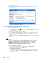
Viewing and Acknowledging PAM Web Event Messages . . . . . . . . . . . . . . . . . . . .
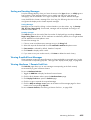
Sorting and Locating Messages . . . . . . . . . . . . . . . . . . . . . . . . . . . . . . . . . . . . . . . . . .
Viewing E-mailed Event Messages . . . . . . . . . . . . . . . . . . . . . . . . . . . . . . . . . . . . . . . .
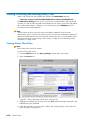
Viewing Hardware / Domain Fault Lists . . . . . . . . . . . . . . . . . . . . . . . . . . . . . . . . . . .
Viewing, Archiving and Deleting History Files . . . . . . . . . . . . . . . . . . . . . . . . . . . . . . . .
Viewing History Files Online . . . . . . . . . . . . . . . . . . . . . . . . . . . . . . . . . . . . . . . . . . . .
Viewing History Properties . . . . . . . . . . . . . . . . . . . . . . . . . . . . . . . . . . . . . . . . . . . .
Manually Archiving History Files . . . . . . . . . . . . . . . . . . . . . . . . . . . . . . . . . . . . . . . . .
Viewing Archive Files Online . . . . . . . . . . . . . . . . . . . . . . . . . . . . . . . . . . . . . . . . . . . .
Viewing Archive Properties . . . . . . . . . . . . . . . . . . . . . . . . . . . . . . . . . . . . . . . . . . .
Manually Deleting a History Archive File . . . . . . . . . . . . . . . . . . . . . . . . . . . . . . . . . .
Downloading History / Archive Files for Offline Viewing . . . . . . . . . . . . . . . . . . . .
Downloading History Viewer . . . . . . . . . . . . . . . . . . . . . . . . . . . . . . . . . . . . . . . . . .
Downloading History / Archive Files . . . . . . . . . . . . . . . . . . . . . . . . . . . . . . . . . . .
Viewing History / Archive Files Offline . . . . . . . . . . . . . . . . . . . . . . . . . . . . . . . . .
What to Do if an Incident Occurs . . . . . . . . . . . . . . . . . . . . . . . . . . . . . . . . . . . . . . . . . .
Investigating Incidents . . . . . . . . . . . . . . . . . . . . . . . . . . . . . . . . . . . . . . . . . . . . . . . . . .
Dealing with Incidents . . . . . . . . . . . . . . . . . . . . . . . . . . . . . . . . . . . . . . . . . . . . . . . . . . . .
Checking Environmental Conditions . . . . . . . . . . . . . . . . . . . . . . . . . . . . . . . . . . . . . .
Checking Hardware Availability . . . . . . . . . . . . . . . . . . . . . . . . . . . . . . . . . . . . . . . . .
Checking Hardware Connections . . . . . . . . . . . . . . . . . . . . . . . . . . . . . . . . . . . . . . . .
Excluding a Hardware Element and Checking Exclusion Status . . . . . . . . . . . . . . .
Checking Hardware Fault Status . . . . . . . . . . . . . . . . . . . . . . . . . . . . . . . . . . . . . . . . .
Checking Hardware Power Status . . . . . . . . . . . . . . . . . . . . . . . . . . . . . . . . . . . . . . . .
Checking Hardware Temperature Status . . . . . . . . . . . . . . . . . . . . . . . . . . . . . . . . . . .
Checking Histories and Events . . . . . . . . . . . . . . . . . . . . . . . . . . . . . . . . . . . . . . . . . . .
Checking SNMP Settings . . . . . . . . . . . . . . . . . . . . . . . . . . . . . . . . . . . . . . . . . . . . . . .
Checking Autocall Settings . . . . . . . . . . . . . . . . . . . . . . . . . . . . . . . . . . . . . . . . . . . . . .
Checking PAM Version . . . . . . . . . . . . . . . . . . . . . . . . . . . . . . . . . . . . . . . . . . . . . . . . .
Checking MAESTRO Version . . . . . . . . . . . . . . . . . . . . . . . . . . . . . . . . . . . . . . . . . . . .
Checking Writing Rules . . . . . . . . . . . . . . . . . . . . . . . . . . . . . . . . . . . . . . . . . . . . . . . . .
Powering OFF/ON a Domain . . . . . . . . . . . . . . . . . . . . . . . . . . . . . . . . . . . . . . . . . . .
Rebooting the PAP Application . . . . . . . . . . . . . . . . . . . . . . . . . . . . . . . . . . . . . . . . . . .
vi User's Guide
4-15
4-15
4-16
4-17
4-17
4-18
4-19
4-20
4-21
4-21
4-22
4-23
4-23
4-24
4-27
4-27
4-28
4-29
4-30
4-31
4-32
4-33
4-34
4-35
4-35
4-35
4-36
4-36
4-37
4-38
4-38
4-39
4-40
4-40
4-40
4-40
4-41
4-42
4-42
4-46
4-46
4-46
4-47
4-47
4-47
4-47
4-47
4-47
4-48
4-48
4-48
4-48
4-48
4-48
4-48
Modifying LUN Properties . . . . . . . . . . . . . . . . . . . . . . . . . . . . . . . . . . . . . . . . . . . . . . .
Checking, Testing and Resetting the PMB . . . . . . . . . . . . . . . . . . . . . . . . . . . . . . . . . .
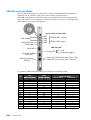
PMB LEDs and Code Wheels . . . . . . . . . . . . . . . . . . . . . . . . . . . . . . . . . . . . . . . . . . . .
Creating an Action Request Package . . . . . . . . . . . . . . . . . . . . . . . . . . . . . . . . . . . . . . . .
Creating a Default Action Request Package . . . . . . . . . . . . . . . . . . . . . . . . . . . . . . . .
Creating a Filtered Action Request Package . . . . . . . . . . . . . . . . . . . . . . . . . . . . . . .
Creating a Custom Package . . . . . . . . . . . . . . . . . . . . . . . . . . . . . . . . . . . . . . . . . . . . .
4-49
4-49
4-50
4-51
4-51
4-53
4-54
Chapter 5. Tips and Features for Administrators . . . . . . . . . . . . . . . . . . . . . . . . . . . . . .
Setting up Server Users . . . . . . . . . . . . . . . . . . . . . . . . . . . . . . . . . . . . . . . . . . . . . . . . . . .
Configuring System and Data Disks . . . . . . . . . . . . . . . . . . . . . . . . . . . . . . . . . . . . . . . . .
Creating New FC Logical System or Data Disks . . . . . . . . . . . . . . . . . . . . . . . . . . . .
Using the EFI Boot Manager . . . . . . . . . . . . . . . . . . . . . . . . . . . . . . . . . . . . . . . . . . . . . . .
EFI Boot Manager Options . . . . . . . . . . . . . . . . . . . . . . . . . . . . . . . . . . . . . . . . . . . . . .
Using the EFI Shell . . . . . . . . . . . . . . . . . . . . . . . . . . . . . . . . . . . . . . . . . . . . . . . . . . . . . . . .
Entering the EFI Shell . . . . . . . . . . . . . . . . . . . . . . . . . . . . . . . . . . . . . . . . . . . . . . . . . . .
EFI Shell Command Syntax . . . . . . . . . . . . . . . . . . . . . . . . . . . . . . . . . . . . . . . . . . . . . .
Variable Substitution . . . . . . . . . . . . . . . . . . . . . . . . . . . . . . . . . . . . . . . . . . . . . . . . .
Wildcard Expansion . . . . . . . . . . . . . . . . . . . . . . . . . . . . . . . . . . . . . . . . . . . . . . . . .
Output Redirection . . . . . . . . . . . . . . . . . . . . . . . . . . . . . . . . . . . . . . . . . . . . . . . . . . .
Quoting . . . . . . . . . . . . . . . . . . . . . . . . . . . . . . . . . . . . . . . . . . . . . . . . . . . . . . . . . . . .
Executing Batch Scripts . . . . . . . . . . . . . . . . . . . . . . . . . . . . . . . . . . . . . . . . . . . . . . . . .
Error Handling in Batch Scripts . . . . . . . . . . . . . . . . . . . . . . . . . . . . . . . . . . . . . . . .
Comments in Script Files . . . . . . . . . . . . . . . . . . . . . . . . . . . . . . . . . . . . . . . . . . . . . .
EFI Shell Commands . . . . . . . . . . . . . . . . . . . . . . . . . . . . . . . . . . . . . . . . . . . . . . . . .
EFI Network Setup and Configuration . . . . . . . . . . . . . . . . . . . . . . . . . . . . . . . . . . . . . . .
Manual EFI Network Configuration . . . . . . . . . . . . . . . . . . . . . . . . . . . . . . . . . . . . . . .
File Transfer Protocol (FTP) . . . . . . . . . . . . . . . . . . . . . . . . . . . . . . . . . . . . . . . . . . . . . .
Setting up PAP Unit Users . . . . . . . . . . . . . . . . . . . . . . . . . . . . . . . . . . . . . . . . . . . . . . . . . .
Predefined PAP User Groups . . . . . . . . . . . . . . . . . . . . . . . . . . . . . . . . . . . . . . . . . . . .
Modifying Customer Information . . . . . . . . . . . . . . . . . . . . . . . . . . . . . . . . . . . . . . . . . . . .
Configuring Autocalls . . . . . . . . . . . . . . . . . . . . . . . . . . . . . . . . . . . . . . . . . . . . . . . . . . . . .
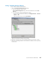
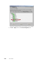
Setting Thermal Units . . . . . . . . . . . . . . . . . . . . . . . . . . . . . . . . . . . . . . . . . . . . . . . . . . . . .
Deploying a PAM Release . . . . . . . . . . . . . . . . . . . . . . . . . . . . . . . . . . . . . . . . . . . . . . . . .
Activating a PAM Version . . . . . . . . . . . . . . . . . . . . . . . . . . . . . . . . . . . . . . . . . . . . . . . . .
Backing Up and Restoring PAM Configuration Files . . . . . . . . . . . . . . . . . . . . . . . . . . .
Backing Up PAM Configuration Files . . . . . . . . . . . . . . . . . . . . . . . . . . . . . . . . . . . . .
Restoring PAM Configuration Data . . . . . . . . . . . . . . . . . . . . . . . . . . . . . . . . . . . . . . .
Partitioning your Server . . . . . . . . . . . . . . . . . . . . . . . . . . . . . . . . . . . . . . . . . . . . . . . . . . .
Assessing Configuration Requirements . . . . . . . . . . . . . . . . . . . . . . . . . . . . . . . . . . . . . . .
Managing Domain Configuration Schemes . . . . . . . . . . . . . . . . . . . . . . . . . . . . . . . . . .
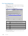
Creating a Domain Configuration Scheme . . . . . . . . . . . . . . . . . . . . . . . . . . . . . . . .
Editing a Domain Configuration Scheme . . . . . . . . . . . . . . . . . . . . . . . . . . . . . . . . . .
Copying a Domain Configuration Scheme . . . . . . . . . . . . . . . . . . . . . . . . . . . . . . . . .
Deleting a Domain Configuration Scheme . . . . . . . . . . . . . . . . . . . . . . . . . . . . . . . . .
Renaming a Domain Configuration Scheme . . . . . . . . . . . . . . . . . . . . . . . . . . . . . . .
Updating Default Schemes . . . . . . . . . . . . . . . . . . . . . . . . . . . . . . . . . . . . . . . . . . . . . . . . .
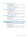
Creating, Editing, Copying, Deleting a Domain Identity . . . . . . . . . . . . . . . . . . . . . . . .
Creating a Domain Identity . . . . . . . . . . . . . . . . . . . . . . . . . . . . . . . . . . . . . . . . . . . . . .
Editing a Domain Identity . . . . . . . . . . . . . . . . . . . . . . . . . . . . . . . . . . . . . . . . . . . . . . .
Copying a Domain Identity . . . . . . . . . . . . . . . . . . . . . . . . . . . . . . . . . . . . . . . . . . . . . .
Deleting a Domain Identity . . . . . . . . . . . . . . . . . . . . . . . . . . . . . . . . . . . . . . . . . . . . . .
Managing Logical Units (Servers Not Connected to a SAN) . . . . . . . . . . . . . . . . . . . .
Updating the Local LUN Lists . . . . . . . . . . . . . . . . . . . . . . . . . . . . . . . . . . . . . . . . . . . .
Clearing, Loading, Saving NVRAM Variables . . . . . . . . . . . . . . . . . . . . . . . . . . . . . .
5-1
5-4
5-5
5-5
5-7
5-7
5-9
5-9
5-9
5-10
5-10
5-10
5-11
5-11
5-11
5-11
5-11
5-14
5-14
5-15
5-17
5-17
5-19
5-20
5-22
5-23
5-24
5-26
5-26
5-27
5-29
5-31
5-33
5-33
5-48
5-49
5-49
5-49
5-49
5-50
5-50
5-54
5-54
5-54
5-55
5-56
5-56
Preface
vii
Managing Logical Units (Servers Connected to a SAN) . . . . . . . . . . . . . . . . . . . . . . . .
Updating SAN LUN Lists . . . . . . . . . . . . . . . . . . . . . . . . . . . . . . . . . . . . . . . . . . . . . . . .
Declaring Local LUNs . . . . . . . . . . . . . . . . . . . . . . . . . . . . . . . . . . . . . . . . . . . . . . . . . .
Deleting Local LUNs . . . . . . . . . . . . . . . . . . . . . . . . . . . . . . . . . . . . . . . . . . . . . . . . . . . .
Editing LUNs . . . . . . . . . . . . . . . . . . . . . . . . . . . . . . . . . . . . . . . . . . . . . . . . . . . . . . . . . .
Renaming LUNs . . . . . . . . . . . . . . . . . . . . . . . . . . . . . . . . . . . . . . . . . . . . . . . . . . . . . . .
Clearing, Loading, Saving NVRAM Variables . . . . . . . . . . . . . . . . . . . . . . . . . . . . . .
Checking and Updating Fibre Channel HBA World Wide Names . . . . . . . . . . . . . . .
Limiting Access to Hardware Resources . . . . . . . . . . . . . . . . . . . . . . . . . . . . . . . . . . . . . .
Locking / Unlocking Hardware Elements . . . . . . . . . . . . . . . . . . . . . . . . . . . . . . . . . .
Creating a Mono-Domain Scheme Using All Server Resources . . . . . . . . . . . . . . . . . .
Creating a Mono-Domain Scheme Using a Selection of Server Resources . . . . . . . .
Creating a Multi-Domain Scheme Using All Server Resources . . . . . . . . . . . . . . . . . . .
Creating a Multi-Domain Scheme Using a Selection of Server Resources . . . . . . . . .
Configuring and Managing Extended Systems . . . . . . . . . . . . . . . . . . . . . . . . . . . . . . .
Scheme, Domain Identity, and Resources Checklists . . . . . . . . . . . . . . . . . . . . . . . . . . .
Customizing the PAM Event Messaging System . . . . . . . . . . . . . . . . . . . . . . . . . . . . . . .
Setting up Event Subscriptions . . . . . . . . . . . . . . . . . . . . . . . . . . . . . . . . . . . . . . . . . . . . . .
Event Subscription Flowcharts . . . . . . . . . . . . . . . . . . . . . . . . . . . . . . . . . . . . . . . . . . . . . .
Creating, Editing, Deleting an E-mail Server . . . . . . . . . . . . . . . . . . . . . . . . . . . . . . . . . .
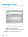
Creating an E-mail Server . . . . . . . . . . . . . . . . . . . . . . . . . . . . . . . . . . . . . . . . . . . . . . .
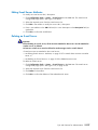
Editing E-mail Server Attributes . . . . . . . . . . . . . . . . . . . . . . . . . . . . . . . . . . . . . . . . . . .
Deleting an E-mail Server . . . . . . . . . . . . . . . . . . . . . . . . . . . . . . . . . . . . . . . . . . . . . . .
Creating, Editing, Deleting an E-mail Account . . . . . . . . . . . . . . . . . . . . . . . . . . . . . . . .
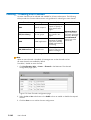
Creating an E-mail Account . . . . . . . . . . . . . . . . . . . . . . . . . . . . . . . . . . . . . . . . . . . . .
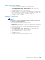
Editing E-mail Account Attributes . . . . . . . . . . . . . . . . . . . . . . . . . . . . . . . . . . . . . . . . .
Deleting an E-mail Account . . . . . . . . . . . . . . . . . . . . . . . . . . . . . . . . . . . . . . . . . . . . . .
Enabling / Disabling Event Channels . . . . . . . . . . . . . . . . . . . . . . . . . . . . . . . . . . . . . . .
Creating, Editing, Deleting an Event Subscription . . . . . . . . . . . . . . . . . . . . . . . . . . . . .
Creating an Event Subscription . . . . . . . . . . . . . . . . . . . . . . . . . . . . . . . . . . . . . . . . . .
Editing Event Subscription Attributes . . . . . . . . . . . . . . . . . . . . . . . . . . . . . . . . . . . . . .
Deleting an Event Subscription . . . . . . . . . . . . . . . . . . . . . . . . . . . . . . . . . . . . . . . . . . .
Understanding Event Message Filtering Criteria . . . . . . . . . . . . . . . . . . . . . . . . . . . . . . .
Standard Event Message Filtering Criteria . . . . . . . . . . . . . . . . . . . . . . . . . . . . . . . . . . .
Advanced Event Message Filtering Criteria . . . . . . . . . . . . . . . . . . . . . . . . . . . . . . . . . .
Preselecting, Creating, Editing, Deleting an Event Filter . . . . . . . . . . . . . . . . . . . . . . . .
Preselecting an Event Filter . . . . . . . . . . . . . . . . . . . . . . . . . . . . . . . . . . . . . . . . . . . . . .
Creating an Event Filter . . . . . . . . . . . . . . . . . . . . . . . . . . . . . . . . . . . . . . . . . . . . . . . . .
Editing Event Filter Attributes . . . . . . . . . . . . . . . . . . . . . . . . . . . . . . . . . . . . . . . . . . . . .
Deleting an Event Filter . . . . . . . . . . . . . . . . . . . . . . . . . . . . . . . . . . . . . . . . . . . . . . . . .
Creating, Editing, Deleting a User History . . . . . . . . . . . . . . . . . . . . . . . . . . . . . . . . . . .
Creating a User History . . . . . . . . . . . . . . . . . . . . . . . . . . . . . . . . . . . . . . . . . . . . . . . . .
Editing History Parameters . . . . . . . . . . . . . . . . . . . . . . . . . . . . . . . . . . . . . . . . . . . . . .
Deleting a User History . . . . . . . . . . . . . . . . . . . . . . . . . . . . . . . . . . . . . . . . . . . . . . . . .
5-57
5-59
5-60
5-61
5-62
5-63
5-63
5-64
5-66
5-67
5-69
5-83
5-96
5-111
5-125
5-126
5-133
5-134
5-135
5-136
5-136
5-137
5-137
5-138
5-138
5-139
5-139
5-140
5-141
5-141
5-142
5-142
5-143
5-145
5-148
5-153
5-153
5-154
5-155
5-155
5-156
5-157
5-158
5-159
Appendix A. Specifications . . . . . . . . . . . . . . . . . . . . . . . . . . . . . . . . . . . . . . . . . . . . . . . .
NovaScale 5085 Server Specifications . . . . . . . . . . . . . . . . . . . . . . . . . . . . . . . . . . . . . .
NovaScale 5165 Server Specifications . . . . . . . . . . . . . . . . . . . . . . . . . . . . . . . . . . . . . .
NovaScale 5245 Server Specifications . . . . . . . . . . . . . . . . . . . . . . . . . . . . . . . . . . . . . .
NovaScale 5325 Server Specifications . . . . . . . . . . . . . . . . . . . . . . . . . . . . . . . . . . . . . .
A-1
A-2
A-4
A-6
A-8
Glossary . . . . . . . . . . . . . . . . . . . . . . . . . . . . . . . . . . . . . . . . . . . . . . . . . . . . . . . . . . . . . . . .
G-1
viii User's Guide
Index . . . . . . . . . . . . . . . . . . . . . . . . . . . . . . . . . . . . . . . . . . . . . . . . . . . . . . . . . . . . . . . . . . .
Preface
X-1
ix
x
User's Guide
List of Figures
Figure
Figure
Figure
Figure
Figure
Figure
Figure
Figure
Figure
Figure
Figure
Figure
Figure
Figure
Figure
Figure
Figure
Figure
Figure
Figure
Figure
Figure
Figure
Figure
Figure
Figure
Figure
Figure
Figure
Figure
Figure
Figure
Figure
Figure
Figure
Figure
Figure
Figure
Figure
Figure
Figure
Figure
Figure
Figure
Figure
Figure
1.
2.
3.
4.
5.
6.
7.
8.
9.
10.
11.
12.
13.
14.
15.
16.
17.
18.
19.
20.
21.
22.
23.
24.
25.
26.
27.
28.
29.
30.
31.
32.
33.
34.
35.
36.
37.
38.
39.
40.
41.
42.
43.
44.
45.
46.
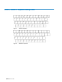
AZERTY keyboard . . . . . . . . . . . . . . . . . . . . . . . . . . . . . . . . . . . . . . . . . . . . . . . . . . . . . . . . . . .
QWERTY keyboard . . . . . . . . . . . . . . . . . . . . . . . . . . . . . . . . . . . . . . . . . . . . . . . . . . . . . . . . . .
Bull NovaScale Server cabinets . . . . . . . . . . . . . . . . . . . . . . . . . . . . . . . . . . . . . . . . . . . . . . . .
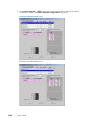
NovaScale 5085 Partitioned Server components - example . . . . . . . . . . . . . . . . . . . . . . . .
NovaScale 5165 Partitioned Server components - example . . . . . . . . . . . . . . . . . . . . . . . .
NovaScale 5245 Partitioned Server components - example . . . . . . . . . . . . . . . . . . . . . . . .
NovaScale 5325 Partitioned Servers components - example . . . . . . . . . . . . . . . . . . . . . . .
NovaScale 5325 Partitioned Servers components - example . . . . . . . . . . . . . . . . . . . . . . .
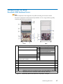
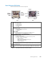
CSS module features (full CSS module example) . . . . . . . . . . . . . . . . . . . . . . . . . . . . . . . . .
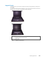
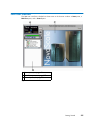
PAP unit . . . . . . . . . . . . . . . . . . . . . . . . . . . . . . . . . . . . . . . . . . . . . . . . . . . . . . . . . . . . . . . . . . . .
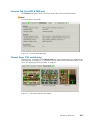
Integrated console features . . . . . . . . . . . . . . . . . . . . . . . . . . . . . . . . . . . . . . . . . . . . . . . . . . . .
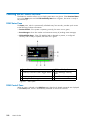
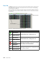
8-port KVM switch features . . . . . . . . . . . . . . . . . . . . . . . . . . . . . . . . . . . . . . . . . . . . . . . . . . . .
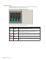
16-port KVM switch features . . . . . . . . . . . . . . . . . . . . . . . . . . . . . . . . . . . . . . . . . . . . . . . . . .
KVM extender (local & remote) 300m maxi. . . . . . . . . . . . . . . . . . . . . . . . . . . . . . . . . . . . . .
FDA 1x00 FC disk rack features . . . . . . . . . . . . . . . . . . . . . . . . . . . . . . . . . . . . . . . . . . . . . . .
FDA 2x00 FC disk rack features . . . . . . . . . . . . . . . . . . . . . . . . . . . . . . . . . . . . . . . . . . . . . . .
FDA 1x00 FC extension disk rack features . . . . . . . . . . . . . . . . . . . . . . . . . . . . . . . . . . . . . .
Ethernet hub features . . . . . . . . . . . . . . . . . . . . . . . . . . . . . . . . . . . . . . . . . . . . . . . . . . . . . . . . .
USB modem features . . . . . . . . . . . . . . . . . . . . . . . . . . . . . . . . . . . . . . . . . . . . . . . . . . . . . . . . .
NPort Server features . . . . . . . . . . . . . . . . . . . . . . . . . . . . . . . . . . . . . . . . . . . . . . . . . . . . . . . . .
Opening the front door . . . . . . . . . . . . . . . . . . . . . . . . . . . . . . . . . . . . . . . . . . . . . . . . . . . . . . .
Integrated console example . . . . . . . . . . . . . . . . . . . . . . . . . . . . . . . . . . . . . . . . . . . . . . . . . . .
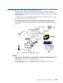
PAM software deployment . . . . . . . . . . . . . . . . . . . . . . . . . . . . . . . . . . . . . . . . . . . . . . . . . . . .
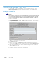
PAM Web site session details . . . . . . . . . . . . . . . . . . . . . . . . . . . . . . . . . . . . . . . . . . . . . . . . . .
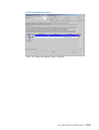
Multiple session example . . . . . . . . . . . . . . . . . . . . . . . . . . . . . . . . . . . . . . . . . . . . . . . . . . . . .
PAM user interface . . . . . . . . . . . . . . . . . . . . . . . . . . . . . . . . . . . . . . . . . . . . . . . . . . . . . . . . . . .
Status pane . . . . . . . . . . . . . . . . . . . . . . . . . . . . . . . . . . . . . . . . . . . . . . . . . . . . . . . . . . . . . . . . .
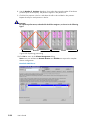
CSS Module availability status bar (bi-module server) . . . . . . . . . . . . . . . . . . . . . . . . . . . . .
PAM Tree toolbar . . . . . . . . . . . . . . . . . . . . . . . . . . . . . . . . . . . . . . . . . . . . . . . . . . . . . . . . . . . .
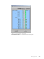
Domain Manager Control pane . . . . . . . . . . . . . . . . . . . . . . . . . . . . . . . . . . . . . . . . . . . . . . . .
Domain state . . . . . . . . . . . . . . . . . . . . . . . . . . . . . . . . . . . . . . . . . . . . . . . . . . . . . . . . . . . . . . . .
Domain schemes list dialog . . . . . . . . . . . . . . . . . . . . . . . . . . . . . . . . . . . . . . . . . . . . . . . . . . .
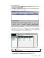
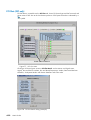
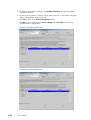
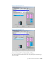
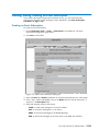
Domain Manager Control pane - example with 4 domains . . . . . . . . . . . . . . . . . . . . . . . .
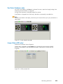
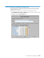
Multiple power dialog - example with 4 domains . . . . . . . . . . . . . . . . . . . . . . . . . . . . . . . . .
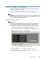
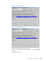
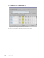
Domain state - example with 4 domains . . . . . . . . . . . . . . . . . . . . . . . . . . . . . . . . . . . . . . . . .
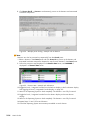
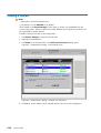
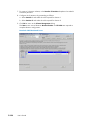
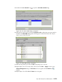
Schemes list dialog . . . . . . . . . . . . . . . . . . . . . . . . . . . . . . . . . . . . . . . . . . . . . . . . . . . . . . . . . .
Scheme properties dialog - Example with 4 domains . . . . . . . . . . . . . . . . . . . . . . . . . . . . .
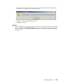
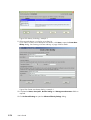
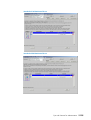
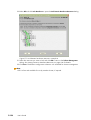
Schemes list dialog . . . . . . . . . . . . . . . . . . . . . . . . . . . . . . . . . . . . . . . . . . . . . . . . . . . . . . . . . .
Domain Manager control pane - Example with 4 domains . . . . . . . . . . . . . . . . . . . . . . . . .
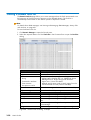
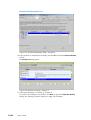
Domain Infotip . . . . . . . . . . . . . . . . . . . . . . . . . . . . . . . . . . . . . . . . . . . . . . . . . . . . . . . . . . . . . .
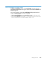
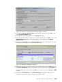
Save Snapshot dialog . . . . . . . . . . . . . . . . . . . . . . . . . . . . . . . . . . . . . . . . . . . . . . . . . . . . . . . .
Multiple power dialog - quadri-domain example . . . . . . . . . . . . . . . . . . . . . . . . . . . . . . . . .
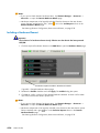
Multiple power dialog - quadri-domain example . . . . . . . . . . . . . . . . . . . . . . . . . . . . . . . . .
Multiple power dialog - quadri-domain example . . . . . . . . . . . . . . . . . . . . . . . . . . . . . . . . .
Delete domain dialog - mono-module server . . . . . . . . . . . . . . . . . . . . . . . . . . . . . . . . . . . . .
Delete Domain dialog - Example with 4 domains . . . . . . . . . . . . . . . . . . . . . . . . . . . . . . . . .
Preface
xxii
xxii
1-2
1-7
1-8
1-9
1-10
1-11
1-13
1-14
1-15
1-16
1-16
1-16
1-17
1-17
1-18
1-19
1-19
1-19
1-20
1-21
1-22
2-4
2-4
2-5
2-6
2-7
2-8
2-10
2-11
2-13
2-13
2-14
2-14
3-7
3-7
3-8
3-9
3-9
3-11
3-16
3-19
3-23
3-26
3-26
xi
Figure
Figure
Figure
Figure
Figure
Figure
Figure
Figure
Figure
Figure
Figure
Figure
Figure
Figure
Figure
Figure
Figure
Figure
Figure
Figure
Figure
Figure
Figure
Figure
Figure
Figure
Figure
Figure
Figure
Figure
Figure
Figure
Figure
Figure
Figure
Figure
Figure
Figure
Figure
Figure
Figure
Figure
Figure
Figure
Figure
Figure
Figure
Figure
Figure
47.
48.
49.
50.
51.
52.
53.
54.
55.
56.
57.
58.
59.
60.
61.
62.
63.
64.
65.
66.
67.
68.
69.
70.
71.
72.
73.
74.
75.
76.
77.
78.
79.
80.
81.
82.
83.
84.
85.
86.
87.
88.
89.
90.
91.
92.
93.
94.
95.
Domain deleted information box . . . . . . . . . . . . . . . . . . . . . . . . . . . . . . . . . . . . . . . . . . . . . . .
Domain fault list dialog - example . . . . . . . . . . . . . . . . . . . . . . . . . . . . . . . . . . . . . . . . . . . . . .
Power logs dialog . . . . . . . . . . . . . . . . . . . . . . . . . . . . . . . . . . . . . . . . . . . . . . . . . . . . . . . . . . .
Powering view dialog . . . . . . . . . . . . . . . . . . . . . . . . . . . . . . . . . . . . . . . . . . . . . . . . . . . . . . . .
BIOS Info dialog . . . . . . . . . . . . . . . . . . . . . . . . . . . . . . . . . . . . . . . . . . . . . . . . . . . . . . . . . . . . .
Request Logs dialog . . . . . . . . . . . . . . . . . . . . . . . . . . . . . . . . . . . . . . . . . . . . . . . . . . . . . . . . . .
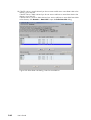
View Domain dialog - example . . . . . . . . . . . . . . . . . . . . . . . . . . . . . . . . . . . . . . . . . . . . . . . .
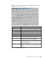
View Domain dialog 1/2 . . . . . . . . . . . . . . . . . . . . . . . . . . . . . . . . . . . . . . . . . . . . . . . . . . . . .
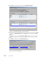
View Domain dialog 2/2 . . . . . . . . . . . . . . . . . . . . . . . . . . . . . . . . . . . . . . . . . . . . . . . . . . . . .
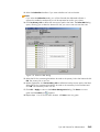
Domain Hardware Resources dialog . . . . . . . . . . . . . . . . . . . . . . . . . . . . . . . . . . . . . . . . . . . .
Domain Hardware Details dialog . . . . . . . . . . . . . . . . . . . . . . . . . . . . . . . . . . . . . . . . . . . . . .
PAM Status pane . . . . . . . . . . . . . . . . . . . . . . . . . . . . . . . . . . . . . . . . . . . . . . . . . . . . . . . . . . . .
CSS Module availability status bar . . . . . . . . . . . . . . . . . . . . . . . . . . . . . . . . . . . . . . . . . . . . .
PAM Tree hardware presence status display . . . . . . . . . . . . . . . . . . . . . . . . . . . . . . . . . . . . .
PAM Tree functional status display . . . . . . . . . . . . . . . . . . . . . . . . . . . . . . . . . . . . . . . . . . . . .
PAM Tree - automatically expanded functional status display . . . . . . . . . . . . . . . . . . . . . . .
Hardware Search engine . . . . . . . . . . . . . . . . . . . . . . . . . . . . . . . . . . . . . . . . . . . . . . . . . . . . .
Hardware Search result list (example) . . . . . . . . . . . . . . . . . . . . . . . . . . . . . . . . . . . . . . . . . .
PAM Web Site user information . . . . . . . . . . . . . . . . . . . . . . . . . . . . . . . . . . . . . . . . . . . . . . . .
PAP unit information . . . . . . . . . . . . . . . . . . . . . . . . . . . . . . . . . . . . . . . . . . . . . . . . . . . . . . . . . .
PAM Hardware Monitor . . . . . . . . . . . . . . . . . . . . . . . . . . . . . . . . . . . . . . . . . . . . . . . . . . . . . .
General Hardware Status page (example) . . . . . . . . . . . . . . . . . . . . . . . . . . . . . . . . . . . . . . .
FRU data (example) . . . . . . . . . . . . . . . . . . . . . . . . . . . . . . . . . . . . . . . . . . . . . . . . . . . . . . . . . .
Firmware data (example) . . . . . . . . . . . . . . . . . . . . . . . . . . . . . . . . . . . . . . . . . . . . . . . . . . . . .
CSS module thermal zone details . . . . . . . . . . . . . . . . . . . . . . . . . . . . . . . . . . . . . . . . . . . . . .
Converter power status details (example) . . . . . . . . . . . . . . . . . . . . . . . . . . . . . . . . . . . . . . . .
CSS module power status details . . . . . . . . . . . . . . . . . . . . . . . . . . . . . . . . . . . . . . . . . . . . . . .
Temperature probe status details (example) . . . . . . . . . . . . . . . . . . . . . . . . . . . . . . . . . . . . . .
Fanbox details (example) . . . . . . . . . . . . . . . . . . . . . . . . . . . . . . . . . . . . . . . . . . . . . . . . . . . . .
IO Box jumpers tab . . . . . . . . . . . . . . . . . . . . . . . . . . . . . . . . . . . . . . . . . . . . . . . . . . . . . . . . . .
PCI slot status . . . . . . . . . . . . . . . . . . . . . . . . . . . . . . . . . . . . . . . . . . . . . . . . . . . . . . . . . . . . . . .
PCI slot details dialog (example) . . . . . . . . . . . . . . . . . . . . . . . . . . . . . . . . . . . . . . . . . . . . . . .
Inclusion . . . . . . . . . . . . . . . . . . . . . . . . . . . . . . . . . . . . . . . . . . . . . . . . . . . . . . . . . . . . . . . . . . . .
Example Hardware Status page . . . . . . . . . . . . . . . . . . . . . . . . . . . . . . . . . . . . . . . . . . . . . . .
Ring exlcusion control pane - clock tab . . . . . . . . . . . . . . . . . . . . . . . . . . . . . . . . . . . . . . . . .
Ring exclusion control pane - SPS tab . . . . . . . . . . . . . . . . . . . . . . . . . . . . . . . . . . . . . . . . . . .
Ring exclusion control pane - XSP cable tab . . . . . . . . . . . . . . . . . . . . . . . . . . . . . . . . . . . . .
Ring exclusion control pane - sideband tab . . . . . . . . . . . . . . . . . . . . . . . . . . . . . . . . . . . . . .
Display Events page . . . . . . . . . . . . . . . . . . . . . . . . . . . . . . . . . . . . . . . . . . . . . . . . . . . . . . . . . .
Specimen message help file . . . . . . . . . . . . . . . . . . . . . . . . . . . . . . . . . . . . . . . . . . . . . . . . . . .
History Manager Control pane - Histories tab . . . . . . . . . . . . . . . . . . . . . . . . . . . . . . . . . . . .
History properties . . . . . . . . . . . . . . . . . . . . . . . . . . . . . . . . . . . . . . . . . . . . . . . . . . . . . . . . . . . .
History Manager Control pane - Archived histories tab . . . . . . . . . . . . . . . . . . . . . . . . . . . .
Archive properties . . . . . . . . . . . . . . . . . . . . . . . . . . . . . . . . . . . . . . . . . . . . . . . . . . . . . . . . . . .
PMB LED location . . . . . . . . . . . . . . . . . . . . . . . . . . . . . . . . . . . . . . . . . . . . . . . . . . . . . . . . . . . .
Action Request Package control pane . . . . . . . . . . . . . . . . . . . . . . . . . . . . . . . . . . . . . . . . . . .
Action Request Package details . . . . . . . . . . . . . . . . . . . . . . . . . . . . . . . . . . . . . . . . . . . . . . . .
Custom Package control pane . . . . . . . . . . . . . . . . . . . . . . . . . . . . . . . . . . . . . . . . . . . . . . . . .
Custom Package Add files pane . . . . . . . . . . . . . . . . . . . . . . . . . . . . . . . . . . . . . . . . . . . . . . .
xii User's Guide
3-27
3-28
3-31
3-32
3-33
3-34
3-35
3-36
3-37
3-38
3-39
4-3
4-4
4-5
4-7
4-9
4-10
4-11
4-12
4-13
4-14
4-15
4-16
4-17
4-17
4-18
4-19
4-20
4-21
4-21
4-22
4-22
4-23
4-24
4-27
4-28
4-29
4-30
4-33
4-34
4-36
4-37
4-38
4-39
4-50
4-51
4-53
4-54
4-55
Figure
Figure
Figure
Figure
Figure
Figure
Figure
Figure
Figure
Figure
Figure
Figure
Figure
Figure
Figure
Figure
Figure
Figure
Figure
Figure
Figure
Figure
Figure
Figure
Figure
Figure
Figure
Figure
Figure
Figure
Figure
Figure
Figure
Figure
Figure
Figure
Figure
Figure
Figure
Figure
Figure
Figure
Figure
Figure
Figure
Figure
Figure
Figure
Figure
96. Customer Information configuration page . . . . . . . . . . . . . . . . . . . . . . . . . . . . . . . . . . . . . . .
97. Autocalls Channel Settings control pane . . . . . . . . . . . . . . . . . . . . . . . . . . . . . . . . . . . . . . . .
98. PAM configuration control pane . . . . . . . . . . . . . . . . . . . . . . . . . . . . . . . . . . . . . . . . . . . . . . .
99. PAM Installation InstallShield Wizard . . . . . . . . . . . . . . . . . . . . . . . . . . . . . . . . . . . . . . . . . . .
100. PAM Activation InstallShield Wizard . . . . . . . . . . . . . . . . . . . . . . . . . . . . . . . . . . . . . . . . . . . .
101. Schemes and Identites panes . . . . . . . . . . . . . . . . . . . . . . . . . . . . . . . . . . . . . . . . . . . . . . . . . .
102. Schemes control pane . . . . . . . . . . . . . . . . . . . . . . . . . . . . . . . . . . . . . . . . . . . . . . . . . . . . . . . .
103. Scheme Management dialog . . . . . . . . . . . . . . . . . . . . . . . . . . . . . . . . . . . . . . . . . . . . . . . . . .
104. Scheme Creation and Central Subsystem Configuration dialogs . . . . . . . . . . . . . . . . . . . .
105. Optimizing partitioning . . . . . . . . . . . . . . . . . . . . . . . . . . . . . . . . . . . . . . . . . . . . . . . . . . . . . . .
106. Scheme Management dialog - Central Subsystem configured . . . . . . . . . . . . . . . . . . . . . .
107. Domain Identities list . . . . . . . . . . . . . . . . . . . . . . . . . . . . . . . . . . . . . . . . . . . . . . . . . . . . . . . . .
108. EFI LUN selection list . . . . . . . . . . . . . . . . . . . . . . . . . . . . . . . . . . . . . . . . . . . . . . . . . . . . . . . . .
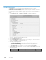
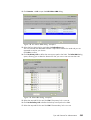
109. Select Data LUN dialog - Data luns available list . . . . . . . . . . . . . . . . . . . . . . . . . . . . . . . . .
110. View LUN parameters dialog . . . . . . . . . . . . . . . . . . . . . . . . . . . . . . . . . . . . . . . . . . . . . . . . . .
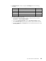
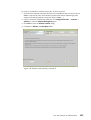
111. Select Data LUN dialog - Data luns selected list . . . . . . . . . . . . . . . . . . . . . . . . . . . . . . . . . .
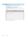
112. Link LUNs to HBA dialog . . . . . . . . . . . . . . . . . . . . . . . . . . . . . . . . . . . . . . . . . . . . . . . . . . . . .
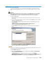
113. Select an HBA dialog . . . . . . . . . . . . . . . . . . . . . . . . . . . . . . . . . . . . . . . . . . . . . . . . . . . . . . . .
114. Scheme Management dialog . . . . . . . . . . . . . . . . . . . . . . . . . . . . . . . . . . . . . . . . . . . . . . . . . .
115. Edit Scheme dialog . . . . . . . . . . . . . . . . . . . . . . . . . . . . . . . . . . . . . . . . . . . . . . . . . . . . . . . . . .
116. Identities List page . . . . . . . . . . . . . . . . . . . . . . . . . . . . . . . . . . . . . . . . . . . . . . . . . . . . . . . . . . .
117. Create New Identity dialog . . . . . . . . . . . . . . . . . . . . . . . . . . . . . . . . . . . . . . . . . . . . . . . . . . .
118. Advanced Identity Settings dialog . . . . . . . . . . . . . . . . . . . . . . . . . . . . . . . . . . . . . . . . . . . . . .
119. Logical Units page - servers not connected to a SAN . . . . . . . . . . . . . . . . . . . . . . . . . . . . .
120. Logical Units page - servers connected to a SAN . . . . . . . . . . . . . . . . . . . . . . . . . . . . . . . . .
121. SAN Update progress bar . . . . . . . . . . . . . . . . . . . . . . . . . . . . . . . . . . . . . . . . . . . . . . . . . . . .
122. Declare Local LUN dialog . . . . . . . . . . . . . . . . . . . . . . . . . . . . . . . . . . . . . . . . . . . . . . . . . . . . .
123. Delete LUN dialog . . . . . . . . . . . . . . . . . . . . . . . . . . . . . . . . . . . . . . . . . . . . . . . . . . . . . . . . . . .
124. Edit LUN dialog . . . . . . . . . . . . . . . . . . . . . . . . . . . . . . . . . . . . . . . . . . . . . . . . . . . . . . . . . . . . .
125. Rename LUN dialog . . . . . . . . . . . . . . . . . . . . . . . . . . . . . . . . . . . . . . . . . . . . . . . . . . . . . . . . . .
126. HBA Worldwide Name page . . . . . . . . . . . . . . . . . . . . . . . . . . . . . . . . . . . . . . . . . . . . . . . . . .
127. Modify PCI HBA Worldwide Name dialog . . . . . . . . . . . . . . . . . . . . . . . . . . . . . . . . . . . . . .
128. Lock domain hardware resources dialog . . . . . . . . . . . . . . . . . . . . . . . . . . . . . . . . . . . . . . . .
129. Lock domain hardware resources dialog - PCI slot selected . . . . . . . . . . . . . . . . . . . . . . . .
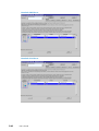
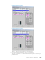
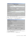
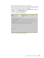
130. Scheme creation dialog - example 1 . . . . . . . . . . . . . . . . . . . . . . . . . . . . . . . . . . . . . . . . . . .
131. Central Subsystem configuration dialog - example 1 . . . . . . . . . . . . . . . . . . . . . . . . . . . . . .
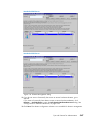
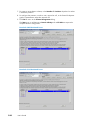
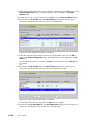
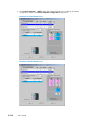
132. Scheme Management dialog - example 1 . . . . . . . . . . . . . . . . . . . . . . . . . . . . . . . . . . . . . . .
133. Identity list dialog - example 1 . . . . . . . . . . . . . . . . . . . . . . . . . . . . . . . . . . . . . . . . . . . . . . . . .
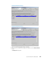
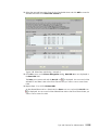
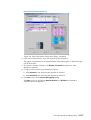
134. Create new identity dialog - example 1 . . . . . . . . . . . . . . . . . . . . . . . . . . . . . . . . . . . . . . . . .
135. Create new identity advanced setting dialog - example 1 . . . . . . . . . . . . . . . . . . . . . . . . .
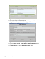
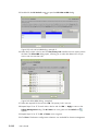
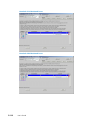
136. Select EFI LUN dialog - example 1 . . . . . . . . . . . . . . . . . . . . . . . . . . . . . . . . . . . . . . . . . . . . .
137. Select Data LUN dialog - example 1 . . . . . . . . . . . . . . . . . . . . . . . . . . . . . . . . . . . . . . . . . . . .
138. Link LUN to HBA dialog - example 1 . . . . . . . . . . . . . . . . . . . . . . . . . . . . . . . . . . . . . . . . . . .
139. Select HBA dialog - example 1 . . . . . . . . . . . . . . . . . . . . . . . . . . . . . . . . . . . . . . . . . . . . . . . .
140. Scheme creation dialog - example 2 . . . . . . . . . . . . . . . . . . . . . . . . . . . . . . . . . . . . . . . . . . .
141. Central Subsystem configuration dialog - example 2 . . . . . . . . . . . . . . . . . . . . . . . . . . . . . .
142. Scheme Management dialog - example 2 . . . . . . . . . . . . . . . . . . . . . . . . . . . . . . . . . . . . . . .
143. Identity list dialog - example 2 . . . . . . . . . . . . . . . . . . . . . . . . . . . . . . . . . . . . . . . . . . . . . . . . .
144. Create new identity advanced setting dialog - example 2 . . . . . . . . . . . . . . . . . . . . . . . . .
Preface
xiii
5-19
5-20
5-22
5-23
5-24
5-30
5-34
5-35
5-37
5-38
5-40
5-40
5-41
5-42
5-43
5-44
5-44
5-45
5-47
5-48
5-50
5-51
5-52
5-55
5-58
5-59
5-60
5-61
5-62
5-63
5-64
5-65
5-67
5-68
5-73
5-75
5-77
5-78
5-78
5-79
5-79
5-80
5-81
5-81
5-87
5-89
5-91
5-92
5-92
Figure
Figure
Figure
Figure
Figure
Figure
Figure
Figure
Figure
Figure
Figure
Figure
Figure
Figure
Figure
Figure
Figure
Figure
Figure
Figure
Figure
Figure
Figure
Figure
Figure
Figure
Figure
Figure
Figure
Figure
Figure
Figure
Figure
Figure
Figure
Figure
Figure
Figure
145. Create new identity advanced setting dialog - example 2 . . . . . . . . . . . . . . . . . . . . . . . . .
146. Select EFI LUN dialog - example 2 . . . . . . . . . . . . . . . . . . . . . . . . . . . . . . . . . . . . . . . . . . . . .
147. Select Data LUN dialog - example 2 . . . . . . . . . . . . . . . . . . . . . . . . . . . . . . . . . . . . . . . . . . . .
148. Link LUN to HBA dialog - example 2 . . . . . . . . . . . . . . . . . . . . . . . . . . . . . . . . . . . . . . . . . . .
149. Select HBA dialog - example 2 . . . . . . . . . . . . . . . . . . . . . . . . . . . . . . . . . . . . . . . . . . . . . . . .
150. Scheme creation dialog - example 3 . . . . . . . . . . . . . . . . . . . . . . . . . . . . . . . . . . . . . . . . . . .
151. Central Subsystem configuration dialog - example 3 . . . . . . . . . . . . . . . . . . . . . . . . . . . . . .
152. Scheme Management dialog - example 3 . . . . . . . . . . . . . . . . . . . . . . . . . . . . . . . . . . . . . . .
153. Identities list dialog - example 3 . . . . . . . . . . . . . . . . . . . . . . . . . . . . . . . . . . . . . . . . . . . . . . .
154. Create new identity dialog - example 3 . . . . . . . . . . . . . . . . . . . . . . . . . . . . . . . . . . . . . . . . .
155. Create new identity advanced setting dialog - example 3 . . . . . . . . . . . . . . . . . . . . . . . . .
156. Select SAN EFI LUN dialog - example 3 . . . . . . . . . . . . . . . . . . . . . . . . . . . . . . . . . . . . . . . .
157. Select Local EFI LUN dialog - example 3 . . . . . . . . . . . . . . . . . . . . . . . . . . . . . . . . . . . . . . . .
158. Select Data LUN dialog - example 2 . . . . . . . . . . . . . . . . . . . . . . . . . . . . . . . . . . . . . . . . . . . .
159. Link LUN to HBA dialog - example 3 . . . . . . . . . . . . . . . . . . . . . . . . . . . . . . . . . . . . . . . . . . .
160. Select HBA dialog - example 3 . . . . . . . . . . . . . . . . . . . . . . . . . . . . . . . . . . . . . . . . . . . . . . . .
161. Scheme creation dialog - example 4 . . . . . . . . . . . . . . . . . . . . . . . . . . . . . . . . . . . . . . . . . . .
162. Central Subsystem configuration dialog - example 4 . . . . . . . . . . . . . . . . . . . . . . . . . . . . . .
163. Scheme Management dialog - example 4 . . . . . . . . . . . . . . . . . . . . . . . . . . . . . . . . . . . . . . .
164. Identities list dialog - example 4 . . . . . . . . . . . . . . . . . . . . . . . . . . . . . . . . . . . . . . . . . . . . . . .
165. Create new identity dialog - example4 . . . . . . . . . . . . . . . . . . . . . . . . . . . . . . . . . . . . . . . . . .
166. Create new identity advanced setting dialog - example 4 . . . . . . . . . . . . . . . . . . . . . . . . .
167. Select EFI LUN dialog - example 4 . . . . . . . . . . . . . . . . . . . . . . . . . . . . . . . . . . . . . . . . . . . . .
168. Select Data LUN dialog - example 4 . . . . . . . . . . . . . . . . . . . . . . . . . . . . . . . . . . . . . . . . . . . .
169. Link LUN to HBA dialog - example 2 . . . . . . . . . . . . . . . . . . . . . . . . . . . . . . . . . . . . . . . . . . .
170. Select HBA dialog - example 4 . . . . . . . . . . . . . . . . . . . . . . . . . . . . . . . . . . . . . . . . . . . . . . . .
171. Lock domain hardware resources - example 4 . . . . . . . . . . . . . . . . . . . . . . . . . . . . . . . . . . .
172. PAM event messaging system features . . . . . . . . . . . . . . . . . . . . . . . . . . . . . . . . . . . . . . . . . .
173. E-mail servers configuration page . . . . . . . . . . . . . . . . . . . . . . . . . . . . . . . . . . . . . . . . . . . . . .
174. E-mail accounts configuration page . . . . . . . . . . . . . . . . . . . . . . . . . . . . . . . . . . . . . . . . . . . . .
175. Event Channels configuration page . . . . . . . . . . . . . . . . . . . . . . . . . . . . . . . . . . . . . . . . . . . . .
176. New Event Subscription dialog box . . . . . . . . . . . . . . . . . . . . . . . . . . . . . . . . . . . . . . . . . . . .
177. Event message standard filtering criteria chart . . . . . . . . . . . . . . . . . . . . . . . . . . . . . . . . . . .
178. Event message advanced filtering criteria chart . . . . . . . . . . . . . . . . . . . . . . . . . . . . . . . . . .
179. Filters configuration page . . . . . . . . . . . . . . . . . . . . . . . . . . . . . . . . . . . . . . . . . . . . . . . . . . . . .
180. New Filter configuration page - standard event message filtering criteria table . . . . . . .
181. New Filter configuration page - advanced event message filtering criteria table . . . . . .
182. Create a New User History dialog . . . . . . . . . . . . . . . . . . . . . . . . . . . . . . . . . . . . . . . . . . . . .
xiv User's Guide
5-93
5-93
5-94
5-95
5-95
5-101
5-103
5-106
5-106
5-107
5-107
5-108
5-108
5-109
5-110
5-110
5-115
5-117
5-119
5-120
5-120
5-121
5-121
5-122
5-123
5-123
5-124
5-133
5-136
5-138
5-140
5-141
5-143
5-144
5-153
5-154
5-155
5-157
List of Tables
Table
Table
Table
Table
Table
Table
Table
Table
Table
Table
Table
Table
Table
Table
Table
Table
Table
Table
Table
Table
Table
Table
Table
Table
Table
Table
Table
Table
Table
Table
Table
Table
Table
Table
Table
Table
Table
Table
Table
Table
Table
Table
Table
Table
Table
Table
1.
2.
3.
4.
5.
6.
7.
8.
9.
10.
11.
12.
13.
14.
15.
16.
17.
18.
19.
20.
21.
22.
23.
24.
25.
26.
27.
28.
29.
30.
31.
32.
33.
34.
35.
36.
37.
38.
39.
40.
41.
42.
43.
44.
45.
46.
PAM illegal characters . . . . . . . . . . . . . . . . . . . . . . . . . . . . . . . . . . . . . . . . . . . . . . . . . . . . . . . .
String length rules . . . . . . . . . . . . . . . . . . . . . . . . . . . . . . . . . . . . . . . . . . . . . . . . . . . . . . . . . . . .
PAM Tree nodes . . . . . . . . . . . . . . . . . . . . . . . . . . . . . . . . . . . . . . . . . . . . . . . . . . . . . . . . . . . . .
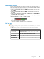
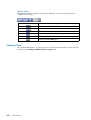
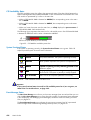
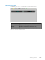
KVM port configuration . . . . . . . . . . . . . . . . . . . . . . . . . . . . . . . . . . . . . . . . . . . . . . . . . . . . . . .
PAM Domain Manager tools . . . . . . . . . . . . . . . . . . . . . . . . . . . . . . . . . . . . . . . . . . . . . . . . . .
MyOperations Scheme organization - NovaScale 5xx5 Partitioned Servers . . . . . . . . . .
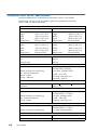
Power-on states . . . . . . . . . . . . . . . . . . . . . . . . . . . . . . . . . . . . . . . . . . . . . . . . . . . . . . . . . . . . . .
Power-on states . . . . . . . . . . . . . . . . . . . . . . . . . . . . . . . . . . . . . . . . . . . . . . . . . . . . . . . . . . . . . .
Power-off states . . . . . . . . . . . . . . . . . . . . . . . . . . . . . . . . . . . . . . . . . . . . . . . . . . . . . . . . . . . . . .
Power-off states . . . . . . . . . . . . . . . . . . . . . . . . . . . . . . . . . . . . . . . . . . . . . . . . . . . . . . . . . . . . . .
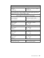
Force power-off states . . . . . . . . . . . . . . . . . . . . . . . . . . . . . . . . . . . . . . . . . . . . . . . . . . . . . . . .
Power-off states . . . . . . . . . . . . . . . . . . . . . . . . . . . . . . . . . . . . . . . . . . . . . . . . . . . . . . . . . . . . . .
Dump states . . . . . . . . . . . . . . . . . . . . . . . . . . . . . . . . . . . . . . . . . . . . . . . . . . . . . . . . . . . . . . . . .
Reset states . . . . . . . . . . . . . . . . . . . . . . . . . . . . . . . . . . . . . . . . . . . . . . . . . . . . . . . . . . . . . . . . .
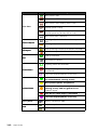
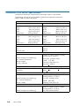
Domain functional status indicators . . . . . . . . . . . . . . . . . . . . . . . . . . . . . . . . . . . . . . . . . . . . .
Domain hardware details icons . . . . . . . . . . . . . . . . . . . . . . . . . . . . . . . . . . . . . . . . . . . . . . . .
Domain power sequence error messages . . . . . . . . . . . . . . . . . . . . . . . . . . . . . . . . . . . . . . . .
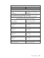
CSS hardware functional status icons . . . . . . . . . . . . . . . . . . . . . . . . . . . . . . . . . . . . . . . . . . .
Hardware presence status indicators . . . . . . . . . . . . . . . . . . . . . . . . . . . . . . . . . . . . . . . . . . .
Hardware functional status indicators . . . . . . . . . . . . . . . . . . . . . . . . . . . . . . . . . . . . . . . . . . .
Fault status indicators . . . . . . . . . . . . . . . . . . . . . . . . . . . . . . . . . . . . . . . . . . . . . . . . . . . . . . . . .
Power tab status indicators . . . . . . . . . . . . . . . . . . . . . . . . . . . . . . . . . . . . . . . . . . . . . . . . . . . .
Temperature tab status indicators . . . . . . . . . . . . . . . . . . . . . . . . . . . . . . . . . . . . . . . . . . . . . . .
Hardware exclusion guidelines - 1 . . . . . . . . . . . . . . . . . . . . . . . . . . . . . . . . . . . . . . . . . . . . .
Hardware exclusion guidelines . . . . . . . . . . . . . . . . . . . . . . . . . . . . . . . . . . . . . . . . . . . . . . . .
Message severity levels . . . . . . . . . . . . . . . . . . . . . . . . . . . . . . . . . . . . . . . . . . . . . . . . . . . . . . .
CSS functional status / domain state . . . . . . . . . . . . . . . . . . . . . . . . . . . . . . . . . . . . . . . . . . .
NovaScale SMP server domain cell resources . . . . . . . . . . . . . . . . . . . . . . . . . . . . . . . . . . . .
NovaScale partitioned server domain cell resources . . . . . . . . . . . . . . . . . . . . . . . . . . . . . .
Boot Option Maintenance Menu . . . . . . . . . . . . . . . . . . . . . . . . . . . . . . . . . . . . . . . . . . . . . . .
Wildcard character expansion . . . . . . . . . . . . . . . . . . . . . . . . . . . . . . . . . . . . . . . . . . . . . . . . .
Output redirection syntax . . . . . . . . . . . . . . . . . . . . . . . . . . . . . . . . . . . . . . . . . . . . . . . . . . . . .
List of EFI Shell Commands . . . . . . . . . . . . . . . . . . . . . . . . . . . . . . . . . . . . . . . . . . . . . . . . . . . .
User access to PAM features . . . . . . . . . . . . . . . . . . . . . . . . . . . . . . . . . . . . . . . . . . . . . . . . . . .
Domain configuration assessment criteria - 1 . . . . . . . . . . . . . . . . . . . . . . . . . . . . . . . . . . . . .
Domain configuration assessment criteria - 2 . . . . . . . . . . . . . . . . . . . . . . . . . . . . . . . . . . . . .
Hardware locking options . . . . . . . . . . . . . . . . . . . . . . . . . . . . . . . . . . . . . . . . . . . . . . . . . . . . .
Scheme configuration criteria - example 1 - mono-module server . . . . . . . . . . . . . . . . . . .
Scheme configuration criteria - example 1 - 2 modules server . . . . . . . . . . . . . . . . . . . . . .
Scheme configuration criteria - example 1 - 3 modules server . . . . . . . . . . . . . . . . . . . . . .
Scheme configuration criteria - example 1 - 4 modules server . . . . . . . . . . . . . . . . . . . . . .
Scheme configuration criteria - example 2 - mono-module server . . . . . . . . . . . . . . . . . . .
Scheme configuration criteria - example 2 - bi-module server . . . . . . . . . . . . . . . . . . . . . . .
Scheme configuration criteria - example 2 - 3 modules server . . . . . . . . . . . . . . . . . . . . . .
Scheme configuration criteria - example 2 - 4 modules server . . . . . . . . . . . . . . . . . . . . . .
Scheme configuration criteria - example 3 - mono-module server . . . . . . . . . . . . . . . . . . .
Preface
xv
xx
xxi
2-7
2-9
3-4
3-13
3-15
3-17
3-18
3-20
3-22
3-23
3-24
3-25
3-30
3-40
3-42
4-4
4-6
4-8
4-16
4-18
4-20
4-25
4-26
4-32
4-43
4-44
4-45
5-8
5-10
5-10
5-13
5-18
5-31
5-32
5-66
5-69
5-70
5-71
5-72
5-83
5-84
5-85
5-86
5-97
Table
Table
Table
Table
Table
Table
Table
Table
Table
Table
Table
Table
Table
Table
Table
Table
Table
Table
Table
Table
Table
Table
47.
48.
49.
50.
51.
52.
53.
54.
55.
56.
57.
58.
59.
60.
61.
62.
63.
64.
65.
66.
67.
68.
Scheme configuration criteria - example 3 - bi-module server . . . . . . . . . . . . . . . . . . . . . . .
Scheme configuration criteria - example 3 - 3 modules server . . . . . . . . . . . . . . . . . . . . . .
Scheme configuration criteria - example 3 - 4 modules server . . . . . . . . . . . . . . . . . . . . . .
Scheme configuration criteria - example 4 - bi-module server . . . . . . . . . . . . . . . . . . . . . . .
Scheme configuration criteria - example 4 - 3 modules server . . . . . . . . . . . . . . . . . . . . . .
Scheme configuration criteria - example 4 - 4 modules server . . . . . . . . . . . . . . . . . . . . . .
Scheme configuration checklist . . . . . . . . . . . . . . . . . . . . . . . . . . . . . . . . . . . . . . . . . . . . . . . . .
Domain Identity configuration checklist . . . . . . . . . . . . . . . . . . . . . . . . . . . . . . . . . . . . . . . . . .
Resources checklist - part 1 . . . . . . . . . . . . . . . . . . . . . . . . . . . . . . . . . . . . . . . . . . . . . . . . . . . .
Resources checklist - part 2 . . . . . . . . . . . . . . . . . . . . . . . . . . . . . . . . . . . . . . . . . . . . . . . . . . . .
Resources checklist - part 3 . . . . . . . . . . . . . . . . . . . . . . . . . . . . . . . . . . . . . . . . . . . . . . . . . . . .
Resources checklist - part 4 . . . . . . . . . . . . . . . . . . . . . . . . . . . . . . . . . . . . . . . . . . . . . . . . . . . .
Event channels . . . . . . . . . . . . . . . . . . . . . . . . . . . . . . . . . . . . . . . . . . . . . . . . . . . . . . . . . . . . . .
Event channel selection guidelines . . . . . . . . . . . . . . . . . . . . . . . . . . . . . . . . . . . . . . . . . . . . . .
Standard event message filtering criteria . . . . . . . . . . . . . . . . . . . . . . . . . . . . . . . . . . . . . . . .
Advanced event message filtering criteria . . . . . . . . . . . . . . . . . . . . . . . . . . . . . . . . . . . . . . .
System history contents . . . . . . . . . . . . . . . . . . . . . . . . . . . . . . . . . . . . . . . . . . . . . . . . . . . . . . .
History automatic achiving policies . . . . . . . . . . . . . . . . . . . . . . . . . . . . . . . . . . . . . . . . . . . . .
NovaScale 5085 Server specifications . . . . . . . . . . . . . . . . . . . . . . . . . . . . . . . . . . . . . . . . . .
NovaScale 5165 Server specifications . . . . . . . . . . . . . . . . . . . . . . . . . . . . . . . . . . . . . . . . . .
NovaScale 5245 Server specifications . . . . . . . . . . . . . . . . . . . . . . . . . . . . . . . . . . . . . . . . . .
NovaScale 5325 Server specifications . . . . . . . . . . . . . . . . . . . . . . . . . . . . . . . . . . . . . . . . . .
xvi User's Guide
5-98
5-99
5-100
5-112
5-113
5-114
5-126
5-127
5-128
5-129
5-130
5-131
5-134
5-140
5-147
5-152
5-156
5-158
A-3
A-5
A-7
A-9
Intended Readers
This guide is intended for use by the Administrators and Operators of NovaScale 5xx5
Servers.
It will also prove useful to the Administrators and Operators of Bull NovaScale 7000 Series
and Bull NovaScale 9000 Series servers.
Chapter 1. Introducing the Server
describes server hardware components and user environment.
Chapter 2. Getting Started
explains how to connect to and use the server.
Chapter 3. Managing Domains
describes how to perform straightforward server domain management tasks.
Chapter 4. Monitoring the Server
explains how to supervise server operation.
Chapter 5. Tips and Features for Administrators
explains how, as Customer Administrator, you can configure the server to suit your
environment.
Appendix A. Specifications
Highlighting
The following highlighting conventions are used in this guide:
Bold
Identifies predefined commands, subroutines, keywords, files,
structures, buttons, labels, and icons.
Italics
Identifies referenced publications, chapters, sections, figures,
and tables.
<
>
Identifies parameters to be supplied by the user.
Abbreviations, acronyms and concepts are documented in the Glossary.
Related Publications
Site Preparation Guide, 86 A1 87EF
explains how to prepare a Data Processing Center for Bull NovaScale Servers, in
compliance with the standards in force. This guide is intended for use by all personnel
and trade representatives involved in the site preparation process.
Installation Guide, 86 A1 40EM
explains how to set up and start NovaScale 5xx5 Servers for the first time. This guide is
intended for use by qualified support personnel.
Cabling Guide, 86 A192ER
describes server cabling.
Bull 1300H/L & 1100H/L Cabinets, 86 A1 91EM
explains how to install and fit out rack cabinets for Bull NovaScale Servers and peripheral
devices.
Note:
According to server configuration and version, certain features and functions described in
this guide may not be accessible. Please contact your Bull Sales Representative for sales
information.
Preface
xvii
Regulatory Specifications and Disclaimers
Declaration of the Manufacturer or Importer
We hereby certify that this product is in compliance with European Union EMC Directive
2004/108/CE, using standards EN55022 (Class A) and EN55024 and Low Voltage
Directive 2006/95/CE, using standard EN60950. The product has been marked with the
CE Mark to illustrate its compliance.
Safety Compliance Statement
• UL 60950 (USA)
• IEC 60950 (International)
• CSA 60950 (Canada)
European Community (EC) Council Directives
This product is in conformity with the protection requirements of the following EC Council
Directives:
Electromagnetic Compatibility
• 2004/108/CE
Low Voltage
• 2006/95/CE
EC Conformity
• 93/68/EEC
Telecommunications Terminal Equipment
• 1999/5/EC
Neither the provider nor the manufacturer can accept responsibility for any failure to satisfy
the protection requirements resulting from a non-recommended modification of the product.
Compliance with these directives requires:
• an EC declaration of conformity from the manufacturer
• an EC label on the product
• technical documentation
xviiiUser's Guide
Federal Communications Commission (FCC) Statement
Note:
This equipment has been tested and found to comply with the limits for a Class A digital
device, pursuant to Part 15 of the FCC Rules. These limits are designed to provide
reasonable protection against harmful interference when the equipment is operated in a
commercial environment. This equipment generates, uses, and can radiate radio frequency
energy and, if not installed and used in accordance with the instruction manual, may cause
harmful interference to radio communications. Operation of this equipment in a residential
area is likely to cause harmful interference in which case the user will be required to correct
the interference at his own expense.
Properly shielded and grounded cables and connectors must be used in order to meet FCC
emission limits. Neither the provider nor the manufacturer are responsible for any radio or
television interference caused by using other than recommended cables and connectors or by
unauthorized changes or modifications to this equipment. Unauthorized changes or
modifications could void the user's authority to operate the equipment.
Any changes or modifications not expressly approved by the grantee of this device could
void the user's authority to operate the equipment. The customer is responsible for ensuring
compliance of the modified product.
FCC Declaration of Conformity
This device complies with Part 15 of the FCC Rules. Operation is subject to the following two
conditions: (1) this device may not cause harmful interference, and (2) this device must
accept any interference received, including interference that may cause undesired operation.
Canadian Compliance Statement (Industry Canada)
This Class A digital apparatus meets all requirements of the Canadian Interference Causing
Equipment Regulations.
Cet appareil numérique de la classe A est conforme à la norme NMB-003 du Canada.
This product is in conformity with the protection requirements of the following standards:
Electromagnetic Compatibility
• ICES-003
• NMB-003
Laser Compliance Notice
This product that uses laser technology complies with Class 1 laser requirements.
A CLASS 1 LASER PRODUCT label is located on the laser device.
Class 1 Laser Product
Luokan 1 Laserlaite
Klasse 1 Laser Apparat
Laser Klasse 1
Preface
xix
Definition of Safety Notices
DANGER
A Danger notice indicates the presence of a hazard that has the potential of causing death or
serious personal injury.
CAUTION:
A Caution notice indicates the presence of a hazard that has the potential of causing
moderate or minor personal injury.
Warning:
A Warning notice indicates an action that could cause damage to a program, device, system,
or data.
Electrical Safety
The following safety instructions shall be observed when connecting or disconnecting devices
to the system.
DANGER
The Customer is responsible for ensuring that the AC electricity supply is compliant with
national and local recommendations, regulations, standards and codes of practice.
An incorrectly wired and grounded electrical outlet may place hazardous voltage on metal
parts of the system or the devices that attach to the system and result in an electrical shock.
It is mandatory to remove power cables from electrical outlets before relocating the system.
CAUTION:
This unit has more than one power supply cable. Follow procedures for removal of power
from the system when directed.
xx User's Guide
Laser Safety Information
The optical drive in this system unit is classified as a Class 1 level Laser product. The optical
drive has a label that identifies its classification.
The optical drive in this system unit is certified in the U.S. to conform to the requirements of
the Department of Health and Human Services 21 Code of Federal Regulations (DHHS 21
CFR) Subchapter J for Class 1 laser products. Elsewhere, the drive is certified to conform to
the requirements of the International Electrotechnical Commission (IEC) 60825-1: 2001 and
CENELEC EN 60825-1: 1994 for Class 1 laser products.
CAUTION:
Invisible laser radiation when open. Do not stare into beam or view directly with optical
instruments.
Class 1 Laser products are not considered to be hazardous. The optical drive contains
internally a Class 3B gallium-arsenide laser that is nominally 30 milliwatts at 830
nanometers. The design incorporates a combination of enclosures, electronics, and
redundant interlocks such that there is no exposure to laser radiation above a Class 1 level
during normal operation, user maintenance, or servicing conditions.
Data Integrity and Verification
Warning:
Bull NovaScale Servers are designed to reduce the risk of undetected data corruption or loss.
However, if unplanned outages or system failures occur, users are strongly advised to check
the accuracy of the operations performed and the data saved or transmitted by the system at
the time of outage or failure.
Waste Management
This product has been built to comply with the Restriction of Certain Hazardous Substances
(RoHS) Directive 2002/95/EC.
This product has been built to comply with the Waste Electrical and Electronic (WEEE)
Directive 2002/96/EC.
Preface
xxi
PAM Writing Rules
Illegal Characters
The following table lists the illegal characters that must not be used in PAM identifiers.
Illegal Characters
à, é, è, ù, ^, ¨
Accentuated letters
/
Slash
\
Backslash
"
Double quote
'
Simple quote
`
Inverted comma
&
Ampersand
+
Plus
*
Asterisk
%
Percent
=
Equal sign
<
Less-than sign
>
Greater-than sign
:
Colon
!
Exclamation mark
?
Question mark
;
Semi-colon
,
Comma
~
Tilde
I
Pipe operator
Space. Use - (dash) or _ (underscore)
Table 1.
xxii User's Guide
PAM illegal characters
String Lengths
The following table lists authorized string lengths.
String Type
CellBlock / System Name
Scheme Name
History Name
Archive Name
LUN Name
Switch Name
Event Name
Description
Domain Identity Name
Table 2.
Length
16
32
64
75 (History Name: + 11
(_JJMMAA_nnn)
32
32
32
256 (Scheme: unlimited)
16
String length rules
Registry Keys
PAM obtains file paths via 2 registry keys:
• ReleaseRoot:
Contains PAP application file paths (DLL, WEB pages, models,...).
Two versions of PAM software can be installed and used indifferently on the same
machine: each new version is installed in a new directory.
• SiteRoot:
Contains site data file paths.
Site data remains valid when the PAM software version changes.
Registry keys are generally stored under: HKEY_LOCAL_MACHINE\SOFTWARE\BULL\PAM
Preface
xxiii
AZERTY/QWERTY Keyboard Lookup Table
Figure 1.
AZERTY keyboard
Figure 2.
QWERTY keyboard
xxivUser's Guide
Administrator's Memorandum
Domains
• Manage Domain Schemes, on page 3-5
• Synchronize NovaScale 5xx5 SMP Server Domains, on page 3-6
• Power ON a Domain, on page 3-14
• Power OFF a Domain, on page 3-18
• Perform a Manual Domain Reset, on page 3-25
• Perform a Domain Force Power OFF, on page 3-21
• Perform a Domain Memory Dump, on page 3-24
• View Domain Functional Status, on page 3-29
• View Domain Power Logs, on page 3-31
• View Domain Powering Sequences, on page 3-32
• View Domain BIOS Info, on page 3-33
• View Domain Request Logs, on page 3-34
• View Domain Configuration, Resources and Status, on page 3-35
• Solve Incidents, on page 3-42
* Reserved for partitioned servers and extended systems.
Monitoring
• Refresh the PAM Display, on page 4-2
• View CSS Availability Status and System Functional Status, on page 4-4
• View Event Message Status, on page 4-4
• Display Hardware Presence / Functional Status, on page 4-5
• View PAM Web Site User Information, on page 4-12
• View PAM Version Information, on page 4-13
• View Server Hardware Status, on page 4-14
• Use the Hardware Search Engine, on page 4-10
• Display Detailed Hardware Information, on page 4-15
• Exclude / Include Hardware Elements, on page 4-23
• Exclude / Include Clocks, SPS, XSP Links and Sidebands, on page 4-27
• Manage PAM Event Messages, History Files, Archives, Fault Lists, on page 4-31
• Understand Message Severity Levels, on page 4-32
• View, Acknowledge WEB Event Messages, on page 4-34
• Sort and Locate Messages, on page 4-35
• Solve Incidents, on page 4-42
• Create an Action Request Package, on page 4-51
• Create a Custom Package, on page 4-54
Preface
xxv
Configuration
• Set up Server Users, on page 5-4
• Configure System and Data Disks, on page 5-5
• Use the EFI Boot Manager, on page 5-7
• Use the EFI Shell, on page 5-9
• Set Up and Configure the EFI Network, on page 5-14
• Set up PAP Unit Users, on page 5-17
• Modify Customer Information, on page 5-17
• Configure PAM Autocall Parameters, on page 5-20
• Customize PAM Settings, on page 5-22
• Deploy a New PAM Release, on page 5-23
• Activate a PAM Version, on page 5-24
• Back Up and Restore PAM Configuration Files, on page 5-26
• Configure Domains, on page 5-28*
• Assess Configuration Requirements, on page 5-31*
• Create, Edit, Copy, Delete, Rename a Domain Scheme, on page 5-33*
• Update DefaultSchemes, on page 5-49*
• Create, Edit, Copy, Delete a Domain Identity, on page 5-50*
• Manage LUNs (Servers Not Connected to a SAN), on page 5-57
• Manage LUNs (Servers Connected to a SAN), on page 5-55
• Check and Update Fibre Channel HBA World Wide Names, on page 5-64
• Limit Access to Hardware Resources, on page 5-66
• Configure Extended Systems, on page 5-125*
• Prepare Scheme, Domain Identity and Resources Checklists, on page 5-126*
• Customize the PAM Event Messaging System, on page 5-133
• Set up Event Subscriptions, on page 5-134
• Event Subscription Flowcharts, on page 5-134
• Create, Edit, Delete an E-mail Server, on page 5-136
• Create, Edit, Delete an E-mail Account, on page 5-138
• Create, Edit, Delete a User History, on page 5-157
• Enable / Disable Event Channels, on page 5-140
• Create, Edit, Delete an Event Subscription, on page 5-141
• Understand Event Message Filtering Criteria, on page 5-143
• Preselect an Event Filter, on page 5-153
• Create, Edit, Delet an Event Filter, on page 5-154
• Excluding / Including Clocks, SPS, XSP Links and Sidebands, on page 4-27
* Reserved for partitioned servers and extended systems.
xxviUser's Guide
Operator's Memorandum
Domains
• Synchronize NovaScale 5xx5 SMP Server Domains, on page 3-6
• Power ON a Domain, on page 3-14
• Power OFF a Domain, on page 3-18
• Perform a Domain Force Power OFF, on page 3-21
• Perform a Manual Domain Reset, on page 3-25
• Perform a Domain Memory Dump, on page 3-24
• View Domain Functional Status, on page 3-29
• View Power Logs, on page 3-31
• View Domain Powering Sequences, on page 3-32
• View BIOS Info, on page 3-33
• View Domain Request Logs, on page 3-34
• View Domain Configuration, Resources and Status, on page 3-35
• Solve Incidents, on page 3-42
Histories
• Manage PAM Event Messages, History Files, Archives, Fault Lists, on page 4-31
• Understand Event Message and History Severity Levels, on page 4-32
• Sort and Locate messages, on page 4-35
Status
• Check System Functional Status, on page 4-4
• Check CSS Availability, on page 4-4
• View, Acknowledge WEB Event Messages, on page 4-34
• Sort, Locate WEB event messages, on page 4-35
Prefacexxvii
xxviii
User's Guide
Chapter 1. Introducing the Server
This chapter describes the main hardware components and user environment for NovaScale
5xx5 Servers. It includes the following topics:
• Bull NovaScale Server Overview, on page 1-2
• Accessing Server Components, on page 1-20
• Bull NovaScale Server Resources, on page 1-22
• PAM Software Package, on page 1-22
• EFI Utilities, on page 1-23
Note:
Customer Administrators and Customer Operators are respectively advised to consult the
Administrator's Memorandum, on page xxv or the Operator's Memorandum, on page xxvii
for a detailed summary of the everyday tasks they will perform.
Introducing the Server
1-1
Bull Novascale Server Overview
Bull NovaScale Servers for business and scientific applications are based upon the FAME
architecture (Flexible Architecture for Multiple Environments), leveraging the latest generation
of Intel Itanium 2 processors.
Servers are designed to operate as one to eight hardware-independent SMP systems or
domains, each running an Operating System instance and a specific set of applications.
According to version, servers are delivered rack-mounted and ready-to-use in high or low
cabinets.
Figure 3.
Bull NovaScale Server cabinets
Dynamic Partitioning
Bull NovaScale Servers can be dynamically partitioned into physically independent ccNUMA
(Cache Coherent Non Uniform Memory Access) SMP systems or domains, each running an
Operating System instance and a specific set of applications.
Extended Configurations
Several Bull NovaScale Servers may be administered through a single instance of PAM
software.
Cluster Configurations
Several Bull NovaScale Servers may be grouped to act like a single system, enabling high
availability, load balancing and parallel processing.
1-2
User's Guide
Server Features
The main features of Bull NovaScale Servers are:
Intel Itanium Processor Family architecture:
- Modularity, predictable performance and growth
High availability:
- Component redundancy
-
Capacity to isolate or replace a faulty component without service disruption
-
Global and unified system visibility
-
Round-the-clock operation
Scalability:
- Dynamic partitioning
-
Power on demand: capacity to dynamically adapt resources and processor frequency
to load requirement
Simultaneous support of multiple environments:
- Microsoft Windows
Server
-
Linux
High performance computing capabilites:
- Technical and scientific applications:
. High Performance Computing (HPC)
-
Business Intelligence:
. Datawarehousing
. Datamining
-
Large enterprise applications:
. ERP
. CRM
. SCM ...
-
Large database applications for Internet transactions.
-
Large business sector applications:
. Online billing
. Online reservations
. Online banking ...
Built-in Platform Administration and Maintenance (PAM) software suite:
- Proactive administration
-
Optimization of resources
-
Automatic generation of corrective actions and calls to support centers
-
Dynamic configuration
Bull NovaScale Master System Management (NSM) software suite:
- Windows, Linux, and Platform management
-
Monitoring, Information, Control, and Event Handling
-
Client / Server / Agent architecture
-
WEB standard OpenSource solutions
Introducing the Server
1-3
Server Hardware
Note:
Abbreviations and acronyms are documented in the Glossary.
Main server hardware components are:
Central SubSystem Module (CSS Module)
Main server hardware components are housed in the CSS Module. For easy access and
servicing, the CSS Module is composed of three interconnected units:
Front Unit
Core Unit
Rear Unit
1 or 2QBBs
1 MQB
1 or 2 IOCs
1 or 2 Internal Peripheral Drawers
1 MIO
1 or 2 IOLs
2 MSXs
1 PMB
1 MFL
2 or 4 DPS Units
8 Fanboxes
Notes:
• The CSS Module can be logically divided into two Cells, each with one QBB and one
IOC, to allow dynamic partitioning.
• According to version, servers are equipped with one, two, three, or four interconnected
CSS modules.
Front Unit
Quad Brick Block (QBB)
The QBB is equipped with 2 to 4 Itanium 2 processors and 16 DDR DIMMs. The QBB
communicates with the rest of the system the high-speed bidirectional link Scalability Port
Switches (SPS) located on the MSX.
Internal Peripheral Drawer (IPD)
The Internal Peripheral Drawer is equipped with a DVD/CD ROM drive and a USB port. The
Internal Peripheral Drawer is connected to the MQB in the Core Unit via a Device Interface
Board (DIB).
Optionally:
• the Internal Peripheral Drawer can house 2 SCSI Disks for OS partitions or storage,
• two Internal Peripheral Drawers, in the same CSS module, can be connected together to
house 4 SCSI Disks for OS partitions or storage (Chained DIBs).
Core Unit
Midplane QBB Board (MQB)
The QBBs and the Internal Peripheral Drawers are connected to the MQB.
Midplane IO Board (MIO)
The IOCs and the PMB are connected to the MIO.
Midplane SPS & XPS Board (MSX)
Each MSX houses 1 high-speed directional link Scalability Port Switch (SPS) and is connected
to both the MIO and the MQB. Each QBB and IOC communicates with the rest of the system
through the SPS.
1-4
User's Guide
Midplane Fan & Logistics Board (MFL)
16 Fans and various logistics components are implemented on the MFL. The MFL is
connected to both the MIO and the MQB.
Fanboxes
8 Fanboxes, each housing 2 fans, provide redundant cooling.
Rear Unit
IO board Compact (IOC)
The IOC provides 4 x PCI -X and 2 x PCI-Express buses and a PCI Hot Plug Board (HPB).
The IOC communicates with the rest of the system through the high-speed bidirectional link
Scalability Port Switches (SPS) located on the MSX.
IO board Legacy (IOL)
The IOL is an IOC daughter board providing legacy IO connections: 2 USB ports, 1 LAN
port, 2 serial ports, and 1 video port.
Platform Maintenance Board (PMB)
The PMB concentrates logistics access and links the platform to the Platform Administration
Processor (PAP Unit) running Platform Administration and Maintenance (PAM) software.
Distributed Power Supply (DPS) Unit
Each DPS Unit supplies 48V AC/DC power to the server. The server is equipped with 2 or 4
DPS units for full redundancy.
Platform Administration Processor (PAP) Unit
The PAP Unit hosts all server administration software, in particular Platform Administration
and Maintenance (PAM) software.
KVM Switch
The KVM Switch allows the use of a single keyboard, monitor and mouse for the local server
domains and the local PAM console.
Console
The Console contains the keyboard, monitor and touch pad / mouse used for local access to
the server domains and to the PAP Unit.
Disk Subsystem
If the disk slots in the Internal Peripheral Drawer are not used for OS disk partitions, a SCSI
RAID or FC disk subsystem is required.
Additional Peripherals
Additional peripherals such as disk subsystems, storage area networks, communication
networks, archiving peripherals etc. can be connected to the server via PCI adapters located
in the IOCs. Such peripherals may either be rack-mounted in the server cabinet (if free space
is available) or in external cabinets.
Server Firmware and Software
Operating Systems (OS)
The server is certified for the following Operating Systems:
• Windows Server 2003, Enterprise Edition
• Windows Server 2003, Datacenter Edition
• Linux Red Hat Enterprise Linux Advanced Server
• Novell SUSE SLES 9
Introducing the Server
1-5
BIOS
The BIOS controls the server startup process, dynamic resource allocation (Domain
reconfiguration, hot-plugging), and error handling. The BIOS also includes:
• The Extended Firmware Interface (EFI), which provides the OS with system services.
• The EFI Shell, an autonomous environment used to run Off-line Test & Diagnostic suites.
Platform Administration and Maintenance (PAM) suite
The PAM Web-based software suite is used to operate, monitor, and configure the server.
PAM can be accessed locally or remotely through Microsoft Internet Explorer or Mozilla
browsers, under the protection of appropriate access rights. PAM provides the administration
functions needed to manage and maintain the server:
• Domain configuration and resource allocation
• Alert or maintenance requests to the Customer Service Center
• Error logging …
Test & Diagnostics suites
The server is delivered with the following T & D suites:
• Online Test & Diagnostic suite
• Offline Test & Diagnostic suite
• Power-On Self-Test suite
NovaScale Master (NSM) Management suite
The NSM software suite allows you to monitor and manage NovaScale Windows and Linux
systems.
Conformance to Standards
Intel
Bull NovaScale Servers conform to all Intel platform standards:
• ACPI (Advanced Configuration and Power Interface)
• IPMI (Intelligent Platform Management Interface)
• EFI (Extended Firmware Interface)
• SMBIOS (System Management BIOS)
• DIG64 (Developer Interface Guide for Intel Itanium Architecture)
Windows
Bull NovaScale Servers conform to the standards set out in the Windows Hardware Design
Guide.
1-6
User's Guide
Getting to Know the Server
NovaScale 5085 Partitioned Server
Note:
Server components and configuration may differ according to the version chosen.
The server is delivered rack-mounted and pre-cabled in a low or high cabinet, typically
containing the following components:
XXXXXXXX
1
Front
XXXXXXXXXXXXXXXXXXXX
Rear
CSS module with core unit, power supply and AC power cable, including:
2xIO Boxes (IOC) each with:
2xInternal Peripheral Drawers each with:
2
IOL board - legacy ports
3
4xPCI-X & 2x PCI-Express slots
4
DVD-ROM drive
5
2xInternal SCSI RAID disks
6
USB port
PMB board
7
2 or 4 DPS units
8
2xQBB subsets (1 to 4 CPUs each)
*Multicore CPU = Socket
9
8U
10* Slideaway console with monitor and keyboard
1U
11
8-ports KVM switch
1U
1U
12
PAP unit with CD-ROM writer, FDD and 2 disks
13*
*
1 or 2 PDU(s) with AC power cable
14
1 optional FC disk
3U
16
Free space for additional components
4U
*
**
Figure 4.
Slideaway console. For an external console, use a KVM extender kit (150m max.).
Redundant servers are connected to 2 PDUs and have 4 DPS units.
NovaScale 5085 Partitioned Server components - example
Introducing the Server
1-7
NovaScale 5165 Partitioned Server
Note:
Server components and configuration may differ according to the version chosen.
The server is delivered rack-mounted and pre-cabled in a high cabinet, typically containing
the following components:
XXXXXXXX
1,
15
10*
11
12
13**
14
16
User's Guide
XXXXXXXXXXXXXXXXXXXX
Rear
8Ux
2
1U
1U
1U
3Ux
2
Free space for additional components (SCSI or FC disks)
14 U
*
Slideaway console. For an external console, use a KVM extender kit (150m max.).
** Redundant servers are connected to 2 PDUs and have 4 DPS units.
Figure 5.
1-8
Front
CSS module with core unit, power supply and AC power cable, including:
2
IOL board - legacy ports
IO Box (IOC) with:
3
4xPCI-X & 2x PCI-Express slots
4
DVD-ROM drive
Internal Peripheral Drawer with:
5
2xInternal SCSI RAID disks
6
USB port
PMB board
7
2 or 4 DPS units
8
2xQBB subsets (1 to 4 CPUs each)
9
*Multicore CPU = Socket
Slideaway console with monitor and keyboard
8-ports KVM switch
PAP unit with CD-ROM writer, FDD and 2 disks
1 or 2 PDU(s) with AC power cable
2 FC disks (optional)
NovaScale 5165 Partitioned Server components - example
NovaScale 5245 Partitioned Server
Note:
Server components and configuration may differ according to the version chosen.
The server is delivered rack-mounted and pre-cabled in a high cabinet, typically containing
the following components:
XXXXXXXX
1,
15,
16
10*
11
12
13**
14
16
18
Front
XXXXXXXXXXXXXXXXXXXX
Rear
CSS module with core unit, power supply and AC power cable, including:
2
IOL board - legacy ports
IO Box (IOC) with:
3
4xPCI-X & 2x PCI-Express slots
4
DVD-ROM drive
Internal Peripheral Drawer with:
5
2xInternal SCSI RAID disks
6
USB port
PMB board
7
2 or 4 DPS units
8
2xQBB subsets (1 to 4 CPUs each)
9
*Multicore CPU = Socket
External console with monitor and keyboard
8-ports KVM switch
PAP unit with CD-ROM writer, FDD and 2 disks
1 or 2 PDU(s) with AC power cable
2 FC disks
Free space for additional components (SCSI or FC disks)
KVM extender
* External console, use a KVM extender kit (150m max.).
** Redundant servers are connected to 2 PDUs and have 4 DPS units.
Figure 6.
8Ux
3
1U
1U
3 U x2
14 U
1U
NovaScale 5245 Partitioned Server components - example
Introducing the Server
1-9
NovaScale 5325 Partitioned Server
Note:
Server components and configuration may differ according to the version chosen.
The server is delivered rack-mounted and pre-cabled in two high cabinets, typically
containing the following components:
Main Cabinet
XXXXXXXX
1,
15,
16,
17
11
13*
18
User's Guide
XXXXXXXXXXXXXXXXXXXX
Rear
2 or 4 PDU(s) with AC power cable
KVM extender (local)
*
Redundant servers are connected to 2 PDUs and have 4 DPS units.
Figure 7.
1-10
Front
CSS module with core unit, power supply and AC power cable, including:
2
IOL board - legacy ports
IO Box (IOC) with:
3
4xPCI-X & 2x PCI-Express slots
4
DVD-ROM drive
Internal Peripheral Drawer with:
5
2xInternal SCSI RAID disks
6
USB port
PMB board
7
2 or 4 DPS units
8
2xQBB subsets (1 to 4 CPUs each)
9
*Multicore CPU = Socket
2 x 8-ports KVM switch
NovaScale 5325 Partitioned Servers components - example
8Ux
4
1Ux
2
1U
I/O Cabinet
10
PAP unit with CD-ROM writer, FDD and 2 disks
13
2 PDU(s) with AC power cable
14
2 FC disks
18
KVM extender (remote)
Figure 8.
1U
3x2 U
1U
NovaScale 5325 Partitioned Servers components - example
Introducing the Server
1-11
Server Components
Note:
Server components and configuration may differ according to the version chosen.
The server includes the following components:
• CSS module, on page 1-13
• Integrated console, on page 1-15
• Integrated Platform Administration Processor (PAP) unit, on page 1-14
• Keyboard / Video / Mouse (KVM) switch, on page 1-16
• Fibre Channel (FC) disks, on page 1-17
• Ethernet hub, on page 1-19
• USB modem, on page 1-19
• NPort server, on page 1-19
1-12
User's Guide
Central Subsystem (CSS) Module
The CSS module houses main hardware components:
Front
Rear
Front 1 or 2 QBB (Quad Brick Board) subset(s):
Each QBB subset houses:
• 1 mother board
• 2 memory boards
• 1 to 4 processors
• 16 DIMMs
1 or 2 Internal Peripheral Drawer(s):
Each drawer houses:
• 2 internal SCSI RAID system disks
• 1 DVD-ROM drive
• 1 USB port
Chaine d DIBs:
Two Internal Peripheral Drawers can be inter-connected to house:
• 4 SCSI RAID disks, 1 DVD-ROM drive, 1 USB port
Rear
1 or 2 IO Box(es) (Input / Output Board Compact):
Each IO Box can house:
• 1 HPB (PCI Hot Plug Board)
• 6 hot-plug 133 MHz PCI-X and PCI Xpress slots (2 long, 4 short)
• 1 IOL (Input / Output board Legacy):
- 2 A-type USB ports
- 1 RJ45 10/100/1000 Mbps Ethernet port
- 2 DB9-M RS232 serial ports
- 1 HD15-F VGA port
1 PMB (Platform Management Board):
This active board links the server to the Platform Administration Processor (PAP) Unit
(via an Ethernet link).
Core
1 Core unit
This set of 5 active boards is used to interconnect the QBBs, IOCs, DIBs and the
PMB.
Figure 9.
CSS module features (full CSS module example)
Introducing the Server
1-13
Integrated Platform Administration Processor (PAP) Unit
Warning:
The PAP unit has been specially configured for Bull NovaScale Server administration and
maintenance. NEVER use the PAP unit for other purposes and NEVER change PAP unit
configuration unless instructed to do so by an authorized Customer Service Engineer.
The PAP unit is linked to the server via the Platform Management Board (PMB). It hosts
Platform Administration Software (PAM). According to version, the PAP unit is located in the
center of a high cabinet or at the top of a low cabinet.
PAP Unit 1U
• 1 P4C / 3 GHz PC
-
1 GB RAM
-
2 x 80 GB SATA disks (RAID1)
-
1 CD/DVD-ROM drive
-
1 1 FDD
-
2 serial ports
-
1 parallel port
-
3 PCI slots
-
2 Gigabit Ethernet ports (1 free)
-
3 USB 2.0 ports (1 front + 2 rear)
-
1 SVGA video port
-
2 PS/2 ports
• Microsoft Windows operating system
• Internet Explorer software
• PAM software
• 1 power cable
Figure 10. PAP unit
1-14
User's Guide
Integrated Console
According to version, the console is located in the center of a high cabinet or at the top of a
low cabinet.
The inegrated console contains the keyboard, monitor and touch pad used for local access to
the server and to the Platform Administration Processor (PAP) Unit.
or
• 1 monitor
• 1 QWERTY keyboard and touch pad
• 1 power cable
Figure 11. Integrated console features
Introducing the Server
1-15
Keyboard / Video / Mouse (KVM) Switch
The KVM Switch allows the use of the integrated console for the local server and the local
Platform Administration and Maintenance console.
8-Port KVM Switch
Or
Or
• 8 ports
• 1 power cable
Figure 12. 8-port KVM switch features
16-Port KVM Switch
• 16 ports
• 1 power cable
Figure 13. 16-port KVM switch features
KVM Extender
Figure 14. KVM extender (local & remote) 300m maxi.
1-16
User's Guide
FDA 1x00 FC Disk Rack
Optionally, the FDA 1x00 FC Disk Rack is delivered with pre-installed system disks (two
RAID#1 and one spare disk per domain). Empty slots can be used for data disks. According
to version, the Disk Rack is located in the main or I/O cabinet.
• 15 slots
• 2 FC RAID controller cards, 1 FC port per controller
• 3 disks per domain (2 RAID#1 + 1 spare)
• 2 power cables (redundant power supply)
Figure 15. FDA 1x00 FC disk rack features
FDA 2x00 FC Disk Rack
Optionally, the FDA 2x00 FC Disk Rack is delivered with pre-installed system disks (two
RAID#1 and one spare disk per domain). Empty slots can be used for data disks. According
to version, the Disk Rack is located in the main or I/O cabinet.
• 1 controller unit & 1 disk unit
• 15 slots
• 2 FC RAID controller cards, 2 FC ports per controller
• 3 disks per domain (2 RAID#1 + 1 spare)
• 2 power cables (redundant power supply)
Figure 16. FDA 2x00 FC disk rack features
Introducing the Server
1-17
FDA 1x00 FC Extension Disk Rack
The FDA 1x00 FC Extension Disk Rack offers15 empty slots for data disks. According to
version, the Disk Rack is located in the main or I/O cabinet.
• 15 slots
• 2 power cables (redundant power supply)
Figure 17. FDA 1x00 FC extension disk rack features
1-18
User's Guide
Ethernet Hub
The optional Maintenance LAN Ethernet Hub is used to connect PMB, PAP Unit and external
FDA FC Disk Rack Ethernet ports.
Ethernet Hub
-
8 ports
-
1 power cable
-
1 power bar
Figure 18. Ethernet hub features
USB Modem
The optional USB modem is used to transmit Autocalls to the Remote Maintenance Center, if
your maintenance contract includes the Autocall feature.
USB Modem
-
1 USB cable
-
1 RJ11 cable
Figure 19. USB modem features
NPort Server
The Nport Server is used connect the administration port of the SR-0812 SCSI RAID disk rack
to the PAP Unit.
NPort Server
-
2 DB9 to Jack cable
-
1 RJ45 - RJ45 Ethernet cable
Figure 20. NPort Server features
Introducing the Server
1-19
Accessing Server Components
During normal operation, cabinet components can be accessed from the front. Customer
Service Engineers may also remove the rear and side covers for certain maintenance
operations.
Important:
Optimum cooling and airflow is ensured when the cabinet door is closed.
Opening the Front Door
Tools Required:
• Cabinet key
Figure 21. Opening the front door
1. Unlock the front door with the key.
2. Pull out the locking mechanism and turn to open.
3. Open the door as required.
Closing the Front Door
1. Close the door.
2. Turn the locking mechanism to close and push back into place.
3. Lock the front door with the key.
1-20
User's Guide
Opening / Closing the Integrated Console
The server is equipped with an integrated console for local administration and maintenance
operations.
Figure 22. Integrated console example
To open the integrated console:
1. Slide the console forward until it clicks into place.
2. Use the front bar to lift the screen panel into position.
To close the integrated console:
1. Press the 2 buttons marked PUSH on either side of the keyboard panel to release the
console.
2. Lower the front bar to close the screen panel.
3. Slide the console back into the cabinet.
Introducing the Server
1-21
Bull NovaScale Server Resources
Note:
According to server configuration and version, certain features and functions described in
this guide may not be accessible. Please contact your Bull Sales Representative for sales
information.
System Resource and Documentation CD-Roms
The Bull NovaScale Server System Resource and Documentation CD-Roms contain all the
firmware and documentation referred to in this guide.
PAM Software Package
The Bull NovaScale Server is equipped with an integrated Platform Administration and
Maintenance software package, otherwise known as the PAM software package.
One part of PAM software is an embedded application (MAESTRO) running on the Platform
Management Board(s) (PMB) and the other is an external application (PAM Kernel / Web
User Interface) running on the Platform Administration Processor (PAP) unit under Microsoft
Windows.
CSS Module
Access to
Hardware Elements
PMB
(MAESTRO)
Internal Ethernet Link
PAP Unit
(PAM Kernel / Web User Interface)
Figure 23. PAM software deployment
The PAM Web-based administration and maintenance tools give you immediate insight into
system status and configuration. You will use PAM software to operate, monitor, and
configure your Bull NovaScale Server.
As soon as your system is connected to the power supply, the PAP unit running Microsoft
Windows and PAM software also powers up. For further information about connecting to
PAM, see Connecting to the PAM Web Site, on page 2-2.
PAP Unit Mirroring and Failover Policy
Most configuration, administration, and maintenance activities are carried out from the PAP
unit. To ensure a high level of data integrity and availability, the PAP unit is equipped with
two extractable mirrored disks. Mirroring writes and updates data across both disks, creating
a single logical volume with completely redundant information on each disk. If one disk fails,
it can be replaced without losing data.
Note:
For enhanced data integrity and availability, the PAP unit can be equipped with a third disk.
Contact your Customer Representative for details.
1-22
User's Guide
EFI Utilities
The Bull NovaScale Server EFI utilities provide a complete set of configuration, operation,
and maintenance tools:
• EFI driver,
• EFI Shell,
• EFI system utility,
• EFI system diagnostic,
• Operating System loader.
For further details, see Chapter 5. Tips and Features for Administrators.
Introducing the Server
1-23
1-24
User's Guide
Chapter 2. Getting Started
This chapter explains how to connect to and start server domains. It includes the following
topics:
• Connecting to the PAM Web Site, on page 2-2
• PAM User Interface, on page 2-5
• Setting up Users, on page 2-8
• Toggling the Local / Integrated Console Display, on page 2-9
• Powering Up / Down the NovaScale 5xx5 SMP Server Domain, on page 2-10
• Powering Up / Down NovaScale 5xx5 Partitioned Servers Domains, on page 2-12
• Preparing Server Domains for Remote Access via the Enterprise LAN, on page 2-16
• Preparing Server Domains for Remote Access via the Web, on page 2-18
• Connecting to a Server Domain via the Enterprise LAN, on page 2-19
• Connecting to a Server Domain via the Web, on page 2-20
• Installing Applications, on page 2-21
Note:
Customer Administrators and Customer Operators are respectively advised to consult the
Administrator's Memorandum, on page xxv or the Operator's Memorandum, on page xxvii
for a detailed summary of the everyday tasks they will perform.
Getting Started
2-1
Connecting to the PAM Web Site
The server is equipped with an integrated Platform Administration and Maintenance software
package, otherwise known as PAM software. One part of PAM software is an embedded
application (MAESTRO) running on the Platform Management Board (PMB) and the other is
an external application running on the Platform Administration Processor (PAP) unit under
Microsoft Windows.
The PAM Web-based administration and maintenance tools give you immediate insight into
system status and configuration. You will use PAM software to operate, monitor, and
configure your server.
Note:
Local and remote access rights to the PAP unit and to the PAM Web site must be configured
by the Customer Administrator. For further details, refer to the Microsoft Windows
documentation and to Setting up PAP Unit Users, on page 5-17.
Customer Administrator rights are required for all PAM configuration tasks.
Connecting to the PAM Web Site from the Local / Integrated Console
CAUTION:
Access to the local / integrated console should be restricted to Customer / Support
Administrators and Operators ONLY to avoid inadvertent damage to software and/or
hardware components.
1. Check that the KVM switch is set to the PAP Unit port. See Toggling the Local / Integrated
Console Display, on page 2-9.
2. From the PAP unit Microsoft Windows desktop, double-click the PAM icon
(http://localhost/PAM).
3. When prompted, enter the appropriate Administrator or Operator User Name and
Password. The PAM home page appears.
2-2
User's Guide
Connecting to the PAM Web Site from a Remote Computer
The PAM Software utility can be accessed from any PC running Microsoft Windows with the
Internet Explorer (6 or later) browser installed and/or from any workstation running Linux
with the Mozilla (1.7 or later) or Firefox (1.0) browsers installed.
Important:
Before connecting to PAM from a remote computer, you are advised to disconnect from your
local Windows session on the PAP unit by clicking Start → Log Off.
If Pop-up Blocker is turned on in your Web Browser, you MUST add the PAM Web site to the
list of allowed sites.
Do NOT use the Mozilla or Firefox browsers on the PAP unit.
Enabling Remote Access to the PAM Web Site with Internet Explorer, Mozilla, or Firefox
1. From the remote computer, configure the browser to connect directly to the PAM Web site
by entering the PAM Web site URL defined during the PAP installation procedure in the
Home Page Address field:
http://<PAPname>/pam
(where <PAPname> is the name allocated to the PAP unit during setup).
2. Launch the browser to connect directly to the PAM web site.
3. When prompted, enter the appropriate Administrator or Operator User Name and
Password. The PAM home page appears.
Getting Started
2-3
Simultaneous Connection to the PAM Web Site
Several users can access the PAM Web site simultaneously.
Important:
If configuration changes are made, they may not be visible to other users unless they refresh
the PAM Tree.
As Customer Administrator, you can view the list of PAM users currently logged onto the PAM
Web site by clicking Hardware Monitor -> PAM Web Site.
The Web site version and a list of connected users and session details are displayed in the
Control pane.
The
icon indicates the current session.
Figure 24. PAM Web site session details
You can also open several browser sessions from the same computer to obtain different views
of system operation. For example, as Customer Administrator, you may want to open a first
session for permanent and easy access to powering on/off functions, a second session for
access to system histories and archives, and a third session for access to configuration
menus, as shown in the following figure.
Figure 25. Multiple session example
2-4
User's Guide
PAM User Interface
The PAM user interface is divided into three areas in the browser window: a Status pane, a
PAM Tree pane, and a Control pane.
A Status pane, on page 2-6
B
PAM Tree pane, on page 2-7
C Control pane, on page 2-6
Figure 26. PAM user interface
Getting Started
2-5
Checking Server Status via PAM
The PAM user interface allows you to check system status at a glance. If the Functional Status
icon in the Status pane and the CSS Availability Status bar are green, the server is ready to
be powered up.
PAM Status Pane
The Status pane, which is automatically refreshed every few seconds, provides quick access
to the following synthetic information:
• Functional Status: if the system is operating correctly, the status icon is green,
• Event Messages: shows the number and maximum severity of pending event messages,
• CSS Availability Status: if the CSS Module PMB is detected as present, is configured
correctly, and is ready to operate, the status bar is green.
A System Functional Status icon
E CSS Availability Status icon
B Presence/Functional Status toggle button F Event Message Severity
icon
C Event Message Viewer
G New Event Message icon
D Pending Event Message icon
Figure 27. Status pane
PAM Control Pane
When an item is selected in the PAM Tree pane, details and related commands are displayed
in the Control pane, which is automatically refreshed at one minute intervals.
2-6
User's Guide
CSS Availability Status Bar
The CSS availability status bar reflects the operational status of the data link(s) between the
Platform Management Board (PMB) embedded in each CSS Module and the PAP Unit. Each
CSS module is represented by a zone in the status bar.
• When a CSS Module PMB is detected as PRESENT, the corresponding zone in the status
bar is GREEN.
• When a CSS Module PMB is detected as ABSENT, the corresponding zone in the status
bar is RED.
• When you hover the mouse over the status bar, an Infotip displays the presence status of
CSS Module PMB - PAP Unit data links.
The following figure represents the status bar for a bi-module server. One CSS Module PMB
is detected as PRESENT and the other is detected as ABSENT.
A: Bar red (CSS Module_0 not available)
Figure 28. CSS Module availability status bar (bi-module server)
PAM Tree Pane
Note:
The PAM tree builiding process may take one to two minutes. The PAM tree pane is refreshed
on request.
The PAM Tree pane provides access to server administration and maintenance features:
Tree Nodes
Function
Domain Manager
to power on / off and manage domains. See Chapter 3.
Managing Domains.
Hardware Monitor
to display the status of hardware components and assemblies. See Chapter 4. Monitoring the Server.
History Manager
to view logs and manage archives.See Chapter 4. Monitoring the Server.
Configuration Tasks
to customize server features.See Chapter 5. Tips and Features for Administrators.
Table 3.
PAM Tree nodes
Getting Started
2-7
PAM Tree Toolbar
The PAM Tree toolbar, located at the top of the PAM Tree, is used to refresh, expand, or
collapse the tree display.
Toolbar Buttons
Explanation
Refresh /rebuild the PAM Tree to view changes.
Expand the complete tree.
Collapse the complete tree.
Expand selected node.
Collapse selected node.
View the related Help topic.
Figure 29. PAM Tree toolbar
Setting up Users
As Customer Administrator, you must set up user accounts and passwords to control access to
the PAP unit. See Setting up PAP Unit Users, on page 5-17.
2-8
User's Guide
Toggling the Local / Integrated Console Display
During the powering up / down sequences, you will be requested to toggle the local /
integrated console from the PAP unit display to the server domain display, or vice versa, as
explained below.
CAUTION:
Access to the local / integrated console should be restricted to Customer / Support
Administrators and Operators ONLY to avoid inadvertent damage to software and/or
hardware components.
The KVM Switch allows the integrated console to be used as the local server domain and
local PAP unit console. KVM ports are configured as shown in Table 4.
NovaScale 5xx5 SMP Server
8-port KVM Switch
Console Display
Domain
Port 1
PAP Unit
N/A
Port 2
Server Domain
N/A
NovaScale 5xx5 Partitioned Server
16-port KVM Switch
Console Display
Domain
Port 1
PAP Unit
Port 2
CSS0-Mod0-IO0
MyOperations-xx-1
Port 3
CSS0-Mod0-IO1
MyOperations-xx-2
Port 4
CSS0-Mod1-IO0
MyOperations-xx-3
Port 5
CSS0-Mod1-IO1
MyOperations-xx-4
Port 6
CSS0-Mod2-IO0
MyOperations-xx-5
Port 7
CSS0-Mod2-IO1
MyOperations-xx-6
Port 8
CSS0-Mod3-IO0
MyOperations-xx-7
Port 9
CSS0-Mod1-IO1
MyOperations-xx-8
Table 4.
N/A
KVM port configuration
You can easily toggle from the server domain display to the PAP unit display, or vice versa:
1. To display the KVM Switch Command Menu from the keyboard
a. If you have a KVM switch "Avocent SwitchView 1000" installed, press the "Scroll
Lock" key twice then the Space key.
b. If you have another KVM switch installed, press the Control key twice.
2. Select the required port with the ↑↓ keys and press Enter.
3. The selected display appears on the Console monitor.
Getting Started
2-9
Powering Up / Down Server Domains
To power up / down the server, see:
• Powering Up / Down the NovaScale 5xx5 Partitioned Server Domains, on page 2-12
Powering Up the NovaScale 5xx5 SMP Server Domain
NovaScale 5xx5 SMP Servers are designed to operate as single SMP systems and are
delivered with one pre-configured domain.
When server status has been checked - functional status icon and CSS availability status bar
green in the Status pane - the server domain can be powered up.
Note:
If an error dialog box appears during this sequence, see Chapter 3. Managing Domains.
To power up server domains:
4. From the PAM Tree, click Domain Manager to open the Control pane. A dialog box
invites you to load the server domain.
5. Click OK to confirm. The domain appears in the Control pane. If the domain is ready to
be powered up, INACTIVE is displayed in the Domain State box and the Power On button
is accessible.
6. Select the domain and click Power On to power up the server domain and associated
hardware components.
1
2
3
Functional status icon
CSS availability status indicator (GREEN)
Operating system type
Figure 30. Domain Manager Control pane
2-10
User's Guide
7. Follow the power-on steps displayed in the Domain State box, until RUNNING is
displayed.
Figure 31. Domain state
8. Toggle the local / integrated console from the PAP unit display to the server display. See
Toggling the Local / Integrated Console Display, on page 2-9.
9. Wait for the Operating System to load completely. The domain is now fully functional.
10.Check the Operating System environment pre-installed on the domain.
11.As Customer Administrator, you can now prepare each domain for remote access via the
Enterprise LAN and/or via the Web. See Preparing Server Domains for Remote Access
via the Enterprise LAN, on page 2-16 and Preparing Server Domains for Remote Access
via the Web, on page 2-18.
Powering Down the NovaScale 5xx5 SMP Server Domain
Note:
If an error dialog box appears during this sequence, see Chapter 3. Managing Domains.
1. Shut down the Operating System to power down the domain to the stand-by mode.
2. Toggle the local / integrated console to the PAP unit display. INACTIVE is displayed in the
Domain State box and the Power ON button is accessible.
Note:
For further details about the Power ON / OFF sequences, see Powering ON a Domain, on
page 3-14 and Powering OFF a Domain, on page 3-18.
• If the same PAP unit administers more than one server, all servers can be powered on
simultaneously as follows:
a. Click Multiple Power. The Multiple Power Domains On/Off dialog opens.
b. Click Power On All → Execute to power on the servers and associated hardware
components.
• For further details about the Power ON / OFF sequences, see Powering ON a Domain and
Powering OFF a Domain in the User's Guide.
Getting Started
2-11
Powering Up NovaScale 5xx5 Partitioned Server Domains
According to version, NovaScale 5xx5 Partitioned Servers are designed to operate as up to
eight hardware-independent SMP systems, or domains.
For easy configuration and optimum use of the physical and logical resources required for
simultaneous operation, domains are defined by the Customer Administrator via the PAM
Domain Scheme wizard. For further details about domain configuration, see Configuring
Domains, on page 5-28.
The server is delivered with a default scheme, or configuration file, called
MyOperationsScheme-xx, containing up to eight domains:
• MyOperations-xx-1
• MyOperations-xx-2
• MyOperations-xx-3
• MyOperations-xx-4
• MyOperations-xx-5
• MyOperations-xx6
• MyOperations-xx7
• MyOperations-xx-8
This default scheme allows you to simultaneously boot all domains.
According to your requirements, identical or different Operating System instances may be
pre-installed on each domain boot disk (EFI LUN).
Notes:
• xx in the default scheme and domain names represents the Central Subsystem HW
identifier (from 00 to 15). For further details, refer to
For further details, refer to PMB Leds and Code Wheels, on page 4-50.
• Operating System type is indicated by the Microsoft Windows
Domain Identities box.
or Linux
logo in the
• If an error dialog box appears during these sequences, see Chapter 3. Managing
Domains.
• A Scheme comprising 4 domains is used to illustrate the following example.
2-12
User's Guide
To power up server domains:
3. From the PAM Tree, click Domain Manager to open the Control pane. You are invited to
load a domain configuration scheme.
4. Click Schemes. The Schemes List dialog opens displaying the pre-configured scheme.
5. Select MyOperationsScheme and click Apply.
Figure 32. Domain schemes list dialog
6. When requested, click Yes to confirm. The default domains are loaded in the Control
pane.
If the domains are ready to be powered up, INACTIVE is displayed in the Domain State
boxes and the Power On button is accessible for each domain.
1
2
3
Functional status icon
CSS availability status indicator (GREEN)
Operating system type
Figure 33. Domain Manager Control pane - example with 4 domains
7. Click Multiple Power. The Multiple Power Domains On/Off dialog opens.
Getting Started
2-13
8. Click Power On All → Execute to simultaneously power on the domains and associated
hardware components.
Figure 34. Multiple power dialog - example with 4 domains
Note:
Domains can also be powered on sequentially from the Control pane:
• Select a domain in the Control pane and click Power On to power up the domain and
associated hardware components. Repeat this step for each domain in the Control pane.
9. Follow the power-on steps displayed in the Domain State boxes, until RUNNING is
displayed in all Domain State boxes.
Figure 35. Domain state - example with 4 domains
10.Toggle the local / integrated console from the PAP unit display to the first domain display.
See Toggling the Local / Integrated Console Display, on page 2-9.
11.Wait for the Operating System to load completely. The domain is now fully functional.
12.Toggle the local / integrated console from this domain display to the next domain
display.
13.Wait for the Operating System to load completely. The domain is now fully functional.
14.Repeat Steps 12 and 13 for each domain.
15.Check the Operating System environment pre-installed on each domain.
2-14
User's Guide
16.As Customer Administrator, you can now prepare each domain for remote access via the
Enterprise LAN and/or via the Web. See Preparing Server Domains for Remote Access
via the Enterprise LAN, on page 2-16 and Preparing Server Domains for Remote Access
via the Web, on page 2-18.
Powering Down NovaScale 5xx5 Partitioned Server Domains
1. Shut down each Operating System to power down the corresponding domain to the
stand-by mode.
2. Toggle the local / integrated console to the PAP unit display. INACTIVE is displayed in the
Domain State boxes and the Power ON button is accessible for each domain.
Note:
For further details about the Power ON / OFF sequences, see Powering ON a Domain, on
page 3-14 and Powering OFF a Domain, on page 3-18.
Getting Started
2-15
Preparing Server Domains for Remote Access via the Enterprise LAN
CAUTION:
Access to the local / integrated console should be restricted to Customer / Support
Administrators and Operators ONLY to avoid inadvertent damage to software and/or
hardware components.
Note:
Required networking data is indicated in the Read Me First document delivered with the
server and is also recorded under the corresponding PAM Domain Identity.
Customer Administrator rights are required for all PAM configuration tasks.
Microsoft Windows Domain
1. Toggle the integrated console to the corresponding Windows domain port. See Toggling
the Local / Integrated Console Display, on page 2-9.
2. From the Windows desktop, right click My Computer and select Properties → Remote.
3. Check the Allow remote connection box.
4. Share the <system root>\system32\clients\tsclient directory via the Explorer.
5. Toggle the integrated console to the PAP unit port.
6. From the Customer Administrator PAM tree, click Configuration Tasks → Domains →
Identities to open the Identities page.
7. Select the corresponding Windows domain from the list and click Edit to open the Edit an
Identity dialog.
8. Check that the Network Name, IP Address, and URL fields are completed. If not, complete
these fields with the networking data entered during the Windows setup completion
procedure and click OK.
Linux Redhat Domain
1. Toggle the integrated console to the corresponding Linux domain port. See Toggling the
Local / Integrated Console Display, on page 2-9.
2. From the Linux desktop, enable remote connection via telnet, rlogin, ftp, ...:
3. From the PAP unit Internet Explorer or Mozilla browser, enter the Webmin URL:
http://<networkname>:10000, where <networkname> is the network name given to the
server domain during the Linux setup completion procedure.
The Login to Webmin dialog box opens.
4. Click the Networking icon. The Networking main page opens.
5. Click Extended Internet Services to display the list of available services.
6. From the service list, check that Yes is displayed in the status column. If No is displayed in
the status column, proceed as follows to enable the service:
a. Select the required service from the list.
b. Complete the fields accordingly.
c. Click Yes after Service enabled?
d. Click Save.
7. Repeat step 3 for each required service.
8. Click Apply changes to apply all changes.
2-16
User's Guide
9. Click Return to index.
10.Click Log Out to exit Webmin.
11.Toggle the integrated console to the PAP unit port.
12.From the Customer Administrator PAM tree, click Configuration Tasks → Domains →
Identities to open the Identities page.
13.Select the corresponding Linux domain from the list and click Edit to open the Edit an
Identity dialog.
14.Check that the Network Name, IP Address, and URL fields are completed. If not, complete
these fields with the networking data entered during the Linux setup completion procedure
and click OK.
Linux SuSE Domain
1. Toggle the integrated console to the corresponding Linux domain port. See Toggling the
Local / Integrated Console Display, on page 2-9.
2. From the Linux desktop, enable remote connection via telnet, rlogin, ftp, ...:
3. Launch the yast2 command to open the Yast Control Center screen.
4. Click the Network/Basic icon in the left pane.
5. Click Start/stop services (inetd).
6. From the Network Services page, select On with customer configuration and click Next to
open the Enable/disable network services page.
7. From the service list, check that Active is displayed in the status column. Proceed as
follows to enable the service:
a. Select the required service from the list.
b. Click Activate.
8. Repeat step 5 for each required service.
9. Click Finish to apply all changes.
10.Click Close to exit yast2.
11.Toggle the integrated console to the PAP unit port.
12.From the Customer Administrator PAM tree, click Configuration Tasks → Domains →
Identities to open the Identities page.
13.Select the corresponding Windows domain from the list and click Edit to open the Edit an
Identity dialog.
14.Check that the Network Name, IP Address, and URL fields are completed. If not, complete
these fields with the networking data entered during the Linux setup completion procedure
and click OK.
Getting Started
2-17
Preparing Server Domains for Remote Access via the Web
CAUTION:
Remote access via the Web is a potential security hazard. Customers are strongly advised to
protect their systems with up-to-date protection devices such as virus-prevention programs
and firewalls, and to maintain a detailed record of authorized users.
Microsoft Windows Domain
1. Toggle the integrated console to the corresponding Windows domain port. See Toggling
the Local / Integrated Console Display, on page 2-9.
2. Left click Start → Control Panel → Add or Remove Programs.
3. Select Add / Remove Windows Components.
4. Click Web Application Services → Details → Internet Information Services → Details →
World Wide Web Services → Details → Remote Desktop Web Connection. Validate where
required by clicking OK or Next.
5. Insert the the Microsoft Windows CD-ROM in the CD-ROM / DVD drive.
6. The Microsoft Windows setup wizard is launched automatically and guides you through
the setup completion procedure.
7. Toggle the integrated console to the PAP unit port.
8. From the Customer Administrator PAM tree, click Configuration Tasks → Domains →
Identities to open the Identities page.
9. Select the corresponding Windows domain from the list and click Edit to open the Edit an
Identity dialog.
10.Check that the Network Name, IP Address, and URL fields are completed. If not, complete
these fields with the networking data entered during the Windows setup completion
procedure and click OK.
Linux Domain
Virtual Network Computing (VNC) remote control software allows users to interact with the
server from a remote computer via Internet.
The server domain is ready for remote connection.
1. Toggle the integrated console to the PAP unit port.
2. From the Customer Administrator PAM tree, click Configuration Tasks → Domains →
Identities to open the Identities page.
3. Select the corresponding Linux domain from the list and click Edit to open the Edit an
Identity dialog.
4. Check that the Network Name, IP Address, and URL fields are completed. If not, complete
these fields with the networking data entered during the Linux setup completion procedure
and click OK.
2-18
User's Guide
Connecting to a Server Domain via the Enterprise LAN
Microsoft Windows Domain
1. Check that Client for Microsoft Networks is installed on the remote computer and that the
remote computer is connected to the same LAN as the server domain.
2. Check that Client for Remote Desktop is installed on the remote computer. If the Remote
Desktop Connection menu does not exist:
a. Click Start → Run.
b. Type \\<networkname>\tsclient\win32\setup.exe in the box, where <networkname>
is the network name given to the server domain during the Windows setup completion
procedure.
3. Connect to the server domain by running:
a. Microsoft Windows XP (and later):
All Programs → Accessories → Communication → Remote Desktop Connection.
b. All other versions of Microsoft Windows:
Programs → Remote Desktop Connection → OK.
4. Type Administrator (default administrator user name) in the User name field.
5. Type the administrator password defined during the Windows setup completion procedure
in the Password field.
6. The remote computer connects to the server domain.
Linux Domain
1. Enter the following command:
ssh <networkname> -l user_name, where <networkname> is the network name given to
the server domain during the Linux setup completion procedure.
2. The remote computer connects to the server domain.
Getting Started
2-19
Connecting to the Server via the Web
Microsoft Windows Domain
1. Check that Internet Explorer (6 or later) and Terminal Server Client are installed on the
remote computer.
2. Launch the Internet Explorer or Netscape browser and connect to the server desktop, url:
http://<networkname>/tsweb/, where <networkname> is the network name given to the
server domain during the Windows setup completion procedure. See the Read Me First
document delivered with the server.
Linux Domain
Virtual Network Computing (VNC) remote control software allows users to interact with the
server from a remote computer via Internet.
1. Check that VNC Server is installed.
2. Execute the vncpasswd command to initialize the password.
3. Execute the vncserver command to start the process.
4. Record the <networkname> display number for the remote computer, where
<networkname> is the network name given to the server domain during the Linux setup
completion procedure.
2-20
User's Guide
Installing Applications
Important:
Reserved for partitioned servers and extended systems. Please contact your Bull Sales
Representative for sales information.
When you install an application protected by a system serial number, you are requested to
supply this serial number.
For optimum flexibility, PAM software allows you to replace the physical serial number by a
logical licensing number so that you can run the application on any physical partition and, in
the case of extended systems, on any of the Central Subsystems within the extended
configuration.
For details on how to define and manage the logical licensing number, please refer to
Creating, Editing, Copying, Deleting a Domain Identity, on page 5-50.
Getting Started
2-21
2-22
User's Guide
Chapter 3. Managing Domains
This chapter explains how, as Customer Administrator and/or Customer Operator, you can
manage server domains. It includes the following topics:
• Introducing PAM Domain Management Tools, on page 3-2
• Managing Domain Configuration Schemes, on page 3-5
• Synchronizing NovaScale 5xx5 SMP Server Domains, on page 3-6
• Powering On a Domain, on page 3-14
• Powering Off a Domain, on page 3-18
• Forcing a Domain Power Off, on page 3-21
• Performing a Domain Memory Dump, on page 3-24
• Manually Resetting a Domain, on page 3-25
• Deleting a Domain, on page 3-26
• Viewing the Domain Fault List, on page 3-28
• Viewing Domain Functional Status, on page 3-29
• Viewing Domain Power Logs, on page 3-31
• Viewing Domain Powering Sequences, on page 3-32
• Viewing Domain BIOS Info, on page 3-33
• Viewing Domain Request Logs, on page 3-34
• Viewing Domain Configuration, Resources and Status, on page 3-35
• What to Do if an Incident Occurs, on page 3-42
Note:
Customer Administrators and Customer Operators are respectively advised to consult the
Administrator's Memorandum, on page xxv or the Operator's Memorandum, on page xxvii
for a detailed summary of the everyday tasks they will perform.
For further information about user accounts and passwords, see Setting up PAP Unit Users,
on page 5-17.
Managing Domains
3-1
Introducing PAM Domain Management Tools
Important:
Certain domain configuration and management tools are reserved for use with partitioned
servers and extended systems. Please contact your Bull Sales Representative for sales
information.
A Bull NovaScale Server domain englobes all the hardware and software resources
managed by an Operating System instance.
NovaScale 5xx5 SMP Servers are designed to operate as single SMP systems and are
delivered with one pre-configured domain.
NovaScale 5xx5 Partitioned Servers are designed to operate as one, two, three or four
hardware-independent SMP systems or domains, each running an Operating System instance
and a specific set of applications.
The PAM Domain Manager is at the heart of server operation and the Control pane is
frequently used during operation. The Domain Manager Control pane gives access to all
domain commands and domain details.
What You Can Do
Via the Domain Manager Control pane, you can:
• Manage domain configuration schemes
• Power on a domain
• Power off a domain
• Perform a domain reset
• Perform a domain force power off
• Request a domain memory dump
• View functional status
• View power logs
• View powering sequences
• View BIOS info
• View request logs
• View domain configuration, resources and status
Note:
Access to certain hardware resources, such as system disks can be limited by using the
Exclusion / Inclusion function. See Limiting Access to Hardware Resources, on page 5-66
and Excluding / Including Hardware Elements, on page 4-23. This function must be used
with care.
3-2
User's Guide
From the PAM Tree, click Domain Manager to open the Control pane.
Multiple Power
Powering View
Toolbar (1)
Allows you to simultaneously power on /off several domains. See
Powering ON a Domain, on page 3-14 and Powering OFF a
Domain, on page 3-18.
Dynamically displays domain power sequences and gives access
to Power Logs, see details on page 3-31 and BIOS Info, see details on page 3-33.
Expand All
Schemes
Save Snapshot
Domain Identities
Domain State
Functional Status
Expands the list of domains included in the current domain configuration.
Loads a selected scheme and displays Scheme Properties, see
details on page 3-8.
Saves current domain configuration as a new scheme for future
use, see details on page 3-11.
Status Panel (2)
The names given to clearly identify domains, see details on page
5-28.
Power sequence state. See Powering ON a Domain, on page
3-14 and Powering OFF a Domain, on page 3-18.
Status of the last action performed on a domain. See Viewing
Domain Functional Status, on page 3-29.
Managing Domains
3-3
Power On
Command Bar (3)
Powers on the selected domain, see details on page 3-14.
Power Off
Powers off the selected domain, see details on page 3-18.
Reset
Resets the selected domain, see details on page 3-25.
Force Power Off
Forcibly powers off the selected domain, see details on page
3-21.
Displays power sequence logs, see details on page 3-31.
Displays Power On, Power Off, and Reset requests and requestors, see details on page 3-34.
Gives access to the domain fault list, see details on page 3-28.
Performs a domain memory dump, see details on page 3-24.
Power Logs
Request Logs
Fault List
Dump
View
Opens the View Domain dialog, which displays domain configuration data and gives access to Domain Resources, see details on
page 3-35 and BIOS Info, see details on page 3-33.
Delete
Table 5.
3-4
User's Guide
Removes the selected domain from the current domain configuration, see details on page 3-26.
PAM Domain Manager tools
Managing Domain Configuration Schemes
Important:
Reserved for partitioned servers and extended systems.
Certain features described below are only available if you are connected to a Storage Area
Network (SAN).
Please contact your Bull Sales Representative for sales information.
What You Can Do
Via the Schemes tool in the Domain Manager Control pane toolbar, you can:
• View a domain configuration scheme
• Load a domain configuration scheme
• Add domains to the current domain configuration
• Replace the current domain configuration
• Save the current domain configuration snapshot
A Domain Configuration Scheme is the template or configuration file used to define and
manage a set of domains that can be active simultaneously. For easy configuration and
optimum use of the physical and logical resources required for simultaneous operation,
domains are defined via the PAM Domain Configuration Scheme wizard.
Note:
Server components and configuration may differ according to site requirements.
NovaScale 5xx5 SMP Server
NovaScale 5xx5 SMP Servers are designed to operate as single SMP systems and are
delivered with one pre-configured domain.
NovaScale 5085 Partitioned Server
The NovaScale 5085 Partitioned Server is designed to operate as one or two
hardware-independent domains. The server is delivered with a pre-configured domain
configuration scheme called MyOperationsScheme containing two domains, MyOperations-1
and MyOperations-2, allowing you to manage and administer all server resources.
NovaScale 5165 Partitioned Server
The NovaScale 5165 Partitioned Server is designed to operate as one, two, three or four
hardware-independent domains. The server is delivered with a pre-configured domain
configuration scheme called MyOperationsScheme containing four domains,
MyOperations-1, MyOperations-2, MyOperations-3 and MyOperations-4, allowing you to
manage and administer all server resources.
NovaScale 5245 Partitioned Server
The NovaScale 5245 Partitioned Server is designed to operate as from one to six
hardware-independent domains. The server is delivered with a pre-configured domain
configuration scheme called MyOperationsScheme containing six domains, MyOperations-1,
MyOperations-2, MyOperations-3, MyOperations-4, MyOperations-5 and MyOperations-6,
allowing you to manage and administer all server resources.
Managing Domains
3-5
NovaScale 5325 Partitioned Server
The NovaScale 5325 Partitioned Server is designed to operate as from one to heigh
hardware-independent domains. The server is delivered with a pre-configured domain
configuration scheme called MyOperationsScheme containing four domains,
MyOperations-1, MyOperations-2, MyOperations-3, MyOperations-4, MyOperations-5
MyOperations-6, MyOperations-7 and MyOperations-8, allowing you to manage and
administer all server resources.
Note:
As Customer Administrator, you may configure other schemes for domain management. For
further details about domain configuration options, see Configuring Domains, on page 5-28.
To power on server domains, you must first load the required Domain Configuration Scheme
from the Domain Manager Control pane. Once the domain configuration scheme has been
loaded, domains can be powered up simultaneously or sequentially.
Synchronizing NovaScale 5xx5 SMP Server Domains
The Synchronize Domains command is used to load the NovaScale 5xx5 SMP Server
domain. Each NovaScale 5xx5 SMP Server is delivered with one pre-configured domain.
To load the server domain:
Click Synchronize Domains in the toolbar. The server domain(s) appear(s) in the Control
pane for management.
The other Schemes tool options are reserved for partitioned (NovaScale 5xx5 Partitioned
Servers) or extended systems. See Configuring and Managing Extended Systems, on page
5-125.
Note:
Extended systems: this command will load all the NovaScale 5xx5 SMP Server domains
adminstered by your PAP unit.
Viewing a Domain Configuration Scheme
Before loading a domain configuration scheme, you may want to know more about its
scope.
To view a scheme:
1. Click Domain Manager to open the Control pane.
3-6
User's Guide
2. Click Schemes in the Toolbar to open the Schemes List dialog.
Figure 36. Schemes list dialog
3. Select the required Scheme from the list and click Preview to view scheme properties.
CellBlocks
Shows the Central Subsystems included in the scheme and how they
are partitioned into domains.
D
Identifies physical partitions.
Domain Identities Shows the Identities allocated to each domain.
EFI LUNs
Indicates the EFI LUNs used to boot each domain.
Data LUNs
Indicates the Data LUNs used by each domain.
L
Indicates whether domain boot and data LUNs are linked to a fibre
channel host. Reserved for systems connected to a SAN.
S
Indicates domain configuration status. A Green status icon indicates
that the domain is configured correctly and is ready for use, a Red
status icon indicates that the domain is not configured correctly and
is not ready for use. If the status icon is Red, see Configuring Domains, on page 5-28.
Figure 37. Scheme properties dialog - Example with 4 domains
Managing Domains
3-7
Loading a Domain Configuration Scheme
To power on server domains, you must first load the required Domain Configuration Scheme
from the Domain Manager Control pane. Once the domain configuration scheme has been
loaded, domains can be powered up simultaneously or independently.
To load a scheme:
1. Click Domain Manager to open the Control pane. If a scheme has not been previously
loaded, you are invited to load one.
Note:
If the required scheme is already loaded, it is available for domain management.
If a scheme is already loaded, but is not the required scheme, see Adding Domains to the
Current Domain Configuration and Replacing the Current Domain Configuration below.
2. Click Schemes in the Toolbar to open the Schemes List dialog.
Figure 38. Schemes list dialog
3. Select the required Scheme from the list and click Preview to view scheme properties. See
Viewing a Domain Configuration Scheme, on page 3-6.
4. Click Apply. A dialog box informs you that the selected scheme will replace the current
domain configuration.
5. Click Yes to confirm. All the domains included in the selected scheme are loaded in the
Control pane and are available for management.
3-8
User's Guide
If the domains are ready to be powered up, INACTIVE is displayed in the Domain State
boxes. The Power On button becomes accessible once a domain has been selected.
Functional status icon &
CSS availability status indicator
GREEN
Operating System type
Select a domain
to access the Power On button
Figure 39. Domain Manager control pane - Example with 4 domains
Note:
To display an Infotip listing the domain IP address, network name, cell composition and/or
EFI LUN, hover the mouse over the
icon:
Figure 40. Domain Infotip
Managing Domains
3-9
Adding Domains to the Current Domain Configuration
A scheme can include domains from one or more Central Subsystems. More domains can be
made available for domain management by adding one or more schemes to the current
domain configuration.
Notes:
• New domains can only include resources that are INACTIVE in the current domain
configuration.
• The current domain configuration can be partially replaced by first deleting INACTIVE
domains and then adding a new domain scheme
• New domains must be configured via Configuration Tasks before they are available for
domain management. For further details, see Configuring Domains, on page 5-28.
To add domains:
1. Click Domain Manager to open the Control pane.
2. Click Schemes in the Toolbar to open the Schemes List dialog.
3. Select the required Scheme from the list and click Preview to view scheme properties. See
Viewing Domain Configuration Schemes, on page 3-6.
4. Click Add. All the domains included in the scheme added are now available for
management in the Control pane.
Replacing the Current Domain Configuration
Note:
All domains must be INACTIVE before the current domain configuration can be replaced.
To replace the current domain configuration:
1. Click Domain Manager to open the Control pane.
2. Check that all domains are INACTIVE. If a domain is not INACTIVE, it must be powered
down before the current domain configuration can be replaced. See Powering OFF a
Domain, on page 3-18.
3. If required, save the current domain configuration. See Saving the Current Domain
Configuration Snapshot, on page 3-11.
4. Click Schemes in the Toolbar to open the Schemes List dialog.
5. Select the required scheme from the list and click Preview to view scheme properties. See
Viewing a Domain Configuration Scheme, on page 3-6.
6. Click Apply. A dialog box informs you that the selected scheme will replace the current
domain configuration.
7. Click Yes to confirm. All the domains included in the selected scheme are loaded in the
Control pane and are available for management.
3-10
User's Guide
Saving the Current Domain Configuration Snapshot
Note:
Reserved for Customer Administrators.
You may want to save the current domain configuration, in particular if more than one
scheme has been loaded and/or if you have modified domain configuration. When you
save the current domain configuration, you create a new domain configuration scheme
which is then available for domain management.
To save the current domain configuration snapshot:
1. Click Domain Manager to open the Control pane.
2. Click Save Snapshot. The Save Snapshot dialog opens.
Figure 41. Save Snapshot dialog
3. Enter a name and description for the new domain configuration scheme and click Save.
The Snapshot is now available as a scheme for domain management. For further details,
see Configuring Domains, on page 5-28.
Managing Domains
3-11
MyOperationsScheme Organization - NovaScale 5xx5 Partitioned Servers
Domain Identity: MyOperations-1
Hardware Cell
Cell_0
Operating System
Windows or
(customer-specific)
Linux
EFI LUN**
*<MyServer>_0LU0 / <SAN>_LUN0
IOC
Module0_IOC0
QBBs
Module0_QBB0
Domain KVM Ports
***CSS0_Mod0_IO0
Domain Identity: MyOperations-2
Hardware Cell
Cell_1
Operating System
Windows or
(customer-specific)
Linux
EFI LUN**
*<MyServer>_0LU1 / <SAN>_LUN1
IOC
Module0_IOC1
QBBs
Module0_QBB1
Domain KVM Ports
***CSS0_Mod0_IO1
Domain Identity: MyOperations-3
(NovaScale 5165 Partitioned Server)
Hardware Cell
Cell_2
Operating System
Windows or
(customer-specific)
Linux
EFI LUN**
*<MyServer>_0LU2 / <SAN>_LUN2
IOC
Module1_IOC0
QBBs
Module1_QBB0
Domain KVM Ports
***CSS0_Mod1_IO0
Domain Identity: MyOperations-4
(NovaScale 5165 Partitioned Server)
Hardware Cell
Operating System
(customer-specific)
Cell_3
Windows or
Linux
EFI LUN**
*<MyServer>_0LU3 / <SAN>_LUN3
IOC
Module1_IOC1
QBBs
Module1_QBB1
Domain KVM Ports
***CSS0_Mod1_IO1
* <MyServer> = default server name, e.g.: NS6085-0, NS6165-0
* <SAN> = default SAN name
** EFI LUN: xLUx = Local boot LUN device location (ModxLUIOx):
0LU0 = LUN device located in Module0_DIB0 or connected to
0LU1 = LUN device located in Module0_DIB1 or connected to
0LU2 = LUN device located in Module1_DIB0 or connected to
0LU3 = LUN device located in Module1_DIB1 or connected to
Module0_IOC0
Module0_IOC1
Module1_IOC0
Module1_IOC1
***CSSx = CSS number, Modx = Module number, IOx = IO box number
3-12
User's Guide
Operating System type is indicated by the Microsoft Windows
or Linux
logo in the
Domain Identities box.
Table 6.
MyOperations Scheme organization - NovaScale 5xx5 Partitioned Servers
Notes:
• In the screen shots, tables, and examples in this guide:
-
MyOperationsScheme-xx is referred to as MyOperationsScheme
-
MyOperations-xx-1 is referred to as MyOperations-1
-
MyOperations-xx-2 is referred to as MyOperations-2
-
MyOperations-xx-3 is referred to as MyOperations-3
-
MyOperations-xx-4 is referred to as MyOperations-4
• xx in the default scheme and domain names represents the Central Subsystem HW
identifier (from 00 to 16). For further details, refer to PMB LEDs and Code Wheels, on
page 4-50.
Managing Domains
3-13
Powering On a Domain
What You Can Do
During the domain power-on sequence, you can:
• View functional status
• View power logs
• View powering sequences
• View BIOS info
• View request logs
• View domain configuration, resources and status
Important:
Certain domain configuration and management tools are reserved for use with partitioned
servers and extended systems. Please contact your Bull Sales Representative for sales
information.
Once connected to the Customer's site power supply, the server initializes to the stand-by
mode and the integrated PAP unit powers up. The server is not equipped with a physical
power button and server domains are powered up from the PAM Domain Manager Control
pane.
Check server functional status via the PAM Status Pane. If functional status is normal and the
CSS Availability bar is green, server domains can be powered up.
Notes:
• When more than one domain is loaded in the Control pane, domains can be powered up
sequentially or simultaneously. See Powering on a Single Domain, on page 3-14 and
Powering On Multiple Domains, on page 3-15.
• Server domains may be powered up even if the server presents a minor fault. See System
Functional Status, on page 4-4. However, you are advised to contact your Customer
Service Engineer so that the fault can be repaired.
Powering On a Single Domain
To power up a single domain:
NovaScale 5xx5 SMP Servers
1. Click Domain Manager to open the Control pane:
-
If the domain is already loaded, it is available for domain management. Go to Step 2
below.
-
If the domain is not already loaded, click Synchronize Domains in the toolbar to load
the domain.
NovaScale 5xx5 Partitioned Servers
1. Click Domain Manager to open the Control pane:
3-14
-
If the required domain configuration scheme is already loaded, the corresponding
domain(s) are available for domain management. Go to Step 2.
-
If a scheme has not been previously loaded, you are invited to select and load a
scheme. See Viewing a Domain Configuration Scheme, on page 3-6 and Loading a
Domain Configuration Scheme, on page 3-8.
User's Guide
-
If a Scheme is already loaded, but is not the required Scheme, see Adding Domains to
the current Domain Configuration and Replacing the current Domain Configuration, on
page 3-10.
2. Select the required domain. If the domain is in the stand-by mode, INACTIVE is displayed
in the Domain Status panel and the Power On button is accessible.
Important:
If INACTIVE is not displayed in the Domain Status panel and the Power On button is not
accessible, check whether another user has already launched the power-up sequence on
this domain. If the power-up sequence is not already in progress, see What To Do if an
Incident Occurs, on page 3-42.
3. Click Power On to power up the domain and associated hardware components. The
Power On Confirmation dialog opens.
4. Select the View Power-On Logs checkbox if you want power-on logs to be automatically
displayed during the power-on sequence and click Yes to confirm.
Domain hardware is powered up from the stand-by mode to the main mode and the
Operating System is booted. As the power-on sequence progresses, power-on steps and
domain state are displayed in the Domain Status panel, as shown in the following table.
Power On States
POWERING ON
POWERED ON - LOADING BIOS
BIOS READY - STARTING EFI
EFI STARTED - BOOTING OS
RUNNING
Table 7.
Power-on states
Once the Power On sequence has been successfully completed, RUNNING is displayed in
the Domain Status panel and the Power Off, Reset and Force Power Off buttons become
accessible.
For a detailed view of the Power On sequence, click Powering View in the Toolbar. See
Viewing Domain Powering Sequences, on page 3-32.
5. Repeat Steps 2 to 4 for each domain to be powered up.
Note:
If an error message is displayed in the Domain Status panel, the Power On sequence has
failed. See What To Do if an Incident Occurs, on page 3-42.
Powering On Multiple Domains
To power up more than one domain:
NovaScale 5xx5 SMP Servers
1. Click Domain Manager to open the Control pane:
-
If the domains are already loaded, they are available for domain management. Go to
Step 2 below.
-
If the domains are not already loaded, click Synchronize Domains in the toolbar to
load all domains.
NovaScale 5xx5 Partitioned Servers
1. Click Domain Manager to open the Control pane:
Managing Domains
3-15
-
If the required domain configuration scheme is already loaded, the corresponding
domain(s) are available for domain management. Go to Step 2.
-
If a scheme has not been previously loaded, you are invited to select and load a
scheme. See Viewing a Domain Configuration Scheme, on page 3-6 and Loading a
Domain Configuration Scheme, on page 3-8.
-
If a Scheme is already loaded, but is not the required Scheme, see Adding Domains to
the current Domain Configuration and Replacing the current Domain Configuration, on
page 3-10.
2. Click Multiple Power. The Multiple Power Domains On/Off dialog opens.
Deselect All
Cancels all selected operations.
Power On All
Powers on all INACTIVE domains.
Power Off All
Powers off all RUNNING domains.
Force Power Off All
Forcibly powers off all RUNNING or HUNG domains.
Deselect
Cancels the selected operation for this domain.
Power On
Powers on this domain if INACTIVE.
Power Off
Powers off this domain if RUNNING.
Force Power Off
Forcibly powers of this domain if RUNNING or HUNG.
Execute
Applies all selected operations.
Cancel
Cancels all selected operations.
Figure 42. Multiple power dialog - quadri-domain example
3. Click Power On All -> Execute or select the required domain Power On radio buttons and
click Execute to simultaneously power on the selected INACTIVE domains and associated
hardware components.
Domain hardware is powered up from the stand-by mode to the main mode and the
Operating System is booted. As the power-on sequence progresses, power-on steps and
domain state are displayed in the Domain Status panel, as shown in the following table.
Power On States
POWERING ON
3-16
User's Guide
POWERED ON - LOADING BIOS
BIOS READY - STARTING EFI
EFI STARTED - BOOTING OS
RUNNING
Table 8.
Power-on states
Once the Power On sequence has been successfully completed, RUNNING is displayed in
the Domain Status panel and the Power Off, Reset and Force Power Off buttons become
accessible.
For a detailed view of the Power On sequence, click Powering View in the Toolbar.
See Viewing Domain Powering Sequences, on page 3-32.
Note:
If an error message is displayed in the Domain Status panel, the Power On sequence has
failed. See What To Do if an Incident Occurs, on page 3-42.
Managing Domains
3-17
Powering Off a Domain
What You Can Do
During the domain power-off sequence, you can:
• View functional status
• View power logs
• View powering sequences
• View BIOS info
• View request logs
• View domain configuration, resources and status
Server domains can either be powered off from the Operating System (RECOMMENDED) or
from the PAM Domain Manager, according to Operating System power settings.
The PAM Power Off command is a shutdown request to the Operating System. If the
Operating System is configured to accept a PAM power off request, it will save data, close
open applications and shut down. Domain hardware will power down to the stand-by mode.
The Operating System may also be configured to request Operator confirmation before
accepting a PAM power off request. Refer to the applicable documentation delivered with the
Operating System for further details.
Notes:
• When more than one domain is loaded in the Control pane, domains can be powered off
sequentially or simultaneously. See Powering Off a Single Domain, on page 3-18 and
Powering Off Multiple Domains, on page 3-19.
• Server domains may be powered up even if the server presents a minor fault. See System
Functional Status, on page 4-4. However, you are advised to contact your Customer
Service Engineer so that the fault can be repaired.
Powering Off a Single Domain
To power off a single domain from the PAM Domain Manager:
1. Click Domain Manager to open the Control pane.
2. Select the required domain. If the domain is in the powered-on mode, RUNNING is
displayed in the Domain Status panel and the Power OFF button is accessible.
3. Click Power Off to power down the domain and associated hardware components. The
Power Off Confirmation dialog opens.
4. Select the View Power-Off Logs checkbox if you want power-off logs to be automatically
displayed during the power-off sequence and click Yes to confirm.
The Operating System saves data, closes open applications and shuts down. Domain
hardware is powered down from the main mode to the stand-by mode. As the power-off
sequence progresses, power-off steps and domain state are displayed in the Domain
Status panel, as shown in the following table.
Power Off States
POWERING DOWN
INACTIVE
Table 9.
3-18
User's Guide
Power-off states
Once the Power Off sequence has been successfully completed, INACTIVE is displayed in
the Domain Status panel and the Power On button becomes accessible.
For a detailed view of the Power Off sequence, click Powering View in the Toolbar. See
Viewing Domain Powering Sequences, on page 3-32.
5. Repeat Steps 2 to 4 for each domain to be powered down.
Note:
If an error message is displayed in the Domain Status panel, the Power Off sequence has
failed. See What To Do if an Incident Occurs, on page 3-42.
Powering Off Multiple Domains
To power off more than one domain from the PAM Domain Manager:
1. Click Domain Manager to open the Control pane.
2. Click Multiple Power. The Multiple Power Domains On/Off dialog opens.
Deselect All
Cancels all selected operations.
Power On All
Powers on all INACTIVE domains.
Power Off All
Powers off all RUNNING domains.
Force Power Off All
Forcibly powers off all RUNNING or HUNG domains.
Deselect
Cancels the selected operation for this domain.
Power On
Powers on this domain if INACTIVE.
Power Off
Powers off this domain if RUNNING.
Force Power Off
Forcibly powers of this domain if RUNNING or HUNG.
Execute
Applies all selected operations.
Cancel
Cancels all selected operations.
Figure 43. Multiple power dialog - quadri-domain example
3. Click Power Off All → Execute or select the required domain Power Off radio buttons and
click Execute to simultaneously power off the selected RUNNING domains and associated
hardware components.
Managing Domains
3-19
The Operating System saves data, closes open applications and shuts down. Domain
hardware is powered down from the main mode to the stand-by mode. As the power-off
sequence progresses, power-off steps and domain state are displayed in the Domain
Status panel, as shown in the following table.
Power Off States
POWERING DOWN
INACTIVE
Table 10.
Power-off states
Once the Power Off sequence has been successfully completed, INACTIVE is displayed in
the Domain Status panel and the Power On button becomes accessible.
For a detailed view of the Power Off sequence, click Powering View in the Toolbar. See
Viewing Domain Powering Sequences, on page 3-32.
Note:
If an error message is displayed in the Domain Status panel, the Power Off sequence has
failed. See What To Do if an Incident Occurs, on page 3-42.
3-20
User's Guide
Forcing a Domain Power Off
What You Can Do
During the domain force power-off sequence, you can:
• View functional status
• View power logs
• View powering sequences
• View BIOS info
• View request logs
• View domain configuration, resources and status
The Force Power Off command powers down domain hardware to the standby mode
independently of the Operating System. This command should only be used if the Operating
System is not running or is not configured / not able to respond to a standard power off
command.
Note:
A standard power off command is a shutdown request to the Operating System. Refer to the
applicable documentation delivered with the Operating System for further details.
In the event of a critical fault, PAM software automatically forces a domain power off.
Notes:
• When more than one domain is loaded in the Control pane, domains can be forcibly
powered off sequentially or simultaneously. See Forcibly Powering Off a Single Domain,
on page 3-22 and Forcibly Powering off Multiple Domains, on page 3-22.
• Server domains may be powered up even if the server presents a minor fault. See System
Functional Status, on page 4-4. However, you are advised to contact your Customer
Service Engineer so that the fault can be repaired.
Warning:
The Force Power Off command may result in domain data loss and file corruption. NEVER
use the Force Power Off command if a RECOVERING BIOS error message is displayed. (The
BIOS recovery program automatically re-flashes the BIOS when certain problems occur
during initialization).
Managing Domains
3-21
Forcibly Powering Off a Single Domain
To forcibly power off a single domain from the PAM Domain Manager:
1. Click Domain Manager to open the Control pane.
2. Select the required domain. If INACTIVE is NOT displayed in the Domain Status panel,
the Force Power Off button is accessible.
3. Click Force Power Off to override the Operating System and forcibly power down the
domain and associated hardware components without closing running applications and
saving data. The Force Power Off Confirmation dialog opens.
4. Select the View Power-Off Logs checkbox if you want power-off logs to be automatically
displayed during the power-off sequence and click Yes to confirm.
Domain hardware is powered down from the main mode to the stand-by mode. As the
force power-off sequence progresses, power-off steps and domain state are displayed in
the Domain Status panel, as shown in the following table.
Force Power Off States
POWERING DOWN
INACTIVE
Table 11.
Force power-off states
Once the Force Power Off sequence has been successfully completed, INACTIVE is
displayed in the Domain Status panel and the Power On button becomes accessible.
For a detailed view of the Force Power Off sequence, click Powering View in the Toolbar.
See Viewing Domain Powering Sequences, on page 3-32.
5. Repeat Steps 2 to 4 for each domain to be forcibly powered down.
Note:
If an error message is displayed in the Domain Status panel, the Power Off sequence has
failed. See What To Do if an Incident Occurs, on page 3-42.
Forcibly Powering Off Multiple Domains
To forcibly power off more than one domain from the PAM Domain Manager:
1. Click Domain Manager to open the Control pane.
2. Click Multiple Power. The Multiple Power Domains On/Off dialog opens.
3-22
User's Guide
Deselect All
Cancels all selected operations.
Power On All
Powers on all INACTIVE domains.
Power Off All
Powers off all RUNNING domains.
Force Power Off All
Forcibly powers off all RUNNING or HUNG domains.
Deselect
Cancels the selected operation for this domain.
Power On
Powers on this domain if INACTIVE.
Power Off
Powers off this domain if RUNNING.
Force Power Off
Forcibly powers of this domain if RUNNING or HUNG.
Execute
Applies all selected operations.
Cancel
Cancels all selected operations.
Figure 44. Multiple power dialog - quadri-domain example
3. Click Force Power Off All → Execute or select the required domain Force Power Off radio
buttons and click Execute to to override the Operating System and forcibly power down
the selected domains and associated hardware components without closing running
applications and saving data.
Power Off States
POWERING DOWN
INACTIVE
Table 12.
Power-off states
Once the Power Off sequence has been successfully completed, INACTIVE is displayed in
the Domain Status panel and the Power On button becomes accessible.
For a detailed view of the Power Off sequence, click Powering View in the Toolbar. See
Viewing Domain Powering Sequences, on page 3-32.
Note:
If an error message is displayed in the Domain Status panel, the Power Off sequence has
failed. See What To Do if an Incident Occurs, on page 3-42.
Managing Domains
3-23
Performing a Domain Memory Dump
The Dump command is used when the Operating System hangs and allows technicians to
diagnose software problems by saving domain memory.
Warning:
The Dump command should only be used if the Operating System is not able to respond to a
standard Power OFF command. The Dump command may result in domain data loss and file
corruption.
The Dump command does not power down domain hardware (automatic warm reboot).
The Operating System must be configured to accept a dump command. Refer to the
applicable documentation delivered with the Operating System for further details.
To perform a domain memory dump:
1. Click Domain Manager to open the Control pane.
2. Select the required domain. If RUNNING is displayed in the Domain Status panel, the
Dump button is accessible.
3. Click Dump to override the Operating System and dump domain core memory which will
be copied to the server hard disk for analysis. The Dump Confirmation dialog opens.
4. Click Yes to confirm the Dump command.
The Dump sequence results in a warm reboot of the domain BIOS, EFI and Operating
System (without closing running applications and saving data).
As the dump sequence progresses, dump steps and domain state are displayed in the
Domain Status panel, as shown in the following table.
Dump States
POWERED ON - LOADING BIOS
BIOS READY - STARTING EFI
EFI STARTED - BOOTING OS
RUNNING
Table 13.
Dump states
Once the Dump sequence has been successfully completed, RUNNING is displayed in the
Domain Status panel and the Power Off, Reset and Force Power Off buttons become
accessible.
5. Repeat Steps 2 to 4 for each domain on which you want to perform a memory dump.
Note:
If an error message is displayed in the Domain Status panel, the Dump sequence has failed.
See What To Do if an Incident Occurs, on page 3-42.
3-24
User's Guide
Manually Resetting a Domain
What You Can Do
During the domain reset sequence, you can:
• View functional status
• View power logs
• View powering sequences
• View BIOS info
• View request logs
• View domain configuration, resources and status
The Reset command is used to restart the current Operating System without powering off/on
the domain.
Warning:
The Reset command should only be used if the Operating System is not running or is not
able to respond to a standard Power Off command. The Reset command may result in
domain data loss and file corruption. The Reset command does not power down domain
hardware (warm reboot).
To manually reset a domain:
1. Click Domain Manager to open the Control pane.
2. Select the required domain. If INACTIVE is NOT displayed in the Domain Status panel,
the Reset button is accessible.
3. Click Reset to override the Operating System and forcibly perform a warm reboot of the
domain BIOS, EFI and Operating System without closing running applications and saving
data. The Reset Confirmation dialog opens.
4. Click Yes to confirm the Reset command.
As the reset sequence progresses, reset steps and domain state are displayed in the
Domain Status panel, as shown in the following table.
Reset States
POWERED ON - LOADING BIOS
BIOS READY - STARTING EFI
EFI STARTED - BOOTING OS
RUNNING
Table 14.
Reset states
Once the Reset sequence has been successfully completed, RUNNING is displayed in the
Domain Status panel and the Power Off, Reset and Force Power Off buttons become
accessible.
For a detailed view of the Reset sequence, click Powering View in the Toolbar. See
Viewing Domain Powering Sequences, on page 3-32.
5. Repeat Steps 2 to 4 for each domain to be reset.
Note:
If an error message is displayed in the Domain Status panel, the Power On sequence has
failed. See What To Do if an Incident Occurs, on page 3-42.
Managing Domains
3-25
Deleting a Domain
Notes:
• Reserved for Customer Administrators.
• The domain must be INACTIVE to be deleted.
Once loaded in the Domain Manager Control pane, a domain can be deleted from the
current configuration. When the domain has been deleted, the corresponding resources can
be re-allocated to another domain.
To delete a domain from the current configuration:
1. Click Domain Manager to open the Control pane.
2. Select the required domain.
3. Click Delete in the Command bar. The Confirm Remove Domain dialog opens.
Figure 45. Delete domain dialog - mono-module server
Figure 46. Delete Domain dialog - Example with 4 domains
4. Click Yes to confirm deletion of the selected domain from the current configuration.
3-26
User's Guide
An information box opens, informing you that the domain has been successfully deleted.
The domain is no longer visible in the Control pane.
Figure 47. Domain deleted information box
5. Click OK to continue.
Note:
Domain modifications are not automatically saved and are only applicable while the selected
domain is loaded in the Domain Manager Control pane. If required, you can manually save
the new configuration for future use. See Saving the Current Domain Configuration Snapshot,
on page 3-11.
Managing Domains
3-27
Viewing a Domain Fault List
The Domain Fault List page allows you to view messages about the faults encountered since
the beginning of the last power-on sequence on the selected domain. The fault list is
automatically cleared when a new domain power-on sequence is started.
Note:
For details about PAM messages, see Viewing and Managing PAM Messages, History Files
and Archives, on page 4-31.
To view the domain fault list:
1. Click Domain Manager to open the Control pane.
2. Select the required domain and click Fault List in the Command bar to open the Fault List
dialog.
Button
Clear fault list
Use
To manually clear the fault list.
Help
Search
To access context sensitive help.
To search for specific messages, according to:
- Alphanumeric identifier (ID), e.g. 2B2B2214 above.
- Message Source, Target, String, Data attributes.
- Upper case / lower case letters.
- Multiple search option used to search again from the
results obtained from the previous search(es).
-
String
-
Contained in attribute
- Case sensitive
- Use previous results
+
Help on message
Column Header
To view the message and access context sensitive help.
SV
To view the related help message.
Use
To sort messages according to severity level.
ID
To sort messages according to Message IDentifier.
Local Time
To sort messages according to message local time and
date.
Target
To sort messages according to the component referred to
in the message.
String
To sort messages according to message text string.
Figure 48. Domain fault list dialog - example
3-28
User's Guide
Viewing Domain Functional Status
The Domain Functional Status indicator in the Domain Manager Control pane shows the
functional status of the last action performed on each domain, e.g. if the last Power ON/OFF
sequence was successful, the indicator is green, and also reflects the status of domain
hardware components.
As Customer Administrator, you can toggle the PAM Tree to display the synthetic functional
status (round, colored indicator next to the Domain Manager node) of all the domains
loaded in the Domain Manager Control pane. For example:
• If the last Power ON/OFF sequence was successful on all domains and the status of all
domain hardware components is normal, the indicator is green
• If the last Power ON/OFF sequence failed on at least one domain and/or the status of at
least one domain hardware component is fatal, the indicator is red.
Managing Domains
3-29
Indicator
Green
Yellow
Orange
Red
Table 15.
3-30
User's Guide
Status
Explanation
Control Pane
The last command on this domain was successful.
or
The domain fault list has been cleared.
Note:
NORMAL Domain functional status is reset to NORMAL when a new domain
power-on sequence is started.
PAM Tree
The last command on all domains was successful.
or
All domain fault lists have been cleared.
Control Pane
An automatic Recovery command has been launched on this
domain.
or
A WARNING status for a domain hardware component has been
detected by the BIOS and a warning error has been added to the
domain fault list.
or
The domain fault list was not empty when PAM was started.
PAM Tree
An automatic Recovery command has been launched on at least
WARNING
one domain.
or
A WARNING status for at least one domain hardware component
has been detected by the BIOS and a warning error has been
added to the domain fault list.
or
At least one domain fault list was not empty when PAM was
started.
Note:
The BIOS recovery program automatically re-flashes the BIOS when
certain problems occur during initialization
Control Pane
The last command on this domain was not successful and a critical
CRITICAL
error has been added to the domain fault list.
PAM Tree
The last command on at least one domain was not successful.
Control Pane
The last command on this domain has failed and a fatal error has
FATAL
been added to the domain fault list.
PAM Tree
The last command on at least one domain has failed.
Domain functional status indicators
Viewing Domain Power Logs
Power logs are recorded during domain power ON/OFF sequences. This information is
particularly useful for troubleshooting. See What To Do if an Incident Occurs, on page 3-42.
During a Power ON/OFF Sequence
1. Click Domain Manager to open the Control pane.
2. Select the required domain and launch the domain power ON/OFF sequence, as
required.
3. Select the View Power Logs checkbox in the Power Confirmation dialog to automatically
display power logs during the powering sequence.
Figure 49. Power logs dialog
Outside a Power ON/OFF Sequence
Click Powering View → Power Logs in the Domain Manager Toolbar.
Note:
Existing power logs are erased when a new power ON sequence is launched.
Managing Domains
3-31
Viewing Domain Powering Sequences
A detailed view of powering sequences can be displayed by clicking Powering View in the
Domain Manager Toolbar after a power request.
Status Panel Item
Explanation
Domain
Selected domain identity.
Central Subsystem
Name of the Central Subsystem containing the domain.
Domain State
Current power sequence step.
Functional Status
Functional status of the last action performed on the domain.
See Viewing Domain Functional Status, on page 3-29.
Power Steps
Dynamic, graphic representation of power sequence steps.
Cell Composition
Graphic representation of the core hardware elements in each
cell (hardware partition): QBB(s), IOC(s) - Master / Slave.
See Configuring Domains, on page 5-28.
Figure 50. Powering view dialog
Note:
An Infotip can be obtained by hovering the mouse over the required element.
3-32
User's Guide
Viewing Domain BIOS Info
BIOS information is particularly useful for troubleshooting. See What To Do if an Incident
Occurs, on page 3-42.
To view BIOS information:
1. Click Domain Manager to open the Control pane.
2. Select the required domain.
3. Click Powering View -> BIOS Info in the Toolbar.
The BIOS Info dialog opens, displaying the following information:
-
BIOS version used by the domain,
-
BIOS boot post codes. See BIOS POST Codes.
4. Click Refresh to update BIOS information.
Figure 51. BIOS Info dialog
Managing Domains
3-33
Viewing Domain Request Logs
The Request Logs dialog gives direct access to a trace of major domain operations (requests)
and indicates their initiators (requestors).
To view Request logs:
1. Click Domain Manager to open the Control pane.
2. Select the required domain.
3. Click Request Logs in the Command bar.
The Request Logs dialog displays the following information:
-
Power On requests and requestors,
-
Power Off requests and requestors,
-
Reset requests and requestors.
Figure 52. Request Logs dialog
Note:
Existing request logs are erased when a new power ON sequence is launched.
3-34
User's Guide
Viewing Domain Configuration, Resources and Status
Note:
Certain features described below are only available if you are connected to a Storage Area
Network (SAN).
Please contact your Bull Sales Representative for sales information.
Information about the resources allocated to each domain is permanently accessible from the
Domain Manager Control pane:
• Graphic representation of domain configuration.
• Non-graphic summary of the hardware resources allocated to a domain.
• Graphic summary of the hardware resources allocated to a domain and their status.
Viewing Domain Configuration
1. Click Domain Manager to open the Control pane.
2. Select the required domain.
3. Click View in the Command bar to open the View Domain dialog.
Figure 53. View Domain dialog - example
Managing Domains
3-35
View Domain Dialog Items
Domain Item
Explanation
Central Subsystem
Name of the Central Subsystem containing the domain.
Domain Identity
Logical name and profile given to the domain.
EFI LUN
Boot LUN device location:
NovaScale 5xx5 SMP Server
0LU0 located in Module0_DIB0 or connected to Module0_IOC0
NovaScale 5085 Partitioned Server
0LU0 located in Module0_DIB0 or connected to Module0_IOC0
0LU1 located in Module0_DIB1 or connected to Module0_IOC1
NovaScale 5165 Partitioned Server
0LU0 located in Module0_DIB0 or connected to Module0_IOC0
0LU1 located in Module0_DIB1 or connected to Module0_IOC1
0LU2 located in Module1_DIB0 or connected to Module1_IOC0
0LU3 located in Module1_DIB1 or connected to Module1_IOC1
NovaScale 5245 Partitioned Server
0LU0 located in Module0_DIB0 or connected to Module0_IOC0
0LU1 located in Module0_DIB1 or connected to Module0_IOC1
0LU2 located in Module1_DIB0 or connected to Module1_IOC0
0LU3 located in Module1_DIB1 or connected to Module1_IOC1
0LU4 located in Module0_DIB0 / connected to Module2_IOC0
0LU5 located in Module0_DIB1 or connected to Module2_IOC1
NovaScale 5325 Partitioned Server
0LU0 located in Module0_DIB0 or connected to Module0_IOC0
0LU1 located in Module0_DIB1 or connected to Module0_IOC1
0LU2 located in Module1_DIB0 or connected to Module1_IOC0
0LU3 located in Module1_DIB1 or connected to Module1_IOC1
0LU4 located in Module0_DIB0 / connected to Module2_IOC0
0LU5 located in Module0_DIB1 or connected to Module2_IOC1
0LU6 located in Module1_DIB0 or connected to Module3_IOC0
0LU7 located in Module1_DIB1 or connected to Module3_IOC1
Data LUNs
The Data LUNs allocated to this domain. Reserved for systems
connected to a SAN.
CPU
Number of processors used by the domain.
Memory
Size of memory used by the domain.
Composition
Graphic representation of the main hardware elements used by
the domain. See Note below.
Module
Module housing the cell(s) used by the domain.
Module0 = Cell_0 and Cell_1
Module1 = Cell_2 and Cell_3
Module2 = Cell_4 and Cell_5
Module3 = Cell_6 and Cell_7
Figure 54. View Domain dialog 1/2
3-36
User's Guide
Domain Item
Cell
Explanation
Cell(s) or hardware partition(s) used by the domain.
NovaScale 5085 SMP Server
Cell_0 = Mod0_QBB0, Mod0_IOC0, DIB0
Cell_1 = Mod0_QBB1
NovaScale 5165 SMP Server
Cell_0 = Mod0_QBB0, Mod0_IOC0, DIB0
Cell_1 = Mod0_QBB1
Cell_2 = Mod1_QBB0
Cell_3 = Mod1_QBB1
NovaScale 5245 SMP Server
Cell_0 = Mod0_QBB0, Mod0_IOC0, DIB0
Cell_1 = Mod0_QBB1
Cell_2 = Mod1_QBB0
Cell_3 = Mod1_QBB1
Cell_4 = Mod2_QBB0
Cell_5 = Mod2_QBB1
NovaScale 5325 SMP Server
Cell_0 = Mod0_QBB0, Mod0_IOC0, DIB0
Cell_1 = Mod0_QBB1
Cell_2 = Mod1_QBB0
Cell_3 = Mod1_QBB1
Cell_4 = Mod2_QBB0
Cell_5 = Mod2_QBB1
Cell_6 = Mod3_QBB0
Cell_7 = Mod3_QBB1
NovaScale 5085 Partitioned Server
Cell_0 = Mod0_QBB0, Mod0_IOC0, DIB0
Cell_1 = Mod0_QBB1, Mod0_IOC1, DIB1
NovaScale 5165 Partitioned Server
Cell_0 = Mod0_QBB0, Mod0_IOC0, DIB0
Cell_1 = Mod0_QBB1, Mod0_IOC1, DIB1
Cell_2 = Mod1_QBB0, Mod1_IOC0, DIB0
Cell_3 = Mod1_QBB1, Mod1_IOC1, DIB1
NovaScale 5245 Partitioned Server
Cell_0 = Mod0_QBB0, Mod0_IOC0, DIB0
Cell_1 = Mod0_QBB1, Mod0_IOC1, DIB1
Cell_2 = Mod1_QBB0, Mod1_IOC0, DIB0
Cell_3 = Mod1_QBB1, Mod1_IOC1, DIB1
Cell_4 = Mod2_QBB0, Mod2_IOC0, DIB0
Cell_5 = Mod2_QBB1, Mod2_IOC1, DIB1
NovaScale 5325 Partitioned Server
Cell_0 = Mod0_QBB0, Mod0_IOC0, DIB0
Cell_1 = Mod0_QBB1, Mod0_IOC1, DIB1
Cell_2 = Mod1_QBB0, Mod1_IOC0, DIB0
Cell_3 = Mod1_QBB1, Mod1_IOC1, DIB1
Cell_4 = Mod2_QBB0, Mod2_IOC0, DIB0
Cell_5 = Mod2_QBB1, Mod2_IOC1, DIB1
Cell_6 = Mod3_QBB0, Mod3_IOC0, DIB0
Cell_7 = Mod3_QBB1, Mod3_IOC1, DIB1
See Configuring Domains, on page 5-28.
Figure 55. View Domain dialog 2/2
Note:
When the domain is RUNNING, an Infotip identifying the Master QBB / IOC can be
obtained by hovering the mouse over the QBB / IOC icons.
Master IOC = IOC to which the domain boot LUN device is connected (where applicable).
Master QBB = QBB required to start the domain.
Managing Domains
3-37
Viewing Domain Hardware Resources
1. Click Domain Manager to open the Control pane.
2. Select the required domain and click View Resources in the View Domain dialog to open
the Domain Hardware Resources dialog.
Figure 56. Domain Hardware Resources dialog
For the selected domain, this dialog indicates:
-
the number of QBBs, CPUs and IOCs allocated to the domain,
-
the size of the Memory allocated to the domain,
-
whether the processors used by this domain are in multithreading mode or
monothreading mode :
YES for mutltithreading mode,
NO for monothreading mode.
Notes:Multithreading mode :
-
If the domain is halted, YES / NO indicates whether the domain is configured for
multithreading or monothreading.
-
If the domain is running, YES / NO indicates whether the domain was launched in
multithreading or monothreading mode.
Viewing Domain Details and Status
1. Click Domain Manager to open the Control pane.
2. Click View → View Resources → More Info... in the Command bar to open the Domain
Hardware Details dialog.
3-38
User's Guide
Figure 57. Domain Hardware Details dialog
Domain Hardware Details icons are explained in the following table.
Managing Domains
3-39
Item
Icon
Green
Red
Pink
Power Status
Gray
Gray
Yellow/
red
Gray
Green
Red
Purple
Green
Yellow
Functional Status
Orange
Red
Purple
Memory Board
Main power is OFF. Stand-by power is OFF.
Main power is Faulty.
Stand-by power may be ON, OFF or Faulty.
Main power status is Unknown.
To be logically included at the next domain power
ON.
To be logically excluded at the next domain power
ON.
To be functionally excluded from the domain (locked).
Green
Presence Status
Main power is OFF. Stand-by power is ON.
To be functionally included in the domain (unlocked).
Lock Request
Used
Main power is ON.
Blinking Stand-by power is Faulty.
pink
Blinking
red
Exclusion Request
Meaning
Used by the domain.
Not used by the domain.
Physically present and accessible.
Was present in a previous configuration but has
disappeared.
Cannot be computed (detection circuit error).
No problem detected, operating correctly.
Minor problem reported, still operational.
Serious problem reported, no longer capable of
operating correctly. PAM may generate an OS
shutdown request.
Major problem reported. PAM may automatically shut
down the OS. System integrity is jeopardized.
Cannot be computed (detection circuit error).
Memory available per QBB.
PCI slot occupied.
Board
Table 16.
3-40
User's Guide
PCI slot empty.
Domain hardware details icons
Note:
When the domain is INACTIVE, the Domain Hardware Details dialog indicates the resources
that PAM will try to initialize for the domain during the next Power ON sequence.
When the domain is RUNNING, the Domain Hardware Details dialog indicates the resources
that PAM successfully initialized for the domain during the last Power ON or Reset sequence.
For more information about domain hardware, see:
• Presence Status Indicators, on page 4-6
• Functional Status Indicators, on page 4-8
• Viewing Server Hardware Status, on page 4-14
• Configuring Domains, on page 3-29
• Excluding/Including Hardware Elements, on page 4-23
• Limiting Access to Hardware Resources, on page 5-66
Managing Domains
3-41
What To Do if an Incident Occurs
When an incident occurs during a domain Power ON / Power OFF / Force Power OFF /
Reset sequence, a message is displayed in the Domain Status panel and a trace is recorded
in the Domain POWER Logs. Table 17 indicates the messages that may be displayed during
an incorrect power sequence.
SEQUENCE
ERROR / INFORMATION MESSAGE
POWERING ON FAILED
POWERING ON
TIMEOUT DURING POWER ON
POWERING ON SUSPENDED
DOMAIN HALTED
POWERED ON - LOADING BIOS
BIOS READY - STARTING EFI
POWERING DOWN
Table 17.
RECOVERING BIOS
BIOS LOADING TIMEOUT
TIMEOUT DURING START EFI
POWER DOWN FAILED
TIMEOUT DURING POWER DOWN
Domain power sequence error messages
PAM software also informs connected and non-connected users via:
• the PAM Web interface (Status Pane and/or User History files),
• e-mail (users with an appropriate Event Message subscription),
• an autocall to the Bull Service Center (according to your maintenance contract) for
analysis and implementation of the necessary corrective or preventive maintenance
measures, where applicable.
As Customer Administrator, you have access to the System History files and associated Help
Files. As Customer Operator, you have access to the User History and/or Web Event
Messages, and associated Help Files, pre-configured by your Customer Administrator.
You will find all the advice you need in the Help Files associated with the System / User
History and Web Event Messages you are authorized to view.
Whether you open a Web Event Message or a System / User History file, the resulting
display and utilities are the same. See Viewing and Managing PAM Event Messages and
History Files, on page 4-31.
Note:
All incidents are systematically logged in the System History files, which you can view as
Customer Administrator at any time.
3-42
User's Guide
Dealing with Incidents
When you open the incident Help File, you may be requested to contact your Customer
Service Engineer or perform straightforward checks and actions:
Checking POST Codes
If you are requested to check POST Codes, see Viewing Domain BIOS Info, on page 3-33.
Checking Hardware Exclusion Status
If you are requested to check hardware exclusion status, see Excluding / Including Hardware
Elements, on page 4-23.
Checking Hardware Connections
If you are requested to check hardware connections, manually and visually ensure that all
cables are correctly inserted in their corresponding hardware ports. See Cabling
Guide, 86 A1 34ER.
Rebooting Maestro / Resetting the PMB
If you are requested to reboot Maestro or to reset the PMB, see Checking, Testing, and
Resetting the PMB , on page 4-49.
Rebooting the PAP Application
If you are requested to reboot the PAP application:
1. From the Microsoft Windows home page, click Start -> Programs -> Administrative Tools
-> Component Services.
2. From Component Services, click Console Root -> Component Services -> Computers -> My
Computer -> COM+ Applications -> PAP.
3. Right click PAP to open the shortcut menu. Click Shutdown.
4. Activate the required PAM version to reboot the PAP application. See Deploying a PAM
Release, on page 5-23 and Activating a PAM Version, on page 5-24.
Powering OFF/ON the Domain
If you are requested to Power OFF/ON or Force Power OFF a domain, ensure that you have
saved data and closed open applications. See Powering ON a Domain, on page 3-14,
Powering OFF a Domain, on page 3-18, and Forcing a Domain Power OFF, on page 3-21.
Resetting a Domain
If you are requested to Reset a domain, see Manually Resetting a Domain, on page 3-25.
Performing a Domain Memory Dump
If you are requested to perform a domain memory Dump, see Performing a Domain Memory
Dump, on page 3-24.
Turning the Site Breaker Off
The server is not equipped with a physical power button and can only be completely
powered down by turning the site breaker off.
Managing Domains
3-43
3-44
User's Guide
Chapter 4. Monitoring the Server
This chapter explains how, as Customer Administrator, you can supervise server operation
and how as Customer Administrator and/or Operator you can view and manage PAM
Messages, Histories, Archives and Fault Lists. It includes the following topics:
• Introducing PAM Monitoring Tools, on page 4-2
• Using the Hardware Search Engine, on page 4-10
• Viewing PAM Web Site User Information, on page 4-12
• Viewing PAM Version Information, on page 4-13
• Viewing Server Hardware Status, on page 4-14
• Displaying Detailed Hardware Information, on page 4-15
• Excluding / Including Hardware Elements, on page 4-23
• Excluding / Including Clocks, SPS, XSP Links and Sidebands, on page 4-27
• Managing PAM Messages, Histories, Archives and Fault Lists, on page 4-31
• Viewing, Archiving and Deleting History Files, on page 4-36
• What to Do if an Incident Occurs, on page 4-42
• Creating an Action Request Package, on page 4-51
• Creating a Custom Package, on page 4-54
Note:
Customer Administrators and Customer Operators are respectively advised to consult the
Administrator's Memorandum, on page xxv or the Operator's Memorandum, on page xxvii
for a detailed summary of the everyday tasks they will perform.
For further information about user accounts and passwords, see Setting up PAP Unit Users,
on page 5-17.
Monitoring the Server
4-1
Introducing PAM Monitoring Tools
Main Central SubSystem (CSS) hardware components are managed by the comprehensive
Platform Administration and Maintenance (PAM) software specifically designed for Bull
NovaScale Servers.
Note:
Peripheral devices such as disk racks, PCI adapters, KVM switch, local console, and the PAP
unit are managed by the Operating System and/or by dedicated software.
For details on how to monitor these devices, please refer to the user documentation provided
on the Bull NovaScale Server Resource CD-Rom.
PAM software permanently monitors and regulates CSS hardware during operation, ensuring
automatic cooling for compliance with environmental requirements, power ON / OFF
sequences, component presence and functional status checks, and event handling and
forwarding.
In-depth monitoring is a Customer Administrator function and the PAM Hardware Monitor is
only available to users with administrator access rights. However, all connected users are
permanently and automatically informed of CSS functional status via the PAM Status pane
and of domain status via the PAM Domain Manager Control pane.
The PAM Event Messaging system offers comprehensive event message subscription options
allowing both connected and non-connected users to be informed of server status. See
Customizing the PAM Event Messaging System, on page 5-133 for details.
To refresh the PAM display:
• Click the Refresh Tree button in the PAM Tree toolbar to refresh the PAM Tree.
• Click a node in the PAM Tree to refresh the corresponding Control pane display.
• Click the Refresh Web Page button to return to the PAM Home Page.
Note:
DO NOT use the Refresh option obtained by right clicking the mouse in the browser window.
4-2
User's Guide
Viewing System / Component Status
What You Can Do
• Check system status
• Check CSS module availability status
• Check event message status
• View hardware presence status
• View hardware functional status
• View server hardware status
• View FRU information
• View firmware information
• View thermal status
• View power status
• View temperature status
• View fan status
• View jumper status
• View PCI slot status
PAM Status Pane
When you log onto the PAM Web site, you are able to check system status at a glance via
the Status pane which provides quick access to CSS Module availability status, server
functional status, and pending event message information.
A System Functional Status icon
E CSS Availability Status icon
B Presence/Functional Status toggle button
F Event Message Severity icon
C Event Message Viewer
G New Event Message icon
D Pending Event Message icon
Figure 58. PAM Status pane
Monitoring the Server
4-3
CSS Availability Status
The CSS availability status bar reflects the operational status of the data link(s) between the
Platform Management Board (PMB) embedded in each CSS Module and the PAP Unit. Each
CSS module is represented by a zone in the status bar.
• When a CSS Module PMB is detected as PRESENT, the corresponding zone in the status
bar is GREEN.
• When a CSS Module PMB is detected as ABSENT, the corresponding zone in the status
bar is RED.
• When you hover the mouse over the status bar, an Infotip displays the presence status of
CSS Module PMB - PAP Unit data links.
The following figure represents the status bar for a bi-module server. One CSS Module PMB
is detected as PRESENT and the other is detected as ABSENT.
A: Bar red (CSS Module_0 not available)
Figure 59. CSS Module availability status bar
System Functional Status
If the system is operating correctly, the System Functional Status icon is green. Table 18.
explains possible system functional status indications.
Icon
Green
Yellow
Orange
Red
Purple
Table 18.
Status
Explanation
NORMAL
No problem detected. The system is operating correctly.
WARNING
Minor problem reported. The system is still operational.
CRITICAL
Serious problem reported. The system is no longer
capable of operating correctly. PAM may generate an OS
shutdown request.
FATAL
Major problem reported. PAM may automatically shut
down the OS. The system is partially or totally stopped.
NOT ACCESSIBLE
Status cannot be computed (detection circuit error).
CSS hardware functional status icons
Important:
If the system functional status icon and/or CSS availability status bar is/are not green, see
What to Do if an Incident Occurs, on page 4-42.
Event Message Status
The New Event Message icon informs you that new messages have arrived and that you can
click the View Event Message icon to view them (the number of unprocessed event messages
is also displayed). See Managing Event Messages, Hardware Faults and History/Archive
Files, on page 4-31
The Event Message Severity icon indicates the set maximum severity level of unprocessed
event messages. See Understanding Message Severity Levels, on page 4-32.
4-4
User's Guide
PAM Tree Pane
As Customer Administrator, you can view the presence and functional status of each
hardware element from the PAM Tree pane. The PAM Tree pane is refreshed at your request.
Use the Refresh PAM Tree button to update the display when required.
Important:
To maintain a trace of transient faults, PAM Tree functional and/or presence status indicators
will not change color until the domain has been powered OFF/ON, even if the error has
been corrected.
Displaying Presence Status
When, as Customer Administrator, you log onto the PAM Web site, server hardware
presence status is displayed in the PAM Tree by default (square, colored indicator next to the
Hardware Monitor node). If you expand the PAM Tree, the presence status of all hardware
elements is displayed.
1
Expand PAM Tree button
2
Presence status indicators
Figure 60. PAM Tree hardware presence status display
Monitoring the Server
4-5
When hardware presence status is normal, all presence status indicators are green.
The following table explains possible hardware presence status indications.
Presence Status Indicators
Indicator
Status
Green
Red
Red/white
Purple
NORMAL
This hardware element:
- is physically present and accessible.
MISSING
This hardware element:
- was present in a previous configuration but has
disappeared.
MISSING
A sub-component of this hardware element:
- was present in a previous configuration but has
disappeared.
NOT ACCESSIBLE
This hardware element:
- cannot be computed (detection circuit error).
NOT ACCESSIBLE
A sub-component of this hardware element:
- cannot be computed (detection circuit error).
Purple/white
Purple/red
Table 19.
Explanation
MISSING AND
NOT ACCESSIBLE
A sub-component of this hardware element:
- was present in a previous configuration but has
disappeared.
A sub-component of this hardware element:
- cannot be computed (detection circuit error).
Hardware presence status indicators
Important:
If a PAM Tree hardware presence status indicator is not green, this could be normal if a
hardware element has been removed for maintenance. See What to Do if an Incident Occurs,
on page 4-42.
4-6
User's Guide
Displaying Functional Status
You can toggle the PAM Tree to view system / hardware functional status (round, colored
indicator next to the Hardware Monitor node). If you expand the PAM Tree, the functional
status of all hardware elements is displayed.
Functional Status is a composite indicator summarizing Failure Status, Fault Status,
Power Status, and Temperature Status indicators, where applicable.
1
Presence/Functional status toggle button
2
Expand PAM Tree button
3
Functional status indicators
Figure 61. PAM Tree functional status display
Monitoring the Server
4-7
When hardware functional status is normal, all functional status indicators are green.
Table 20. explains possible hardware functional status indications.
Functional Status Indicators
Indicator
Green
Yellow
Orange
Red
Purple
Table 20.
Status
Explanation
NORMAL
No problem detected. This hardware element is operating
correctly.
WARNING
Minor problem reported. This hardware element is still
operational.
CRITICAL
Serious problem reported. This hardware element is no
longer capable of operating correctly. PAM may generate
an OS shutdown request.
FATAL
Major problem reported. PAM may automatically shut
down the OS. System integrity is jeopardized.
NOT ACCESSIBLE
The functional status of this hardware element cannot be
computed (detection circuit error).
Hardware functional status indicators
Important:
To maintain a trace of transient faults, PAM Tree functional and/or presence status indicators
will not change color until the domain has been powered OFF/ON, even if the error has
been corrected. Overall server functional status is indicated by the system Functional Status
icon in the Status pane. For further details, see What to Do if an Incident Occurs, on page
4-42.
Note:
If, when you toggle the PAM Tree to view hardware functional status, the functional status of
a hardware element is not normal, the Hardware Monitor node will automatically expand to
the level of the malfunctioning hardware element, as shown in Figure 62.
4-8
User's Guide
1
Functional status: Warning
2
PAM Tree automatically expanded to faulty CPU
Figure 62. PAM Tree - automatically expanded functional status display
Monitoring the Server
4-9
Using PAM Utilities
What You Can Do
• Search for excluded hardware elements
• Search for missing hardware elements
• View PAM Web site information
• View PAM version information
• Exclude / include hardware elements
Using the Hardware Search Engine
The Hardware Search engine allows you to search for and view hardware elements
corresponding to selected criteria, for example Excluded or Missing hardware elements.
Notes:
• Excluded hardware elements are those that have been logically excluded from the server.
See Excluding / Including Hardware Elements, on page 4-23.
• Missing hardware elements are those that have been physically removed from the server
(e.g. for maintenance).
To search for specific hardware:
1. Click Hardware Monitor in the PAM tree to open the Hardware Search page.
Figure 63. Hardware Search engine
2. Select the required search criteria from the dropdown box and click OK.
4-10
User's Guide
3. Once the search is complete, results are displayed in the control pane.
Figure 64. Hardware Search result list (example)
Monitoring the Server
4-11
Viewing PAM Web Site User Information
As Customer Administrator, you can view the list of PAM users currently logged onto the PAM
Web site by clicking Hardware Monitor → PAM Web Site.
The Web site version and a list of connected users and session details are displayed in the
Control pane. The current session is indicated by the
icon.
Note:
You can view user roles by selecting a user and clicking View Roles in the toolbar.
The roles associated with this user are displayed in the Roles for selected session dialog.
Figure 65. PAM Web Site user information
4-12
User's Guide
Viewing PAM Version Information
PAM version information may be useful to help your Customer Service Engineer solve
software-related problems.
To view PAM version, site data and release data, click Hardware Monitor → PAP. The PAP
Unit Information Control pane opens, indicating PAM software version details along with
PAM Site Data and Release Data directory paths:
• the PAM Release Data directory is used for all the files delivered as part of PAM software
to ensure configuration consistency.
• the PAM Site Data directory is used for all the the files produced by PAM software (history
files, configuration files) concerning Customer site definition and activity.
To view complete PAM resource file information, click More Info. The PAM Versions dialog
opens.
Figure 66. PAP unit information
If you want to deploy a new PAM release or activate another PAM version, see Deploying a
New PAM Release, on page 5-23 and Activating a PAM Version, on page 5-24.
Monitoring the Server
4-13
Viewing Server Hardware Status
When you click the CSS Name in the PAM tree (e.g. MYSERVER in the figure), the Hardware
Monitor displays a visual representation of the presence and functional status of CSS module
components in the Control pane. Each primary hardware element functional status indicator
is a clickable hotspot leading directly to the detailed Hardware Status page.
1
2
3
4
5
Presence status (default display)
Presence/Functional status Tree Toggle
CSS name
Functional status (after toggle)
Clickable hotspots
Figure 67. PAM Hardware Monitor
As you click a hardware element hotspot in the Control pane, you will notice that the PAM
Tree automatically expands to the selected component level.
Note:
If a component is not part of your configuration, it is grayed out in the display.
If a component is part of your configuration but has been detected as "missing", it is
displayed in red.
The meanings of presence and functional status indicators are explained in Table 19.
Presence Status Indicators, on page 4-6 and Table 20.Functional Status Indicators, on page
4-8.
Important:
If a functional status indicator is not green, see What to Do if an Incident Occurs, on
page 4-42.
4-14
User's Guide
Viewing Detailed Hardware Information
For detailed information about module / component / sub-component status, you can either
click the corresponding hotspot in the Hardware Monitor Control pane or click the required
hardware element in the PAM Tree to open the Hardware Status page.
General Tab
The General tab gives access to the following information:
Presence Status
Indicates if the hardware element is physically present and correctly
configured. See Presence Status Indicators, on page 4-6.
Functional Status
Indicates if the hardware element is functioning correctly.
See Displaying Functional Status, on page 4-7.
NOTE:
Functional Status is a composite indicator summarizing Failure
Status, Fault Status, Power Status, and Temperature Status indicators,
where applicable.
Failure Status
Indicates if a failure has been detected on the hardware element.
NOTE:
This feature is reserved for future use.
See Failure Status Indicators, on page 4-16.
Fault Status
Indicates if a fault has been detected on the hardware element.
See Fault Status Indicators, on page 4-16.
Display Fault List
When a hardware fault is detected, a fault message is generated
and the Display Fault List button gives direct access to the list of
faults recently encountered by this hardware element.
See Managing PAM Messages, Histories, Archives and Fault Lists,
on page 4-31 ..
Exclusion Request
The Exclusion Request checkbox is used to logically exclude/include
hardware elements from the domain at the next power-on.
See Excluding / Including Hardware Elements, on page 4-23.
Note:
The CSS Module Hardware Status page also indicates CSS module clock frequency.
Figure 68. General Hardware Status page (example)
Monitoring the Server
4-15
Failure Status Indicators:
Indicator
Green
Orange
Red
Status
Explanation
NORMAL
PAM software has detected no failures on this hardware
element.
DEGRADED
PAM software has detected that this hardware element is
running at sub-standard capacity but is not jeopardizing
system performance.
FAILED
PAM software has detected a failure that may be
jeopardizing system performance.
UNKNOWN
PAM software is not receiving diagnostic information
from this hardware element.
Gray
Fault Status Indicators
Fault Status, accessible via the General tab,
Indicator
Green
Red
Gray
Table 21.
Status
Explanation
NORMAL
PAM software has detected no faults on this hardware
element.
FAULTY
PAM software has detected 1 or more fault(s) on this
hardware element.
UNKNOWN
PAM software is temporarily meaningless (e.g. hardware
element missing).
Fault status indicators
FRU Info Tab
The FRU Info tab gives access to Field Replaceable Unit identification data for the hardware
element, such as Manufacturer's name, product name, part number, ... .
Figure 69. FRU data (example)
Note:
When two Internal Peripheral Drawers are inter-connected to house 4 SCSI RAID disks, 1
DVD-ROM drive, 1 USB port, the FRU Info tab indicates Chained DIBs in the FRU to order
field.
4-16
User's Guide
Firmware Tab (Core MFL & PMB only)
The Firmware tab gives access to firmware version data for the hardware element.
Note:
Firmware versions may differ.
Figure 70. Firmware data (example)
Thermal Zones (CSS module only)
Thermal Zones, accessible via the Thermal zones tab, shows the thermal zones monitored by
PAM software. A cooling error in a thermal zone will affect all the hardware elements in that
zone. See Displaying Functional Status, on page 4-7.
Figure 71. CSS module thermal zone details
Monitoring the Server
4-17
Power Tab
The Power tab gives access to power status data for the hardware element, indicating main
and standby power state and/or power-specific faults for each converter. See Displaying
Functional Status, on page 4-7.
Once connected to the Customer's site power supply, server hardware elements initialize to
the stand-by mode. Server hardware elements initialize to the main mode when the domain
is powered up.
Measured values
Nominal values
Figure 72. Converter power status details (example)
Indicator
Green
Green
White
White
Hardware element main / standby power is on.
STANDBY POWER ON
MAIN POWER OFF
Hardware element main / standby power is off.
STANDBY POWER OFF
MAIN POWER
FAULT/FAILED
Red
STANDBY POWER
FAULT/FAILED
Gray
MAIN POWER
MISSING/UNKNOWN
Gray
STANDBY POWER
MISSING/UNKNOWN
User's Guide
Explanation
MAIN POWER ON
Red
Table 22.
4-18
Status
PAM software has detected 1 or more main / standby
power fault(s) on this hardware element.
PAM software cannot read main / standby power status
on this hardware element.
Power tab status indicators
CSS Module Power Tab
The Power tab gives access to power status data for the CSS module DPS units.
48V Presence
Meaning
PRESENT
At least 1 DPS unit is ON.
ABSENT
All DPS units are OFF.
Not Found
PAM software cannot read CSS module power status.
48V Value
Current intensity in Amperes (varies according to configuration).
Figure 73. CSS module power status details
Monitoring the Server
4-19
Temperature Tab
The Temperature tab gives access to temperature status data for the hardware element,
indicating overtemperature or temperature-specific faults.
Figure 74. Temperature probe status details (example)
Indicator
Green
Yellow
Status
NORMAL
Hardware element temperature is normal.
WARNING
PAM software has detected a rise in temperature on this
hardware element, but it is still operational and is not
jeopardizing system performance.
CRITICAL
PAM software has detected a critical rise in temperature on this
hardware element. PAM will generate an OS shutdown request.
FATAL
PAM software has detected a fatal rise in temperature on this
hardware element. PAM will automatically shut down the OS.
UNKNOWN
PAM software cannot read temperature status on this hardware
element.
Orange
Red
Gray
Table 23.
4-20
User's Guide
Explanation
Temperature tab status indicators
Fan Status (Fanboxes only)
Fan Status, accessible via the Fans tab, indicates fan status, speed and supply voltage. See
Displaying Functional Status, on page 4-7.
During normal operation, the display depicts fan rotation.
Each fanbox is equipped with 2 hot-swap, redundant, automatically controlled fans.
Note:
If all fans are halted in the display, check that your browser allows you to play animations in
Web pages.
Figure 75. Fanbox details (example)
Jumper Status (IOC only)
Reserved for Customer Service Engineers.
Jumper Status, accessible via the Jumpers tab, indicates the current position of BIOS
Recovery, ClearCMOS, and ClearPassword jumpers. Reserved for Customer Service
Engineers.
Figure 76. IO Box jumpers tab
Monitoring the Server
4-21
PCI Slots (IOC only)
PCI Slot Status, accessible via the PCI Slots tab, shows PCI board type and the functional and
power status of PCI slots at the last domain power-on. PCI-Express boards are indicated by a
symbol.
Power status indicators
Figure 77. PCI slot status
Clicking a PCI board gives access to PCI Slot Details: such as Minor and Signal status,
Logical, Bus and Device numbers, Bus and Board frequencies, Vendor, Device and Revision
identifiers, Susbsystem Vendor and Device identifiers and Class code.
Figure 78. PCI slot details dialog (example)
4-22
User's Guide
Excluding / Including Hardware Elements
As Customer Administrator, if a redundant hardware element is faulty, you can logically
Exclude it from the domain until it has been repaired or replaced. To be taken into account,
exclusion requires domain power OFF/ON.
A complete list of logically excluded hardware elements can be obtained via the Hardware
Monitor search engine. See Using the Hardware Search Engine, on page 4-10.
Important:
Hardware elements must be excluded with care. The exclusion of non-redunda4nt hardware
elements will prevent the server domain from booting. Exclusion guidelines are given in the
Hardware exclusion guidelines table, on page 4-25.
Excluding a Hardware Element
Important:
The exclusion of a hardware element is only taken into account at the next domain power
ON. A complete list of logically excluded hardware elements can be obtained via the
Hardware Monitor search engine. See Using the Hardware Search Engine, on page 4-10.
1. Check that the hardware element is "excludable" and that exclusion will not affect
domain availability. See Hardware Exclusion Guidelines, on page 4-25 .
2. Click the required hardware element in the PAM Tree to open the Hardware Status page.
Exclusion request checkbox: select to exclude
Figure 79. Inclusion
3. Select the Exclude checkbox and click Apply. The Exclude dialog box opens.
4. Click Yes to confirm exclusion of the selected hardware element. Exclusion will be taken
into account at the next domain power ON.
Monitoring the Server
4-23
Notes:
• If you want to check domain hardware status, click Domain Manager → Resources →
More info... to open the Domain Hardware Details page.
• Hardware components to be logically excluded from the domain at the next domain
icon in the Lock Request column in the
power ON are marked with a red / yellow
Domain Hardware Details page.
See Viewing Domain Configuration, Resources and Status, on page 3-35.
Including a Hardware Element
Important:
The inclusion of a hardware element is only effective once the domain has been powered
OFF/ON.
1. Click the required hardware element in the PAM Tree to open the Hardware Status page.
Exclusion request checkbox: deselect to include
Figure 80. Example Hardware Status page
2. Deselect the Exclude checkbox and click Apply. The Include dialog box opens.
3. Click Yes to confirm inclusion of the selected hardware element. Inclusion will be taken
into account at the next domain power ON.
Notes:
• If you want to check domain hardware status, click Domain Manager → Resources →
More info... to open the Domain Hardware Details page.
• Hardware components to be logically included in the domain at the next domain power
icon in the Exclusion Request column in the Domain
ON are marked with a gray
Hardware Details page.
See Viewing Domain Configuration, Resources and Status, on page 3-35.
4-24
User's Guide
Hardware Exclusion Guidelines
Hardware Element
Exclusion Guidelines
IMPORTANT:
If the following hardware elements are excluded, the corresponding server domain will not
power up:
• Master IOC, Master IOC HubLink 1, Master IOC PCI Slots 1 & 2, Master IOL
Note:
When a domain comprises more than one cell (therefore more than one IOC), the Master
IOC is the one hosting the boot disk. The other IOCs in the domain are Slave IOCs.
IOC
• Slave IOCs can be safely excluded from a domain, but
connected peripherals will no longer be accessible.
• If the Master IOC is excluded from a domain, the domain
will not power up.
IOC HubLink
• All IOC HubLinks not connected to a boot disk can be safely
excluded from a domain, but connected peripherals will no
longer be accessible.
IOC HubLinks are organized as follows:
HubLink_1 controls PCI Slots 1 & 2 (Master IOC boot disk)
HubLink_2 controls PCI slots 3 & 4
HubLink_3 controls PCI slots 5 & 6
Note:
If Master IOC HubLink_1 is excluded, the domain will not
power up.
PCI Slot
• All PCI slots not connected to a boot disk can be safely
excluded from a domain, but connected peripherals will no
longer be accessible.
Note:
If Master IOC PCI Slots 1, 2 are excluded, system disks will
no longer be accessible and the domain will not power up.
IOL
• Slave IOLs can be safely excluded from a domain, but
connected peripherals will no longer be accessible.
Note:
If the Master IOL is excluded, the domain will not power up.
DIB
• A DIB can be safely excluded from a domain if it does not
house the boot disk.
• In Chained DIB configuration, if you exclude one DIB, the
other DIB will also be automatically excluded.
Note:
If a DIB housing a boot disk is excluded, the system disk will
no longer be accessible and the domain will not power up.
Table 24.
Hardware exclusion guidelines - 1
Monitoring the Server
4-25
Hardware Element
QBB
• At least one QBB must be "included" in a domain.
Memory Rows
• At least one Memory Row must be "included" in a QBB.
CPU
• At least one CPU must be "included" in a QBB.
Note:
If all CPUs are excluded from a QBB, the QBB itself is
excluded.
SPS
• At least one SPS must be "included" in a Core Unit.
Note:
If all SPS are excluded from a Core Unit, the domain will not
power up.
Clock
• At least one Clock must be "included" in a Core Unit.
DPS Unit
• Only one DPS unit can be safely excluded at a given time.
Fanbox
• Only one Fanbox can be excluded from a domain at a given
time.
Note:
If more than one Fanbox is excluded, the domain may not
power up.
Table 25.
4-26
Exclusion Guidelines
User's Guide
Hardware exclusion guidelines
Excluding / Including Clocks, SPS, XSP Cables and Sidebands
PAM software automatically manages and optimizes server ring connections. There are four
types of ring connections:
• Clocks
• SPS
• XSP cables
• Sidebands (dedicated to error and reset logs)
In the event of a failure, your Customer Service Engineer may request you to logically
exclude a clock, SPS, XSP cable and/or sideband until the failure has been repaired.
Excluding / Including Clocks
For high flexibility, availability and optimum performance, each CSS module is equipped
with two clocks (one on each Core unit MSX board). Only one clock is required per domain.
If a clock is faulty, you can logically exclude it to ensure correct server operation until
replaced. Once the fault has been repaired, you can logically include the excluded clock.
To logically exclude / include a clock:
1. From the PAM Tree pane, click Configuration Tasks → Ring Exclusion to open the Control
pane.
2. Select the Clock tab to display current server clock configuration.
Figure 81. Ring exlcusion control pane - clock tab
Monitoring the Server
4-27
3. Select the required clock(s) by clicking the corresponding icon or table entry.
4. Click Save in the Tool bar to logically exclude / include the clock at the next power-on.
Note:
The legend at the bottom of the Control pane explains different clock states.
In the above figure, no exclusions have been requested / applied.
Excluding / Including SPS
For high flexibility, availability and optimum performance, each CSS module is equipped
with two SPS for inter-module communication (one on each Core unit MSX board). Only one
inter-module communicaiton link is required per domain. If an SPS is faulty, you can logically
exclude it to ensure correct server operation until replaced. Once the fault has been
repaired, you can logically include the excluded SPS.
To logically exclude / include an SPS:
1. From the PAM Tree pane, click Configuration Tasks → Ring Exclusion to open the Control
pane.
2. Select the SPS tab to display SPS configuration.
Figure 82. Ring exclusion control pane - SPS tab
3. Select the required SPS by clicking the corresponding icon or table entry.
4. Click Save in the Tool bar to logically exclude / include the SPS at the next power-on.
Note:
The legend at the bottom of the Control pane explains different SPS states.
In the above figure, no exclusions have been requested / applied.
4-28
User's Guide
Excluding / Including XSP Cables
For high flexibility, availability and optimum performance, each CSS module is equipped
with two XSP cables for inter-module communication. Each XSP cable routes SPS data and
clock signals. If an XSP cable is faulty, you can logically exclude it to ensure correct server
operation until replaced. Once the fault has been repaired, you can logically include the
excluded XSP cable.
To logically exclude / include an XSP cable:
1. From the PAM Tree pane, click Configuration Tasks → Ring Exclusion to open the Control
pane.
2. Select the XSP cables tab to display XSP configuration.
Figure 83. Ring exclusion control pane - XSP cable tab
3. Select the required XSP cable by clicking the corresponding icon or table entry.
4. Click Save in the Tool bar to logically exclude / include the selected XSP cable(s) at the
next power-on or click the Include all XSP cables and Save button at the bottom of the
page to logically include ALL previously excluded XSP cables at the next power-on.
Note:
The legend at the bottom of the Control pane explains different XSP cable states.
In the above figure, no exclusions have been requested / applied.
Monitoring the Server
4-29
Excluding / Including Sidebands
The sidebands route reset and error logs. If a sideband is faulty, you can logically exclude it
to ensure correct server operation until replaced. Once the fault has been repaired, you can
logically include the excluded sideband.
To logically exclude / include a sideband:
1. From the PAM Tree pane, click Configuration Tasks → Ring Exclusion to open the Control
pane.
2. Select the Sideband tab to display sideband configuration.
Figure 84. Ring exclusion control pane - sideband tab
3. Select the required sideband by clicking the corresponding icon or table entry.
4. Click Save in the Tool bar to logically exclude / include the sideband at the next
power-on.
Note:
The legend at the bottom of the Control pane explains different sideband states.
In the above figure, no exclusions have been requested / applied.
4-30
User's Guide
Managing PAM Messages, Histories, Archives and Fault Lists
What You Can Do
• View Web event messages
• Acknowledge Web event messages
• Sort and locate Web event messages
• View e-mailed event messages
• Display the hardware faults list
• View history files online
• View archive files online
• View history files offline
• View archive files offline
• Manually archive history files
• Manually delete archive files
A comprehensive set of Event Message subscriptions allows connected and non-connected
users to be notified of system status and activity. Pre-defined Event Message Subscriptions
forward event messages for viewing/archiving by targeted individuals and/or groups, with
an appropriate subscription, via:
• the PAM Web interface (connected Customer Administrator / Operator),
• User History files (connected Customer Administrator / Operator),
• e-mail (non-connected recipients - Customer Administrator / Operator / other)
• SNMP traps (non-connected recipients - Customer Administrator / Operator / other),
• an autocall to the Bull Service Center (according to your maintenance contract).
Note:
Subscriptions can be customized to suit your working environment.
For further details, see Customizing the PAM Event Messaging System, on page 5-133.
Monitoring the Server
4-31
Understanding PAM Message Severity Levels
Messages are graded into four severity levels as shown in the following table.
Icon
Severity Level
SUCCESS
INFORMATION
WARNING
ERROR
Table 26.
Explanation
An action requested by a user has been performed
correctly or a function has been completed successfully.
Information message, for guidance only.
System operation is normal, but status has changed.
Information message, for guidance and verification.
An error has been detected and overcome by the system
or a processed value is outside standard limits (e.g.
temperature).
System operation is normal, but you are advised to
monitor the hardware concerned to avoid a more serious
error.
See What to Do if an Incident Occurs, on page 4-42.
An error has been detected and has not been overcome
by the system.
System integrity is jeopardized. Immediate action is
required.
See What to Do if an Incident Occurs, on page 4-42.
Message severity levels
During normal operation, messages will be marked with the SUCCESS or INFORMATION
icon.
Note:
A single message may have different severity levels. For example, the message <Unit
absent> may be the result of a:
• Presence Status request, indicating component status (information level).
• Action request, indicating an error. The command cannot be executed because the
component is absent (error level).
Important:
If a message is marked with the WARNING or ERROR symbol, see What to Do if an Incident
Occurs, on page 4-42.
4-32
User's Guide
Viewing PAM Messages and Fault Lists
Whether you consult a Web Event Message, a Faults List, a System / User History or Archive,
the resulting display and utilities are the same.
Access to Help Message
Button
Use
Acknowledge selected events To remove viewed messages from the pending event list.
Select all events
To select all Ack checkboxes.
Unselect all events
To deselect all Ack checkboxes.
Help
Search
- String
- Contained in attribute
- Case sensitive
Reset
To access context sensitive help.
To search for specific messages, according to:
- Alphanumeric identifier (ID), e.g. 2B2B2214 above.
- Message Source, Target, String, Data attributes.
- Upper case / lower case letters.
To delete the current search history.
Ack
To select the message for acknowledgement.
+
To view the message and access context sensitive help.
Help on message
Column Header*
To view the related help message.
Use
To sort messages according to severity level.
Type
ID
To sort messages according to Message IDentifier, e.g.
2B2B2214 above.
Local Time
To sort messages according to message local time and
date.
Target
To sort messages according to the component referred to
in the message.
String
To sort messages according to message text string.
* Double click the column header to sort messages
Figure 85. Display Events page
Monitoring the Server
4-33
Specimen Message Help File
The Help File explains the message and indicates related actions, where applicable, as
shown in Figure 86.
Figure 86. Specimen message help file
Viewing and Acknowledging PAM Web Event Messages
To view Web event messages:
icon to open the Display Events page. See Figure 85.
1. From the Status pane, click the
Display Events page, on page 4-33.
2. Click the + sign to expand the required message.
3. Click the Help on message <xxx> button at the bottom of the message page for direct
access to the corresponding Help File. See Table 86 Specimen message help file, on
page 4-34.
In addition to standard utilities, the Web Event Message display allows users to acknowledge
messages.
Important:
A maximum of 100 messages are accessible from the Status Pane. Users are advised to
regularly acknowledge processed messages to allow the arrival of new messages.
Acknowledged messages are stored in the PAMHistory file and can be viewed when
required.
See Viewing, Archiving, and Deleting History Files, on page 4-36.
To acknowledge Web event messages:
1. Select the required checkbox(es) in the Ack column or click Select all events to
automatically select all checkboxes in the Ack column.
2. Click Acknowledge selected events.
Acknowledged messages are removed from the pending event list and are no longer
accessible via the Status pane. The Pending Event Message Indicator in the Status pane is
updated automatically.
4-34
User's Guide
Sorting and Locating Messages
From the message display, when you hover the mouse in the Type column, an InfoTip gives a
brief summary of the message allowing you to rapidly scan the list for the required
message(s). Use the standard + and - signs to expand and collapse selected messages.
It may be difficult to locate a message if the list is long, the following short-cuts can be used
to organize the display and to locate required messages.
Sorting Messages
Messages can be sorted by clicking a column header to sort the column, e.g. by Severity
(SV), ID, Time, Target, String. Once sorted, messages will be displayed according to the
selected column header.
Locating messages
The Search engine can be used to filter the number of displayed logs according to Source,
Target, String, Data attributes. All four attributes are selected by default, but a single attribute
can be selected from the dropdown menu.
To search the message list:
1. If known, enter an alphanumeric message string in the String field.
2. Select the required attribute field from the contained in attribute dropdown menu.
3. Case sensitive is selected by default, deselect if required.
4. Click Search to display search results.
5. If you want to carry out another search, click Reset to delete the search history.
Viewing E-mailed Event Messages
These messages contain the same information as those available to connected users, but do
not contain the corresponding help file. See Figure 85. Display Events page, on page 4-33.
Viewing Hardware / Domain Fault Lists
The Fault List page allows you to view messages corresponding to the faults recently
encountered by a given hardware element.
To view a Hardware Fault List:
1. Toggle the PAM Tree to display hardware functional status.
2. Click the faulty element node to open the Hardware Status page.
3. Click Display Fault List to open the Fault List page.
4. Click the + sign to expand the required message.
5. Click the Help on message <xxx> button at the bottom of the message page for direct
access to the corresponding Help File.
To view a Domain Fault List, see Viewing a Domain Fault List , on page 3-28.
Monitoring the Server
4-35
Viewing, Archiving and Deleting History Files
History and archive files are systematically stored in the PAMSiteData directory:
<WinDrive>:\Program Files\BULL\PAM\PAMSiteData\<DataCompatibilityRelease>
The PAM History Manager allows you to view, archive and delete history files online and
provides you with the tools required to download and view history and archive files offline.
As Customer Administrator / Operator, you will frequently consult PAMHistory files for
information about system operation.
Note:
System histories and/or archives are only accessible to members of the Customer
Administrator group, whereas User histories and/or archives are accessible to members of
both the Customer Administrator and Customer Operator groups. For further details about
histories and archives, see Creating a User History, on page 5-157 and Editing History
Parameters, on page 5-158.
Viewing History Files Online
Note:
Empty history files cannot be viewed.
To view a history file online:
1. From the PAM Tree pane, click History Manager to open the Control pane.
2. Select the Histories tab.
Figure 87. History Manager Control pane - Histories tab
3. Highlight the required type of history and click View. All the messages contained in the
selected history are displayed.
4. Select the message you want to view in detail. The resulting display is the same as for
event messages., on page 4-33
4-36
User's Guide
Viewing History Properties
To view history properties:
1. From the PAM Tree pane, click History Manager to open the Control pane.
2. Select the Histories tab.
3. Highlight the required type of history and click Properties. The History Properties dialog
opens.
Name
History name.
Description
Optional description of history contents.
Directory
Pathname of the directory used to store histories. If this field is blank,
the default Histories directory is used.
Automatic Archiving Policy
Type
Number of days:
The system will automatically create an archive for this history after
the number of days specified in the Value field.
Size in KBytes:
The system will automatically create an archive when this history
reaches the size in KBytes specified in the Value field.
Number of Records:
The system will automatically create an archive when this history
reaches the number of records specified in the Value field.
Value
Number of days / KBytes / records - according to archiving type.
Archive Properties
Duration
Regular interval at which the archive is automatically deleted.
Figure 88. History properties
Note:
As Customer Administrator, you can modify History properties from the Histories Control
pane. See Editing History Parameters, on page 5-158.
Monitoring the Server
4-37
Manually Archiving History Files
In general, history files are automatically archived at regular periods. However, you can
choose to manually archive a history file at any time, if required.
Note:
Empty history files cannot be archived.
To manually archive a history file:
1. From the PAM Tree pane, click History Manager to open the Control pane.
2. Select the Histories tab.
3. Select the required type of history checkbox or select the Archive All checkbox to archive
all histories.
4. Click Archive checked histories. A dialog box opens, requesting you to confirm file
archiving.
5. Click OK to confirm. The selected history(ies) are archived.
Viewing Archive Files Online
Note:
Empty archive files cannot be viewed.
To view an archive file online:
1. From the PAM Tree pane, click History Manager to open the Control pane.
2. Select the Archived histories tab.
Figure 89. History Manager Control pane - Archived histories tab
3. Use the scroll-down menu to select the type of history archive you want to display. The
corresponding list of archived histories appears in the Archiving date zone.
4. Highlight the required archiving date and click View. All the messages contained in the
selected archive are displayed.
5. Select the message you want to view in detail. The resulting display is the same as for
event messages., on page 4-33
4-38
User's Guide
Viewing Archive Properties
To view archive properties:
1. From the PAM Tree pane, click History Manager to open the Control pane.
2. Select the Archived histories tab.
3. Use the scroll-down menu to select the type of history archive you want to display. The
corresponding list of archived histories appears in the Archiving date zone.
4. Highlight the required archiving date and click Properties. The Archive Properties dialog
opens.
Name
History name, archiving date and time.
Description
Optional description of history contents.
Directory
Pathname of the directory used to store histories. If this field is blank,
the default Histories directory is used.
Date
Archiving date and time.
Duration
Regular interval at which the archive is automatically deleted.
Number of messages
Number of messages in the archive.
File Size (Kb)
Archive size in Kb.
Creation Mode
Mode used to create the archive:
•Automatic archiving
•Manual archiving
•History error
Figure 90. Archive properties
Note:
As Customer Administrator, you can modify Archive properties from the Histories Control
pane. See Editing History Parameters, on page 5-158.
Monitoring the Server
4-39
Manually Deleting a History Archive File
In general, history archive files are automatically deleted at regular periods. However, you
can choose to manually delete a history archive file at any time, if required.
To manually delete a history archive file:
1. From the PAM Tree pane, click History Manager to open the Control pane.
2. Select the Archived histories tab.
3. Use the scroll-down menu to select the type of history archive you want to delete. The
corresponding list of archived histories appears in the Archiving date zone.
4. Select the required archive checkbox or select the Delete All checkbox to delete all
archives.
5. Click OK to confirm. The selected archives are deleted.
Downloading History / Archive Files for Offline Viewing
The PAM History Manager allows you to compress and download history and/or archive
files to a local or network directory for offline viewing. The downloaded files can then be
viewed with the History Viewer tool which displays all the sort options available online, but
does not contain the corresponding help file.
Note:
Empty history / archive files cannot be downloaded.
Downloading History Viewer
Before downloading history and/or archive files for offline viewing, you are advised to
download the History Viewer tool:
1. From the PAM Tree pane, click Downloads -> History Viewer to download the
HistoryViewer.zip file.
2. Unzip all the files in the HistoryViewer.zip file to a directory of your choice.
3. Select the HistoryViewer.htm file and create a shortcut on your desktop. The History
Viewer tool is now ready for use.
Downloading History / Archive Files
To download history / archive files:
1. From the PAM Tree pane, click History Manager to open the Control pane.
2. Select the Histories or Archived histories tab, as required.
3. Select the required type of history or archive:
Histories
-
Select the required history checkbox or select the Basket All checkbox to download all
histories.
Archives
-
Use the scroll-down menu to select the required archive. The corresponding list of
archived histories appears in the Archiving date zone.
-
Select the required archive checkbox or select the Basket All checkbox to download all
archives.
4. Click Add selected files to basket.
Note:
Files already selected for downloading can be viewed by clicking Show basket details.
4-40
User's Guide
5. Click Download Compressed File to compress and download the histories/archives to the
required local or network directory for offline viewing.
Viewing History / Archive Files Offline
1. Unzip all the files in the History.zip file to a directory of your choice.
2. Click the HistoryViewer.htm file to open the View History File page.
3. Complete the History File Name field and click Read, or click Browse to search for and
load the required history or archive file.
4. Select the message you want to view in detail. The resulting display is the same as for
event messages., on page 4-33
Note:
For further details about histories and archives, see Creating a User History, on page 5-157
and Editing History Parameters, on page 5-158.
Monitoring the Server
4-41
What to Do if an Incident Occurs
Server activity is systematically logged in the System History files, which you can view as
Customer Administrator at any time.
When an incident occurs, PAM software informs users via:
• the Status pane,
• Event Message / History file,
• e-mail / SNMP traps (users with an appropriate Event Message subscription),
• an Autocall to the Bull Service Center (according to your maintenance contract).
In most cases, PAM software handles the incident and ensures operational continuity while
the Bull Service Center analyzes the incident and implements the necessary corrective or
preventive maintenance measures.
Whenever you are informed of an incident:
• functional or presence status indicators / icon NOT green,
• event message or history file marked with the WARNING or ERROR symbol,
you are advised to connect to the PAM Web site (if you are not already connected) and to
investigate the incident.
Investigating Incidents
1. Check the system functional status icon in the Status pane. If the icon is not green, the
server is not operating correctly. See Table 27. System Functional Status / Expected
Domain State, on page 4-43.
2. Open the Domain Manager Control pane and identify the domain using the faulty
hardware element by hovering the mouse over the Domain Memo
Cell infotip.
icons to display the
See Table28 NovaScale SMP Server Domain Cell Resources, on page 4-44 and Table 29
NovaScale Partitioned Server Domain Cell Resources, on page 4-45.
-
If the domain is operating normally, RUNNING is displayed in the Domain State field.
-
If the domain has been automatically powered down, INACTIVE is displayed in the
Domain State field.
See Table 27. System Functional Status / Expected Domain State, on page 4-43 and
Chapter 3. Managing Domains, on page 3-1.
Warning:
If system functional status is critical (flashing red icon), immediately save data, close open
applications and shut down the domain Operating System.
3. Toggle the PAM Tree to view hardware functional status (round, colored indicator next to
the Hardware Monitor node). The PAM Tree will automatically expand down to the faulty
hardware element.
4. Check domain state by clicking Domain Manager in the PAM tree.
4-42
User's Guide
System Functional Status / Expected Domain State
Icon
Green
Yellow
System Functional Status
Expected Domain State
NORMAL
RUNNING
WARNING
RUNNING
Orange
Flashing
CRITICAL
Red
Flashing
FATAL
Purple
Table 27.
INACTIVE (auto Power OFF) / RUNNING
An automatic Power OFF request may be sent
by PAM software to the domain Operating
System:
- If the domain Operating System is
configured to accept PAM Power OFF
requests, it automatically saves data, closes
open applications and shuts down.
- If the Operating System is not configured to
accept PAM Power OFF requests, you are
advised to manually save data, close open
applications and shut down the Operating
System.
Note:
When system functional status is FATAL, the
icon does not always remain red. Therefore,
an orange functional status icon may indicate
a FATAL hardware status.
INACTIVE
An automatic Force Power OFF command may
be performed by PAM software on the domain
Operating System.
Note:
The Operating System does not have time to
save data and close applications before it is
shut down.
NOT ACCESSIBLE
INACTIVE
CSS functional status / domain state
5. Click the faulty hardware element to open the corresponding Hardware Status page.
6. Check Power and Temperature tabs. If a power and/or temperature indicator is NOT
green, a power- and/or temperature-specific fault has occurred. See Power Status
Indicators and Temperature Status Indicators, on page 4-18.
7. Click Display Faults List for direct access to server logs. If the Display Faults List button is
not accessible, click History Manager → System → PAM History for the corresponding
log. See Viewing Detailed Hardware Status, on page 4-15.
8. Expand the log for direct access to the corresponding Help File (at the bottom of the
page). The Help File explains the message and how to deal with the incident.
Important:
To maintain a trace of transient faults, PAM Tree functional and/or presence status indicators
will not change color until the domain has been powered OFF/ON, even although the error
has been corrected.
Monitoring the Server
4-43
The following tables list server domain cell resources.
NovaScale SMP Server Domain Cell Resources
NovaScale 5085 SMP Server
Cell 0
Module0_IOC0, Module0_QBB0, Module0_DIB0
Cell 1
Module0_QBB1
NovaScale 5165 SMP Server
Cell 0
Module0_IOC0, Module0_QBB0, Module0_DIB0
Cell 1
Module0_QBB1
Cell 2
Module1_QBB0
Cell 3
Module1_QBB1
NovaScale 5245 SMP Server
Cell 0
Module0_IOC0, Module0_QBB0, Module0_DIB0
Cell 1
Module0_QBB1
Cell 2
Module1_QBB0
Cell 3
Module1_QBB1
Cell 4
Module2_QBB0
Cell 5
Module2_QBB1
NovaScale 5325 SMP Server
Cell 0
Module0_IOC0, Module0_QBB0, Module0_DIB0
Cell 1
Module0_QBB1
Cell 2
Module1_QBB0
Cell 3
Module1_QBB1
Cell 4
Module2_QBB0
Cell 5
Module2_QBB1
Cell 6
Module3_QBB0
Cell 7
Module3_QBB1
Table 28.
4-44
User's Guide
NovaScale SMP server domain cell resources
NovaScale Partitioned Server Domain Cell Resources
NovaScale 5085 Partitioned Server
Cell 0
Module0_IOC0, Module0_QBB0, Module0_DIB0
Cell 1
Module0_IOC1, Module0_QBB1, Module0_DIB1
NovaScale 5165 Partitioned Server
Cell 0
Module0_IOC0, Module0_QBB0, Module0_DIB0
Cell 1
Module0_IOC1, Module0_QBB1, Module0_DIB1
Cell 2
Module1_IOC0, Module1_QBB0, Module0_DIB0
Cell 3
Module1_IOC1, Module1_QBB1, Module0_DIB1
NovaScale 5245 Partitioned Server
Cell 0
Module0_IOC0, Module0_QBB0, Module0_DIB0
Cell 1
Module0_IOC1, Module0_QBB1, Module0_DIB1
Cell 2
Module1_IOC0, Module1_QBB0, Module0_DIB0
Cell 3
Module1_IOC1, Module1_QBB1, Module0_DIB1
Cell 4
Module2_IOC0, Module2_QBB0, Module0_DIB0
Cell 5
Module2_IOC1, Module2_QBB1, Module0_DIB1
NovaScale 5325 Partitioned Server
Cell 0
Module0_IOC0, Module0_QBB0, Module0_DIB0
Cell 1
Module0_IOC1, Module0_QBB1, Module0_DIB1
Cell 2
Module1_IOC0, Module1_QBB0, Module0_DIB0
Cell 3
Module1_IOC1, Module1_QBB1, Module0_DIB1
Cell 4
Module2_IOC0, Module2_QBB0, Module0_DIB0
Cell 5
Module2_IOC1, Module2_QBB1, Module0_DIB1
Cell 6
Module3_IOC0, Module3_QBB0, Module0_DIB0
Cell 7
Module3_IOC1, Module3_QBB1, Module0_DIB1
Table 29.
NovaScale partitioned server domain cell resources
Monitoring the Server
4-45
Dealing with Incidents
When you open the incident Help File, you may be requested to perform straightforward
checks and actions or to contact your Customer Service Engineer.
This section explains how to respond to the following requests:
• Check Environmental Conditions
• Check Hardware Availability
• Check Hardware Connections
• Exclude a Hardware Element
• Check Hardware Exclusion Status
• Check Hardware Fault Status
• Check Power Status
• Check Temperature Status
• Check Histories and Events
• Check SNMP Settings
• Check Autocall Settings
• Check PAM Version
• Check MAESTRO Version
• Check Writing Rules
• Power ON/OFF the Domain
• Reboot the PAP Application
• Modify LUN Properties
• Check, Test, and Reset the PMB
• Create an Action Request Package
Checking Environmental Conditions
If you are requested to check environmental conditions, ensure that the computer room is
compliant with the specifications set out in Appendix A.Specifications.
Checking Hardware Availability
If you are requested to check hardware availability:
1. Check that the CSS module availability status bar is green. If the status bar is not green,
the CSS module has not been detected by PAM software. Check the physical PMB to PAP
unit Ethernet link connection.
2. Toggle the PAM Tree to view hardware presence status (square, colored indicator next to
the Hardware Monitor node).
3. Expand the Hardware Monitor node to view the presence status of all hardware elements.
If a hardware presence status indicator is NOT green, the hardware element is either
missing or not accessible.
Important:
If a PAM Tree hardware presence status indicator is not green, this could be normal if the
corresponding hardware element has been removed for maintenance.
4-46
User's Guide
Checking Hardware Connections
If you are requested to check hardware connections, manually and visually ensure that all
cables are correctly inserted in their corresponding hardware ports. See Cabling
Guide, 86 A1 34ER.
Excluding a Hardware Element and Checking Exclusion Status
As Customer Administrator, you can logically Exclude a redundant hardware element from
the domain until it has been repaired or replaced. Exclusion is taken into account at the next
domain power ON. See Excluding / Including Hardware Elements, on page 4-23.
If you are requested to check hardware exclusion status, use the Hardware Search engine to
search for and view Excluded hardware elements. See Using the Hardware Search Engine,
on page 4-10.
You can also view domain hardware exclusion status from the Domain Hardware Details
page. See Viewing Domain Configuration, Resources and Status, on page 3-35.
Checking Hardware Fault Status
If you are requested to check hardware fault status:
1. Click the corresponding hardware element in the PAM Tree to open the Hardware Status
page.
2. Check the General tab. If the fault status indicator is NOT green, a fault has occurred.
See Fault Status Indicators, on page 4-16.
Checking Hardware Power Status
If you are requested to check hardware power status:
1. Click the corresponding hardware element in the PAM Tree to open the Hardware Status
page.
2. Check the Power tab. If a power indicator is NOT green, a power-specific fault has
occurred.
See Power Status Indicators, on page 4-18.
Checking Hardware Temperature Status
If you are requested to check temperature status:
1. Click the corresponding hardware element in the PAM Tree to open the Hardware Status
page.
2. Check the Temperature tab. If a temperature indicator is NOT green, a
temperature-specific fault has occurred.
See Temperature Status Indicators, on page 4-20.
Checking Histories and Events
If you are requested to check histories / events, refer to Viewing and Managing PAM Event
Messages and History Files, on page 4-31.
Monitoring the Server
4-47
Checking SNMP Settings
If you are requested to check SNMP settings, IP address, or server name for an event
subscription:
1. From the PAM Tree, click Configuration Tasks → Events → Channels and check that the
SNMP Channel is enabled.
2. Click Subscriptions to view configured subscriptions. Channel type is indicated in the
Channel column.
3. Select the required SNMP Channel subscription from the list and click Edit to view /
modify SNMP settings.
Checking Autocall Settings
If you are requested to check Autocall settings:
1. From the PAM Tree, click Configuration Tasks -> Autocalls and check that the Enable
Autocalls checkbox is selected.
2. Check dispatch modes and corresponding settings.
Checking PAM Version
If you are requested to check PAM version:
From the PAM Tree, click PAP to display the PAP Unit Information page. PAM version is
displayed at the top of the page.
Checking MAESTRO Version
If you are requested to check MAESTRO version:
From the PAM Tree, click Hardware Monitor → PMB to open the PMB Status page. Click the
FIRMWARE tab to view MAESTRO version.
Checking Writing Rules
If you are requested to check writing rules, see PAM Writing Rules.
Powering OFF/ON a Domain
If you are requested to Power OFF/ON or Force Power OFF a domain, ensure that you have
saved data and closed open applications.
See Managing Domains, on page 3-1.
Rebooting the PAP Application
If you are requested to reboot the PAP application:
1. From the Microsoft Windows home page, click Start → Programs → Administrative Tools
→ Component Services.
2. From Component Services, click Console Root → Component Services → Computers → My
Computer → COM+ Applications → PAP.
3. Right click PAP to open the shortcut menu. Click Shutdown.
4. Activate the required PAM version to reboot the PAP application.
See Deploying a New PAM Release, on page 5-23 and
Activating a PAM Version, on page 5-24.
4-48
User's Guide
Modifying LUN Properties
If you are requested to modify LUN properties:
• Refer to Configuring Disks, on page 5-5 and to the appropriate Disk Subsystem
documentation.
Checking, Testing and Resetting the PMB
The PMB is located in the module at the base of the cabinet and links the server to the PAP
unit via an Ethernet link. You may be required to carry out the following checks / actions:
• Check that PMB LED #0 is blinking green (PMB booted correctly):
When the system is powered on, the 7 activity and status LEDs (LED #1-LED #7) are
switched off and LED #0 is blinking. See PMB Leds and Code Wheels, on page 4-50.
• Check PMB code wheel settings. See PMB Leds and Code Wheels, on page 4-50.
• Check that the Ethernet cable linking the server to the PAP unit is correctly inserted and
that the Ethernet link LED is green.
• Check the PAP - PMB link by pinging the PAP and the PMB:
PAP Address
PMB 0 Address
10.10.240.240
10.10.0.1
PMB 1 Address PMB 2 Address
10.10.0.2
10.10.0.3
PMB 3 Address
10.10.0.4
• Reset the PMB by pressing the RESET button. PMB firmware will be rebooted. See PMB
Leds and Code Wheels, on page 4-50.
Monitoring the Server
4-49
PMB LEDs and Code Wheels
Up to 16 Central Subsystems can be linked, via Platform Management Boards (PMBs) to a
single PAP unit, to provide a single point of administration and maintenance.
Each PMB is equipped with two code wheels used to identify each Central Subsystem and
each CSS module in your configuration. These code wheels are set prior to shipping (factory
default setting), according to configuration.
System activity and status LEDs
Code wheels
LED7
LED4
LED3
LED0
Cabinet
Module
Load push-button
Reset PMB
LED4 to LED7: orange
LED0 to LED3: green
PMB status LED
Reserved
Orange LED
Serial port (DB9)
(reserved)
OFF = OK
ON = PMB hot-plugged
Green LED: Ethernet link status (ON = OK)
Yellow LED: Link activity (ON = transmit)
Ethernet connector
PAP link
For guidance, PMB code wheel settings are indicated in the following table:
CSS
CSS
PMB Code Wheel
PAM
CSS HW Identifier
1st
2nd
3rd
4th
5th
6th
7th
8th
9th
10th
11th
12th
13th
14th
15th
16th
0
1
2
3
4
5
6
7
8
9
A
B
C
D
E
F
00
01
02
03
04
05
06
07
08
09
10
11
12
13
14
15
Figure 91. PMB LED location
4-50
User's Guide
CSS Module
PMB Code Wheel
CSS Module 0
CSS Module 1
0
1
0
1
0
1
0
1
0
1
0
1
0
1
0
1
0
1
0
1
0
1
0
1
0
1
0
1
0
1
0
1
Creating an Action Request Package
PAM software allows you to collect all the files required to troubleshoot a Bull NovaScale
Server via the Action Request Package tool. Once collected, files are compressed to ZIP
format for easy transfer to the BULL Remote Maintenance Center.
Note:
Before PAM Release 8, use the BackUpRestore utility to copy and restore the files stored in
the PAM SiteData directory.
Creating a Default Action Request Package
1. From the PAM Tree pane, click Downloads to open the Control pane.
Figure 92. Action Request Package control pane
2. Select the AR Package tab and enter the Action Request reference given by the Customer
Support Center.
3. Click Build Action Request package to collect, compress and download ALL the files
contained in the various directories.
4. Transfer the ZIP to the BULL Remote Maintenance Center for analysis.
Monitoring the Server
4-51
4-52
User's Guide
Creating a Filtered Action Request Package
Important:
To ensure the consistency of Action Request Package contents, you are advised to only use
filtering options if specifically required.
1. From the PAM Tree pane, click Downloads to open the Control pane.
2. Select the AR Package tab and enter the Action Request reference given by the Customer
Support Center.
3. Click Show Details to display filtering options.
Filterable File Types
Action
Dates
Current Files
Windows Event Log: ApplicaThese files are selected by
tion
default.
Windows Event Log: Security If you do not want to include these files, deselect
Windows Event Log: System
the corresponding checkCurrent History Files
boxes.
All current Windows Event
Log files.
All history files in the PAM
Site Directory.
Archived Files
Archived History Files
Logs
Error Reports
These files are selected by
default.
If you do not want to include these files, deselect
the corresponding checkboxes.
Default dates:
Today + 3 preceding
days.
Enter new From / To dates
to include archives outside
the default dates.
Figure 93. Action Request Package details
4. Clear filterable checkboxes as required and/or change archive collection dates.
Monitoring the Server
4-53
5. Click Build Action Request package to collect, compress and download files.
6. Transfer the ZIP file to the BULL Remote Maintenance Center for analysis.
Creating a Custom Package
PAM software allows you to collect one or more selected files from the PAM Site Data
Directory via the Custom Package tool. Once collected, files are compressed to ZIP format.
This option allows you to precisely select the files you want to collect and download for
analysis.
To create a Custom Package:
1. From the PAM Tree pane, click Downloads to open the Control pane.
Figure 94. Custom Package control pane
2. Select the Custom Package tab and enter the Custom Package reference.
3. Click Add to select the PAM Site Data files to be included in the package.
4-54
User's Guide
Figure 95. Custom Package Add files pane
4. Click Build Custom Package to collect, compress and download the selected files.
5. Save the resulting ZIP file as required.
Monitoring the Server
4-55
4-56
User's Guide
Chapter 5. Tips and Features for Administrators
This chapter explains how, as Customer Administrator, you can configure the server to suit
your working environment. It includes the following sections:
• Section I -
Setting up Server Users and Configuring Disks, on page 5-3
• Section II -
Using EFI Utilities, on page 5-6
• Section III -
Customizing PAM Software, on page 5-16
• Section IV -
Configuring Domains, see page 5-28
• Section V -
Creating Event Subscriptions and User Histories, on page 5-132
Notes:
Customer Administrators and Customer Operators are respectively advised to consult the
Administrator's Memorandum, on page xxv or the Operator's Memorandum, on page xxvii
for a detailed summary of the everyday tasks they will perform.
Before proceeding to configure the server, please refer to PAM Writing Rules, on page xxii.
For further information about user accounts and passwords, see Setting up PAP Unit Users.
Important:
Certain domain configuration and management tools are reserved for use with partitioned
servers, extended systems and/or a Storage Area Network(SAN).
Please contact your Bull Sales Representative for sales information.
Tips and Features for Administrators
5-1
5-2
User's Guide
Section I - Setting up Users and Configuring Data Disks
This section explains how to:
• Set up Server Users, on page 5-4
• Configure System and Data Disks, on page 5-5
Tips and Features for Administrators
5-3
Setting up Server Users
As Customer Administrator, you must set up user accounts and passwords to control access to
the server.
The operating system pre-installed on the server provides standard security features for
controlling access to applications and resources.
For further details, refer to the Microsoft Windows / Linux documentation, as applicable.
Note:
You are advised to maintain a detailed record of authorized users.
Microsoft Windows
Default user access control is not pre-configured on systems running under Microsoft
Windows.
You are advised to set up the Administrator account before proceeding to set up users and
groups via the standard Microsoft Windows administration tools.
Linux
Two default users are pre-configured on systems running under Linux:
Administrator
User
User Name
root
linux
Password
root
root
You are advised to change the default Administrator name and password before proceeding
to set up users and groups via the standard Linux administration tools.
5-4
User's Guide
Configuring System and Data Disks
Optionally, for optimum storage, security and performance, the server may be delivered with
pre-configured disk racks.
New system and/or data disks can be created via the utility delivered with the storage
sub-system.
Note:
For further details about configuring system and data disks, refer to the appropriate Disk
Subsystem documentation.
Creating New FC Logical System or Data Disks
Optionally, the server may be delivered with one or two disk rack(s) each containing two
RAID #1 system disks per domain and one pool spare disk, and offering ten free slots for
data disks. Slots are numbered from 0 to14 (from left to right).
For optimum storage, performance, and reliability, you are advised to use RAID level 1 for
system disk configuration and RAID level 5 for data disk configuration.
To create a new logical system or data disk:
1. From the Microsoft Windows desktop on the PAP unit, launch iSM Client.
2. Follow the instructions on the screen.
Tips and Features for Administrators
5-5
Section II - Using EFI Utilities
This section explains how to:
• Use the EFI Boot Manager, on page 5-7
• Use the EFI Shell, on page 5-9
• Use the EFI to Set up and Configure a Network, on page 5-14
• Use the EFI to Load FTP Server / Client, on page 5-15
5-6
User's Guide
Using the EFI Boot Manager
The EFI (Extensible Firmware Interface) Boot Manager allows you to control the server's
booting environment. From the Boot Manager, you can choose to invoke the Extensible
Firmware Interface (EFI) Shell or to go to the Boot Option Maintenance Menu.
To enter the EFI Boot Manager:
1. From the PAM Tree, click Domain Manager → Power ON to power up the required
domain.
2. From the keyboard, press the Control key twice to display the KVM Switch Command
Menu.
3. Select the required system channel port with the ↑↓ keys, according to configuration. See
KVM port configuration, in the User's Guide.
4. Press Enter to activate the required system channel and exit the Command Mode.
Note:
The system automatically boots on the first option in the list without user intervention after
a timeout. To modify the timeout, use Set Auto Boot Timeout in the Boot Option
Maintenance Menu.
5. From the Boot Manager Menu, select the EFI Shell option with the ↑↓ keys and press
Enter.
EFI Boot Manager Options
EFI Shell
A simple, interactive environment that allows EFI device drivers to be loaded, EFI applications
to be launched, and operating systems to be booted. The EFI shell also provides a set of
basic commands used to manage files and the system environment variables. For more
information on the EFI Shell, refer to Using the EFI Shell on page 5-9.
Boot Options
Files that you include as boot options. You add and delete boot options by using the Boot
Maintenance Menu. Each boot option specifies an EFI executable with possible options. For
information on the Boot Maintenance Menu options, refer to Table 30.
Boot Option Maintenance Menu
The EFI Boot Maintenance Manager allows the user to add boot options, delete boot options,
launch an EFI application, and set the auto boot time out value.
If there are no boot options in the system (and no integrated shell), the Boot Maintenance
Menu is presented. If boot options are available, then the set of available boot options is
displayed, and the user can select one or choose to go to the Boot Maintenance Menu.
If the time out period is not zero, then the system will auto boot the first boot selection after
the time out has expired. If the time out period is zero, then the EFI Boot Manager will wait
for the user to select an option. Table 30 describes each menu item in the Boot Maintenance
Menu.
Note:
You can use the → ← ↑↓ keys to scroll through the Boot Maintenance Menu.
Tips and Features for Administrators
5-7
Description
Boot Option
Boot from a File
This option searches all the EFI System Partitions in the system.
For each partition it looks for an EFI directory. If the EFI directory is found,
it looks in each of the subdirectories below EFI.
In each of those subdirectories, it looks for the first file that is an executable EFI Application.
Each of the EFI Applications that meet this criteria are automatically added as a possible boot option. In addition, legacy boot options for A: and
C: are also added if those devices are present.
This option allows the user to launch an application without adding it as
a boot option.
The EFI Boot Manager will search the root directories and the
\EFI\TOOLS directories of all of the EFI System Partitions present in the
system for the specified EFI Application.
Add a Boot Option
Allows the user to specify the name of the EFI Application to add as a
boot option.
The EFI Boot Manager searches the same partitions and directories as
described in Boot from a File, until it finds an EFI Application with the
specified name.
This menu also allows the user to provide either ASCII or UNICODE arguments to the option that will be launched.
Delete Boot
Options
Allows you to delete a specific boot option or all boot options. Highlight
the option you want to delete and enter <d>. Enter <y> to confirm.
Change Boot Order Allows you to control the relative order in which the EFI Boot Manager
attempts boot options. To change the boot order, highlight the boot option and enter <u> to move the item up one order, <d> to move the item
down one order. For help on the control key sequences you need for this
option, refer to the help menu.
Manage Boot Next Allows you to select a boot option to use one time (the next boot operaSetting
tion).
Set Auto Boot
Timeout
Allows you to define the value in seconds that pass before the system
automatically boots without user intervention. Setting this value to zero
disables the timeout feature.
Cold Reset
Performs a platform-specific cold reset of the system. A cold reset traditionally means a full platform reset.
Exit
Returns control to the EFI Boot Manager main menu. Selecting this option
will display the active boot devices, including a possible integrated shell
(if the implementation is so constructed).
Table 30.
5-8
Boot Option Maintenance Menu
User's Guide
Using the EFI Shell
The EFI (Extensible Firmware Interface) Shell is a simple, interactive user interface that allows
EFI device drivers to be loaded, EFI applications to be launched, and operating systems to
be booted. In addition, the Shell provides a set of basic commands used to manage files and
the system environment variables.
The EFI Shell supports command line interface and batch scripting.
Entering the EFI Shell
To enter the EFI Shell:
1. From the PAM Tree, click Domain Manager → Power ON to power up the required
domain.
2. From the keyboard, press the Control key twice to display the KVM Switch Command
Menu.
3. To display the KVM Switch Command Menu from the keyboard:
a. If you have a KVM switch "Avocent SwitchView 1000" installed, press the "Scroll
Lock" key twice then the Space key.
b. If you have another KVM switch installed, press the Control key twice.
4. Select the required system channel port with the ↑↓ keys, according to configuration. See
KVM port configuration, in the User's Guide.
5. Press Enter to activate the required system channel and exit the Command Mode. After a
few seconds, the Boot Manager menu is displayed.
6. From the Boot Manager Menu, select the EFI Shell option with the ↑↓ keys and press
Enter.
When the EFI Shell is invoked, it first looks for commands in the file startup.nsh on the
execution path defined by the environment. There is no requirement for a startup file to exist.
Once the startup file commands are completed, the Shell looks for commands from console
input device.
Note:
The system automatically boots on the first option in the list without user intervention after a
timeout. To modify timeout, use Set Auto Boot Timeout in the Boot Option Maintenance Menu.
Note:
It is possible to reset the KVM switch "Avocent SwitchView 1000", while pressing the "Scroll
Lock" key twice then the End key.
EFI Shell Command Syntax
The EFI Shell implements a programming language that provides control over the execution
of individual commands. When the Shell scans its input, it always treats certain characters
specially: (#, >, %, *, ?, [, ^, space, and newline).
When a command contains a defined alias, the Shell replaces the alias with its definition
(see alias command in this chapter). If the argument is prefixed with the ^ character,
however, the argument is treated as a literal argument and alias processing is not performed.
Note:
In interactive execution, the Shell performs variable substitution, then expands wildcards
before the command is executed.
In batch script execution, the Shell performs argument substitution, then variable substitution,
then expands wildcards before the command is executed.
Tips and Features for Administrators
5-9
Variable Substitution
Environment variables can be set and viewed through the use of the set command (see set
command in this chapter). To access the value of an environment variable as an argument to
a Shell command, delimit the name of the variable with the % character before and after the
variable name; for example, %myvariable%.
The Shell maintains a special variable, named lasterror. The variable contains the return
code of the most recently executed Shell command.
Wildcard Expansion
The *, ? and [ characters can be used as wildcard characters in filename arguments to
Shell commands.
If an argument contains one or more of these characters, the Shell processes the argument for
file meta-arguments and expands the argument list to include all filenames matching the
pattern.
These characters are part of patterns which represent file and directory names.
Character Sequence
Meaning
"*"
Matches zero or more characters in a file name
"?"
Matches exactly one character of a file name
"[chars]"
Defines a set of characters; the pattern matches any single character in
the set. Characters in the set are not separated. Ranges of characters
can be specified by specifying the first character in a range, then the –
character, then the last character in the range. Example: [a-zA-Z]
Table 31.
Wildcard character expansion
Output Redirection
Output of EFI Shell commands can be redirected to files, according to the following syntax:
Command
Output Redirection
> unicode_output_file_pathname
standard output to a unicode file
>a ascii_output_file_pathname
standard output to an ascii file
1> unicode_output_file_pathname
standard output to a unicode file
1>a ascii_output_file_pathname
standard output to an ascii file
2> unicode_output_file_pathname
standard error to a unicode file
2>a ascii_output_file_pathname
standard error to an ascii file
>> unicode_output_file_pathname
standard output appended to a unicode file
>>a ascii_output_file_pathname
standard output appended to an ascii file
1>> unicode_output_file_pathname
standard output appended to a unicode file
1>>a ascii_output_file_pathname
standard output appended to an ascii file
Table 32.
Output redirection syntax
The Shell will redirect standard output to a single file and standard error to a single file.
Redirecting both standard output and standard error to the same file is allowed. Redirecting
Standard output to more than one file on the same command is not supported. Similarly,
redirecting to multiple files is not supported for standard error.
5-10
User's Guide
Quoting
Quotation marks in the EFI Shell are used for argument grouping. A quoted string is treated
as a single argument to a command, and any whitespace characters included in the quoted
string are just part of that single argument.
Quoting an environment variable does not have any effect on the de-referencing of that
variable. Double quotation marks “” are used to denote strings. Single quotation marks are
not treated specially by the Shell in any way. Empty strings are treated as valid command
line arguments.
Executing Batch Scripts
The EFI Shell has the capability of executing commands from a file (batch script). EFI Shell
batch script files are named using the .nsh extension. Batch script files can be either
UNICODE or ASCII format files. EFI Shell script files are invoked by entering the filename at
the command prompt, with or without the filename extension.
Up to nine (9) positional arguments are supported for batch scripts. Positional argument
substitution is performed before the execution of each line in the script file. Positional
arguments are denoted by %n, where n is a digit between 0 and 9. By convention, %0 is the
name of the script file currently being executed. In batch scripts, argument substitution is
performed first, then variable substitution. Thus, for a variable containing %2, the variable
will be replaced with the literal string %2, not the second argument on the command line. If
no real argument is found to substitute for a positional argument, then the positional
argument is ignored. Script file execution can be nested; that is, script files may be executed
from within other script files. Recursion is allowed.
Output redirection is fully supported. Output redirection on a command in a script file causes
the output for that command to be redirected. Output redirection on the invocation of a batch
script causes the output for all commands executed from that batch script to be redirected to
the file, with the output of each command appended to the end of the file.
By default, both the input and output for all commands executed from a batch script are
echoed to the console. Display of commands read from a batch file can be suppressed via
the echo –off command (see echo). If output for a command is redirected to a file, then
that output is not displayed on the console. Note that commands executed from a batch
script are not saved by the Shell for DOSkey history (up-arrow command recall).
Error Handling in Batch Scripts
By default, if an error is encountered during the execution of a command in a batch script,
the script will continue to execute.
The lasterror Shell variable allows batch scripts to test the results of the most recently
executed command using the if command. This variable is not an environment variable, but
is a special variable maintained by the Shell for the lifetime of that instance of the Shell.
Comments in Script Files
Comments can be embedded in batch scripts. The # character on a line is used to denote
that all characters on the same line and to the right of the # are to be ignored by the Shell.
Comments are not echoed to the console.
EFI Shell Commands
Most Shell commands can be invoked from the EFI Shell prompt. However there are several
commands that are only available for use from within batch script files.
Note:
The "Batch-only" column indicates if the command is only available from within script files.
The following sections provide more details on each of the individual commands.
Command help command_name displays the details of the command_name .
Tips and Features for Administrators
5-11
Command
5-12
alias
attrib
bcfg
Batch
only
No
No
No
Displays, creates, or deletes aliases in the EFI Shell
Displays or changes the attributes of files or directories
Displays/modifies the driver/boot configuration
break
No
Executes a break point
cd
cls
comp
No
No
No
Displays or changes the current directory
Clears the standard output with an optional background color
Compares the contents of two files
connect
cp
date
dblk
devices
devtree
dh
disconnect
dmem
dmpstore
drivers
drvcfg
drvdiag
echo
edit
err
exit
for/endfor
No
No
No
No
No
No
No
No
No
No
No
No
No
No
No
No
No
Yes
Binds an EFI driver to a device and starts the driver
Copies one or more files/directories to another location
Displays the current date or sets the date in the system
Displays the contents of blocks from a block device
Displays the list of devices being managed by EFI drivers
Displays the tree of devices that follow the EFI Driver Model
Displays the handles in the EFI environment
Disconnects one or more drivers from a device
Displays the contents of memory
Displays all NVRAM variables
Displays the list of drivers that follow the EFI Driver Model
Invokes the Driver Configuration Protocol
Invokes the Driver Diagnostics Protocol
Displays messages or turns command echoing on or off
Edits an ASCII or UNICODE file in full screen.
Displays or changes the error level
Exits the EFI Shell
Executes commands for each item in a set of items
goto
Yes
Makes batch file execution jump to another location
guid
No
Displays all the GUIDs in the EFI environment
help
No
Displays commands list or verbose help of a command
hexedit
No
Edits with hex mode in full screen
if/endif
Yes
Executes commands in specified conditions
load
No
Loads EFI drivers
loadbmp
ls
map
No
No
No
Displays a Bitmap file onto the screen
Displays a list of files and subdirectories in a directory
Displays or defines mappings
memmap
mkdir
No
No
Displays the memory map
Creates one or more directories
mm
No
Displays or modifies MEM/IO/PCI
mode
No
Displays or changes the mode of the console output device
User's Guide
Description
Command
mount
Batch
only
No
Mounts a file system on a block device
mv
openInfo
pause
pci
reconnect
reset
rm
set
stall
time
type
unload
ver
vol
No
No
No
No
No
No
No
No
No
No
No
No
No
No
Moves one or more files/directories to destination
Displays the protocols on a handle and the agents
Prints a message and suspends for keyboard input
Displays PCI devices or PCI function configuration space
Reconnects one or more drivers from a device
Resets the system
Deletes one or more files or directories
Displays, creates, changes or deletes EFI environment variables
Stalls the processor for some microseconds
Displays the current time or sets the time of the system
Displays the contents of a file
Unloads a protocol image
Displays the version information
Displays volume information of the file system
Table 33.
Description
List of EFI Shell Commands
Tips and Features for Administrators
5-13
EFI Network Setup and Configuration
The EFI (Extensible Firmware Interface) Utilities delivered with the system provide a complete
set of TCP/IPv4 network stack and configuration tools. Ethernet adapters utilizing 6 bit UNDI
option ROMs are supported.
Important:
To access this feature, please connect the Enterprise network to the embedded Ethernet board
on the IOR of the domain master IO board. Intel PRO 1000T and 1000F adapters are not
supported.
Note:
These utilities are installed in the EFI partition of the system disk in the EFI\Tools directory.
The list and respective manual pages for each utility can be found on the Bull NovaScale
Server Resource CD-Rom.
Network stack configuration commands must be executed after booting to EFI Shell. To
simplify network setup, these commands should be grouped, via an EFI batch script, to form
a single one-line command.
Manual EFI Network Configuration
1. Load the TCP/IP protocol via the EFI load command.
Note:
As the load command does not use the search path to locate protocols, specify the path
and the .efi extension.
fso:\efi\tools\tcpipv4.efi
2. Configure the network interfaces with the ifconfig command:
The simple form of the command is:
ifconfig <interface> inet <ip address> up
where <ip address> is the address assigned to the system. If the system is connected to a
network that uses subnetting, a subnet mask would also need to be specified as follows:
ifconfig sni0 inet <ip address> netmask <netmask> up
where <netmask> is the network mask assigned to the network.
Note:
The TCP/IP stack contains a "lo0" loopback interface which can be optionally be
configured with the "sni0" Ethernet interface if a compatible UNDI Ethernet adapter is
installed. Configuration is performed with the ifconfig command.
3. If multiple network or subnetwork networking is required, set a gateway address for the
appropriate gateway(s) attached to the network, via the route command as follows:
route add <destination> <gateway ip address>
where <destination> specifies the target network or host and <gateway ip address>
specifies the network gateway address responsible for routing data to the destination.
If default is used for <destination>, a default route will be set.
5-14
User's Guide
Example Network Configuration Batch File
An example network configuration batch file named NetConf.nsh is installed in the EFI
directory of the EFI Service Partition.
This file loads the TCP/IP, configures the Ethernet interface to the IP address given as first
argument to this file, configures the optional second argument as the gateway, and loads the
FTP Server (daemon).
echo –off
if %1empty == empty then
echo usage netconf {local ip–addr} [router ip addr]
goto End
endif
load fs0:\efi\tools\tcpipv4.efi
ifconfig sni0 %1 netmask 255.255.255.0
if not %2empty == empty then
route add default %2
endif
load fs0:\EFI\Tools\ftpd.efi
:End
Note:
The IP addresses and netmask indicated in this file and in the following example are only
examples and must be modified to reflect site network configuration:
fs0:\> Netconf 129.182.189.3 129.182.189.1
129.182.189.3 is the <ip address>
129.182.189.1 is the <gateway ip address>
File Transfer Protocol (FTP)
An FTP Client and an FTP Server are provided with the EFI Utilities.
1. Configure the network. See Manual Network Configuration.
2. Load the FTP Server via the EFI load command.
3. Load the FTP Client via the EFI ftp command. This Client supports most ftp directives
(open, get, put, ...). Use the help directive if you need help.
Note:
As the load command does not use the search path to locate protocols, specify the path if
it is not in the current working directory and the .efi extension.
load fs0:\efi\tools\ftpd.efi
The FTP Server is now available for use and accepts anonymous connections (one at a time).
Important:
Once the EFI drivers for the TCP/IP, the FTP Server or FTP Client are loaded, you cannot load
an Operating System.
To load an Operating System, reset the domain and return to Boot Manager.
Tips and Features for Administrators
5-15
Section III - Customizing PAM Software
This section explains how to:
• Set up PAP Unit Users, on page 5-17
• Modify Customer Information, on page 5-19
• Configure Autocalls, on page 5-20
• Set Thermal Units, on page 5-22
• Deploy a New PAM Release, on page 5-23
• Activate a PAM Version, on page 5-24
• Back up and Restore PAM Configuration Files, on page 5-26
5-16
User's Guide
Setting up PAP Unit Users
As Customer Administrator, you must set up user accounts and passwords to control access to
the PAP unit.
The Microsoft Windows operating system pre-installed on the PAP unit provides standard
security features for controlling access to applications and resources. PAM software security
is based on Windows user management and you are advised to give Windows
administrator rights to at least one member of the PAP Customer Administrator user group.
For further details about user management, refer to the Microsoft Windows documentation on
the Bull NovaScale Server System Resource CD.
Note:
You are advised to change the temporary Administrator password (administrator) used for
setup purposes and to maintain a detailed record of authorized users.
Predefined PAP User Groups
For optimum security and flexibility, the Microsoft Windows software environment is delivered
with two predefined Customer user groups:
Pap_Customer_Administrators Group (CA)
This group is designed for customer representatives responsible for the overall management,
configuration, and operation of the system. Members of the Customer Administrator group
are allowed to configure and administrate the server and have full access to the PAM
Domain Manager, Hardware Monitor, History Manager and Configuration Tasks menus, as
shown in Table 34.
Pap_Customer_Operators (CO)
This group is designed for customer representatives responsible for the daily operation of the
system. Members of the Customer Operator group are allowed to operate the server and
have partial access to the Domain Manager and History Manager menus, as shown in Table
34.
Notes:
• Group membership also conditions which Event Messages a user will receive via the PAM
Web interface. See Setting up Event Subscriptions, on page 5-134.
• The predefined Customer user groups have been designed to suit the needs of most
Administrator and Operators. Contact your Customer Service Engineer if you require a
customized user group.
Warning:
The two predefined Support user groups:
-
Pap_Support_Administrators
-
Pap_Support_Operators
are reserved EXCLUSIVELY for authorized Customer Service Engineers in charge of
monitoring, servicing, and upgrading the system.
Tips and Features for Administrators
5-17
PAM Tools
Domain Manager
Hardware Monitor
History Manager
Configuration Tasks
Status Pane
Associated Actions
CA
CO
Synchronize domains
X
X
View/load a domain configuration scheme
X
X
Add domains to the current domain configuration
X
X
Replace the current domain configuration
X
X
Delete domains from the current domain configuration
X
Save the current domain configuration snapshot
X
Power on/off and reset domains
X
X
Forcibly power off domains
X
X
Perform a domain memory dump
X
X
View domain settings
X
X
View domain configuration, resources and status
X
X
View domain BIOS info and version
X
X
View domain fault lists
X
X
View domain power and request logs
X
X
View domain powering sequences
X
X
View hardware functional/presence status
X
View detailed hardware status information
X
Use the hardware Search engine
X
Exclude/include hardware components
X
View current PAM Web site user information
X
View PAM version information
X
View system history files, messages and fault lists
X
Manually archive system history files
X
View/delete system history archives
X
View user history files
X
X
Manually archive user history files
X
X
View/delete user history archives
X
X
View/modify customer information
X
Create/modify/delete domain schemes and identities
X
Manage Logical Units
X
Check/update FC HBA World Wide Names
X
Limit access to hardware resources
X
Modify the system history automatic archiving policy
X
Create/delete user histories
X
Modify the user history automatic archiving policy
X
Customize the event messaging system
X
View/ modify PAM parameters
X
Display/modify autocall parameters
X
Exclude / include ring connections
X
View/acknowledge WEB event messages
X
X
Check system functional status/CSS availability
X
X
CA = Customer Administrator / CO = Customer Operator
Table 34.
5-18
User access to PAM features
User's Guide
Modifying Customer Information
Customer information is configured during the initial installation procedure, via the PAM
configuration setup Wizard. This information is used by PAM software:
• for the PAM Tree display: the name entered in the Site name field will be used for the
PAM tree root node,
• to complete Customer Service Engineer Intervention Reports,
• to configure the Email server used to send messages via the e-mail channel. See Creating
an E-mail Server, on page 5-136.
As Customer Administrator, you may modify this information.
To modify Customer information:
1. From the PAM Tree, click Configuration Tasks → Customer Information.
The Customer Information configuration page opens.
2. Enter the new information and click Save to confirm changes.
Figure 96. Customer Information configuration page
Tips and Features for Administrators
5-19
Configuring Autocalls
The Autocall feature is part of the BULL Remote Maintenance contract. It is used to
automatically route system events to the Remote Maintenance Center. Full details are given in
the BULL Remote Maintenance Guide.
If your maintenance contract includes the Autocall feature, configure Autocall parameters as
follows:
3. Click Configuration Tasks → Autocalls. The Autocalls configuration page opens.
Figure 97. Autocalls Channel Settings control pane
4. Select the Enable Autocalls checkbox.
5. Select the Send Heartbeat checkbox and enter a value "in days" for the autocall channel
control in the Period box. Recommended value = 1.
6. Select the autocall dispatch mode :
-
Local dispatch mode (default mode) sends autocalls to the local target directory
indicated under Local Settings,
-
FTP dispatch mode sends autocalls to the server indicated under FTP Settings.
7. If Local dispatch mode (default mode) is selected, complete the Local Settings field with the
following information:
Field
Local target directory
5-20
User's Guide
Explanation
Default GTS directory used to store autocalls.
Value
c:\gts\session
8. If FTP dispatch mode is selected, complete the FTP Settings fields with the following
information:
Field
Explanation
Value
Server name
Remote Maintenance Center server IP address
127.0.0.1
Server port
Default server port
21
Target directory
Default server directory
/autocall
Login
Declared authorized user name
X
Password
Declared authorized user password
X
Passive mode
FTP connection mode
check box
9. If a modem connection is to be used:
a. From the PAP Unit Microsoft Windows desktop, configure the dial-up connection
(Control Panel → Phone and Modem Options).
b. From the PAM Autocalls Control Pane, select the Use modem connection checkbox.
c. Use the Connection name drop-down menu to select the required modem connection.
d. Complete the User name and Password fields with the declared authorized user name
and user password.
Tips and Features for Administrators
5-21
Setting Thermal Units
By default, PAM software displays thermal measurements in degrees Celsius. As Customer
Administrator, you may change the default setting to degrees Fahrenheit.
To change PAM thermal units:
1. Click Configuration Tasks → PAM. The PAM Configuration control pane opens.
2. Click the Celsius or Fahrenheit radio button, as required.
3. Click Save. A green icon appears in the top left corner of the control pane to confirm the
change.
Figure 98. PAM configuration control pane
5-22
User's Guide
Deploying a PAM Release
As Customer Administrator, you can re-deploy a PAM release on a backup PAP Unit by
running the PAM Installation package x.y.z. msi (x.y.z being the PAM version e.g. 2.1.9 )
file.
Important:
This procedure should only be used to re-deploy a current PAM Release on a backup PAP
Unit. PAM software can only be updated by authorized Customer Service Engineers.
To install a PAM Release:
1. From the local PAP unit console, power down all server domains and close the current
PAM session.
2. From the default PAM Installation directory, double click the .msi file to launch the PAM
Installation InstallShield Wizard.
3. Select Complete to install all program features and to accept the default path for the
installation folder:
<WinDrive>:\Program Files\BULL\PAM\installation\<Release Version>
(e.g. d:\Program Files\BULL\PAM\installation\ 2.1.9 ).
or, select Custom to select program features and to define a path for the installation
folder.
Figure 99. PAM Installation InstallShield Wizard
Note:
This path is the repository for activation files. NEVER delete this folder after activation as it is
required to repair and re-activate the release.
4. Click Install to begin setup.
5. Select the Launch PAM Activation utility checkbox and click Finish. The PAM Activation
utility is automatically launched.
The PAM Activation icon is installed on the PAP unit desktop and the Platform
Administration and Maintenance program group, giving access to the PAM Activation and
PAP Configuration executable files, is installed in the Program Files directory.
Tips and Features for Administrators
5-23
Activating a PAM Version
The PAM InstallShield Wizard automatically creates a shortcut to the PAM Activation utility on
the PAP unit desktop that can be used at any time to activate an installed PAM Version.
Note:
A previous PAM Version can be re-activated at any time, in the event of a problem with the
current release.
To activate / re-activate a PAM Version:
1. From the local PAP unit console, power down all server domains and close the current
PAM session.
2. From the PAM Activation utility on the Microsoft Windows desktop, select the required
PAM Version and click Activate to launch the PAM Activation InstallShield Wizard.
3. Select Complete to accept the default paths for the PAM Release and PAM Site Data
folders:
The default PAM Release directory for all the files delivered as part of PAM software is:
<WinDrive>:\Program Files\BULL\PAM\<Release Version>
(e.g. d:\Program Files\BULL\PAM\).
The default PAM Site Data directory for all the files produced by PAM software (history
files, configuration files) concerning Customer site definition and activity is:
<WinDrive>:\Program Files\BULL\PAM\PAMSiteData\<DataCompatibilityRelease>
(e.g. d:\Program Files\BULL\PAM\PAMSiteData\1).
Figure 100. PAM Activation InstallShield Wizard
Important:
PAM releases use the same data directory to ensure configuration consistency.
Before activating / re-activating a PAM Version, ensure that the <Data Compatibility Release>
level of deployed releases is compatible.
If it is NOT compatible, PAM configuration options (e.g. Event subscription options, ... )
may be lost.
5-24
User's Guide
4. Click Install to begin activation.
5. Select the Launch PAP Configuration utility checkbox if you want to configure or
reconfigure PAP unit settings. Otherwise, click OK to complete activation.
6. From the local PAP unit console, right click the Microsoft Internet Explorer icon on the
desktop and click Properties → General → Delete Files to delete all the files in the
Temporary Internet Folder.
7. Launch a new PAM session.
Important:
Notify all authorized users, connecting to PAM from a remote console, that a new PAM
Version has been activated and request them to:
a. Close their current PAM session.
b. Delete all the files in their Temporary Internet Folder.
c. Launch a new PAM session.
Tips and Features for Administrators
5-25
Backing Up and Restoring PAM Configuration Files
As Customer Administrator, you are advised to regularly save PAM configuration data to a
removable media or to a network directory so that it can be rapidly restored in the event of
PAP unit failure.
PAM software can be deployed on any standard PC running the appropriate version of
Microsoft Windows and you can restore your configuration data to rebuild your working
environment.
To ensure carefree, reliable and regular configuration data backup, the Bull NovaScale
Server Resource CD contains two scripts, PamBackupData.js and PamRestoreData.js, that can
be scheduled to run via the Microsoft Windows Task Scheduler to save and restore PAM
configuration data.
Notes:
• PAM configuration data is automatically saved to the default PAM Site Data directory on
the PAP unit:
<WinDrive>:\Program Files\BULL\PAM\PAMSiteData\<DataCompatibilityRelease>
• The PamBackupData.js and PamRestoreData.js scripts are stored in the PAM Site Data
directory on the PAP unit:
<WinDrive>:\Program Files\BULL\PAM\PAMSiteData\ReleaseData\Utilities
Backing Up PAM Configuration Files
To create a Microsoft Windows automatic backup task:
1. Select or create the local or network directory to be used for saving configuration data,
e.g. <MyPamBackupDirectory>.
2. Create a local directory for the PamBackupData.js and PamRestoreData.js script files,
e.g. <MyPamBackupTools>.
3. Copy the PamBackupData.js and PamRestoreData.js script files into the
<MyPamBackupTools> directory.
4. Create a Text File and enter the following command line:
Cscript PamBackupData.js <MyPamBackupDirectory>
5. Save the Text File as a batch file with a .BAT extension,
e.g. <MyPamBackupCommand>.bat.
6. Click Control Panel → Scheduled Tasks → Add Scheduled Task to open the Task Scheduler
wizard and follow the instructions. PAM configuration data will be automatically saved at
the interval indicated in the wizard.
5-26
User's Guide
Restoring PAM Configuration Data
Warning:
The same PAM software release must be deployed on the PAP unit and on the backup PC to
allow data restoration.
See Deploying a New PAM Release, on page 5-23 and Activating a PAM Version, on page
5-24.
PAM releases use the same data directory to ensure configuration consistency.
Before activating / re-activating a PAM Version, ensure that the <DataCompatibilityRelease>
level of deployed releases is compatible.
Warning:
The script file stops and restarts the PAM application before restoring PAM configuration
data.
To restore PAM configuration data:
7. From the Microsoft Windows desktop, open a command window. Browse to the
<MyPamBackupTools> directory containing the script files and enter the following
command line:
Cscript PamRestoreBackupData.js <MyPamBackupDirectory>
Saved PAM configuration data is restored.
Tips and Features for Administrators
5-27
Section IV - Configuring Domains
Important:
This section describes domain configuration and management tools that are reserved for use
with partitioned servers and extended systems. Please contact your BullSales Representative
for sales information.
This section explains how to:
• Partition your Server, on page 5-29
• Assess Configuration Requirements, on page 5-31
• Manage Domain Configuration Scheme, on page 5-33
• Update Test Schemes, on page 5-49
• Create, Edit, Copy, Delete a Domain Identity, on page 5-50
• Manage LUNs (Servers Not Connected to a SAN), on page 5-57
• Manage LUNs (Servers Connected to a SAN), on page 5-55
• Check and Update Fibre Channel HBA World Wide Names, on page 5-64
• Limit Access to Hardware Resources, on page 5-66
• Create a Mono-Domain Scheme using all Server Resources, on page 5-69
• Create a Mono-Domain Scheme using a Part of Server Resources, on page 5-83
• Create a Multi-Domain Scheme using all Server Resources, on page 5-96
• Create a Multi-Domain Scheme using a Part of Server Resources, on page 5-111
• Configure and Manage Extended Systems, on page 5-125
• Prepare a Scheme, Domain Identity, and Hardware Resources Checklist, on page 5-126
5-28
User's Guide
Partitioning your Server
Important:
Reserved for partitioned servers and extended systems. Please contact your Bull Sales
Representative for sales information.
Bull NovaScale Servers are designed around a flexible, cell-based, midplane architecture
allowing dynamic partitioning into physically independent domains. A domain is a coherent
set of hardware and software resources managed by a single Operating System instance.
The NovaScale 5085 Partitioned Server is designed to operate as one or two
hardware-independent SMP systems, or domains.
The NovaScale 5165 Partitioned Server is designed to operate as one, two, three or four
hardware-independent SMP systems, or domains.
The NovaScale 5245 Partitioned Server is designed to operate as one or up to six
hardware-independent SMP systems, or domains.
The NovaScale 5325 Partitioned Server is designed to operate as one or up to eight SMP
systems, or domains.
Note:
Server components and configuration may differ according to site requirements.
At least one IOC and one QBB are required for each server domain.
Partitioning allows you to optimize your server to:
• meet variations in workload - peak / off-peak periods,
• allow different time and date settings,
• use the same environment for tests and production,
• carry out software tests prior to deployment / upgrades,
• reduce downtime for servicing or re-configuration.
PAM software provides you with all the tools and features required to partition and manage
your server as independent SMP systems. For easy configuration and optimum use of the
physical and logical resources required for simultaneous operation, domains are defined via
the Domain Configuration Scheme wizard. From the PAM tree, expand the Configuration
Tasks and Domains nodes to display domain configuration options.
Tips and Features for Administrators
5-29
Figure 101. Schemes and Identites panes
A Domain Configuration Scheme is used to define and manage a set of domains that can be
active simultaneously. The Schemes control pane allows you to create, edit, copy, delete, and
rename domain configuration schemes and update default test schemes.
A Domain Identity is used to define and manage domain context information.
The Identities control pane allows you to create, edit, copy, and delete domain identities.
The server is delivered with a pre-configured domain configuration scheme called
MyOperationsScheme, allowing you to simultaneously manage and administer all server
resources. However, as Customer Administrator, you may want to create other schemes and
identities to suit your working environment.
Before proceeding to create a new Scheme and/or new Domain Identities, you are advised
to assess your configuration requirements. See Assessing Configuration Requirements, on
page 5-31.
5-30
User's Guide
Assessing Configuration Requirements
Important:
Reserved for partitioned servers and extended systems.
Certain features described below are only available if you are connected to a Storage Area
Network (SAN).
Please contact your Bull Sales Representative for sales information.
At least one IOC and one QBB are required for each server domain.
You can use the following checklist to help you make an accurate plan of how you want to
partition and manage your system. For easy planning, you can print a copy of the Scheme,
Domain Identity, and Resources checklist templates provided on page 5-126.
Scheme Checklist
Name
What name do I want to use for my Scheme?
Examples:
• MyFullConfigScheme
• MyPartConfigScheme
• MyNightScheme
• MyDayScheme
• MyTest_ProductionScheme
Description
How can I describe my Scheme to reflect its scope?
Examples:
• Central Subsystems included
• Resources used
• Domain Identities used
Central Subsystem(s)
Which Central Subsystem(s) do I want to use?
Number of Domains
How many domains do I need?
Domain Size
How many cells do I want to assign to each domain?
EFI Boot LUNs
Which EFI boot LUN do I want to use for each domain?
Do I need to create a new EFI boot LUN from the disk subsystem utility before defining my new scheme?
Data LUNs *
Which data LUNs do I want to assign to each domain?
Do I need to create a new data LUN from the disk subsystem
utility before defining my new scheme?
Fibre Channel Hosts *
Which fibre channel host do I want to use to access LUNs?
I/O Resource Location
Which cells host the I/O resources I want to use?
Resource Access
Do I want to limit access to certain hardware resources?
* Reserved for systems connected to a Storage Area Network (SAN).
Table 35.
Domain configuration assessment criteria - 1
Tips and Features for Administrators
5-31
Domain Identity Checklist
What name do I want to use for my Domain Identity to reflect
the tasks/jobs it will run?
Examples:
• MyDataMiningIdentity
• MyDataBaseIdentity
• MyProductionIdentity
• MyTestIdentity
Name
Description
How can I describe my Domain Identity to reflect its use?
Examples:
• OS and applications
• Time zone
• Boot path
• IP address
• Network name
• URL
• Production / test conditions
Operating System
Which OS do I want to run on this domain? Does this OS support assigned hardware (CPUs, DIMMs)?
Domain Network Name
Which network name will be used to identify this domain?
Domain IP Address
Which IP address will be used to reach this domain?
Domain URL
Multithreading Mode
Which URL can be used to reach my domain Web site (if any)?
Do the CPUs used by this domain support the multithreading
mode?
Do I want to enable the multithreading mode for this domain?
High Memory IO Space
Do I need more than 4GB PCI gap space for the PCI boards
used by this domain?
Machine Check
Do I want this domain to halt or to automatically reset if a machine check error occurs?
Licensing number
Do I intend to install an application protected by a system serial
number on this domain?
Do I want to substitute the physical system serial number with
the logical licensing number for optimum flexibility?
Force Halt on Machine
Check Reset
Has my Customer Service Engineer requested me to check this
box to troubleshoot my server?
Table 36.
5-32
Domain configuration assessment criteria - 2
User's Guide
Managing Domain Configuration Schemes
Important:
Reserved for partitioned servers and extended systems.
Certain features described below are only available if you are connected to a Storage Area
Network (SAN).
Please contact your Bull Sales Representative for sales information.
What You Can Do
From the Schemes Control pane, you can:
• Create a domain configuration scheme
• Edit a domain configuration scheme
• Copy a domain configuration scheme
• Delete a domain configuration scheme
• Rename a domain configuration scheme
Creating a Domain Configuration Scheme
Pre-requisites
• Required EFI LUNs and Data LUNs must be created from the utility delivered with the
storage subsystem.
See Configuring System and Data Disks, on page 5-5.
• SAN LUN and/or Local LUN lists must be updated from the Logical Units page.
See Updating SAN LUNs, on page 5-59 and/or Updating Local LUNs, on page 5-60 and
on page 5-56.
• SAN Fibre Channel HBA World Wide Name (WWN) parameters must be up-to-date.
See Checking and Updating Fibre Channel HBA World Wide Names, on page 5-64.
• Domain Identities can either be created via the Domain Scheme wizard or, independently,
via the Identities configuration page. See Creating a Domain Identity, on page 5-50.
• At least one IOC and one QBB are required for each server domain.
Steps
• Assess requirements
• Create EFI and/or Data LUNs
• Update the LUN lists
• Update Fibre Channel World Wide Name (WWN) parameters*
• Select the Central Subsystem(s)
• Define the number of domains
For each domain in the scheme:
• Select / create a domain identity
• Select an EFI LUN
• Select Data LUNs*
• Link LUNs to the Fibre Channel Host*
• Lock access to hardware resources
* Reserved for systems connected to a Storage Area Network (SAN)
Tips and Features for Administrators
5-33
To create a domain configuration scheme:
1. Assess your configuration requirements. See Assessing Configuration Requirements, on
page 5-31.
2. If required:
-
Create EFI and/or Data LUNs from the utility delivered with the storage subsystem. You
are advised to use RAID level 1 for EFI LUNs and RAID level 5 for Data LUNs.
-
Update the SAN LUN and/or Local LUN lists from the Logical Units page. See
Updating SAN LUNs, on page 5-59 and/or Updating Local LUNs, on page 5-60 and
on page 5-56.
-
Update Fibre Channel HBA World Wide Name (WWN) parameters.
3. Click Configuration Tasks → Domains → Schemes in the PAM tree to open the Schemes
control pane.
Figure 102. Schemes control pane
5-34
User's Guide
4. Click New in the toolbar to open the Scheme Management dialog.
Central Subsystem
Scheme Name
Name used to identify the scheme.
Description
Brief description of scheme configuration.
Add
Select the Central Subsystem used in the scheme.
Remove
Remove a Central Subsystem from the scheme.
Modify
Select the number of hardware partitions in the scheme.
Domains
Remove
Remove the selected domain from the scheme.
Identity
Select a domain identity.
EFI LUNs
Select an EFI Boot LUN.
Data LUNs *
Assign Data LUNs to the domain.
Link *
Define the fibre channel host to be used to access LUNs.
Lock Hardware
Limit access to certain hardware resources.
* Reserved for systems connected to a Storage Area Network (SAN)
Figure 103. Scheme Management dialog
5. Complete the Scheme Name and Description fields, as required. See Assessing
Configuration Requirements, on page 5-31.
6. Click → Add to select the Central Subsystem to be used by the domain configuration
scheme. The Central Subystem Configuration dialog opens.
Tips and Features for Administrators
5-35
NovaScale 5085 Server
NovaScale 5165 Server
Note:
If two CSS Module cells are linked by a Chained DIBs icon
module.
5-36
User's Guide
, you cannot partition this
NovaScale 5245 Server
NovaScale 5325 Server
Figure 104. Scheme Creation and Central Subsystem Configuration dialogs
Note:
If two CSS Module cells are linked by a Chained DIBs icon
module.
, you cannot partition this
7. In the Central Subsystem list, select the required Central Subsystem.
The graphic representation of the selected Central Subsystem appears in the bottom right
part of the window.
Tips and Features for Administrators
5-37
8. Use the Number of Partitions dropdown list to select the required number of hardware
partitions (2 in the examples). The partitions appear in the partition list.
9. Click the first partition in the list and select the cells to be included in this partition.
Repeat this step for each partition in the list.
Important:
For optimum performance, selected cells should be contiguous, as shown in the following
figure.
Incorrect
Correct
Figure 105. Optimizing partitioning
10.Click OK to return to the Scheme Management dialog.
Status icons are red because Domain Identities and EFI LUNs are required to complete
domain configuration.
NovaScale 5085 Server
5-38
User's Guide
NovaScale 5165 Server
NovaScale 5245 Server
Tips and Features for Administrators
5-39
NovaScale 5325 Server
Figure 106. Scheme Management dialog - Central Subsystem configured
11.Click Domains -> Identities to open the Identities Management dialog.
Figure 107. Domain Identities list
12.If the required identity is in the list, go to Step 13.
If you want to create a new identity for this domain, click New to open the Create New
Identity dialog. See Creating a Domain Identity, on page 5-50.
13.Select the required identity from the list of available identities and click OK to return to the
Scheme Management dialog. The selected identity is now displayed in the Domain
Identities field.
5-40
User's Guide
14.Click Domains -> EFI LUNs to open the Select EFI LUN dialog.
1
2
1 SAN storage subystem
2 Local storage subsystem
Figure 108. EFI LUN selection list
15.If the required EFI LUN is in the list, go to Step 16.
If the required EFI LUN is not in the list, you must exit the Domain Scheme wizard to
configure the EFI LUN. See Pre-requisites, on page 5-33.
16.Select the required EFI Boot Lun from the list of available Luns and click OK to return to
the Scheme Management dialog. The selected LUN is now displayed in the EFI LUNs field.
17.If the EFI LUN is a Local LUN, the Status icon turns green, go to Step 18.
If the EFI LUN is a SAN LUN, the Status icon remains red and the No Link icon
appears.
Tips and Features for Administrators
5-41
18.If the EFI LUN is a Local LUN and you do not want to add one or more Data LUNs to the
domain, go to Step 28.
If the EFI LUN is a SAN LUN and you do not want to add one or more Data LUNs to the
domain, go to Step 22.
If the EFI LUN is a Local or SAN LUN and you want to add one or more SAN Data LUNs
to the domain, click Domains -> Data LUNs to open the Select Data LUN dialog.
Figure 109. Select Data LUN dialog - Data luns available list
5-42
User's Guide
19.Select the LUN you want to add to the domain in the Data LUNs available list and click
Details to view LUN parameters, if required.
Name
Name given to the LUN when created.
Description
Brief description of the LUN.
LUN Number
Number allocated to the LUN when created.
LUN State
If the LUN is ready for use, READY is displayed.
Type
LUN configuration mode.
Size
LUN size.
Subsystem Name
Name of the subsystem containing the LUN.
Subsystem Model
Type of subystem containing the LUN.
Serial Number
Serial number of the subsystem containing the LUN.
EFI LUN
If this box is checked, the LUN is an EFI boot LUN.
If this box is not checked, the LUN is a Data LUN.
Present
If this box is checked, the LUN is detected.
If this box is checked, the LUN is not detected.
Loaded
If this box is checked, the LUN is loaded in the Domain
Manager Control pane.
If this box is not checked, the LUN is not loaded in the Domain Manager Control pane.
Allocated
If this box is checked, the LUN is already allocated to a
scheme.
If this box is not checked, the LUN is not allocated to a
scheme.
Figure 110. View LUN parameters dialog
Tips and Features for Administrators
5-43
20.Click Add. The selected Data LUN is moved to the Data LUNs selected list.
Figure 111. Select Data LUN dialog - Data luns selected list
21.Repeat Steps 19 and 20 for each Data LUN you want to add to the domain and click OK
to return to the Scheme Management dialog. Data LUN set is now displayed in the Data
LUNs field.
The Status icon remains red and the No Link icon
is displayed. You must now link the
selected EFI and Data LUNs to the Fibre Channel Host you want to use to access these
LUNs.
22.Click Domains -> Link to open the Link LUNs to HBA dialog.
Figure 112. Link LUNs to HBA dialog
5-44
User's Guide
23.Select the Redundant checkbox if you want to define two links to the LUN.
Note:
If you select the Redundant mode, you will be informed that dedicated software is
required to enable this mode and you will be requested to confirm your choice.
24.Click Set Primary Link to define the main access path to the SAN. The Select HBA dialog
opens, allowing you to select the domain PCI slot you want to use to access the LUN.
Figure 113. Select an HBA dialog
25.Select the PCI slot containing the HBA to be used as the primary link to the SAN and click
OK. The primary link is now set.
26.Where applicable, click Set Secondary Link to define the backup access path to the SAN.
Select the PCI slot containing the HBA to be used as the secondary link to the SAN and
click OK. The secondary link is now set.
27.Click OK → Apply to return to the Scheme Management dialog. The Status icon turns
green and the Linked icon
appears.
28.Repeat Steps 11 to 27 for the other domains. All Status icons turn green.
Tips and Features for Administrators
5-45
NovaScale 5085 Server
NovaScale 5165 Server
5-46
User's Guide
NovaScale 5245 Server
NovaScale 5325 Server
Figure 114. Scheme Management dialog
29.If you do not want to functionally limit access to certain hardware elements, go to
Step 30.
If you want to functionally limit domain access to certain hardware elements, click
Domains → Lock Hardware to open the Lock Domain Hardware Resources dialog. See
Limiting Access to Hardware Resources, on page 5-66.
30.Click Save. The domain configuration scheme is now available for domain management.
Tips and Features for Administrators
5-47
Editing a Domain Configuration Scheme
To edit a domain configuration scheme:
1. Assess your configuration requirements. See Assessing Configuration Requirements, on
page 5-31.
2. Click Configuration Tasks → Domains → Schemes in the PAM tree to open the Schemes
pane. See Figure 102 above.
3. Select the required scheme from the list.
4. Click Edit in the toolbar to open the Edit Scheme dialog.
Central Subsystem
Add
Click here to add another Central Subsystem to your scheme.
See Creating a Domain Configuration Scheme, on page 5-33.
Remove
Click here to remove a Central Subsystem from your scheme.
Modify
Click here to change the number of hardware partitions in your scheme.
Domains
Remove
Click here to remove the selected domain from the scheme.
Identity
Click here to select a domain identity.
EFI LUNs
Click here to select an EFI Boot LUN.
Data LUNs *
Click here to assign Data LUNs to the domain.
Link *
Click here to define the fibre channel host to be used to access LUNs.
Lock Hardware
Click here to limit access to certain hardware resources.
* Reserved for systems connected to a Storage Area Network (SAN).
Figure 115. Edit Scheme dialog
5. Make the required changes and click Save. The modified domain configuration scheme is
now available for domain management.
5-48
User's Guide
Copying a Domain Configuration Scheme
To copy a domain configuration scheme:
1. Click Configuration Tasks → Domains → Schemes in the PAM tree to open the Schemes
pane. See Figure 102 above.
2. Select the required scheme from the list.
3. Click Copy in the toolbar. The Copy Scheme dialog opens.
4. Enter a name for the new scheme and click OK. The new domain configuration scheme is
now available for domain management.
Deleting a Domain Configuration Scheme
To delete a domain configuration scheme:
1. Click Configuration Tasks → Domains → Schemes in the PAM tree to open the Schemes
pane. See Figure 102 above.
2. Select the required scheme from the list.
3. Click Delete in the toolbar. You are requested to confirm scheme deletion.
4. Click OK to confirm. The domain configuration scheme is removed from the Schemes List
and is no longer available for domain management.
Renaming a Domain Configuration Scheme
To rename a domain configuration scheme:
1. Click Configuration Tasks → Domains → Schemes in the PAM tree to open the Schemes
pane. See Figure 102 above.
2. Select the required scheme from the list.
3. Click Rename in the toolbar.
4. Enter a new name for the scheme and click OK. The renamed domain configuration
scheme is now available for domain management.
Updating Default Schemes
The Domain Wizard allows you to automatically generate and update a set of Default
Schemes. These default schemes take into account all the hardware in your configuration.
You may need to update your default schemes after a service intervention entailing the
addition/removal of hardware elements.
To update default schemes:
1. Click Configuration Tasks → Domains → Schemes in the PAM tree to open the Schemes
pane. See Figure 102 above.
2. Click Schemes Update in the toolbar. Default schemes are automatically updated.
Tips and Features for Administrators
5-49
Creating, Editing, Copying, Deleting a Domain Identity
Important:
Reserved for partitioned servers and extended systems. Please contact your Bull Sales
Representative for sales information.
Note:
Domain Identities can either be created via the Domain Configuration Scheme wizard or,
independently, via the Identities configuration page. See Creating a Domain Configuration
Scheme, on page 5-33.
Creating a Domain Identity
To create a domain identity:
1. Assess your configuration requirements. See Assessing Configuration Requirements, on
page 5-31.
2. Click Configuration Tasks → Domains → Identities in the PAM tree to open the Identities
Management page.
Figure 116. Identities List page
5-50
User's Guide
3. Click New in the toolbar to open the Create New Identity dialog.
Identity Name
Name reflecting the tasks/jobs to be run by the domain.
Description
Brief description reflecting domain use.
Operating System and Version
OS and OS version to be run on this domain.
Note:
Check that the selected OS supports assigned hardware
(CPUs, DIMMs)?
Network Name
Network name used to identify this domain.
IP Address
IP address used to reach this domain.
URL
URL used to reach the domain Web site (if any).
Figure 117. Create New Identity dialog
4. Complete the Name, Description, Domain Settings and Management Parameters fields as
required.
Tips and Features for Administrators
5-51
5. Click Advanced Settings to open the Advanced Identity Settings dialog.
CPU Parameters
Enable / disable multithreading.
Note:
Check that the CPUs used by this domain support the
multithreading mode.
High Memory IO Space
Enable / disable extended PCI gap memory space.
Note:
Only use if this domain uses PCI boards requiring more
than 4GB PCI gap space.
Compatibility problems may arise under Windows.
IO Memory Space Optimization Enable / disable IO space overlap.
Note:
Check this box to increase the number of PCI boards supported by the domain (from 14 to 29 maximum).
Licensing Number
Licensing number used by protected applications, created
by adding a two digit extension to the system serial number.
Enable / disable substitute mode.
Note:
Check this box to substitute the physical system serial
number with the logical licensing number for optimum
flexibility.
Machine Check
Enable / disable automatic domain reset when a machine check error occurs.
Note:
Check this box when requested by your Customer Service
Engineer.
Automatic Restart
Enable / disable automatic domain restart after a mains
power failure.
Note:
Check this box to automatically restart the domain (if previously running or EFI started) after a mains power failure.
Figure 118. Advanced Identity Settings dialog
5-52
User's Guide
6. Complete the Advanced Identity Settings dialog fields as required:
a. CPU Parameters:
. Select Multithreading Mode if you want this domain to use multithreading features
(if the CPUs used by the domain support the multithreading mode)
. Select Monothreading Mode if you do not want this domain to use multithreading
features or if the CPUs used by the domain do not support the multithreading mode.
b. High Memory IO Space:
Note:
Please read the documentation delivered with your PCI boards for details about
features and requirements.
Select Enable PCI gap above 4 GB if the PCI boards used by the domain require more
than 4 GB PCI gap space.
c. IO Memory Space Optimization
Note:
Please read the documentation delivered with your PCI boards for details about
features and requirements.
Select Enable IO Space Overlap if you need to increase the number of PCI boards
supported by the domain (from 14 to 29 maximum).
Warning:
The following conditions must be met before using this mode:
. The total IO space required by a given PCI bus must be less than 2KB.
. Segments (sets of one or two PCI buses) are numbered in ascending order. The
number of Type 1 segments (using only one PCI bus) and Type 2 segments (using
both PCI buses) must be even. For example,
Allowed: Type 1 followed by Type 2
Not allowed: Type 1 followed by Type 2followed by Type 1.
d. Licensing Number:
Note:
Please read the documentation delivered with your application for details about
licensing requirements.
. Select a system Serial Number from the scroll-down list and add a two digit
extension to automatically create the Licensing Number to be used by protected
applications running on this domain.
. Select Substitute Mode if you want to substitute the physical system serial number
with the logical licensing number for optimum flexibility.
e. If requested by your Customer Service Engineer, select Force Halt on Machine Check
Reset to halt the domain when a machine check error occurs.
Note:
If this box is NOT checked, the domain will automatically reset when a machine
check error occurs.
f. Automatic Restart:
. Check this box to automatically restart the domain (if previously running or EFI
started) after a mains power failure.
Tips and Features for Administrators
5-53
Note:
An error message (2B2B221F) may be displayed although the domain has been
successfully restarted. This error message, generated following the loss of the mains
power supply, is not significant.
7. Click OK. The new identity appears in the Identities List page and can be applied to a
hardware partition via the Domain Configuration Scheme wizard.
Editing a Domain Identity
To modify domain identity settings, management parameters and/or description:
1. Assess your configuration requirements. See Assessing Configuration Requirements, on
page 5-31.
2. Click Configuration Tasks → Domains → Identities in the PAM tree to open the Identities
Management page. See Figure 116 above.
3. Select the required identity from the list.
4. Click Edit in the toolbar. The Edit an Identity dialog opens, allowing you to modify
domain identity settings, management parameters and/or description. See Figure 117
above.
5. Change settings as required.
6. Click OK to confirm the modification.
Copying a Domain Identity
To copy a domain identity:
1. Click Configuration Tasks → Domains → Identities in the PAM tree to open the Identities
Management page. See Figure 116 above.
2. Select the required identity from the list.
3. Click Copy in the toolbar. The Copy Identity dialog opens.
4. Enter the name for the new identity and click OK to confirm.
5. The new identity appears in the Identities List page and can be applied to a hardware
partition via the Domain Configuration Scheme wizard.
Deleting a Domain Identity
Important:
If a Domain Identity is used in a Scheme, it cannot be deleted.
To delete a domain identity:
1. Click Configuration Tasks → Domains → Identities in the PAM tree to open the Identities
List page. See Figure 116 above.
2. Select the required identity from the list.
3. Click Delete in the toolbar and click OK to confirm. The selected identity is removed from
the Identities List.
5-54
User's Guide
Managing Logical Units (Servers Not Connected to a SAN)
Your server is delivered with default EFI Boot LUNs. You can use the software delivered with
your storage subsystem to define data LUNs.
What You Can Do
• Clear, Load, Save NVRAM Variables
• Update the Local LUN Lists
To open the Logical Units management page:
1. Click Configuration Tasks -> Domains -> LUNs in the PAM tree.
Name
Default LUN name
EFI
EFI
This LUN is a boot LUN.
DATA
This LUN is a data LUN.
In Use in Domain
Yes
This LUN is used by a domain currently loaded in the Domain Manager Control pane.
No
This LUN is not used by a domain currently loaded in the Domain
Manager Control pane.
In Use in Scheme
Yes
This LUN has been allocated to a domain within a Domain Configuration Scheme.
No
This LUN has not been allocated to a domain within a Domain Configuration Scheme.
NVRAM
Yes
NVRAM variables have been saved for this LUN.
No
NVRAM variables have not been saved for this LUN.
Description
Default description, indicating LUN location (Central Subsystem
name and Cell).
Figure 119. Logical Units page - servers not connected to a SAN
Tips and Features for Administrators
5-55
Updating the Local LUN Lists
The lists of available local LUNs are automatically created when a Central Subsystem is
declared and/or added. You can update the lists of available local LUNs at any time to
reflect configuration changes.
To update the local LUN lists:
1. Click Configuration Tasks → Domains → LUNs in the PAM tree to open the Logical Units
page.
2. Click Update. When requested, click OK to confirm. The new LUN lists are displayed in
the Logical Units page.
Clearing, Loading, Saving NVRAM Variables
NVRAM variables are available for each EFI boot LUN. According to requirements, these
variables can be cleared, saved and/or loaded.
1. Click Configuration Tasks → Domains → LUNs in the PAM tree to open the Logical Units
page.
2. Select the required LUN from the list of available EFI Boot LUNs and click NVRAM. The
NVRAM Variables dialog opens.
a. Click Clear to clear displayed NVRAM variables. When requested, click OK to
confirm.
b. Click Save to save NVRAM variables for the selected EFI Boot LUN (currently used by
an active domain). When requested, enter the name of the file to which NVRAM
variables are to be saved. The NVRAM variables file is stored in the PAM SiteData
directory.
c. Click Load to load previously saved NVRAM variables from the PAM SiteData
directory.
5-56
User's Guide
Managing Logical Units (Servers Connected to a SAN)
Important:
Certain features described below are only available if you are connected to a Storage Area
Network (SAN).
Please contact your Bull Sales Representative for sales information.
What You Can Do
• Update SAN LUN Lists
• Declare Local LUNs
• Delete Local LUNs
• Edit LUNs
• Rename LUNs
• Clear, Load, Save NVRAM Variables
Note:
EFI LUNs and Data LUNs must be created from the utility delivered with the storage
subsystem. See Configuring System and Data Disks, on page 5-5.
To open the Logical Units management page:
1. Click Configuration Tasks -> Domains -> LUNs in the PAM tree.
1 SAN storage subystem
2 Local storage subsystem
Notes:
• EFI Boot LUNs, on which Operating Systems are installed, are listed at the top of the pane.
Tips and Features for Administrators
5-57
• Data LUNs, on which data can be stored, are listed at the bottom of the pane.
Command Bar
SAN Update
Update the lists of SAN LUNs.
Edit LUN
Modify the LUN name, description, and change a Data LUN into
an EFI LUN and vice-versa.
Rename LUN
Modify the LUN name.
NVRAM
Clear, load and save EFI Boot LUN NVRAM variables.
Declare Local LUN
Declare a new local LUN.
Delete Local LUN
Delete a non-allocated local LUN.
LUN List
Name
LUN name.
LUN Number
Number allocated to the LUN.
Type
RAID configuration type.
RAID1 is recommended for EFI LUNs and RAID5 for Data LUNs.
Capacity
LUN storage capacity.
Loaded
Yes
LUN used by a currently loaded domain.
No
LUN not used by a currently loaded domain.
Allocated
Yes
LUN allocated to a domain within a Domain Configuration
Scheme.
No
LUN not allocated to a domain within a Domain Configuration
Scheme.
Description
Description, indicating LUN location (Central Subsystem name
and Cell and/or storage subsystem name).
Figure 120. Logical Units page - servers connected to a SAN
5-58
User's Guide
Updating SAN LUN Lists
Important:
Reserved for systems connected to a Storage Area Network (SAN).
Please contact your Bull Sales Representative for sales information.
When new LUNs are added to / removed from your Storage Area Network, they can be
automatically added to / removed from the list of available LUNs by using the PAM SAN
Update command, which allows you to update the lists of available LUNs on the SAN at any
time.
Notes:
• This command CANNOT be used to update the lists of local LUNs.
• This command is automatically performed when a PAM session is launched on the PAP
unit and when a disk subsystem change takes place.
• When a new LUN is found, PAM considers it as a Data LUN by default. If you want to
change this LUN into an EFI Boot LUN, use Edit LUN.
To update the lists of available SAN LUNs:
1. Create the required LUNs from the utility delivered with the storage subsystem(s).
2. Click Configuration Tasks → Domains → LUNs in the PAM tree to open the Logical Units
page.
3. Click SAN Update. A confirmation dialog opens.
4. Click Yes to update the lists of available LUNs. The SAN Update Progress Bar is
displayed.
Figure 121. SAN Update progress bar
Once the process is complete, the LUN lists are updated to reflect configuration changes.
Tips and Features for Administrators
5-59
Declaring Local LUNs
When you create a new LUN via the software delivered with your local storage subsystem,
you must also declare this new LUN by using the PAM Declare Local LUN command.
Note:
This command CANNOT be used to declare new SAN LUNs.
To update the list of available local LUNs:
1. Create the required LUNs from the utility delivered with the storage subsystem(s).
2. Click Configuration Tasks → Domains → LUNs in the PAM tree to open the Logical Units
page.
3. Click Decclare local LUN to open the Declare Local LUN dialog.
Figure 122. Declare Local LUN dialog
4. Use the Central Subsystem drop-down menu to select the Central Subsystem to which the
LUN is connected.
5. Use the Available Cell drop-down menu to select the cell to which the LUN is connected.
6. Enter the name given to the LUN in the LUN Name field with a brief description.
7. Select the EFI LUN or DATA LUN radio button, as required and click Create. The list of
available local LUNs is updated.
5-60
User's Guide
Deleting Local LUNs
Notes:
• A LUN CANNOT be deleted if it is allocated to a Scheme.
To delete a LUN:
1. Click Configuration Tasks → Domains → LUNs in the PAM tree to open the Logical Units
page.
2. Select the required LUN from the lists of available local LUNs and click Delete LUN to
open the Delete LUN dialog.
Figure 123. Delete LUN dialog
3. Click Yes to confirm. The LUN is removed from the list of available LUNs.
Tips and Features for Administrators
5-61
Editing LUNs
Important:
Reserved for systems connected to a Storage Area Network (SAN).
Please contact your Bull Sales Representative for sales information.
Notes:
• A LUN CANNOT be edited if it is allocated to a Scheme.
• The NVRAM button is NOT ACCESSIBLE if no NVRAM variables are available for the
selected LUN.
If required, you can modify the EFI / Data LUN names, description, NVRAM variables,
and/or change a Data LUN into an EFI LUN or vice-versa.
To edit a LUN:
1. Click Configuration Tasks → Domains → LUNs in the PAM tree to open the Logical Units
page.
2. Select the LUN you want to modify from the lists of available LUNs and click Edit LUN to
open the Edit LUN dialog.
Figure 124. Edit LUN dialog
3. Modify LUN parameters as required:
a. Enter a new name in the Name field if you want to change the LUN name.
b. Enter a new description in the Description field if you want to change the LUN
description.
c. Select the EFI LUN checkbox if you want to change a Data LUN into an EFI LUN.
d. Deselect the EFI LUN checkbox if you want to change an EFI LUN into a Data LUN.
4. Click OK to apply changes.
5-62
User's Guide
Renaming LUNs
Important:
Reserved for systems connected to a Storage Area Network (SAN).
Please contact your Bull Sales Representative for sales information.
Note:
A LUN CANNOT be renamed if it is allocated to a Scheme.
To rename a LUN:
1. Click Configuration Tasks → Domains → LUNs in the PAM tree to open the Logical Units
page.
2. Select the LUN you want to rename from the lists of available LUNs and click Rename
LUN to open the Rename LUN dialog.
Figure 125. Rename LUN dialog
3. Enter the new name and click OK to apply the change.
Clearing, Loading, Saving NVRAM Variables
NVRAM variables are available for each EFI boot LUN. According to requirements, these
variables can be cleared, saved and/or loaded.
Note:
NVRAM variables can only be saved when the corresponding domain is active.
To clear, save and/or load NVRAM variables:
1. Click Configuration Tasks → Domains → LUNs in the PAM tree to open the Logical Units
page.
2. Select the required LUN from the list of available EFI boot LUNs and click NVRAM. The
NVRAM Variables dialog opens:
a. Click Clear to clear displayed NVRAM variables. When requested, click OK to
confirm.
b. Click Save to save NVRAM variables for the selected LUN (currently used by an active
domain). When requested, enter the name of the file to which NVRAM variables are
to be saved. The NVRAM variables file is stored in the PAM SiteData directory.
c. Click Load to load previously saved NVRAM variables from the PAM SiteData
directory.
Tips and Features for Administrators
5-63
Checking and Updating Fibre Channel HBA World Wide Names
Important:
Reserved for servers and connected to a Storage Area Network (SAN).
Please contact your Bull Sales Representative for sales information.
To control LUN access, Bull NovaScale Servers use LUN masking at Host Bus Adapter (HBA)
driver level. Each Fibre Channel HBA driver contains a masking utility using the World Wide
Name (WWN) to limit LUN access. As a result, users are only aware of the LUNs to which
they have access.
Whenever you add, change or move a Fibre Channel HBA, you must update the
corresponding World Wide Name (WWN) parameters via the PAM interface.
To update an HBA World Wide Name:
1. Click Configuration Tasks -> Domains -> HBAs in the PAM tree.
2. Expand the required Central Subsystem node down to the IOC housing the HBA
concerned.
3. Select the IOC. The HBA Worldwide Name page opens.
Figure 126. HBA Worldwide Name page
5-64
User's Guide
4. Double-click the required PCI board to update the WWN. The Modify PCI HBA
Worldwide Name dialog opens.
Figure 127. Modify PCI HBA Worldwide Name dialog
5. Enter the WWN supplied with the HBA and click Save to apply changes.
Tips and Features for Administrators
5-65
Limiting Access to Hardware Resources
You can functionally limit access to certain hardware elements. Locked elements can no
longer be accessed by the current domain, but are still physically available for access by
other domains. Previously locked elements can be unlocked so that they can be accessed by
the domain.
Notes:
• The domain must be INACTIVE before configuration changes can be made.
• Hardware locking / unlocking is only taken into account at the next domain power ON.
• Hardware components to be functionally included (unlocked) in the domain at the next
domain power ON are marked with a yellow
Domain Hardware Details page.
icon in the Lock Request column in the
• Hardware components to be functionally excluded (locked) from the domain at the next
domain power ON are marked with a red / yellow
in the Domain Hardware Details page.
icon in the Lock Request column
See Viewing Domain Configuration, Resources and Status, on page 3-35.
The following domain hardware elements can be locked / unlocked:
QBB
Each domain must comprise at least one QBB.
CPU
Each QBB must comprise at least one CPU.
If all CPUs are locked from a QBB, the QBB itself is locked.
IOCs
When a domain comprises more than one cell (therefore more than one
IOC), the Master IOC is the one hosting the boot disk. The other IOCs in
the domain are Slave IOCs.
Slave IOCs can be safely locked from a domain, but connected
peripherals will no longer be accessible.
Note:
If the Master IOC is locked, local system disks may no longer be
accessible and the domain may not power up.
IOC HubLinks
All IOC HubLinks can be safely locked from a domain, but connected
peripherals will no longer be accessible.
IOC HubLinks are organized as follows:
HubLink_1 controls PCI Slots 1 & 2
HubLink_2 controls PCI slots 3 & 4
HubLink_3 controls PCI slots 5 & 6
Note:
If Master IOC HubLink_1 is locked, local system disks may no longer be
accessible and the domain may not power up.
PCI Slots
All PCI slots not connected to a boot disk can be safely locked from a
domain, but connected peripherals will no longer be accessible.
Note:
If Master IOC PCI Slots 1, 2 are locked, system disks may no longer be
accessible and the domain may not power up.
Table 37.
Hardware locking options
Note:
Slave IOLs can be safely locked from a domain, but connected peripherals will no longer be
accessible.
If the Master IOL is locked, the domain will not power up.
5-66
User's Guide
Locking / Unlocking Hardware Elements
To lock / unlock a domain hardware element:
1. Open the Lock Domain Hardware Resources dialog:
a. If you are configuring a domain scheme:
From the Scheme Management dialog, select the required domain and click Lock
Hardware.
b. If you want to edit a previously defined domain scheme:
. From the Customer Administrator PAM tree, click Configuration Tasks → Domains →
Schemes → Edit.
. Select the required domain and click Lock Hardware
Figure 128. Lock domain hardware resources dialog
2. Expand the component tree to view the hardware element you want to lock / unlock.
3. Select the corresponding checkbox to lock the element or deselect to unlock a previously
locked element.
Tips and Features for Administrators
5-67
Figure 129. Lock domain hardware resources dialog - PCI slot selected
4. Click OK → Apply to return to the Schemes Management pane.
5-68
User's Guide
Creating a Mono-Domain Scheme Using All Server Resources
Notes:
• A domain configuration scheme can include more than one Central Subsystems. If you
have more than one Bull NovaScale Server, see Configuring and Managing Extended
Systems, on page 5-125.
• For more information about scheme configuration options, refer to:
- Assessing Configuration Requirements, on page 5-31
- Creating a Domain Configuration Scheme, on page 5-33
- Creating a Domain Identity, on page 5-50
The configuration criteria set out in the following tables is used to illustrate this example:
NovaScale 5085 Server
Scheme
Name
MyBusinessScheme
Description
Mono-domain, Cells 0 & 1, Boot 0Lun0, MyBusiness-1
Central Subsystem(s)
MYSERVER-00
Number of domains
1
Domain size
2 cells: Cell0 & Cell1
EFI boot LUNs
SAN: FDA1300 LUN1
Data LUNs (SAN only)
SAN: FDA 1300 LUN10, LUN6
Fibre channel hosts (SAN only)
Primary Link: Cell_0: Module_0/IOC_0/PCISLOT_1
Secondary Link: Cell_1: Module_0/IOC_1/PCISLOT_1
IO resource location
0IOC0 mandatory, 0IOC1 optional
Resource access
All resources unlocked
Domain Identity
Name
MyBusiness-1
Description
Time zone: Central America
Operating System
Windows
Domain network name
MyBusiness-1Net
Domain IP address
123.123.12.1
Domain URL
http://www.MyBusiness-1Web.com
Domain CPU parameters
Monothreading mode
High memory IO space
Disabled
IO memory space optimization Disabled
Licensing number
XAN-S11-99999/11
Substitute mode
Disabled
Halt on machine check reset
Disabled
Table 38.
Scheme configuration criteria - example 1 - mono-module server
Tips and Features for Administrators
5-69
NovaScale 5165 Server
Scheme
Name
MyBusinessScheme
Description
Mono-domain, Cells 0, 1, 2 & 3, Boot 0Lun0, MyBusiness-1
Central Subsystem(s)
MYSERVER-01
Number of domains
1
Domain size
4 cells: Cell0, Cell1, Cell2 & Cell 3
EFI boot LUNs
SAN: FDA1300 LUN1
Data LUNs (SAN only)
SAN: FDA 1300 LUN10, LUN6
Fibre channel hosts (SAN only)
Primary Link: Cell_0: Module_0/IOC_0/PCISLOT_1
Secondary Link: Cell_3: Module_1/IOC_1/PCISLOT_1
IO resource location
0IOC0 mandatory, 0IOC1, 1IOC0, & 1IOC1 optional
Resource access
All resources unlocked
Domain Identity
Name
MyBusiness-1
Description
Time zone: Central America
Operating System
Windows
Domain network name
MyBusiness-1Net
Domain IP address
123.123.12.1
Domain URL
http://www.MyBusiness-1Web.com
Domain CPU parameters
Monothreading mode
High memory IO space
Disabled
IO memory space optimization Disabled
Licensing number
XAN-S11-99999/11
Substitute mode
Disabled
Halt on machine check reset
Disabled
Table 39.
5-70
Scheme configuration criteria - example 1 - 2 modules server
User's Guide
NovaScale 5245 Server
Scheme
Name
MyBusinessScheme
Description
Mono-domain, Cells 0 to 5, Boot 0Lun0, MyBusiness-1
Central Subsystem(s)
MYSERVER-02
Number of domains
1
Domain size
6 cells: Cell0 to Cell5
EFI boot LUNs
SAN: FDA1300 LUN1
Data LUNs (SAN only)
SAN: FDA 1300 LUN10, LUN6
Fibre channel hosts (SAN only)
Primary Link: Cell_0: Module_0/IOC_0/PCISLOT_1
Secondary Link: Cell_3: Module_1/IOC_1/PCISLOT_1
IO resource location
0IOC0 mandatory, 0IOC1, 1IOC0, 1IOC1, 2IOC0 &
2IOC1 optional
Resource access
All resources unlocked
Domain Identity
Name
MyBusiness-1
Description
Time zone: Central America
Operating System
Windows
Domain network name
MyBusiness-1Net
Domain IP address
123.123.12.1
Domain URL
http://www.MyBusiness-1Web.com
Domain CPU parameters
Monothreading mode
High memory IO space
Disabled
IO memory space optimization Disabled
Licensing number
XAN-S11-99999/11
Substitute mode
Disabled
Halt on machine check reset
Disabled
Table 40.
Scheme configuration criteria - example 1 - 3 modules server
Tips and Features for Administrators
5-71
NovaScale 5325 Server
Scheme
Name
MyBusinessScheme
Description
Mono-domain, Cells 0 to 7, Boot 0Lun0, MyBusiness-1
Central Subsystem(s)
MYSERVER-03
Number of domains
1
Domain size
8 cells: Cell0 to Cell 7
EFI boot LUNs
SAN: FDA1300 LUN1
Data LUNs (SAN only)
SAN: FDA 1300 LUN10, LUN6
Fibre channel hosts (SAN only)
Primary Link: Cell_0: Module_0/IOC_0/PCISLOT_1
Secondary Link: Cell_3: Module_1/IOC_1/PCISLOT_1
IO resource location
0IOC0 mandatory, 0IOC1, 1IOC0, 1IOC1, 2IOC0,
2IOC1, 3IOC0 & 3IOC1 optional
Resource access
All resources unlocked
Domain Identity
Name
MyBusiness-1
Description
Time zone: Central America
Operating System
Windows
Domain network name
MyBusiness-1Net
Domain IP address
123.123.12.1
Domain URL
http://www.MyBusiness-1Web.com
Domain CPU parameters
Monothreading mode
High memory IO space
Disabled
IO memory space optimization Disabled
Licensing number
XAN-S11-99999/11
Substitute mode
Disabled
Halt on machine check reset
Disabled
Table 41.
5-72
Scheme configuration criteria - example 1 - 4 modules server
User's Guide
To create a mono-domain scheme using all server resources:
1. Check that the required hardware resources are available (at least one IOC and one
QBB are required for each server domain) and that the domain Operating System
supports the required hardware resources (CPUs, DIMMs, ...).
2. From the Customer Administrator PAM tree, click Configuration Tasks → Domains →
Schemes to open the Schemes Management pane.
3. Click New to open the Scheme Creation dialog.
4. Complete the Scheme and Description fields.
Figure 130. Scheme creation dialog - example 1
Tips and Features for Administrators
5-73
5. Click Central Subsystem -> Add to select the Central Subsystem to be used by the domain
configuration scheme. The Central Subsystem Configuration dialog opens.
NovaScale 5085 Partitioned Server
NovaScale 5165 Partitioned Server
5-74
User's Guide
NovaScale 5245 Partitioned Server
NovaScale 5325 Partitioned Server
Figure 131. Central Subsystem configuration dialog - example 1
6. In the Central Subsystem list, select the required Central Subsystem.
The graphic representation of the selected Central Subsystem appears in the bottom right
part of the window.
Tips and Features for Administrators
5-75
7. To create a mono-domain scheme, in the Number of Partitions dropdown list select
1 hardware partition.
8. To configure the partition in order to use all server resources, in the Central Subsystem
graphic representation select all the cells.
9. Click OK to return to the Scheme Management dialog.
The Status icon is red because a Domain Identity and an EFI LUN are required to
complete domain configuration.
NovaScale 5085 Partitioned Server
NovaScale 5165 Partitioned Server
5-76
User's Guide
NovaScale 5245 Partitioned Server
NovaScale 5325 Partitioned Server
Figure 132. Scheme Management dialog - example 1
10.In the partition list, double-click the empty cell of the P1 line and the Domain Identities
column.
The Identity List dialog opens.
Tips and Features for Administrators
5-77
Figure 133. Identity list dialog - example 1
11.If the required identity is in the list, go to Step 16.
If you want to create a new identity for this domain, click New to open the Create New
Identity dialog. See Creating a Domain Identity, on page 5-50 for details.
Figure 134. Create new identity dialog - example 1
12.Complete the Name, Description, Domain Settings and Management Parameters fields as
required.
13.Click Advanced Settings to open the Advanced Identity Settings dialog.
5-78
User's Guide
Figure 135. Create new identity advanced setting dialog - example 1
14.Complete the Advanced Identity Settings dialog fields as required and click OK to return
to the Create new identity dialog.
15.Click OK. The new identity appears in the Identities List dialog.
16.Select the required identity from the list of available identities and click OK to return to the
Scheme Management dialog. The selected identity is now displayed in the Domain
Identities field.
17.Double-click the EFI LUNs field. The Select EFI LUN dialog opens, allowing you to choose
the required EFI Boot LUN from the list of available LUNs.
Figure 136. Select EFI LUN dialog - example 1
18.Select the required EFI Boot LUN from the list of available LUNs and click OK to return to
the Scheme Management dialog. The selected LUN is now displayed in the EFI LUNs field.
As the selected LUN is a SAN LUN, the Status icon remains red and the No Link icon
appears.
19.Double-click the Data LUNs field. The Select Data LUN dialog opens, allowing you to
choose the required Data LUNs from the list of available LUNs.
Tips and Features for Administrators
5-79
20.Select the required Data LUNs from the list of available LUNs and click Add to move the
selected Data LUNs to the Data LUNs selected list.
Figure 137. Select Data LUN dialog - example 1
21.Click OK to return to the Scheme Management dialog. Data LUN set is now displayed in
the Data LUNs field.
is displayed. You must now link the
The Status icon remains red and the No Link icon
selected EFI and Data LUNs to the Fibre Channel Host you want to use to access these
LUNs.
5-80
User's Guide
22.Click Domains -> Link to open the Link LUNs to HBA dialog.
Figure 138. Link LUN to HBA dialog - example 1
23.Select the first LUN in the list and select the Redundant mode.
You are informed that dedicated software is required to enable this mode and you are
requested to confirm your choice.
Click OK to confirm.
24.Click Set Primary Link to define the main access path to the SAN. The Select HBA dialog
opens, allowing you to select the domain PCI slot you want to use to access the LUN.
Figure 139. Select HBA dialog - example 1
25.Select the required PCI slot and click OK. The primary link is now set.
26.Click Set Secondary Link to define the backup access path to the SAN.
27.Select the required PCI slot and click OK. The secondary link is now set.
Tips and Features for Administrators
5-81
28.Repeat Steps 23 to 27 for each LUN in the list and click OK → Apply to return to the
Scheme Management dialog. The Status icon turns green and the Linked icon
appears.
29.Click Save. The domain configuration scheme is now available for domain management.
5-82
User's Guide
Creating a Mono-Domain Scheme Using a Selection of Server
Resources
Notes:
• A domain configuration scheme can include more than one Central Subsystems. If you
have more than one Bull NovaScale Server, see Configuring and Managing Extended
Systems, on page 5-125.
• For more information about scheme and identity configuration options, refer to:
- Assessing Configuration Requirements, on page 5-31
- Creating a Domain Configuration Scheme, on page 5-33
- Creating a Domain Identity, on page 5-50
The configuration criteria set out in the following tables is used to illustrate this example:
NovaScale 5085 Partitioned Server
Scheme
Name
MyOffpeakProdScheme
Description
Mono-domain, Cell 1, MyOffpeakProd
Central Subsystem(s)
MYSERVER-00
Number of domains
1
Domain size
1 cell: Cell 1
EFI boot LUNs
SAN: FDA1300 LUN1
Data LUNs (SAN only)
SAN: FDA 1300 LUN10, LUN6
Fibre channel hosts (SAN only)
Primary Link: Cell_1: Module_0/IOC_1/PCISLOT_1
IO resource location
0IOC1
Resource access
All resources unlocked
Domain Identity
Name
MyOffpeakProd
Description
Time zone: Paris
Operating System
Linux
Domain network name
MyOffpeakProdNet
Domain IP address
124.124.1.0
Domain URL
http://www.MyOffpeakProdWeb.com
Domain CPU parameters
Monothreading mode
High memory IO space
Disabled
IO memory space optimization Disabled
Licensing number
XAN-S11-99999/12
Substitute mode
Enabled
Halt on machine check reset
Disabled
Table 42.
Scheme configuration criteria - example 2 - mono-module server
Tips and Features for Administrators
5-83
NovaScale 5165 Partitioned Server
Scheme
Name
MyOffpeakProdScheme
Description
Mono-domain, Cell 1, Boot 0Lun1, MyOffpeakProd
Central Subsystem(s)
MYSERVER-01
Number of domains
1
Domain size
1 cell: Cell 1
EFI boot LUNs
SAN: FDA1300 LUN1
Data LUNs (SAN only)
SAN: FDA 1300 LUN10, LUN6
Fibre channel hosts (SAN only)
Primary Link: Cell_1: Module_0/IOC_1/PCISLOT_1
IO resource location
0IOC1
Resource access
All resources unlocked
Domain Identity
Name
MyOffpeakProd
Description
Time zone: Paris
Operating System
Linux
Domain network name
MyOffpeakProdNet
Domain IP address
124.124.1.0
Domain URL
http://www.MyOffpeakProdWeb.com
Domain CPU parameters
Monothreading mode
High memory IO space
Disabled
IO memory space optimization Disabled
Licensing number
XAN-S11-99999/12
Substitute mode
Enabled
Halt on machine check reset
Disabled
Table 43.
5-84
Scheme configuration criteria - example 2 - bi-module server
User's Guide
NovaScale 5245 Partitioned Server
Scheme
Name
MyOffpeakProdScheme
Description
Mono-domain, Cell 1, Boot 0Lun1, MyOffpeakProd
Central Subsystem(s)
MYSERVER-02
Number of domains
1
Domain size
1 cell: Cell 1
EFI boot LUNs
SAN: FDA1300 LUN1
Data LUNs (SAN only)
SAN: FDA 1300 LUN10, LUN6
Fibre channel hosts (SAN only)
Primary Link: Cell_1: Module_0/IOC_1/PCISLOT_1
IO resource location
0IOC1
Resource access
All resources unlocked
Domain Identity
Name
MyOffpeakProd
Description
Time zone: Paris
Operating System
Linux
Domain network name
MyOffpeakProdNet
Domain IP address
124.124.1.0
Domain URL
http://www.MyOffpeakProdWeb.com
Domain CPU parameters
Monothreading mode
High memory IO space
Disabled
IO memory space optimization Disabled
Licensing number
XAN-S11-99999/12
Substitute mode
Enabled
Halt on machine check reset
Disabled
Table 44.
Scheme configuration criteria - example 2 - 3 modules server
Tips and Features for Administrators
5-85
NovaScale 5325 Partitioned Server
Scheme
Name
MyOffpeakProdScheme
Description
Mono-domain, Cell 1, Boot 0Lun1, MyOffpeakProd
Central Subsystem(s)
MYSERVER-03
Number of domains
1
Domain size
1 cell: Cell 1
EFI boot LUNs
SAN: FDA1300 LUN1
Data LUNs (SAN only)
SAN: FDA 1300 LUN10, LUN6
Fibre channel hosts (SAN only)
Primary Link: Cell_1: Module_0/IOC_1/PCISLOT_1
IO resource location
0IOC1
Resource access
All resources unlocked
Domain Identity
Name
MyOffpeakProd
Description
Time zone: Paris
Operating System
Linux
Domain network name
MyOffpeakProdNet
Domain IP address
124.124.1.0
Domain URL
http://www.MyOffpeakProdWeb.com
Domain CPU parameters
Monothreading mode
High memory IO space
Disabled
IO memory space optimization Disabled
Licensing number
XAN-S11-99999/12
Substitute mode
Enabled
Halt on machine check reset
Disabled
Table 45.
5-86
Scheme configuration criteria - example 2 - 4 modules server
User's Guide
To create a mono-domain scheme using a part of server resources:
1. Check that the required hardware resources are available (at least one IOC and one
QBB are required for each server domain) and that the domain Operating System
supports the required hardware resources (CPUs, DIMMs, ...).
2. From the Customer Administrator PAM tree, click Configuration Tasks → Domains →
Schemes to open the Schemes Management pane.
3. Click New to open the Scheme Creation dialog.
4. Complete the Scheme and Description fields.
Figure 140. Scheme creation dialog - example 2
Tips and Features for Administrators
5-87
5. Click Central Subsystem -> Add to select the Central Subsystem to be used by the domain
configuration scheme. The Central Subsystem Configuration dialog opens.
NovaScale 5085 Partitioned Server
NovaScale 5165 Partitioned Server
5-88
User's Guide
NovaScale 5245 Partitioned Server
NovaScale 5325 Partitioned Server
Figure 141. Central Subsystem configuration dialog - example 2
6. In the Central Subsystem list, select the required Central Subsystem.
The graphic representation of the selected Central Subsystem appears in the bottom right
part of the window.
Tips and Features for Administrators
5-89
7. To create a mono-domain scheme, in the Number of Partitions dropdown list select
1 hardware partition.
8. To configure the partition in order to use a particular cell, in the Central Subsystem
graphic representation select the required cell.
9. Click OK to return to the Scheme Management dialog.
The Status icon is red because a Domain Identity and an EFI LUN are required to
complete domain configuration.
NovaScale 5085 Partitioned Server
NovaScale 5165 Partitioned Server
5-90
User's Guide
NovaScale 5245 Partitioned Server
NovaScale 5325 Partitioned Server
Figure 142. Scheme Management dialog - example 2
10.In the partition list, double-click the empty cell of the P1 line and the Domain Identities
column.
The Identity List dialog opens.
Tips and Features for Administrators
5-91
Figure 143. Identity list dialog - example 2
11.If the required identity is in the list, go to Step 16.
If you want to create a new identity for this domain, click New to open the Create New
Identity dialog. See Creating a Domain Identity, on page 5-50 for details.
Figure 144. Create new identity advanced setting dialog - example 2
12.Complete the Name, Description, Domain Settings and Management Parameters fields as
required.
13.Click Advanced Settings to open the Advanced Identity Settings dialog.
5-92
User's Guide
Figure 145. Create new identity advanced setting dialog - example 2
14.Complete the Advanced Identity Settings dialog fields as required and click OK to return
to the Create new identity dialog.
15.Click OK. The new identity appears in the Identities List dialog.
16.Select the required identity from the list of available identities and click OK to return to the
Scheme Management dialog. The selected identity is now displayed in the Domain
Identities field.
17.Double-click the EFI LUNs field. The Select EFI LUN dialog opens, allowing you to choose
the required EFI Boot LUN from the list of available LUNs.
Figure 146. Select EFI LUN dialog - example 2
18.Select the required EFI Boot LUN from the list of available LUNs and click OK to return to
the Scheme Management dialog. The selected LUN is now displayed in the EFI LUNs field.
As the selected LUN is a SAN LUN, the Status icon remains red and the No Link icon
appears.
19.Double-click the Data LUNs field. The Select Data LUN dialog opens, allowing you to
choose the required Data LUNs from the list of available LUNs.
Tips and Features for Administrators
5-93
20.Select the required Data LUNs from the list of available LUNs and click Add to move the
selected Data LUNs to the Data LUNs selected list.
Figure 147. Select Data LUN dialog - example 2
21.Click OK to return to the Scheme Management dialog. Data LUN set is now displayed in
the Data LUNs field.
is displayed. You must now link the
The Status icon remains red and the No Link icon
selected EFI and Data LUNs to the Fibre Channel Host you want to use to access these
LUNs.
5-94
User's Guide
22.Click Domains -> Link to open the Link LUNs to HBA dialog.
Figure 148. Link LUN to HBA dialog - example 2
23.Select the first LUN in the list and click Set Primary Link to define the main access path to
the SAN. The Select HBA dialog opens, allowing you to select the domain PCI slot you
want to use to access the LUN.
Figure 149. Select HBA dialog - example 2
24.Select the required PCI slot and click OK. The primary link is now set.
25.Repeat Steps 23 to 24 for each LUN in the list and click OK → Apply to return to the
Scheme Management dialog. The Status icon turns green and the Linked icon
appears.
26.Click Save. The domain configuration scheme is now available for domain management.
Tips and Features for Administrators
5-95
Creating a Multi-Domain Scheme Using All Server Resources
Notes:
• A domain configuration scheme can include more than one Central Subsystems. If you
have more than one Bull NovaScale Server, see Configuring and Managing Extended
Systems, on page 5-125.
• For more information about scheme and identity configuration options, refer to:
- Assessing Configuration Requirements, on page 5-31
- Creating a Domain Configuration Scheme, on page 5-33
- Creating a Domain Identity, on page 5-50
The configuration criteria set out in the following tables is used to illustrate this example:
5-96
User's Guide
NovaScale 5085 Partitioned Server
Name
Scheme
MyProd_PayrollScheme
Description
Multi-domain, Cells 0 & 1, MyProduction & MyPayroll
Central Subsystem(s)
MYSERVER-00
Number of domains
2
Domain size
1 cell per domain:
Cell 0 for MyProduction (Domain 1)
Cell 1 for MyPayroll (Domain 2)
EFI boot LUNs
SAN: FDA 1300 LUN1 for MyProduction
Local: 0Lun1 for MyPayroll
Data LUNs (SAN only)
SAN: FDA 1300 LUN10, LUN6 for MyProduction
SAN: FDA 1300 LUN4 for MyPayroll
Fibre channel hosts (SAN only)
MyProduction:
Primary Link: Cell_0: Module_0/IOC_0/PCISLOT_1
MyPayroll:
Primary Link:Cell_1: Module_0/IOC_1/PCISLOT_1
IO resource location
0IOC0 for MyProduction
0IOC1 for MyPayroll
Resource access
All resources unlocked
Name
Domain Identity 1
MyProduction
Description
Time zone: Vladivostok
Operating System
Windows
Domain network name
MyProductionNet
Domain IP address
121.121.12.1
Domain URL
http://www.MyProductionWeb.com
Domain CPU parameters
Monothreading mode
High memory IO space
Disabled
IO memory space optimization Disabled
Licensing number
XAN-S11-99999/13
Substitute mode
Enabled
Halt on machine check reset
Name
Disabled
Domain Identity 2
MyPayroll
Description
Time zone: Paris
Operating System
Linux
Domain network name
MyPayrollNet
Domain IP address
122.122.1.0
Domain URL
http://www.MyPayrollWeb.com
Domain CPU parameters
Monothreading mode
High memory IO space
Disabled
IO memory space optimization Disabled
Licensing number
XAN-S11-99999/14
Substitute mode
Enabled
Halt on machine check reset
Disabled
Table 46. Scheme configuration criteria - example 3 - mono-module server
Tips and Features for Administrators
5-97
NovaScale 5165 Partitioned Server
Scheme
MyProd_PayrollScheme
Name
Description
Multi-domain, Cells 0, 1, 2 & 3, MyProduction & MyPayroll
Central Subsystem(s)
MYSERVER-01
Number of domains
2
EFI boot LUNs
SAN: FDA 1300 LUN1 for MyProduction
Local: 0Lun3 for MyPayroll
Data LUNs (SAN only)
SAN: FDA 1300 LUN10, LUN6 for MyProduction
SAN: FDA 1300 LUN4 for MyPayroll
Fibre channel hosts (SAN only)
MyProduction:
Primary Link: Cell_0: Module_0/IOC_0/PCISLOT_1
MyPayroll:
Primary Link: Cell_3: Module_1/IOC_1/PCISLOT_1
IO resource location
0IOC0 mandatory, 0IOC1 & 1IOC0 optional, for MyProduction
1IOC1 mandatory for MyPayrolll
Resource access
All resources unlocked
Name
Domain Identity 1
MyProduction
Description
Time zone: Vladivostok
Operating System
Windows
Domain network name
MyProductionNet
Domain IP address
121.121.12.1
Domain URL
http://www.MyProductionWeb.com
Domain CPU parameters
Monothreading mode
High memory IO space
Disabled
IO memory space optimization Disabled
Licensing number
XAN-S11-99999/13
Substitute mode
Enabled
Halt on machine check reset
Disabled
Name
Domain Identity 2
MyPayroll
Description
Time zone: Paris
Operating System
Linux
Domain network name
MyPayrollNet
Domain IP address
122.122.1.0
Domain URL
http://www.MyPayrollWeb.com
Domain CPU parameters
Monothreading mode
High memory IO space
Disabled
IO memory space optimization Disabled
Licensing number
XAN-S11-99999/14
Substitute mode
Enabled
Halt on machine check reset
Disabled
Table 47.
5-98
Scheme configuration criteria - example 3 - bi-module server
User's Guide
NovaScale 5245 Partitioned Server
Name
Scheme
MyProd_PayrollScheme
Description
Multi-domain, Cells 0 to 5, MyProduction & MyPayroll
Central Subsystem(s)
MYSERVER-02
Number of domains
2
EFI boot LUNs
SAN: FDA 1300 LUN1 for MyProduction
Local: 0Lun3 for MyPayroll
Data LUNs (SAN only)
SAN: FDA 1300 LUN10, LUN6 for MyProduction
SAN: FDA 1300 LUN4 for MyPayroll
Fibre channel hosts (SAN only)
MyProduction:
Primary Link: Cell_0: Module_0/IOC_0/PCISLOT_1
MyPayroll:
Primary Link: Cell_3: Module_1/IOC_1/PCISLOT_1
IO resource location
0IOC0 mandatory, 0IOC1 & 1IOC0 optional, for MyProduction
1IOC1 mandatory for MyPayrolll
Resource access
All resources unlocked
Name
Domain Identity 1
MyProduction
Description
Time zone: Vladivostok
Operating System
Windows
Domain network name
MyProductionNet
Domain IP address
121.121.12.1
Domain URL
http://www.MyProductionWeb.com
Domain CPU parameters
Monothreading mode
High memory IO space
Disabled
IO memory space optimization Disabled
Licensing number
XAN-S11-99999/13
Substitute mode
Enabled
Halt on machine check reset
Disabled
Name
Domain Identity 2
MyPayroll
Description
Time zone: Paris
Operating System
Linux
Domain network name
MyPayrollNet
Domain IP address
122.122.1.0
Domain URL
http://www.MyPayrollWeb.com
Domain CPU parameters
Monothreading mode
High memory IO space
Disabled
IO memory space optimization Disabled
Licensing number
XAN-S11-99999/14
Substitute mode
Enabled
Halt on machine check reset
Disabled
Table 48.
Scheme configuration criteria - example 3 - 3 modules server
Tips and Features for Administrators
5-99
NovaScale 5325 Partitioned Server
Name
Scheme
MyProd_PayrollScheme
Description
Multi-domain, Cells 0 to 7, MyProduction & MyPayroll
Central Subsystem(s)
MYSERVER-03
Number of domains
2
EFI boot LUNs
SAN: FDA 1300 LUN1 for MyProduction
Local: 0Lun3 for MyPayroll
Data LUNs (SAN only)
SAN: FDA 1300 LUN10, LUN6 for MyProduction
SAN: FDA 1300 LUN4 for MyPayroll
Fibre channel hosts (SAN only)
MyProduction:
Primary Link: Cell_0: Module_0/IOC_0/PCISLOT_1
MyPayroll:
Primary Link: Cell_3: Module_1/IOC_1/PCISLOT_1
IO resource location
0IOC0 mandatory, 0IOC1 & 1IOC0 optional, for MyProduction
1IOC1 mandatory for MyPayrolll
Resource access
All resources unlocked
Name
Domain Identity 1
MyProduction
Description
Time zone: Vladivostok
Operating System
Windows
Domain network name
MyProductionNet
Domain IP address
121.121.12.1
Domain URL
http://www.MyProductionWeb.com
Domain CPU parameters
Monothreading mode
High memory IO space
Disabled
IO memory space optimization Disabled
Licensing number
XAN-S11-99999/13
Substitute mode
Enabled
Halt on machine check reset
Disabled
Name
Domain Identity 2
MyPayroll
Description
Time zone: Paris
Operating System
Linux
Domain network name
MyPayrollNet
Domain IP address
122.122.1.0
Domain URL
http://www.MyPayrollWeb.com
Domain CPU parameters
Monothreading mode
High memory IO space
Disabled
IO memory space optimization Disabled
Licensing number
XAN-S11-99999/14
Substitute mode
Enabled
Halt on machine check reset
Disabled
Table 49.
5-100
Scheme configuration criteria - example 3 - 4 modules server
User's Guide
To create a multi-domain scheme using all server resources:
1. Check that the required hardware resources are available (at least one IOC and one
QBB are required for each server domain) and that the domain Operating System
supports the required hardware resources (CPUs, DIMMs, ...).
2. From the Customer Administrator PAM tree, click Configuration Tasks → Domains →
Schemes to open the Schemes Management pane.
3. Click New to open the Scheme Creation dialog.
4. Complete the Scheme and Description fields.
Figure 150. Scheme creation dialog - example 3
Tips and Features for Administrators
5-101
5. Click Central Subsystem -> Add to select the Central Subsystem to be used by the domain
configuration scheme. The Central Subsystem Configuration dialog opens.
NovaScale 5085 Partitioned Server
NovaScale 5165 Partitioned Server
5-102
User's Guide
NovaScale 5245 Partitioned Server
NovaScale 5325 Partitioned Server
Figure 151. Central Subsystem configuration dialog - example 3
6. In the Central Subsystem list, select the required Central Subsystem.
The graphic representation of the selected Central Subsystem appears in the bottom right
part of the window.
Tips and Features for Administrators
5-103
7. To create a 2 domains scheme, in the Number of Partitions dropdown list select 2
hardware partitions.
8. Configure the 2 partitions by proceeding as follows:
a. Select Partition 1 and select the cells required for domain 1
b. Select Partition 2 and select the cells required for domain 2
9. Click OK to return to the Scheme Management dialog.
The Status icons are red because Domain Identities and EFI LUNs are required to
complete domain configuration.
NovaScale 5085 Partitioned Server
5-104
User's Guide
NovaScale 5165 Partitioned Server
NovaScale 5245 Partitioned Server
Tips and Features for Administrators
5-105
NovaScale 5325 Partitioned Server
Figure 152. Scheme Management dialog - example 3
10.In the partition list, double-click the empty cell of the P1 line and the Domain Identities
column.
The Identity List dialog opens.
Figure 153. Identities list dialog - example 3
11.If the required identity is in the list, go to Step 16.
To create a new identity for this domain, click New to open the Create New Identity
dialog. See Creating a Domain Identity, on page 5-50 for details.
5-106
User's Guide
Figure 154. Create new identity dialog - example 3
12.Complete the Name, Description, Domain Settings and Management Parameters fields as
required.
13.Click Advanced Settings to open the Advanced Identity Settings dialog.
Figure 155. Create new identity advanced setting dialog - example 3
14.Complete the Advanced Identity Settings dialog fields as required and click OK to return
to the Create new identity dialog.
15.Click OK. The new identity appears in the Identities List dialog.
Tips and Features for Administrators
5-107
16.Select the required identity from the list of available identities and click OK to return to the
Scheme Management dialog. The selected identity is now displayed in the Domain
Identities field.
17.Repeat Steps 10 to 16 for the empty cell of the P2 line and the Domain Identities column.
18.Double-click the D1 EFI LUNs field. The Select EFI LUN dialog opens, allowing you to
choose the required EFI Boot LUN from the list of available LUNs.
Figure 156. Select SAN EFI LUN dialog - example 3
19.Select the required EFI Boot LUN from the list of available SAN LUNs and click OK to
return to the Scheme Management dialog. The selected LUN is now displayed in the EFI
LUNs field.
As the selected EFI LUN is a SAN LUN, the Status icon remains red and the No Link icon
appears.
20.Double-click the D2 EFI LUNs field. The Select EFI LUN dialog opens, allowing you to
choose the required EFI Boot LUN from the list of available Local LUNs.
Figure 157. Select Local EFI LUN dialog - example 3
As the selected EFI LUN is a Local LUN, the Status icon turns green.
21.Double-click the D1 Data LUNs field. The Select Data LUN dialog opens, allowing you to
choose the required Data LUNs from the list of available LUNs.
5-108
User's Guide
22.Select the required Data LUNs from the list of available LUNs and click Add to move the
selected Data LUNs to the Data LUNs selected list.
Figure 158. Select Data LUN dialog - example 2
23.Click OK to return to the Scheme Management dialog. Data LUN set is now displayed in
the Data LUNs field.
is displayed. You must now link the
The Status icon remains red and the No Link icon
selected EFI and Data LUNs to the Fibre Channel Host you want to use to access these
LUNs.
24.Repeat Steps 21 to 23 for D2 Data LUNs.
As the selected Data LUN is a SAN LUN, the Status icon turns red and the No Link icon
is displayed. You must now link the selected Data LUN to the Fibre Channel Host you
want to use to access this LUN.
Tips and Features for Administrators
5-109
25.Double-click the D1 No Link icon
to open the Link LUNs to HBA dialog.
Figure 159. Link LUN to HBA dialog - example 3
26.Select the first LUN in the list and click Set Primary Link to define the main access path to
the SAN. The Select HBA dialog opens, allowing you to select the domain PCI slot you
want to use to access the LUN.
Figure 160. Select HBA dialog - example 3
27.Select the required PCI slot and click OK. The primary link is now set.
28.Repeat Steps 23 to 27 for each LUN in the list and click OK → Apply to return to the
Scheme Management dialog. The D1 Status icon turns green and the Linked icon
appears.
29.Repeat Steps 25 to 27 for D2. All Status icons are green.
30.Click Save. The domain configuration scheme is now available for domain management.
5-110
User's Guide
Creating a Multi-Domain Scheme Using a Selection of Server
Resources
Notes:
• A domain configuration scheme can include more than one Central Subsystems. If you
have more than one Bull NovaScale Server, see Configuring and Managing Extended
Systems, on page 5-125.
• For more information about scheme and identity configuration options, refer to:
- Assessing Configuration Requirements, on page 5-31
- Creating a Domain Configuration Scheme, on page 5-33
- Creating a Domain Identity, on page 5-50
The configuration criteria set out in the following tables is used to illustrate this example:
Tips and Features for Administrators
5-111
NovaScale 5165 Partitioned Server
Name
Scheme
MyTest_DevptScheme
Description
Multi-domain, Cells 1, 2 & 3, MyTest & MyDevpt
Central Subsystem(s)
MYSERVER-01
Number of domains
2
Domain size
Cell 1 for MyTest (Domain 1)
Cells 2 & 3 for MyDevpt (Domain 2)
EFI boot LUNs
SAN: FDA 1300 LUN1 for MyTest
Local: 0Lun3 for MyDevpt
Data LUNs (SAN only)
SAN: FDA 1300 LUN10, LUN6 for MyTest
SAN: FDA 1300 LUN4 for MyDevpt
Fibre channel hosts (SAN only)
MyTest:
Primary Link: Cell_1: Module_0/IOC_0/PCISLOT_1
MyDevpt
Primary Link: Cell_3: Module_1/IOC_1/PCISLOT_1
Secondary Link: Cell_2: Module_1/IOC_0/PCISLOT_1
IO resource location
1IOC0 for MyTest
3IOC1 for MyDevpt
Resource access
Name
Cell1, Hublink 1 / Cell2, Cell3, Hublinks 2 & 3
Domain Identity 1
MyTest
Description
Time zone: Paris
Operating System
Linux
Domain network name
MyTestNet
Domain IP address
126.126.1.2
Domain URL
http://www.MyTestNetWeb.com
Domain CPU parameters
Monothreading mode
High memory IO space
Disabled
IO memory space optimization Disabled
Licensing number
XAN-S11-99999/15
Substitute mode
Enabled
Halt on machine check reset
Name
Disabled
Domain Identity 2
MyDevpt
Description
Time zone: Paris
Operating System
Windows
Domain network name
MyDevptNet
Domain IP address
126.126.1.0
Domain URL
http://www.MyDevptWeb.com
Domain CPU parameters
Monothreading mode
High memory IO space
Disabled
IO memory space optimization Disabled
Licensing number
XAN-S11-99999/16
Substitute mode
Enabled
Halt on machine check reset
Disabled
Table 50. Scheme configuration criteria - example 4 - bi-module server
5-112
User's Guide
NovaScale 5245 Partitioned Server
Name
Scheme
MyTest_DevptScheme
Description
Multi-domain, Cells 0, 1, 2 & 4, MyTest & MyDevpt
Central Subsystem(s)
MYSERVER-02
Number of domains
2
Domain size
Cells 0, 1 & 2 for MyTest (Domain 1)
Cell 4 for MyDevpt (Domain 2)
EFI boot LUNs
SAN: FDA 1300 LUN1 for MyTest
Local: 0Lun3 for MyDevpt
Data LUNs (SAN only)
SAN: FDA 1300 LUN10, LUN6 for MyTest
SAN: FDA 1300 LUN4 for MyDevpt
Fibre channel hosts (SAN only)
MyTest:
Primary Link: Cell_1: Module_0/IOC_1/PCISLOT_1
Secondary Link: Cell_2: Module_1/IOC_0/PCISLOT_1
MyDevpt:
Primary Link: Cell_4: Module_2/IOC_1/PCISLOT_1
IO resource location
0IOC0 for MyTest
4IOC0 for MyDevpt
Resource access
Name
Cell0, Cell1, Cell2, Hublinks 0, 1 & 2 / Cell4, Hublink 4
Domain Identity 1
MyTest
Description
Time zone: Paris
Operating System
Linux
Domain network name
MyTestNet
Domain IP address
126.126.1.2
Domain URL
http://www.MyTestWeb.com
Domain CPU parameters
Monothreading mode
High memory IO space
Disabled
IO memory space optimization Disabled
Licensing number
XAN-S11-99999/15
Substitute mode
Enabled
Halt on machine check reset
Name
Disabled
Domain Identity 2
MyDevpt
Description
Time zone: Paris
Operating System
Windows
Domain network name
MyDevptNet
Domain IP address
126.126.1.0
Domain URL
http://www.MyDevptWeb.com
Domain CPU parameters
Monothreading mode
High memory IO space
Disabled
IO memory space optimization Disabled
Licensing number
XAN-S11-99999/16
Substitute mode
Enabled
Halt on machine check reset
Disabled
Table 51. Scheme configuration criteria - example 4 - 3 modules server
Tips and Features for Administrators
5-113
NovaScale 5325 Partitioned Server
Name
Scheme
MyTest_DevptScheme
Description
Multi-domain, Cells 0 to 6, MyTest & MyDevpt
Central Subsystem(s)
MYSERVER-03
Number of domains
2
Domain size
Cells 0, 1, 2 & 3 for MyTest (Domain 1)
Cells 4, 5 & 6 for MyDevpt (Domain 2)
EFI boot LUNs
SAN: FDA 1300 LUN1 for MyTest
Local: 0Lun3 for MyDevpt
Data LUNs (SAN only)
SAN: FDA 1300 LUN10, LUN6 for MyTest
SAN: FDA 1300 LUN4 for MyDevpt
Fibre channel hosts (SAN only)
MyTest:
Primary Link: Cell_1: Module_0/IOC_1/PCISLOT_1
Secondary Link: Cell_2: Module_1/IOC_0/PCISLOT_1
MyDevpt:
Primary Link: Cell_4: Module_2/IOC_1/PCISLOT_1
Secondary Link: Cell_5: Module_2/IOC_0/PCISLOT_1
IO resource location
0IOC0 for MyTest
4IOC0 for MyDevpt
Resource access
Name
Cell0, Cell1, Cell2, Cell 3, Hublinks 0, 1, 2 & 3 /
Cell4, Cell5, Cell6, Hublinks 4, 5 & 6
Domain Identity 1
MyTest
Description
Time zone: Paris
Operating System
Linux
Domain network name
MyTestNet
Domain IP address
126.126.1.2
Domain URL
http://www.MyTestWeb.com
Domain CPU parameters
Monothreading mode
High memory IO space
Disabled
IO memory space optimization Disabled
Licensing number
XAN-S11-99999/15
Substitute mode
Enabled
Halt on machine check reset
Disabled
Name
Description
Operating System
Domain network name
Domain IP address
Domain URL
Domain CPU parameters
High memory IO space
IO memory space optimization
Licensing number
Substitute mode
Halt on machine check reset
Table 52. Scheme configuration
5-114
User's Guide
Domain Identity 2
MyDevpt
Time zone: Paris
Windows
MyDevptNet
126.126.1.0
http://www.MyDevptWeb.com
Monothreading mode
Disabled
Disabled
XAN-S11-99999/16
Enabled
Disabled
criteria - example 4 - 4 modules server
To create a multi-domain scheme using a part of server resources:
1. Check that the required hardware resources are available (at least one IOC and one
QBB are required for each server domain) and that the domain Operating System
supports the required hardware resources (CPUs, DIMMs, ...).
2. From the Customer Administrator PAM tree, click Configuration Tasks → Domains →
Schemes to open the Schemes Management pane.
3. Click New to open the Scheme Creation dialog.
4. Complete the Scheme and Description fields.
Figure 161. Scheme creation dialog - example 4
Tips and Features for Administrators
5-115
5. Click Central Subsystem -> Add to select the Central Subsystem to be used by the domain
configuration scheme. The Central Subsystem Configuration dialog opens.
NovaScale 5165 Partitioned Server
NovaScale 5245 Partitioned Server
5-116
User's Guide
NovaScale 5325 Partitioned Server
Figure 162. Central Subsystem configuration dialog - example 4
6. In the Central Subsystem list, select the required Central Subsystem.
The graphic representation of the selected Central Subsystem appears in the bottom right
part of the window.
7. To create a 2 domains scheme, in the Number of Partitions dropdown list select
2 hardware partitions.
8. Configure the 2 partitions by proceeding as follows:
a. Select Partition 1 and select the cells required for domain 1
b. Select Partition 2 and select the cells required for domain 2
9. Click OK to return to the Scheme Management dialog.
The Status icons are red because Domain Identities and EFI LUNs are required to
complete domain configuration.
Tips and Features for Administrators
5-117
NovaScale 5165 Partitioned Server
NovaScale 5245 Partitioned Server
5-118
User's Guide
NovaScale 5325 Partitioned Server
Figure 163. Scheme Management dialog - example 4
Tips and Features for Administrators
5-119
10.Double-click the empty D1 Identities field. The Identities List dialog opens.
The Identity List dialog opens.
Figure 164. Identities list dialog - example 4
11.If the required identity is in the list, go to Step 16.
If you want to create a new identity for this domain, click New to open the Create New
Identity dialog. See Creating a Domain Identity, on page 5-50 for details.
Figure 165. Create new identity dialog - example4
12.Complete the Name, Description, Domain Settings and Management Parameters fields as
required.
13.Click Advanced Settings to open the Advanced Identity Settings dialog.
5-120
User's Guide
Figure 166. Create new identity advanced setting dialog - example 4
14.Complete the Advanced Identity Settings dialog fields as required and click OK to return
to the Create new identity dialog.
15.Click OK. The new identity appears in the Identities List dialog.
16.Select the required identity from the list of available identities and click OK to return to the
Scheme Management dialog. The selected identity is now displayed in the Domain
Identities field.
17.Repeat Steps 10 to 16 for the empty cell of the P2 line and the Domain Identities column.
18.Double-click the D1 EFI LUNs field. The Select EFI LUN dialog opens, allowing you to
choose the required EFI Boot LUN from the list of available LUNs.
Figure 167. Select EFI LUN dialog - example 4
19.Select the required EFI Boot LUN from the list of available LUNs and click OK to return to
the Scheme Management dialog. The selected LUN is now displayed in the EFI LUNs field.
As the selected EFI LUN is a SAN LUN, the Status icon remains red and the No Link icon
appears.
Tips and Features for Administrators
5-121
20.Double-click the D2 EFI LUNs field. The Select EFI LUN dialog opens, allowing you to
choose the required EFI Boot LUN from the list of available LUNs.
As the selected EFI LUN is a Local LUN, the Status icon turns green.
21.Double-click the D1 Data LUNs field. The Select Data LUN dialog opens, allowing you to
choose the required Data LUNs from the list of available LUNs.
22.Select the required Data LUNs from the list of available LUNs and click Add to move the
selected Data LUNs to the Data LUNs selected list.
Figure 168. Select Data LUN dialog - example 4
23.Click OK to return to the Scheme Management dialog. Data LUN set is now displayed in
the Data LUNs field.
The Status icon remains red and the No Link icon
is displayed. You must now link the
selected EFI and Data LUNs to the Fibre Channel Host you want to use to access these
LUNs.
24.Repeat Steps 21 to 23 for D2 Data LUNs.
As the selected Data LUN is a SAN LUN, the Status icon turns red and the No Link icon
is displayed. You must now link the selected Data LUN to the Fibre Channel Host you
want to use to access these LUN.
5-122
User's Guide
25.Double-click the D1 No Link icon
to open the Link LUNs to HBA dialog.
Figure 169. Link LUN to HBA dialog - example 2
26.Select the first LUN in the list and click Set Primary Link to define the main access path to
the SAN. The Select HBA dialog opens, allowing you to select the domain PCI slot you
want to use to access the LUN.
Figure 170. Select HBA dialog - example 4
27.Select the required PCI slot and click OK. The primary link is now set.
28.Repeat Steps 26 to 27 for each LUN in the list and click OK → Apply to return to the
Scheme Management dialog. The D1 Status icon turns green and the Linked icon
appears.
29.Repeat Steps 25 to 28 for D2. All Status icons are green.
Tips and Features for Administrators
5-123
30.Select D2 and click Lock Hardware to open the Lock Domain Hardware Resources dialog.
Figure 171. Lock domain hardware resources - example 4
31.Select the resources you want to lock and click OK to return to the Scheme Management
dialog. See Limiting Access to Hardware Resources, on page 5-66 for details.
32.Click Save. The domain configuration scheme is now available for domain management.
Note:
Cell 0 is free and available for use by another scheme, if required.
5-124
User's Guide
Configuring and Managing Extended Systems
A single PAP unit can administer, monitor, and manage several Central Subsystems.
The PAM Domain Configuration Scheme Wizard allows easy configuration of extended
systems.
Please contact your BULL Customer Sales Representative for details.
Tips and Features for Administrators
5-125
Scheme, Domain Identity, and Resources Checklists
Scheme Checklist
Name
What name do I want to use for my Scheme?
Description
How can I describe my Scheme to reflect its scope?
Central Subsystem(s)
Which Central Subsystem(s) do I want to use?
Number of Domains
How many domains do I need?
Domain Size
How many cells do I want to assign to each domain?
EFI Boot LUNs
Which EFI boot LUN do I want to use for each domain?
Data LUNs *
Which data LUNs do I want to assign to each domain?
Fibre Channel Hosts *
Which fibre channel host(s) do I want to use to access
LUNs?
I/O Resource Location
Which cells host the I/O resources I want to use?
Resource Access
Do I want to limit access to certain hardware resources?
* Reserved for systems connected to a Storage Area Network (SAN).
Table 53.
5-126
Scheme configuration checklist
User's Guide
Domain Identity Checklist
Name
What name do I want to use for my Domain Identity to
reflect the tasks/jobs it will run?
Description
How can I describe my Domain Identity to reflect its use?
Operating System
Which OS do I want to run on this domain? Will this OS
support assigned hardware (CPUs, DIMMs)?
Domain Network Name
Which network name will be used to identify this domain?
Domain IP Address
Which IP address will be used to reach this domain?
Domain URL
Which URL can be used to reach my domain Web site (if
any)?
Multithreading Mode
Do the CPUs used by this domain support the multithreading mode?
Do I want to enable the multithreading mode for this domain?
High Memory IO Space
Do I need more than 4GB PCI gap space for the PCI
boards used by this domain?
Licensing Number
Do I intend to install an application protected by a system
serial number on this domain?
Do I want to substitute the physical system serial number
with the logical licensing number for optimum flexibility?
Force Halt on Machine
Check Reset
Has my Customer Service Engineer requested me to
check this box to troubleshoot my server?
Table 54.
Domain Identity configuration checklist
Tips and Features for Administrators
5-127
Resources Checklist
Central Subsystem:
Cell 0
Cell 1
QBBs
QBB0
QBBs
QBB1
IO Box
IOC0
IO Box
IOC1
EFI Boot Lun
0Lu0
EFI Boot Lun
0Lu1
OS instance
OS instance
I/O Resources
IOC0_Slot 1
IOC1_Slot 1
IOC0_Slot 2
IOC1_Slot 2
IOC0_Slot 3
IOC1_Slot 3
IOC0_Slot 4
IOC1_Slot 4
IOC0_Slot 5
IOC1_Slot 5
IOC0_Slot 6
IOC1_Slot 6
Table 55.
5-128
XXXXXXXXXXXXXXXXXX
I/O Resources
Resources checklist - part 1
User's Guide
XXXXXXXXXXXXXXXXXX
Resources Checklist
Cell 2
Cell 3
QBBs
QBB0
QBBs
QBB1
IO Box
IOC0
IO Box
IOC1
EFI Boot Lun
1Lu0
EFI Boot Lun
1Lu1
OS instance
OS instance
I/O Resources
IOC0_Slot 1
XXXXXXXXXXXXXXXXXX
I/O Resources
IOC1_Slot 1
IOC0_Slot 2
IOC1_Slot 2
IOC0_Slot 3
IOC1_Slot 3
IOC0_Slot 4
IOC1_Slot 4
IOC0_Slot 5
IOC1_Slot 5
IOC0_Slot 6
IOC1_Slot 6
Table 56.
XXXXXXXXXXXXXXXXXX
Resources checklist - part 2
Tips and Features for Administrators
5-129
Resources Checklist
Cell 4
Cell 5
QBBs
QBB0
QBBs
QBB1
IO Box
IOC0
IO Box
IOC1
EFI Boot Lun
1Lu0
EFI Boot Lun
1Lu1
OS instance
OS instance
I/O Resources
IOC0_Slot 1
IOC1_Slot 1
IOC0_Slot 2
IOC1_Slot 2
IOC0_Slot 3
IOC1_Slot 3
IOC0_Slot 4
IOC1_Slot 4
IOC0_Slot 5
IOC1_Slot 5
IOC0_Slot 6
IOC1_Slot 6
Table 57.
5-130
XXXXXXXXXXXXXXXXXX
I/O Resources
Resources checklist - part 3
User's Guide
XXXXXXXXXXXXXXXXXX
Resources Checklist
Cell 6
Cell 7
QBBs
QBB0
QBBs
QBB1
IO Box
IOC0
IO Box
IOC1
EFI Boot Lun
1Lu0
EFI Boot Lun
1Lu1
OS instance
OS instance
I/O Resources
IOC0_Slot 1
XXXXXXXXXXXXXXXXXX
I/O Resources
IOC1_Slot 1
IOC0_Slot 2
IOC1_Slot 2
IOC0_Slot 3
IOC1_Slot 3
IOC0_Slot 4
IOC1_Slot 4
IOC0_Slot 5
IOC1_Slot 5
IOC0_Slot 6
IOC1_Slot 6
Table 58.
XXXXXXXXXXXXXXXXXX
Resources checklist - part 4
Tips and Features for Administrators
5-131
Section V - Creating Event Subscriptions and User Histories
This section explains how to:
• Customize the PAM Event Messaging System, on page 5-133
• Set up Event Subscriptions, on page 5-134
• Create, Edit, Delete an E-mail Server, on page 5-136
• Create, Edit, Delete an E-mail Account, on page 5-138
• Create, Edit, Delete a User History, on page 5-156
• Enable / Disable Event Channels, on page 5-140
• Create, Edit, Delete an Event Subscription, on page 5-141
• Understand Event Message Filtering Criteria, on page 5-143
• Preselect, Create, Edit, Delete an Event Filter, on page 5-153
5-132
User's Guide
Customizing the PAM Event Messaging System
During operation, all Central Subsystem activity messages are automatically logged in
predefined System Histories that can be viewed and archived by members of the Customer
Administrator group. In addition, PAM software reports and logs environmental, command,
and hardware errors.
A comprehensive set of Event Message subscriptions allows connected and non-connected
users to be notified of system status and activity.
The PAM event messaging system is based on a subscription mechanism allowing the
Customer Administrator to send precisely filtered event messages to targeted individuals
and/or groups via four channels (WEB Interface, E-mail, User History, SNMP) as shown in
Figure 172.
Figure 172. PAM event messaging system features
Note:
PAM software is delivered with a set of predefined subscriptions that have been designed to
suit the needs of most Administrators and Operators. If required, you can use PAM
Configuration tools to set up customized subscriptions.
From the PAM tree, expand the Configuration Tasks and Events nodes to display event
configuration options.
Tips and Features for Administrators
5-133
Setting up Event Subscriptions
Before creating an event subscription, you should establish:
• the set of messages you want a user or a group of users to receive (Filter),
• how you want the user or group of users to receive messages (Channel).
Selecting a Filter
The comprehensive event message filtering system allows you to use a predefined filter or to
create a specific filter, according to your needs.
See Preselecting an Event Filter, on page 5-153 and Creating an Event Filter, on page
5-154.
Selecting a Channel
Four channels can be used to forward event messages, according to targeted recipients:
Channel
Advantage
E-mail
Allows a specific user to receive system notifications/ alerts.
User history Records specific system operations/alerts into a dedicated log file.
Web
Allows a specific group of users to be warned of system operations/
alerts when connected to the PAM Web interface.
SNMP
Forwards specific messages as SNMP traps to the selected SNMP
application.
Table 59.
5-134
Event channels
User's Guide
Event Subscription Flowcharts
Once you have established who the targeted recipients are and which channel you want to
use, you can use the following flowcharts as a quick guide to event subscription procedures.
E-mail Event Subscription
Allows a specific user to receive system notifications/alerts via e-mail.
Preselect an Event filter, on page 5-153, or Create an Event Filter, on page 5-154.
Select or Create an E-mail Server, on page 5-136.
Select or Create an E-mail Account, on page 5-138.
Create the Event Subscription, on page 5-141.
User History Event Subscription
Records specific system operations/alerts into a dedicated log file.
Preselect an Event filter, on page 5-153, or Create an Event Filter, on page 5-154.
Select or Create a User History, on page 5-157.
Create the Event Subscription, on page 5-141.
Web Event Subscription
Allows a specific group of users to be warned of system operations/alerts
when connected to the PAM Web interface.
Preselect an Event filter, on page 5-153, or Create an Event Filter, on page 5-154.
Create the Event Subscription, on page 5-141.
SNMP Event Subscription
Forwards system operations/alerts as SNMP traps to the selected SNMP Manager.
Preselect an Event filter, on page 5-153, or Create an Event Filter, on page 5-154.
Create the Event Subscription, on page 5-141.
Tips and Features for Administrators
5-135
Creating, Editing, Deleting an E-mail Server
To send messages via the e-mail channel, you must first create an e-mail server. Several
e-mail accounts can then be attached to the same e-mail server, see Creating an E-mail
Account, on page 5-138.
Creating an E-mail Server
Important:
Before creating an E-mail server, you must first complete the Site engineer email account field
on the Customer Information page. This account will be displayed in the Sender email field,
as shown in the following screen shot. See Modifying Customer Information, on page 5-19.
To create an e-mail server:
1. Click Configuration Tasks → Events → E-mail servers in the PAM tree. The e-mail servers
configuration page opens.
Figure 173. E-mail servers configuration page
2. Click New in the toolbar.
3. Enter the server name in the Name field, the address of the existing e-mail server you
intend to use in the URL field, and a brief description, if required, in the Description field.
4. Select the required Security level and enter the corresponding username and password
(Basic and Secure levels only).
5. Click OK to confirm the creation of the new e-mail server.
5-136
User's Guide
Editing E-mail Server Attributes
To modify an e-mail server URL / description:
1. Click Configuration Tasks → Events → E-mail servers in the PAM tree. The e-mail server
configuration page opens. See Figure 173 above.
2. Select the required server from the e-mail servers list.
3. Click Edit in the toolbar to modify the server URL / description.
4. Enter a new address in the URL field and/or a new description in the Description field, as
applicable.
5. Click OK to confirm the modification.
Deleting an E-mail Server
Important:
Before deleting an e-mail server, all the accounts attached to that server must be attached to
another server, or deleted.
At least one e-mail server must be defined to send messages via the e-mail channel.
If e-mail accounts are attached to this e-mail server:
• see Editing E-mail Account Attributes, on page 5-137 to attach these accounts to another
server, or
• see Deleting an E-mail Account, on page 5-139 to delete these accounts.
To delete an e-mail server:
1. Click Configuration Tasks → Events → E-mail Servers in the PAM tree. The e-mail server
configuration page opens. See Figure 173, on page 5-136.
2. Select the required server from the e-mail servers list.
3. Click Delete in the toolbar.
4. Click OK to confirm the deletion of the selected e-mail server.
Tips and Features for Administrators
5-137
Creating, Editing, Deleting an E-mail Account
To send messages via the e-mail channel, you must first create an e-mail server and then
attach an e-mail address to this e-mail server. Several e-mail accounts can be attached to the
same e-mail server.
Creating an E-mail Account
To create an e-mail account:
1. Click Configuration Tasks → Events → E-mail accounts in the PAM tree. The e-mail
accounts configuration page opens.
Figure 174. E-mail accounts configuration page
2. Click New in the toolbar.
3. Enter the new account name in the Account field and corresponding e-mail address in the
URL Address field.
4. Select the server to be used to deliver messages to this address from the E-mail Server list.
If the required e-mail server is not in the list, see Creating an E-mail Server, on page
5-136.
5. Enter a brief description, if required, in the Description field.
6. Click OK to confirm the creation of the new e-mail account.
The new e-mail account can now be selected when you set up an event subscription to be
sent via the e-mail channel.
Note:
The OK button is accessible once all mandatory fields have been completed.
5-138
User's Guide
Editing E-mail Account Attributes
To modify an e-mail account name, address, server and/or description:
1. Click Configuration Tasks → Events → E-mail accounts in the PAM tree. The e-mail
accounts configuration page opens. See Figure 174 above.
2. Select the required account from the e-mail accounts list.
3. Click Edit in the toolbar to modify the account name, address, server and/or description.
4. Enter the new attributes in the corresponding fields, as applicable. If the required e-mail
server is not in the list, see Creating an E-mail Server, on page 5-136.
5. Click OK to confirm the modification.
Deleting an E-mail Account
Important:
Before deleting an e-mail account, all the event subscriptions attached to that account must
be attached to another account, or deleted.
If event subscriptions are attached to this e-mail account, see:
• Editing Event Subscription Attributes, on page 5-142 to attach these event subscriptions to
another account,
• or Deleting an Event Subscription, on page 5-142 to delete these event subscriptions.
To delete an e-mail account:
1. Click Configuration Tasks → Events → E-mail accounts in the PAM tree. The e-mail
accounts configuration page opens. See Figure 174 above.
2. Select the required account from the e-mail accounts list.
3. Click Delete in the toolbar.
4. Click OK to confirm the deletion of the selected e-mail account.
Tips and Features for Administrators
5-139
Enabling / Disabling Event Channels
An event channel must be selected and enabled for all event subscriptions. The following
table provides the Customer Administrator with guidelines for selecting an event channel.
Channel
Target
Enabled
Specific recipient.
Allows a specific recipient to directly receive specific messages.
All user groups.
Allows all users to access specific messages.
SNMP
SNMP application.
Forwards specific
messages as SNMP
traps to the selected
SNMP application for
processing.
WEB (PAM Interface)
Selected users.
Allows a specific
group of users to view
specific messages.
EMAIL
LOG (User History)
Table 60.
Disabled
Advanced feature:
Only to be used if
the system generates
too many messages
and maintenance
actions are to be
carried out.
Event channel selection guidelines
Note:
When an event channel is disabled, all messages sent via that channel are lost.
All event channels are enabled by default.
To enable / disable an event channel:
1. Click Configuration Tasks → Events → Channels in the PAM tree. The channels
configuration page opens.
Figure 175. Event Channels configuration page
2. Select the Yes or No radio button in the Enable column to enable or disable the required
channel.
3. Click the Save icon to confirm the new configuration.
5-140
User's Guide
Creating, Editing, Deleting an Event Subscription
Once event subscription prerequisites have been set up, you can create the event
subscriptions required to send messages to their destinations. See Event Subscription
Flowcharts, on page 5-135.
Creating an Event Subscription
To create an event subscription:
1. Click Configuration Tasks → Events → Subscriptions in the PAM tree. The event
subscription configuration page opens.
2. Click New in the toolbar.
Figure 176. New Event Subscription dialog box
3. Select the Active and Enable checkboxes to activate and enable the new subscription.
4. Enter a short, readily identifiable name in the Name field and a brief description, if
required, in the Description field.
5. Select the required channel radio button:
-
E-MAIL: to send event messages to an e-mail address.
-
LOG: to send event messages to a user history.
-
SNMP: to send event messages to the SNMP Manager.
-
WEB: to send event messages to the status pane in the PAM web interface.
Tips and Features for Administrators
5-141
6. Select a pre-configured E-mail Account, User History, or User Group from the drop-down
menu or enter an SNMP Manager IP address or server name.
7. Select a pre-configured filter from the Filter drop-down menu.
8. Click OK to confirm the creation of the new event subscription.
9. The event subscription configuration page is automatically updated with the new
subscription.
10.Click Test Subscription to check that the event subscription has been configured correctly.
Subscription parameters will be used to send a test message.
Note:
The OK button is accessible once all mandatory fields have been completed.
Editing Event Subscription Attributes
To modify an event subscription description, channel, address and/or filter, or to activate /
deactivate and/or enable / disable an event subscription:
1. Click Configuration Tasks → Events → Subscriptions in the PAM tree. The event
subscription configuration page opens.
2. Select the required event subscription in the event subscription table.
3. Click Edit to modify the attributes of this event subscription. The Edit Event Subscription
dialog box opens.
4. Select the new channel, E-mail Account, User History, or User Group from the drop-down
menu or enter a new SNMP Manager IP address or server name.
5. Modify the description.
6. If required, activate / deactivate and/or enable / disable the event subscription by
selecting / deselecting the Active and Enable checkboxes.
Warning:
If you deactivate / disable an event subscription, no events will be sent to the recipient(s)
until the event subscription is reactivated / re-enabled.
7. Click OK to confirm the modification.
8. Click Test Subscription to check that the event subscription has been re-configured
correctly.
Note:
The OK button is accessible once all mandatory fields have been completed.
Deleting an Event Subscription
To delete an event subscription:
1. Click Configuration Tasks → Events → Subscriptions in the PAM tree. The event
subscription configuration page opens.
2. Select the required event subscription in the event subscription table.
3. Click Delete in the toolbar. The Delete Subscription dialog box opens.
4. Click OK to confirm the deletion of the selected event subscription.
5-142
User's Guide
Understanding Event Message Filtering Criteria
The set of predefined filters supplied with PAM software covers everyday event messaging
requirements. However, a comprehensive filtering system allows you to finely tune event
messaging criteria, if required.
Before creating a new event filter, you should get to know filtering criteria options.
1. Click Configuration Tasks → Events → Filters in the PAM tree. The filter configuration page
opens with the list of existing event message filters.
2. Click New to display the Standard Filter page.
Figure 177. Event message standard filtering criteria chart
Tips and Features for Administrators
5-143
3. Click Advanced to display the Advanced Filter page.
Figure 178. Event message advanced filtering criteria chart
4. Carefully analyze Tables 61 and 62 to understand the various options.
5-144
User's Guide
Standard Event Message Filtering Criteria
Criteria
Select
Description
All the checkboxes in this column are selected by default. When an
event message S checkbox is deselected, the event message is removed from the filter.
Actions
- Select the S checkbox if you want to include the event message
in the new filter.
-
Message/Identifier
Deselect the S checkbox if you do not want to include the event
message in the new filter.
Gives a message description and provides a clickable link to the associated help messages.
Actions
- Toggle the Message/Identifier column by clicking Message or
Identifier in the toolbar.
-
Acknowledge
Double click the required message. The corresponding help
message opens.
This column is only applicable to messages sent to the PAM Web interface and is interactive with the Duration column (see below). All
the checkboxes in this column are selected by default. When the message Ack checkbox is selected, the event message will be displayed
in the event list until it is manually acknowledged by a user.
Note:
The PAM Web interface stores up to 150 event messages
maximum per user group (100 messages by default). Once this
limit has been reached, messages may be deleted in order of
arrival, even if they have not been acknowledged.
Actions
- Select the Ack checkbox if you want the event message to be
displayed until it is manually acknowledged by a user.
-
Deselect the Ack checkbox if you want the event message to be
deleted automatically after a specified period of time. The
Duration dialog box opens (see below).
Tips and Features for Administrators
5-145
Criteria
Duration
Description
This column is only applicable to messages sent to the PAM Web interface and is interactive with the Ack column (see above). When the
specified duration expires, the event message is deleted automatically.
Note:
The PAM Web interface stores up to 150 event messages
maximum per user group (100 by default). Once this limit has
been reached, messages may be deleted in order of arrival, even
if the set duration has not expired.
Actions
- Double click the Duration cell to open the Message Display
Duration dialog box.
5-146
User's Guide
-
Select the Display message until acknowledged checkbox if you
want to manually acknowledge the message before it is removed
from the display and click OK to apply.
-
Enter a value in the Duration field and use the drop-down menu
to select the duration unit: seconds, minutes, hours, or days.
-
The Apply to this message only radio button is selected by
default. If required, select another radio button to apply the
duration setting to other messages included in the filter.
-
Click OK to set the duration. The new duration value is displayed
in the Duration cell and the Ack checkbox is deselected (see
above).
Criteria
Severity Level
Description
This column is used to set message severity level(s): Information, Success, Warning, and Error. At least one severity level must be selected
to define the filter.
Actions
- Double click the Severity cell to open the dialog box.
Table 61.
-
All severity levels are selected by default. Deselect the required
checkbox to remove a severity level from the filter.
-
Select the Apply to all messages checkbox to apply this severity
level to all the messages included in the filter.
-
Click OK to set and apply the severity level. The new severity
level is displayed in the corresponding Severity cell.
Standard event message filtering criteria
Tips and Features for Administrators
5-147
Advanced Event Message Filtering Criteria
Note:
Advanced filtering criteria are reserved for advanced users and are to be used with care.
Criteria
Thresholding
Description
Thresholding is defined on a Count / Period basis aimed at routing
significant messages only. Identical messages are counted and when
the number of messages indicated in the Threshold Count field is
reached within the period of time indicated in the Threshold Period
field, this message is selected for routing.
Actions
- Double click the Threshold cell to open the dialog box.
5-148
User's Guide
-
Select the Threshold Inactive radio button to deactivate
thresholding.
-
Select the Apply to all messages checkbox to deactivate the
thresholding setting on all the messages included in the filter.
-
Select the Threshold Active radio button to activate thresholding.
-
Enter the required number of messages in the Threshold Count
field, the required period of time in the Threshold Period field,
and use the drop-down menu to select the time unit: seconds,
minutes, hours, or days.
-
Select the corresponding radio button to apply thresholding
settings to one or more messages included in the filter.
Note:
The Apply to this message only radio button is selected by
default.
-
Click OK to set thresholding. The new Threshold Count and
Threshold Period settings are displayed in the Threshold cell.
Note:
Inactive is displayed in the Threshold cell when thresholding is
deactivated.
Criteria
Clipping
Description
Clipping is defined on a Count / Period basis aimed at routing a
pre-defined number of messages only. Identical messages are
counted and when the number of messages indicated in the Clipping
Count field is reached within the period of time indicated in the Clipping Period field, no other messages will be selected for routing.
Actions
- Double click the Clipping cell to open the dialog box.
-
Select the Clipping Inactive radio button to deactivate clipping.
-
Select the Apply to all messages checkbox to deactivate the
thresholding setting on all the messages included in the filter.
-
Select the Clipping Active radio button to activate clipping.
-
Enter the required number of messages in the Clipping Count
field, the required period of time in the Clipping Period field, and
use the drop-down menu to select the time unit: seconds, minutes,
hours, or days.
-
Select the corresponding radio button to apply clipping settings
to one or more messages included in the filter.
Note:
The Apply to this message only radio button is checked by
default.
-
Click OK to set clipping. The new Clipping Count and Clipping
Period settings are displayed in the Clipping cell.
Note:
Inactive is displayed in the Clipping cell when clipping is
deactivated.
Tips and Features for Administrators
5-149
Criteria
Source
Description
Each event message refers to a source (the component that generated
the message) and a target (the component referred to in the message) (see below). This feature allows messages to be filtered according to one or more Source string(s) and is particularly useful for debugging and troubleshooting.
Actions
- Double click the Source cell to open the dialog box.
5-150
User's Guide
-
Select a source filter from the Event Sources list.
-
If the list is empty, enter a source string in the Source filter field
and click Add. The new source filter is displayed in the Event
Sources list. (Example source strings can be viewed in history
files).
-
Click Remove or Remove All to remove one or more source
strings from the Event Sources list.
-
Repeat for each source string to be included in the filter.
-
Click Apply list to all messages to apply the specified source list
to all the messages included in the filter.
-
Click OK to apply the source list. Specified is displayed in the
Source cell.
Note:
All is displayed in the Source cell if the source is not specified.
Criteria
Target
Description
Each event message refers to a target (the component referred to in
the message) and a source (the component that generated the message) (see above). This feature allows messages to be filtered according to one or more Target string(s) and is particularly useful for debugging and troubleshooting.
Actions
- Double click the Target cell to open the dialog box.
-
Select a target filter from the Event Targets list.
-
If the list is empty, enter a target string in the Target filter field
and click Add. The new target filter is displayed in the Event
Targets list. (Example target strings can be viewed in history
files).
-
Click Remove or Remove All to remove one or more target strings
from the Event Targets list.
-
Repeat for each target string to be included in the filter.
-
Click Apply list to all messages to apply the specified target list
to all the messages included in the filter.
-
Click OK to apply the target list. Specified is displayed in the
Target cell.
Note:
All is displayed in the Target cell if the target is not specified.
Tips and Features for Administrators
5-151
Criteria
Keyword
Description
This feature allows messages to be filtered according to a Keyword
contained in the messages. Any relevant word(s) contained in source
/ target strings can be used.
Actions
- Double click the Keywords cell to open the dialog box.
Table 62.
5-152
-
Select a keyword filter from the Event Keywords list.
-
If the list is empty, enter a keyword in the Keyword filter field
and click Add. The new keyword filter is displayed in the Event
Keywords list. (Example keywords can be viewed in history files).
-
Click Remove or Remove All to remove one or more keyword
from the Event Keywords list.
-
Repeat for each keyword to be included in the filter.
-
Click Apply list to all messages to apply the specified keyword
list to all the messages included in the filter.
-
Click OK to apply the keyword list. Specified is displayed in the
Keyword cell.
Note:
All is displayed in the Keywords cell if the keyword is not
specified.
Advanced event message filtering criteria
User's Guide
Preselecting, Creating, Editing, Deleting an Event Filter
An event filter must be selected for all event subscriptions. The event messaging system is
delivered with a set of predefined filters.
Preselecting an Event Filter
Before proceeding to set up an event subscription, you are advised to check which
predefined filter is adapted to your needs:
1. Click Configuration Tasks → Events → Filters in the PAM tree. The filter configuration page
opens.
Figure 179. Filters configuration page
2. Check that the required filter is present.
You may also define a specific filter by using the comprehensive event message filtering
utility. See Creating an Event Filter, on page 5-154.
Tips and Features for Administrators
5-153
Creating an Event Filter
Once you have established which filtering criteria you want to apply to your new filter, you
can proceed to create a new event filter:
1. Click Configuration Tasks → Events → Filters in the PAM tree. The filter configuration page
opens with the list of existing event message filters.
2. Click New to display the Create a New Event Filter page. The standard event message
filtering criteria table is displayed.
Figure 180. New Filter configuration page - standard event message filtering criteria table
3. Enter a relevant name in the Filter Name field and a brief description, if required, in the
Description field.
Note:
For further details about event filtering criteria and options, see Standard Event
MessageFiltering Criteria, on page 5-145 and Advanced Event Message Filtering
Criteria, on page 5-148.
4. Deselect the S checkbox for the event messages not to be included in the filter.
5. If the filter is to be used to send messages to the PAM Web interface, select the Ack
checkbox if you want the event message to be manually acknowledged by a user; or
deselect the Ack checkbox to enter a display value in the Duration cell.
6. Double click the Severity cell to select the message severity level.
5-154
User's Guide
7. If required, click Advanced to access advanced filtering criteria. The advanced event
message filtering criteria chart is displayed.
Figure 181. New Filter configuration page - advanced event message filtering criteria
table
8. When you have finished configuring your event filter, click Create.
9. Repeat steps 3 to 8 for each new event filter you want to create.
10.Click Close to save changes. The new filter appears in the Filters list.
Editing Event Filter Attributes
1. Click Configuration Tasks → Events → Filters in the PAM tree. The filter configuration page
opens with the list of existing event message filters. See Figure 180 above.
2. Select the required filter from the event message filter list.
3. Click Edit in the toolbar to modify filter attributes.
4. Click OK to save changes.
Deleting an Event Filter
Important:
Before deleting an event filter, all the event subscriptions using that filter must either be
modified to use another filter, or deleted.
1. Click Configuration Tasks → Events → Filters in the PAM tree. The filter configuration page
opens with the list of existing event message filters. See Figure 179 above.
2. Select the required filter from the event message filter list.
3. Click Delete in the toolbar.
4. Click OK to confirm the deletion of the selected event filter.
Tips and Features for Administrators
5-155
Creating, Editing, Deleting a User History
There are two types of histories: System histories and User histories.
System histories cannot be modified and are are only accessible to members of the Customer
Administrator group.
User histories can be created, edited and deleted and are accessible to members of both the
Customer Administrator and Customer Operator groups.
For guidance, System history contents are explained in the following table:
System History Contents
History Name
HistoryTrace
History Manager trace file. Logs archiving actions and
history/archive processing errors.
InterventionReportHistory
Reserved for Support personnel.
IPMITrace
Reserved.
MaestroHistory
Reserved.
MaestroTrace
Reserved for Support personnel.
PAMHistory
Central PAM software history file. Logs all error or information messages concerning PAM software and all operator visible events.
PAMTrace
Logs domain power sequence trace data.
RPCTrace
Reserved for Support personnel.
SANTrace
Logs SAN-IT trace data.
Table 63.
5-156
Contents
System history contents
User's Guide
Creating a User History
Note:
The Site Data Directory will be used, by default, if you do not specify a different directory
when you create a user history. See Viewing PAM Version Information, on page 4-13
To create a user history:
1. Click Configuration Tasks -> User Histories in the PAM tree. The User Histories control
pane opens.
2. Click New in the toolbar. The Create a New User History dialog opens.
Figure 182. Create a New User History dialog
3. Enter a name in the Name field (mandatory) and a brief description, if required, in the
Description field.
4. Enter a directory pathname in the Directory field. If this field is left blank, the default
Histories directory will be used.
Tips and Features for Administrators
5-157
5. Use the drop-down menu to select an automatic archiving policy Type:
Type
Automatic Archiving Policy
Number of Days
The system will automatically create an archive for this history after
the number of days specified in the Value field.
Size in KBytes
The system will automatically create an archive when this history
reaches the size in KBytes specified in the Value field.
Note:
Size in KBytes must be greater than 10.
Number of Records
The system will automatically create an archive when this history
reaches the number of records specified in the Value field.
Note:
Number of Records must be greater than 10.
Table 64.
History automatic achiving policies
6. Enter the required number of days / KBytes / records in the Value field, as applicable.
7. Enter a directory pathname in the Directory field. If this field is left blank, the default
Archives directory will be used.
8. If you want the archive to be automatically deleted at regular intervals, select the Delete
archive files checkbox and enter the number of days you want to maintain the archive in
the days field.
9. Click OK to confirm the creation of the new history. The new history appears in the list of
available histories.
Note:
The OK button is accessible once all mandatory fields have been completed.
Editing History Parameters
To modify the archiving parameters of system / user histories:
1. Click Configuration Tasks -> Histories in the PAM tree. The Histories control pane opens.
2. Select the required History from the Histories list.
3. Click Edit in the toolbar to modify the archiving parameters for this History. The Edit
History Parameters page opens.
4. Enter the new parameters in the corresponding fields.
5. Click OK to confirm the modification.
5-158
User's Guide
Deleting a User History
Important:
Before deleting a user history, all the event subscriptions attached to that history must be
attached to another history, or deleted. System histories cannot be deleted.
If event subscriptions are attached to this history:
• see Editing Event Subscription Attributes, on page 5-142 to attach these event
subscriptions to another history, or
• see Deleting an Event Subscription, on page 5-142 to delete these event subscriptions.
To delete a user history:
1. Check that no event subscriptions are attached to this history.
2. Click Configuration Tasks -> Histories in the PAM tree. The Histories control pane opens.
3. Select the required History from the Histories list.
4. Click Delete in the toolbar.
5. Click OK to confirm the deletion of the selected user history.
Tips and Features for Administrators
5-159
5-160
User's Guide
Appendix A. Specifications
• NovaScale 5085 Server Specifications, on page A-2
• NovaScale 5165 Server Specifications, on page A-4
• NovaScale 5245 Server Specifications, on page A-6
• NovaScale 5325 Server Specifications, on page A-8
Server Specifications
A-1
NovaScale 5085 Server Specifications
NovaScale 5085 Servers are delivered rack-mounted in 40U or 19U cabinets.
The following web site may be consulted for general site preparation information:
http://www.cs.bull.net/aise.
Cabinet Dimensions / Weight
Unpacked
1300H
Height:
Width:
Depth:
Weight (max):
1300L
Height:
Width:
Depth:
Weight (max.):
Packed
195.5 cm (77.0 in)
60.0 cm (23.6 in)
129.5 cm (51.0 in)
340 kg (725 lb)
1300H
Height:
Width:
Depth:
Weight (max):
200.0 cm (78.7 in)
80.0 cm (31.5 in)
140.0 cm (55.1 in)
370 kg (790 lb)
103.5 cm (40.7 in)
60.0 cm (23.6 in)
129.5 cm (51.0 in)
290 kg (618 lb)
1300L
Height:
Width:
Depth:
Weight (max.):
108.0 cm (42.5in)
80.0 cm (31.5 in)
140.0 cm (55.1 in)
320 kg (682 lb)
Service Clearance
Front
Rear
Side (free side)
150 cm
100 cm
100 cm
Operating Limits
Dry bulb temperature range
Relative humidity (non-condensing)
Max. wet bulb temperature
Moisture content
Pressure / Elevation
+15°C to +30°C (+59°F to +86°F)
Gradient 5°C/h (41°F/h)
35 to 60% (Gradient 5%/h)
+24°C (+75.2°F)
0.019 kg water/kg dry air
Sea level < 2500 m
Optimum Operational Reliability
+ 22°C (+ 3°C) (+ 72°F (+ 5°F)
Temperature
Hygrometry
50% (+ 5%)
Non-Operating Limits
Dry bulb temperature range
+5°C to +50°C (+41°F to +122°F)
Gradient 25°C/h (77°F/h)
Relative humidity (non-condensing)
Max. wet bulb temperature
Moisture content
5 to 95% (Gradient 30%)
+28°C (+82.4°F)
0.024 kg water/kg dry air
Shipping Limits
Dry bulb temperature range
Relative humidity (non-condensing)
-35°C to +65°C (-31°F to +149°F)
Gradient 25°C/h (77°F/h)
5 to 95% Gradient 30%/h
Acoustic Power at Room Temperature +20° C (+68° F)
System Running
Lw(A) 6.3 Bels
A-2
User's Guide
System Idle
Lw(A) 6.1 Bels
Power Cables
PDU-2-4-M-32A
AC (32A)
Cable type
Connector type
1 per PDU
3 x AWG10 ( 3 x 6 mm2 / #10US)
IEC60309-32A
It is mandatory for power lines and terminal boxes to be located within the immediate vicinity of the system and to be easily accessible. Each power line must be connected to a separate, independent electrical panel and bipolar circuit breaker. PDUs require an extra cable length of 1.5 meters for connection inside the cabinet.
Electrical Specifications
(power supplies are auto-sensing and auto-ranging)
Current draw
Power consumption
Thermal dissipation
11 A max. at 200 VAC input
2400 VA per full CSS module
2400 W / 8190 BTU per full CSS module
Europe
Nominal voltage
Voltage range
Frequency
230 VAC (Phase / Neutral)
207 - 244 VAC
50 Hz
1%
United States of America
Nominal voltage
Voltage range
Frequency
208 VAC (Phase / Neutral)
182 - 229 VAC
60 Hz
0.3%
Japan
Nominal voltage
Voltage range
Frequency
200 VAC (Phase / Neutral)
188 - 212 VAC
60 Hz
0.2%
Brazil
Nominal voltage
Voltage range
Frequency
220 VAC (Phase / Neutral)
212 - 231 VAC
60 Hz
2%
Breaker Protection (Mains Power)
PDU-2-4-M-32A
Maximum inrush current
Table 65.
32A Curve C
210A / per quarter period
NovaScale 5085 Server specifications
Server Specifications
A-3
NovaScale 5165 Server Specifications
NovaScale 5165 Servers are delivered rack-mounted in 40U or 19U cabinets.
The following web site may be consulted for general site preparation information:
http://www.cs.bull.net/aise.
Cabinet Dimensions / Weight
Unpacked
1300H
Height:
Width:
Depth:
Weight (max):
1300L
Height:
Width:
Depth:
Weight (max.):
Packed
195.5 cm (77.0 in)
60.0 cm (23.6 in)
129.5 cm (51.0 in)
450 kg (959 lb)
1300H
Height:
Width:
Depth:
Weight (max):
200.0 cm (78.7 in)
80.0 cm (31.5 in)
140.0 cm (55.1 in)
480 kg (1022 lb)
103.5 cm (40.7 in)
60.0 cm (23.6 in)
129.5 cm (51.0 in)
400 kg (852 lb)
1300L
Height:
Width:
Depth:
Weight (max.):
108.0 cm (42.5in)
80.0 cm (31.5 in)
140.0 cm (55.1 in)
430 kg (915 lb)
Service Clearance
Front
Rear
Side (free side)
150 cm
100 cm
100 cm
Operating Limits
Dry bulb temperature range
Relative humidity (non-condensing)
Max. wet bulb temperature
Moisture content
Pressure / Elevation
+15°C to +30°C (+59°F to +86°F)
Gradient 5°C/h (41°F/h)
35 to 60% (Gradient 5%/h)
+24°C (+75.2°F)
0.019 kg water/kg dry air
Sea level < 2500 m
Optimum Operational Reliability
Temperature
Hygrometry
+ 22°C (+ 3°C) (+ 72°F (+ 5°F)
50% (+ 5%)
Non-Operating Limits
Dry bulb temperature range
+5°C to +50°C (+41°F to +122°F)
Gradient 25°C/h (77°F/h)
Relative humidity (non-condensing)
Max. wet bulb temperature
Moisture content
5 to 95% (Gradient 30%)
+28°C (+82.4°F)
0.024 kg water/kg dry air
Shipping Limits
A-4
Dry bulb temperature range
-35°C to +65°C (-31°F to +149°F)
Gradient 25°C/h (77°F/h)
Relative humidity (non-condensing)
5 to 95% Gradient 30%/h
User's Guide
Acoustic Power at Room Temperature +20° C (+68° F)
System Running
Lw(A) 6.3 Bels
System Idle
Lw(A) 6.1 Bels
Power Cables
PDU-2-4-M-32A
AC (32A)
Cable type
Connector type
1 per PDU
3 x AWG10 (3 x 6 mm2 / #10US)
IEC60309-32A
It is mandatory for power lines and terminal boxes to be located within the immediate vicinity of the system and to be easily accessible. Each power line must be connected to a separate, independent electrical panel and bipolar circuit breaker.
PDUs require an extra cable length of 1.5 meters for connection inside the cabinet.
Electrical Specifications
(power supplies are auto-sensing and auto-ranging)
Current draw
Power consumption
Thermal dissipation
11 A max. at 200 VAC input
2400 VA per full CSS module
2400 W / 8190 BTU per full CSS module
Europe
Nominal voltage
Voltage range
Frequency
230 VAC (Phase / Neutral)
207 - 244 VAC
50 Hz
1%
United States of America
Nominal voltage
Voltage range
Frequency
208 VAC (Phase / Neutral)
182 - 229 VAC
60 Hz
0.3%
Japan
Nominal voltage
Voltage range
Frequency
200 VAC (Phase / Neutral)
188 - 212 VAC
60 Hz
0.2%
Brazil
Nominal voltage
Voltage range
Frequency
220 VAC (Phase / Neutral)
212 - 231 VAC
60 Hz
2%
Breaker Protection (Mains Power)
PDU-2-4-M-32A
Maximum inrush current
Table 66.
32A Curve C
210A / per quarter period
NovaScale 5165 Server specifications
Server Specifications
A-5
NovaScale 5245 Server Specifications
NovaScale 5245 Servers are delivered rack-mounted in 40U cabinets.
The following web site may be consulted for general site preparation information:
http://www.cs.bull.net/aise.
Cabinet Dimensions / Weight
Unpacked
1300H
Height:
Width:
Depth:
Weight (max):
Packed
195.5 cm (77.0 in)
60.0 cm (23.6 in)
129.5 cm (51.0 in)
560 kg (1193 lb)
1300H
Height:
Width:
Depth:
Weight (max):
200.0 cm (78.7 in)
80.0 cm (31.5 in)
140.0 cm (55.1 in)
590 kg (1257 lb)
Service Clearance
Front
Rear
Side (free side)
150 cm
100 cm
100 cm
Operating Limits
Dry bulb temperature range
Relative humidity (non-condensing)
Max. wet bulb temperature
Moisture content
Pressure / Elevation
+15°C to +30°C (+59°F to +86°F)
Gradient 5°C/h (41°F/h)
35 to 60% (Gradient 5%/h)
+24°C (+75.2°F)
0.019 kg water/kg dry air
Sea level < 2500 m
Optimum Operational Reliability
+ 22°C (+ 3°C) (+ 72°F (+ 5°F)
Temperature
Hygrometry
50% (+ 5%)
Non-Operating Limits
Dry bulb temperature range
+5°C to +50°C (+41°F to +122°F)
Gradient 25°C/h (77°F/h)
Relative humidity (non-condensing)
Max. wet bulb temperature
Moisture content
5 to 95% (Gradient 30%)
+28°C (+82.4°F)
0.024 kg water/kg dry air
Shipping Limits
Dry bulb temperature range
-35°C to +65°C (-31°F to +149°F)
Gradient 25°C/h (77°F/h)
Relative humidity (non-condensing)
5 to 95% Gradient 30%/h
Acoustic Power at Room Temperature +20° C (+68° F)
System Running
Lw(A) 6.3 Bels
A-6
User's Guide
System Idle
Lw(A) 6.1 Bels
Power Cables
PDU-2-4-M-32A
AC (32A)
Cable type
Connector type
1 per PDU
3 x AWG10 (3 x 6 mm2 / #10US)
IEC60309-32A
It is mandatory for power lines and terminal boxes to be located within the immediate vicinity of the system and to be easily accessible. Each power line must be connected to a separate, independent electrical panel and bipolar circuit breaker.
PDUs require an extra cable length of 1.5 meters for connection inside the cabinet.
Electrical Specifications
(power supplies are auto-sensing and auto-ranging)
Current draw
Power consumption
Thermal dissipation
11 A max. at 200 VAC input
2400 VA per full CSS module
2400 W / 8190 BTU per full CSS module
Europe
Nominal voltage
Voltage range
Frequency
230 VAC (Phase / Neutral)
207 - 244 VAC
50 Hz
1%
United States of America
Nominal voltage
Voltage range
Frequency
208 VAC (Phase / Neutral)
182 - 229 VAC
60 Hz
0.3%
Japan
Nominal voltage
Voltage range
Frequency
200 VAC (Phase / Neutral)
188 - 212 VAC
60 Hz
0.2%
Brazil
Nominal voltage
Voltage range
Frequency
220 VAC (Phase / Neutral)
212 - 231 VAC
60 Hz
2%
Breaker Protection (Mains Power)
PDU-2-4-M-32A
Maximum inrush current
Table 67.
32A Curve C
210A / per quarter period
NovaScale 5245 Server specifications
Server Specifications
A-7
NovaScale 5325 Server Specifications
NovaScale 5325 Servers are delivered rack-mounted in 40U cabinets.
The following web site may be consulted for general site preparation information:
http://www.cs.bull.net/aise.
Cabinet Dimensions / Weight
Unpacked
1300H
Height:
Width:
Depth:
Weight (max):
Packed
195.5 cm (77.0 in)
60.0 cm (23.6 in)
129.5 cm (51.0 in)
670 kg (1427 lb)
1300H
Height:
Width:
Depth:
Weight (max):
200.0 cm (78.7 in)
80.0 cm (31.5 in)
140.0 cm (55.1 in)
700 kg (1491 lb)
Service Clearance
Front
Rear
Side (free side)
150 cm
100 cm
100 cm
Operating Limits
Dry bulb temperature range
Relative humidity (non-condensing)
Max. wet bulb temperature
Moisture content
Pressure / Elevation
+15°C to +30°C (+59°F to +86°F)
Gradient 5°C/h (41°F/h)
35 to 60% (Gradient 5%/h)
+24°C (+75.2°F)
0.019 kg water/kg dry air
Sea level < 2500 m
Optimum Operational Reliability
+ 22°C (+ 3°C) (+ 72°F (+ 5°F)
Temperature
Hygrometry
50% (+ 5%)
Non-Operating Limits
Dry bulb temperature range
+5°C to +50°C (+41°F to +122°F)
Gradient 25°C/h (77°F/h)
Relative humidity (non-condensing)
Max. wet bulb temperature
Moisture content
5 to 95% (Gradient 30%)
+28°C (+82.4°F)
0.024 kg water/kg dry air
Shipping Limits
Dry bulb temperature range
-35°C to +65°C (-31°F to +149°F)
Gradient 25°C/h (77°F/h)
Relative humidity (non-condensing)
5 to 95% Gradient 30%/h
Acoustic Power at Room Temperature +20° C (+68° F)
System Running
Lw(A) 6.3 Bels
A-8
User's Guide
System Idle
Lw(A) 6.1 Bels
Power Cables
PDU-2-4-M-32A
AC (32A)
Cable type
Connector type
1 per PDU
3 x AWG10 (3 x 6 mm2 / #10US)
IEC60309-32A
It is mandatory for power lines and terminal boxes to be located within the immediate vicinity of the system and to be easily accessible. Each power line must be connected to a separate, independent electrical panel and bipolar circuit breaker.
PDUs require an extra cable length of 1.5 meters for connection inside the cabinet.
Electrical Specifications
(power supplies are auto-sensing and auto-ranging)
Current draw
Power consumption
Thermal dissipation
11 A max. at 200 VAC input
2400 VA per full CSS module
2400 W / 8190 BTU per full CSS module
Europe
Nominal voltage
Voltage range
Frequency
230 VAC (Phase / Neutral)
207 - 244 VAC
50 Hz
1%
United States of America
Nominal voltage
Voltage range
Frequency
208 VAC (Phase / Neutral)
182 - 229 VAC
60 Hz
0.3%
Japan
Nominal voltage
Voltage range
Frequency
200 VAC (Phase / Neutral)
188 - 212 VAC
60 Hz
0.2%
Brazil
Nominal voltage
Voltage range
Frequency
220 VAC (Phase / Neutral)
212 - 231 VAC
60 Hz
2%
Breaker Protection (Mains Power)
PDU-2-4-M-32A
Maximum inrush current
Table 68.
32A Curve C
210A / per quarter period
NovaScale 5325 Server specifications
Server Specifications
A-9
A-10
User's Guide
Glossary
A
AC: Alternating Current generated by the power
supply. See DC.
ACPI: Advanced Configuration and Power Interface.
An industry specification for the efficient handling
of power consumption in desktop and mobile
computers. ACPI specifies how a computer's BIOS,
operating system, and peripheral devices
communicate with each other about power usage.
Address: A label, name or number that identifies a
location in a computer memory.
AMI: American Megatrends Incorporated.
ANSI: American National Standards Institute.
API: Application Program Interface. The specific
method prescribed by a computer operating system
or by an application program by which a
programmer writing an application program can
make requests of the operating system or another
application.
Archive: (Archive file). A file that is a copy of a
history file. When a history file is archived, all
messages are removed from the history file.
ASCII: American National Standard Code for
Information Interchange. A standard number
assigned to each of the alphanumeric characters
and keyboard control code keys to enable the
transfer of information between different types of
computers and peripherals.
B
Backup: A copy of data for safe-keeping. The data
is copied form computer memory or disk to a floppy
disk, magnetic tape or other media.
Backup battery: The battery in a computer that
maintains real-time clock and configuration data
when power is removed.
Baud rate: The speed at which data is transmitted
during serial communication.
BERR: Bus Error signal pin used to signal a global
machine check abort condition.
BINIT: Bus Initialization signal pin used to signal a
global fatal machine check condition.
BIOS: Basic Input / Output System. A program
stored in flash EPROM or ROM that controls the
system startup process.
BIST: Built-In Self-Test. See POST.
Bit: Derived from BInary digiT. A bit is the smallest
unit of information a computer handles.
BTU: British Thermal Unit.
Byte: A group of eight binary digits (bit) long that
represents a letter, number, or typographic symbol.
C
Cache Memory: A very fast, limited portion of RAM
set aside for temporary storage of data for direct
access by the microprocessor.
CD-ROM: Compact DisK Read-Only Memory.
High-capacity read-only memory in the form of an
optically readable compact disk.
Cell: The smallest set of hardware components
allocated to a single OS. A cell is functionally
defined by:
- the number of available processors
- memory capacity
- I/O channel capacity.
CellBlock: A group of interconnected cells within a
single domain. See Central Subsystem.
Central Subsystem: A group of interconnected cells
gathered within a single domain. See CellBlock.
Chained DIBs: Two DIBs can be inter-connected to
house 4 SCSI RAID disks, 1 DVD-ROM drive, 1 USB
port. See DIB and IPD.
Chip: Synonym for integrated circuit. See IC.
Clipping: A PAM Event filter criterion. Clipping is
defined on a Count / Time basis aimed at routing a
pre-defined number of messages only. Identical
messages are counted and when the number of
messages indicated in the Count field is reached
within the period of time indicated in the Time field,
no other messages will be selected for routing.
CMC: Corrected Memory Check condition is
signaled when a hardware corrects a machine
check error or when a MCA condition is corrected
by firmware.
CMCI: Corrected Memory Check Interrupt.
Glossary
G-1
CMCV: Corrected Memory Check Vector.
CMOS: Complementary Metal Oxide Semiconductor.
A type of low-power integrated circuits. System
startup parameters are stored in CMOS memory.
They can be changed via the system setup utility.
COM: Component Object Model. Microsoft
technology for component based application
development under Windows.
COM +: Component Object Model +. Microsoft
technology for component based application
development under Windows. The external part of
the PAM software package is a COM+ application.
COM1 or COM2: The name assigned to a serial
port to set or change its address. See Serial Port.
Command: An instruction that directs the computer
to perform a specific operation.
Configuration: The way in which a computer is set
up to operate. Configurable options include CPU
speed, serial port designation, memory allocation,
...
Configuration Tasks: A PAM feature used to
configure and customize the server.
Control Pane: One of the three areas of the PAM
web page. When an item is selected in the PAM
Tree pane, details and related commands are
displayed in the Control pane. See PAM Tree pane
and Status pane.
Core Unit: A main CSS module unit interconnecting
the MIO, MQB, MSX and MFL boards. See MIO,
MQB, MSX, MFL.
COS: Cluster Operating System.
CPE: Corrected Platform Error.
CPEI: Corrected Platform Error Interrupt.
CPU: Central Processing Unit. See Microprocessor
and Socket.
CSE: Customer Service Engineer.
CSS: Central Sub-System. See CellBlock.
CSS Module: A MidPlane with all its connected
components (QBBs, IO boards, PMB) and utility
devices. See Module.
D
D2D: DC to DC converter.
DC: Direct Current generated by the power supply.
See AC.
Default Setting: The factory setting your server uses
unless instructed otherwise.
G-2
User's Guide
Density: The capacity of information (bytes) that can
be packed into a storage device.
Device Driver: A software program used by a
computer to recognize and operate hardware.
DIB: Device Interface Board. The DIB provides the
necessary electronics for the Internal Peripheral
Drawer. See IPD and Chained DIBs.
DIG64: Developer Interface Guide for IA64.
DIM Code: Device Initialization Manager. Initializes
different BUSes during the BIOS POST.
DIMM: Dual In-line Memory Module - the smallest
system memory component.
Disk Drive: A device that stores data on a hard or
floppy disk. A floppy disk drive requires a floppy
disk to be inserted. A hard disk drive has a
permanently encased hard disk.
DMA: Direct Memory Access. Allows data to be
sent directly from a component (e.g. disk drive) to
the memory on the motherboard). The
microprocessor does not take part in data transfer
enhanced system performance.
DMI: Desktop Management Interface. An industry
framework for managing and keeping track of
hardware and software components in a system of
personal computers from a central location.
DNS: Domain Name Server. A server that retains
the addresses and routing information for TCP/IP
LAN users.
Domain: is the coherent set of resources allocated to
run a customer activity, i.e. the association -at boot
time- of a Partition, an OS instance (including
applications) and associated LUNs and an
execution context including execution modes and
persistent information (e.g. time, date of the OS
instance). Domain definitions and initializations are
performed via PAM. A Domain can be modified to
run the same OS instance on a different Partition.
When a Domain is running, its resources are
neither visible nor accessible to other running
Domains.
Domain Identity: a PAM Domain management
logical resource. This resource contains context
information related to the Customer activity running
in a domain. The most visible attribute of this
resource is the name that the Customer gives to the
activity. For each domain created, the Domain
management feature allows the operator to define a
new activity or choose an activity from the list of
existing activities. See Domain.
Domain Manager: A PAM feature used to power
on / off and manage server domains. See Domain.
DPS: Distributed Power Supply.
ECC: Error Correcting Code.
Event channel: Defines how the Event Manager
sends an event message. An event channel is one
of: HISTORY (the message is logged in a history
file), EMAIL (the message is sent to an e-mail
address), WEB (the message is stored for analysis
from the PAM web user interface), SNMP (the
message is sent as an SNMP trap to the selected
SNMP application).
EEPROM: Electrically Erasable Programmable
Read-Only Memory. A type of memory device that
stores password and configuration data. See also
EPROM.
Event filter: A list of selected messages among all
possible event messages. If an event message is not
included in the filter, the Event Manager discards
the message.
EFI: Extensible Firmware Interface.
Event Manager: A PAM feature used to forward
event messages over a configured event channel.
See Event.
DRAM: Dynamic Random Access Memory is the
most common type of random access memory
(RAM).
E
EFIMTA: EFI Modular Test Architecture.
EFI Shell: The EFI (Extensible Firmware Interface)
Shell is a simple, interactive user interface that
allows EFI device drivers to be loaded, EFI
applications to be launched, and operating systems
to be booted. In addition, the EFI Shell provides a
set of basic commands used to manage files and
the system environment variables. See Shell.
EMI: Electro-Magnetic Interference.
EPROM: Erasable Programmable Read-Only
Memory. A type of memory device that is used to
store the system BIOS code. This code is not lost
when the computer is powered off.
ERC: Error and Reset Controller. This controller
allows PAM software to control error detection and
reset propagation within each pre-defined CSS
partition. The ERC is initialized by PAM software to
ensure a partition-contained distribution of the reset,
error, interrupt and event signals; and to contribute
to error signaling and localization at platform level.
ERP: Error Recovery Procedure.
ESD: ElectroStatic Discharge. An undesirable
discharge of static electricity that can damage
equipment and degrade electrical circuitry.
Event: The generation of a message (event
message) by a software component and that is
directed to the Event Manager.
Event address: Defines the destination for a
message sent over a specified event channel. An
address is one of: the name of a history file (for the
HISTORY channel), an e-mail address (for the
EMAIL channel), the name of a user group (for the
WEB channel), the SNMP Manager IP address (for
the SNMP channel).
Event message: A message sent by a software
component to the Event Manager for routing to a
destination that is configured by an administrator.
Event subscription: An object that defines the event
channel, address, and filter for sending an event
message. If no such object is defined, the event
message is discarded.
Exclusion: Logical removal of a redundant faulty
hardware element until it has been repaired or
replaced. The hardware element remains physically
present in the configuration, but is no longer
detected by PAM software and can no longer be
used by a domain.
External Disk Subsystem: Disk subsystem housed
inside the NovaScale cabinet.
F
Fail-over: Failover is a backup operational mode in
which the functions of a system component (such as
a processor, server, network, or database, for
example) are assumed by secondary system
components when the primary component becomes
unavailable through either failure or scheduled
down time.
FAME: Flexible Architecture for Multiple
Environments.
FAST WIDE: A standard 16-bit SCSI interface
providing synchronous data transfers of up to 10
MHz, with a transfer speed of 20M bytes per
second.
FC: Fibre Channel.
Glossary
G-3
FCAL: Fibre Channel Arbitrated Loop.
FCA: Fibre Channel Adapter.
FCBQ: Fan Control Board for QBB.
FCBS: Fan Control Board for SPS.
Global MCA: Machine Check Abort is visible to all
processors, in a multiprocessor system and will
force all of them to enter machine check abort.
GUI: Graphical User Interface.
GTS: Global Telecontrol Server.
FDA: Fibre Disk Array.
FDD: Floppy Disk Drive.
Flash EPROM: Flash Erasable Programmable
Read-Only Memory. A type of memory device that
is used to store the the system firmware code. This
code can be replaced by an updated code from a
floppy disk, but is not lost when the computer is
powered off.
Firewall: A set of related programs, located at a
network gateway server, that protects the resources
of a private network from users from other networks.
H
HA: High Availability. Refers to a system or
component that is continuously operational for a
desirably long length of time.
HAL: Hardware Abstraction Layer.
HA CMP: High Availability Clustered
MultiProcessing.
Hard Disk Drive: HDD. See Disk Drive.
Firmware: an ordered set of instructions and data
stored to be functionally independent of main
storage.
Hardware: The physical parts of a system, including
the keyboard, monitor, disk drives, cables and
circuit cards.
Format: The process used to organize a hard or
floppy disk into sectors so that it can accept data.
Formatting destroys all previous data on the disk.
Hardware Monitor: A PAM feature used to
supervise server operation.
FPB: FAME Power Board (FAME: Flexible
Architecture for Multiple Environments).
FPGA: Field Programmable Gate Array. A gate
array that can reprogrammed at run time.
FRB: Fault Resilient Boot. A server management
feature. FRB attempts to boot a system using the
alternate processor or DIMM.
FRU: Field Replaceable Unit. A component that is
replaced or added by Customer Service Engineers
as a single entity.
FSS: FAME Scalability Switch. Each CSS Module is
equipped with 2 Scalability Port Switches providing
high speed bi-directional links between server
components. See SPS.
FTP: File Transfer Protocol. A standard Internet
protocol: the simplest way of exchanging files
between computers on the Internet. FTP is an
application protocol that uses Internet TCP/IP
protocols. FTP is commonly used to transfer Web
page files from their creator to the computer that
acts as their server for everyone on the Internet. It is
also commonly used to download programs and
other files from other servers.
FWH: FirmWare Hub.
G
GB: GigaByte: 1,073,741,824 bytes. See Byte.
G-4
User's Guide
HBA: Host Bus Adapter.
HDD: Hard Disk Drive. See Disk Drive.
History File: A file in which the History Manager
logs informative messages or error messages
relating to system activity. Messages are sent from
source components to target components.
History Manager: The component running on the
PAP Windows operating system that logs messages
to history files.
HMMIO Space: High Memory IO Space.
HPB: Hot Plug Board. This board provides an
interlock switch on each IO Box PCI slot for hotswapping PCI boards. See P-HPB.
HPC: High Performance Computing.
Hot plugging: The operation of adding a
component without interrupting system activity.
Hot swapping: The operation of removing and
replacing a faulty component without interrupting
system activity.
HTTP: HyperText Transfer Protocol. In the World
Wide Web, a protocol that facilitates the transfer of
hypertext-based files between local and remote
systems.
HW Identifier: Number (0 - F) used to identify
Cellblock components. This number is identical to
PMB code-wheel position.
I
I2C: Intra Integrated Circuit. The I2C (Inter-IC) bus is
a bi-directional two-wire serial bus that provides a
communication link between integrated circuits
(ICs).
The I2C bus supports 7-bit and 10-bit address
space devices and devices that operate under
different voltages.
IA64: is a 64-bit Intel processor Architecture based
on Explicitly Parallel Instruction Computing (EPIC).
The Itanium processor is the first in the Intel line of
IA-64 processors.
IB: Infini Band.
IC: Integrated Circuit. An electronic device that
contains miniaturized circuitry. See Chip.
IOL: I/O Board Legacy. The IOL provides:
- I/O controller Hub
- USB ports
- 10/100/1000 Ethernet controller
- Video controller
- Serial / debug port
IOR: I/O Board Riser. The IOR provides:
- I/O controller Hub
- USB ports
- 10/100/1000 Ethernet controller
- Video controller
- Serial / debug port
IP: Internet Protocol. The protocol by which data is
sent from one computer to another via the Internet.
Each computer (known as a host) on the Internet
has at least one IP address that uniquely identifies it
from all other computers on the Internet.
ICH2: I/O Controller Hub 2, component that
contains the fundamental I/O interfaces required by
the system. Flash memory, Keyboard, USB and IDE
device interface.
IPD: Internal Peripheral Drawer. The IPD houses
legacy peripherals (DVD-Rom drive, USB port) and
SCSI system disks. See DIB and Chained DIBs.
ICH4: I/O Controller Hub 4.
IPL: Initial Program Load. It defines the firmware
functional phases during the system initialization.
ICMB: Intelligent Chassis Management Bus.
ID: A number which uniquely identifies a device on
a bus.
IDE: Integrated Drive Electronics. A type of hard
disk drive with the control circuitry located inside
the disk drive rather than on a drive controller card.
IPF: Itanium Processor Family.
IPMB: Intelligent Platform Management Bus.
IPMI: Intelligent Platform Management Interface.
ISA: Industry Standard Architecture. An industry
standard for computers and circuit cards that
transfer 16 bits of data at a time.
Identity: See Domain Identity.
IIS: Internet Information Server. A group of Internet
servers (including a Web or HTTP server and a FTP
server) with additional capabilities for Microsoft
Windows NT and Microsoft Windows (and later)
operating systems.
I/O: Input /Output. Describes any operation,
program, or device that transfers data to or from a
computer.
Interface: A connection between a computer and a
peripheral device enabling the exchange of data.
See Parallel Port and Serial Port.
Internal Disk Subsystem: Disk subsystem housed
inside the NovaScale Internal Peripheral Drawer
(IPD).
IOB: Input / Output Board. The IOB connects up to
11 PCI-X boards.
IOC: Input / Output Board Compact. The IOC
connects up to 6 PCI-X boards.
J
Jumper: A small electrical connector used for
configuration on computer hardware.
K
KVM: Keyboard Video Monitor.
KVM switch: the Keyboard Video Monitor switch
allows the use of a single keyboard, monitor and
mouse for more than one module.
L
LAN: Local Area Network. A group of computers
linked together within a limited area to exchange
data.
Glossary
G-5
LD: Logical Disk. A Storeway FDA 1x00/2x00
logical disk (or LUN) is visible to the OS as a Disk.
See LUN and PD (Physical Disk).
LED: Light Emitting Diode. A small electronic device
that glows when current flows through it.
Legacy Application: An application in which a
company or organization has already invested
considerable time and money. Typically, legacy
applications are database management systems
(DBMSs) running on mainframes or minicomputers.
Licensing Number: When you install an application
protected by a system serial number, you are
requested to supply this serial number.For optimum
flexibility, PAM software allows you to replace the
physical serial number by a logical licensing
number so that you can run the application on any
physical partition and, in the case of extended
systems, on any of the Central Subsystems within
the extended configuration.
LID: Local Interrupt Identifier (CPU).
Local Disk Subsystem: Disk subsystem housed inside
the NovaScale cabinet and not connected to a
SAN.
Local MCA: Machine Check Abort is detected and
handled by a single processor and is invisible to the
other processor.
Locking: Means of functionally limiting access to
certain hardware elements. Locked hardware
elements can no longer be accessed by the current
domain, but are still physically available for use by
other domains. Previously locked elements can be
unlocked so that they can be accessed by the
domain.
LPT1 or LPT2: The name assigned to a parallel port
to specify its address. See Parallel Port.
LS240: Laser Servo super diskette holding up to
240 Mb.
LUN: Logical Unit Number. Term used to designate
Logical Storage Units (logical disks) defined through
the configuration of physical disks stored in a mass
storage cabinet.
LVDS: Low Voltage Differential SCSI.
M
MAESTRO: Machine Administration Embedded
Software Real Time Oriented.
Part of the PAM software package embedded on
the PMB board.
G-6
User's Guide
MCA: Machine Check Abort.
See also Local MCA and Global MCA.
Memory: Computer circuitry that stores data and
programs. See RAM and ROM.
Memory bank: The minimum quantity of memory
used by the system. It physically consists of four
memory DIMMs.
MFL: Midplane Fan & Logistics board. The MFL
houses the Fan Boxes and is connected to the MIO
and MQB. See MIO, MQB.
Microprocessor: An integrated circuit that processes
data and controls basic computer functions.
Midplane: Mid-Plane. All system hardware
components are connected to the Midplane.
MIMD: Multiple Instruction Multiple Data
MIO: Midplane Input / Output board. The MIO
connects one or two IOC boards and the PMB. See
Core Unit.
Mirrored volumes: A mirrored volume is a
fault-tolerant volume that duplicates your data on
two physical disks. If one of the physical disks fails,
the data on the failed disk becomes unavailable,
but the system continues to operate using the
unaffected disk.
Module: a Midplane Board with all its connected
components and utility devices. See CSS Module
and MP.
MQB: Midplane QBB board. The MQB connects
one or two QBBs and one or two IPDs. See QBB
and IPD.
MSX: Midplane SPS & XPS board. The MSX houses
a B-SPS switch and is connected to the MIO and
the MQB. There are two MSX boards in a CSS
module. All SP connections between a QBB and an
IOC use an MSX. See B-SPS, MIO, MQB.
MTBF: Mean Time Between Failure. An indicator of
expected system reliability calculated on a statistical
basis from the known failure rates of various
components of the system. Note: MTBF is usually
expressed in hours.
Multicore: Presence of two or more processors on a
single chip.
Multimedia: Information presented through more
than one type of media. On computer systems, this
media includes sound, graphics, animation and
text.
Multitasking: The ability to perform several tasks
simultaneously. Multitasking allows you to run
multiple applications at the same time and
exchange information among them. See Task.
PAM Tree pane: One of the three areas of the PAM
web page. Server hardware presence and
functional status are displayed in the PAM Tree
pane. See Status pane and Control pane.
Multithreading: The ability of a processor core to
execute more than one independent instruction
thread simultaneously. As the core comprises two
complete context registers, it is able to switch
rapidly from one instruction thread to another.
PAP unit: Platform Administration Processor unit. The
PC hosting all server administration software.
N
Parallel Port: Connector allowing the transfer of
data between the computer and a parallel device.
NFS: Network File System. A proprietary distributed
file system that is widely used by TCP/IP vendors.
Note: NFS allows different computer systems to
share files, and uses user datagram protocol (UDP)
for data transfer.
NMI: Non-Maskable Interrupt.
NUMA: Non Uniform Memory Access. A method of
configuring a cluster of microprocessors in a
multiprocessing system so that they can share
memory locally, improving performance and the
ability of the system to be expanded.
nsh: nsh stands for new shell. See Shell and EFI
Shell.
NVRAM: Non Volatile Random Access Memory. A
type of RAM that retains its contents even when the
computer is powered off. See RAM and SRAM.
O
OF: Open Firmware. Firmware controlling a
computer prior to the Operating System.
Operating System: See OS.
OS: Operating System. The software which
manages computer resources and provides the
operating environment for application programs.
P
PAL: Processor Abstraction Layer: processor
firmware that abstracts processor implementation
differences. See also SAL.
PAM: Platform Administration & Maintenance.
PAM software: Platform Administration &
Maintenance software. One part (PAP application
and the PamSite WEB site) runs on the PAP unit. The
other part (MAESTRO) is embedded on the PMB
board.
PAP application: Platform Administration Processor
application. Part of PAM software, PAP application
is a Windows COM+ application running on PAP
unit.
PARM request: the PARM application is designed to
handle Requests issued by the CSE (Customer
Service Engineer)
Partition: Division of storage space on a hard disk
into separate areas so that the operating system
treats them as separate disk drives.
Password: A security feature that prevents an
unauthorized user from operating the system.
PCI: Peripheral Component Interconnect. Bus
architecture supporting high-performance
peripherals.
PD: Physical Disk. A Storeway FDA 1300/2300
physical disk is not visible to the OS. See LD.
PDU: Power Distribution Unit. Power bus used for
the connection of peripheral system components.
Permanence: Property of a history file that
determines whether or not the history file can be
modified or deleted from the PAM user interface.
Permanence is either Static (cannot be modified) or
Dynamic (can be modified).
P-HPB: PCI Hot Plug Board. This board provides an
interlock switch on each IO Box PCI slot for
hot-swapping PCI boards. See HPB.
PIC: Platform Instrumentation Control.
ping: A basic Internet program that lets you verify
that a particular IP address exists and can accept
requests. The verb "to ping" means the act of using
the ping utility or command.
PIROM: Processor Information ROM. Processor
Information ROM (PIROM) contains information
about the specific processor in which it resides. This
information includes robust addressing headers to
allow for flexible programming and forward
compatibility, core and L2 cache electrical
specifications, processor part and S-spec numbers,
and a 64-bit processor number.
Glossary
G-7
PMB: Platform Management Board. Links the server
to the PAP unit.
PNP: Plug aNd Play. The ability to plug a device
into a computer and have the computer recognize
that the device is there.
POST: Power On Self Test. When power is turned
on, POST (Power-On Self-Test) is the diagnostic
testing sequence (or "starting program") that a
computer runs to determine if hardware is working
correctly.
ROM: Read-Only Memory. A type of memory device
that is used to store the system BIOS code. This
code cannot be altered and is not lost when the
computer is powered off. See BIOS, EPROM and
Flash EPROM.
RS-232 Port: An industry standard serial port. See
Serial Port.
RSF: Remote Service Facilities.
RTC: Real Time Clock.
PROM: Programmable Read-Only Memory.
PUID: PAM Universal/Unique IDentifier. PAM
software allocates a PUID (PAM Universal / Unique
Identifier) to each hardware / software object to
guarantee unambiguous identification.
The PUID for each hardware element can be
obtained by hovering the mouse over the
corresponding element in the PAM tree, e.g.:
PAM:/CELLSBLOCK_<NAME>/MODULE_x/QBB_y
/CPU_y.
Q
QBB: Quad Brick Board. The QBB is the heart of the
Bull NovaScale Server, housing 4 Itanium
2
processors and 16 DIMMs. Each QBB
communicates with other CSS Module components
via 2 high-speed bidirectional Scalability Port
Switches.
See SPS or FSS.
S
[email protected]: SAN Administration Tool.
SAL: System Abstraction Layer. Firmware that
abstract system implementation differences in IA-64
platform. See also PAL.
SAN: Storage Area Network. A high-speed
special-purpose network that interconnects different
kinds of data storage devices with associated data
servers on behalf of a larger network of users.
SAPIC: Streamlined Advanced Programmable
Interrupt Controller message.
SBE: Single Bit Error.
Scheme: Configuration file ensuring optimum use
and compatibility of the physical and logical
resources used to simultaneously run multiple
domains.
SCI: Scalable Coherent Interface.
R
RAID: Redundant Array of Independent Disks. A
method of combining hard disk drives into one
logical storage unit for disk-fault tolerance.
RAM: Random Access Memory. A temporary
storage area for data and programs. This type of
memory must be periodically refreshed to maintain
valid data and is lost when the computer is
powered off. See NVRAM and SRAM.
RAS: Reliability, Availability, Serviceability.
Real-time clock: The Integrated Circuit in a
computer that maintains the time and date.
RFI: Radio Frequency Interference.
Ring: The CSS module interconnection ring
comprises the cables used to interconnect two, three
or four CSS modules.
RJ45: 8-contact regular jack.
RMC: Remote Maintenance Console.
G-8
User's Guide
SCSI: Small Computer System Interface. An input
and output bus that provides a standard interface
used to connect peripherals such as disks or tape
drives in a daisy chain.
SDR: Sensor Data Record.
SDRAM: Synchronous Dynamic Random Access
Memory. A type of DRAM that runs at faster clock
speeds than conventional memory. See DRAM.
SEL: System Event Log. A record of system
management events. The information stored includes
the name of the event, the date and time the event
occurred and event data. Event data may include
POST error codes that reflect hardware errors or
software conflicts within the system.
Serial Communication: Data sent sequentially, one
bit at a time.
Serial Port: Connector that allows the transfer of
data between the computer and a serial device.
See COM1 or COM 2.Shell is a Unix term for the
interactive user interface with an operating system.
SIO: Server I/O / Super I/O.
SSI: Server System Infrastructure.
Shell: The Shell is the layer of programming that
understands and executes the commands a user
enters. As the outer layer of an operating system,
the Shell can be contrasted with the kernel, the
inmost layer or core of services of an operating
system. See EFI Shell.
Status Pane: One of the three areas of the PAM
web page. Provides quick access to CSS Module
availability status, server functional status, and
pending event message information. See also
Control pane and PAM Tree pane.
SIOH: Server I/O Hub. This component provides a
connection point between various I/O bridge
components and the Intel 870 chipset.
Sideband: This part of the CSS module
inter-connection ring comprises logistic cables
(errors, commands, resets). See Ring.
SMBIOS: System Management BIOS.
SM-BUS: System Management Bus.
SMIC: Server Management Interface Chip.
SMP: Symmetrical Multi Processor. The processing of
programs by multiple processors that share a
common operating system and memory.
SNC: Scalable Node Controller. The processor
system bus interface and memory controller for the
Intel870 chipset. The SNC supports both the
Itanium2 processors, DDR SDRAM main memory, a
Firmware Hub Interface to support multiple
Firmware hubs, and two scalability ports for access
to I/O and coherent memory on other nodes,
through the FSS.
SVGA: Super Video Graphics Array.
T
Target: Each message refers to a target (the
component referred to in the message), identified
by its PUID, and a source (the component that
generated the message).This feature allows
messages to be filtered according to one or more
Target string(s) and is particularly useful for
debugging and troubleshooting. See Source and
PUID.
Task: Each message refers to a target (the
component referred to in the message), identified
by its PUID, and a source (the component that
generated the message).This feature allows
messages to be filtered according to one or more
Target string(s) and is particularly useful for
debugging and troubleshooting. See Source and
PUID.
SNM: System Network Module.
TCP: Transmission Control Protocol. A set of rules
(protocol) used along with the Internet Protocol (IP)
to send data in the form of message units between
computers over the Internet.
SNMP: Simple Network Management Protocol. The
protocol governing network management and the
monitoring of network devices and their functions.
TCP/IP: Transmission Control Protocol / Internet
Protocol. The basic communication language or
protocol of the Internet.
Socket: Central Processing Unit mutlticore interface.
Each socket can house 1 or 2 processor cores. See
Microprocessor and CPU.
T&D: Tests and Diagnostics.
Source: Each message refers to a source (the
resource that generated the message) and a target
(the component referred to in the message). This
feature can be allows messages to be filtered
according to one or more Source string(s) and is
particularly useful for debugging and
troubleshooting. See Target.
Thresholding: A PAM Event filter criterion.
Thresholding is defined on a Count / Time basis
aimed at routing significant messages only. Identical
messages are counted and when the number of
messages indicated in the Count field is reached
within the period of time indicated in the Time field,
this message is selected for routing.
SPD: Serial Presence Detect. DIMM PROM.
U
SPS: Scalability Port Switch. Each CSS Module is
equipped with 2 Scalability Port Switches providing
high speed bi-directional links between system
components. See FSS.
UART: a Universal Asynchronous Receiver
Transmitter. The microchip with programming that
controls a computer interface to its attached serial
devices.
SRAM: Static RAM. A temporary storage area for
data and programs. This type of memory does not
need to be refreshed, but is lost when the system is
powered off. See NVRAM and RAM.
ULTRA SCSI: An enhanced standard 16-bit SCSI
interface providing synchronous data transfers of up
to 20 MHz, with a transfer speed of 40M bytes per
second. It is also called Fast-20 SCSI.
Glossary
G-9
UML: Unified Modeling Language. A standard
notation for the modeling of real-world objects as a
first step in developing an object-oriented design
methodology.
UPS: Uninterruptible Power Supply. A device that
allows uninterrupted operation if the primary power
source is lost. It also provides protection from power
surges.
URL: Uniform / Universal Resource Locator. The
address of a file (resource) accessible on the
Internet.
USB: Universal Serial Bus. A plug-and-play interface
between a computer and add-on devices. The USB
interface allows a new device to be added to your
computer without having to add an adapter card or
even having to turn the computer off.
V
VCC: Voltage Continuous Current.
VGA: Video Graphics Array.
VI: Virtual Interface.
Visibility: A property of a history file. Visibility is
either System (the history file is predefined by the
PAM software and is visible only to an
administrator) or User (the history file is created by
an administrator and is visible to both an
administrator and an operator).
VLAN: Virtual Local Area Network. A local area
network with a definition that maps workstations on
some other basis than geographic location (for
example, by department, type of user, or primary
application).
G-10
User's Guide
VxWORKS: Platform Management Board Operating
System.
W
WAN: Wide Area Network. Geographically
dispersed telecommunications network. The term
distinguishes a broader telecommunication structure
from a local area network (LAN).
WBEM: Web Based Enterprise Management.
WMI: Windows Management Interface.
WOL: A feature that provides the ability to remotely
power on a system through a network connection.
X
XML: eXtended MarkUp Language. A flexible way
to create common information formats and share
both the format and the data on the World Wide
Web, intranets, and elsewhere.
XSP: eXtended Scalable Port.
Y
No entries.
Z
No entries.
Index
A
Access, front door, 1-20
Action Request Package
default, creating, 4-51
filtering, 4-53
troubleshooting tools, creating, 4-51
Archive
history, 4-38
viewing, online, 4-38
Autocall settings, checking, 4-48
Autocalls
configuring, 5-20
FTP parameters, 5-20
Automatic restart, 5-52
B
Back Up, PAM software, 5-26
BIOS, POST codes, 3-43
BIOS info, domain, 3-33
Boot, options, 5-7
Boot manager, EFI, 5-7
C
CD-ROM drive, 1-14
Channels, enabling / disabling, 5-140
Checking
environmental conditions, 4-46
events, 4-47
fault status, 4-47
hardware availability, 4-46
hardware connections, 4-47
histories, 4-47
PMB, 4-49
power status, 4-47
SNMP settings, 4-48
temperature status, 4-47
Checking
Autocall settings, 4-48
MAESTRO version, 4-48
PAM version, 4-48
writing rules, 4-48
Checks, server status, 2-6
Clipping, 5-148
Components, 5085, 1-7
Configuration
requirements, assessing, 5-31
saving the current snapshot, 3-11
Configuring, event messaging, 5-133
Connecting to, server domain
Enterprise LAN, 2-19
Web, 2-20
Connection, hardware, 3-43
Console, 1-15
opening / closing, 1-21
toggling, 2-9
Creating, Action Request Package, 4-51
CSS , functional status / domain state, 4-43
CSS hardware, functional status, 4-4
CSS Module, PMB, 4-50
CSS module, 1-13
availability status, 2-7, 4-4
power, 4-19
thermal zone, 4-17
Custom Package, creating, 4-54
Customer information, modifying, 5-19
Customizing, PAM settings, 5-22
D
Data disks (SCSI), configuring, 5-5
Default schemes, updating, 5-49
Delivery, system, 1-2
Details pane, PAM, 2-6
DIB, chained, 1-13
DIMMs, 1-13
Disks, 1-14
configuring SCSI data disks, 5-5
Documentation
highlighting, xv
preface, iii
related publications, xv
Domain
BIOS info, 3-33
deleting, 3-26
dump, 3-24, 3-43
force power OFF, 3-43
force power off, 3-21
functional status, 3-29
hardware resources, 3-35
incidents, 3-42
power down, 2-10, 2-11
power logs, 3-31
power OFF, 3-43
power off, 3-18
power on, 3-14
power ON , 3-43
power up, 2-10, 2-11
powering sequences, 3-32
request logs, 3-34
reset, 3-25, 3-43
Domain configuration
adding domains, 3-10
replacing, 3-10
Domain identity. See identity
Domain manager, 3-2
Domain scheme. See scheme
Domains
configuring, 5-28
incidents, 3-43
managing, 3-1
powering ON / OFF, 4-48
Dump, domain, 3-24
DVD/CD-ROM drive, 1-13
E
E-mail
creating an e-mail account, 5-138
creating an e-mail server, 5-136
Index
X-1
EFI
deleting an e-mail account, 5-139
deleting an e-mail server, 5-137
editing e-mail account attributes, 5-139
editing e-mail server attributes, 5-137
boot manager, 5-7
boot manager options, 5-7
file transfer protocol, 5-15
manual network configuration, 5-14
network setup and configuration, 5-14
shell, 5-9
EFI boot, options, 5-7
EFI shell
command syntax, 5-9
commands, 5-11
script, 5-11
starting, 5-9
EFI utilities, using, 5-6
Electrical safety, xviii
Enterprise LAN, server domain
Linux, connecting, 2-19
Windows, connecting, 2-19
Environmental conditions, checking, 4-46
Ethernet hub, 1-19
Ethernet ports, 1-13, 1-14
Event filter
advanced filtering criteria, 5-148
creating a new filter, 5-154
deleting, 5-155
editing filter attributes, 5-155
preselecting, 5-153
standard filtering criteria, 5-145
Event message, status, 4-4
Event messages
acknowledging, 4-34
consulting, 4-33
customizing, 5-133
e-mail, viewing, 4-35
enabling / disabling channels, 5-140
managing, 4-31
severity, 5-148
severity levels, 4-32
sorting / locating, 4-35
source, 5-148
subscription, 5-133
target, 5-148
viewing, 4-31
Event subscription
See Subscriptions, 5-141
flowchart, 5-135
Event subscriptions, creating, 5-132
Events, checking, 4-47
Example scheme
mono-domain
all resources, 5-69
part of resources, 5-83
multi-domain
all resources, 5-96
part of resources, 5-111
Exclude / include, monitoring, 4-15
Excluding
clocks, 4-27
hardware, 4-23
hardware element, 4-47
X-2
User's Guide
sidebands, 4-27
XPS cables, 4-27
Excluding
hardware, 4-23
SPS, 4-27
Exclusion, hardware, 3-43
Extended system, configuring, managing, 5-125
F
Fail-over, policy, 1-22
Fault list
consulting, 4-33
monitoring, 4-15
viewing, 4-35
Fault status, checking, 4-47
FDA 1300 disk rack, 1-17
FDA 2300 FC disk rack, 1-17
FDD, 1-14
Firmware information, 4-17
Force power off, domain, 3-21
Front door, opening, 1-20
FRU information, 4-16
Functional status, CSS hardware, 4-4
functional status, domain, 3-29
G
Getting to know, server, 1-7
H
Hardware
connections, 3-43
excluding, 4-23, 4-47
exclusion, 3-43
including, 4-23, 4-24
Hardware availability, checking, 4-46
Hardware components, locking / unlocking, 5-66
Hardware connections, checking, 4-47
Hardware monitor, CSS module power, 4-19
Hardware resources
checklist, 5-126
domain, 3-35
HBA, WWN, 5-64
Highlighting, documentation, xv
Histories
checking, 4-47
creating a user history, 5-157
deleting, 5-159
editing parameters, 5-158
History
archiving, 4-38
viewing, online, 4-36
History / archive, viewing, offline, 4-40
History file, deleting, manually, 4-40
History files
archiving, 4-36
deleting, 4-36
managing, 4-31
viewing, 4-31
HMMIO, 5-52
I
Identity
checklist, 5-126
copying, 5-54
creating, 5-50
deleting, 5-54
editing, 5-54
managing, 5-50
Illegal characters, xx
Incident
investigating, 4-42
what to do, 4-42, 4-46
Incidents
dealing with, 3-43
domain, 3-42
Include / exclude, monitoring, 4-15
Including
clocks, 4-27
hardware, 4-23, 4-24
sidebands, 4-27
SPS, 4-27
XSP cables, 4-27
Indicators
fault status, 4-15, 4-16
failure status, 4-15, 4-16
functional status, 4-8, 4-15
power status, 4-18
presence status, 4-6, 4-15
temperature status, 4-20
IO memory space, 5-52
IOB, 1-13
IOC
jumper status, 4-21
PCI slot status, 4-22
IOL, 1-13
iSM, 5-5
K
Keyboard, 1-15
Keys, registry, xxi
KVM switch, 1-16
L
Laser safety, xix
LEDs, PMB, 4-50
Licensing number, 5-52
Linux, system users, 5-4
Linux domain, remote access, Web, 2-18
Linux Redhat, remote access, enterprise LAN, 2-16
Linux SuSE domain, remote access, enterprise LAN,
2-17
Locking, hardware components, 5-66
Locking / Unlocking, hardware elements, 5-67
Locking hardware, scheme, 5-33
LUN, creating, 5-5
LUN list, updating, 5-56
LUN properties, modifying, 4-49
LUNs, 5-55, 5-57
creating, 5-60
deleting, 5-61
editing, 5-62
local, 5-60
renaming, 5-63
scheme, 5-33
updating lists, 5-59
M
Machine check halt, 5-52
MAESTRO version, checking, 4-48
Managing
domain configuration schemes, 5-33
domain schemes, 5-50
domains, 3-2
Memory boards, 1-13
MFL, firmware information, 4-17
Microsoft Windows, system users, 5-4
Mirroring, PAP unit, 1-22
Modem, 1-19
Modifying, customer information, 5-19
Modifying, LUN properties, 4-49
Monitor, 1-15
Monitoring
failure status, 4-15, 4-16
fan status, 4-21
fault list, 4-15
fault status, 4-15, 4-16
firmware information, 4-17
FRU information, 4-16
functional status, 4-15
Hardware Search engine, 4-10
hardware status, 4-15
include / exclude, 4-15
jumper status, 4-21
PAM Tree, 4-5
PCI slot status, 4-22
power status, 4-18
presence status, 4-15
server, 4-1, 4-2
Status pane, 4-3
temperature status, 4-20
thermal zones, 4-17
Monothreading mode, 5-52
Mother boards, 1-13
Mouse, 1-15
Multithreading mode, 5-52
N
Notices
electrical safety, xviii
laser safety, xix
safety, xviii
NPort Server, 1-19
NVRAM, 5-55, 5-57
NVRAM variables
clearing, 5-56
loading, 5-56
managing, 5-56
saving, 5-56
P
PAM
connection, 2-2
customizing, 5-133
details pane, 2-6
event messaging, 5-133
simultaneous connection, 2-4
software package, 1-22
Index
X-3
status pane, 2-6, 4-3
toolbar, 2-8
tree pane, 4-5
user information, 4-12
user interface, 2-5
writing rules, xx
PAM settings, customizing, 5-22
PAM software
acivating a version, 5-24
back up / restore, 5-26
deploying a release, 5-23
monitoring, 4-2
PAM tree pane, 2-7
PAM version, checking, 4-48
PAM version information, viewing, 4-13
PAP application, rebooting, 3-43, 4-48
PAP unit, 1-14
CD-ROM drive, 1-14
disks, 1-14
Ethernet ports, 1-14
FDD, 1-14
mirroring, 1-22
serial ports, 1-14
PAP users, setting up, 5-17
Partitioning, 5-29
Peripheral drawer, 1-13
PHPB, 1-13
PMB, 1-13
checking, 4-49
code wheels, 4-50
firmware information, 4-17
rebooting, 3-43
resetting, 4-49
testing, 4-49
Power, CSS module, 4-19
Power cables, 1-14, 1-15, 1-16, 1-17, 1-18
Power down, server domain, 2-10, 2-11
Power logs, domain, 3-31
Power off, domain, 3-18
Power on, domain, 3-14
Power sequences, domain, 3-32
Power status, checking, 4-47
Power-up
server domain, 2-10, 2-11
system domains, 2-12, 2-15
Powering ON / OFF, domains, 4-48
Preface, documentation, iii
Processors, 1-13
Q
QBBs, 1-13
R
Rebooting, PAP application, 4-48
Related publications, documentation, xv
Remote access
Enterprise LAN, 2-16
Linux Redhat Domain, 2-16
Linux SuSE domain, 2-17
Windows domain, 2-16
Web, 2-18
Linux domain, 2-18
Windows domain, 2-18
Request logs, domain, 3-34
X-4
User's Guide
Reset, domain, 3-25
Resetting, PMB, 4-49
Resources, server, 1-22
Restoring, PAM software, 5-26
S
Safety, notices, xviii
SAN, 5-57
scheme, 5-33
SAN LUN lists, updating, 5-59
Scheme
assess requirements, 5-33
checklist, 5-126
copying, 5-49
creating, 5-33
deleting, 5-49
editing, 5-48
identity, 5-33
loading, 3-8
locking hardware, 5-33
LUNs, 5-33
managing, 3-5, 5-33
Pre-requisites, 5-33
renaming, 5-49
SAN, 5-33
steps, 5-33
viewing, 3-6
WWN, 5-33
Search, hardware, 4-10
Serial ports, 1-13, 1-14
Server
See also system
domain, 2-10, 2-11
getting to know, 1-7
monitoring, 4-1, 4-2
partitioning, 5-29
resources, 1-22
Server components
accessing, 1-20
CD-ROM drive, 1-14
console, 1-15
core unit, 1-13
CSS module, 1-13
DIMMs, 1-13
Ethernet hub, 1-19
Ethernet ports, 1-13, 1-14
FDA 1300 FC, 1-17
FDA 2300 FC, 1-17
FDD, 1-14
internal peripheral drawer, 1-13
IOB, 1-13
IOL, 1-13
keyboard, 1-15
KVM switch, 1-16
memory boards, 1-13
modem, 1-19
monitor, 1-15
mother boards, 1-13
mouse, 1-15
NPort Server, 1-19
PAP unit, 1-14
PAP unit disks, 1-14
PHPB, 1-13
PMB, 1-13
power cables, 1-14, 1-15, 1-16, 1-17, 1-18
processors, 1-13
QBBs, 1-13
serial ports, 1-13, 1-14
USB ports, 1-13
VGA port, 1-13
Server status, checking, 2-6
Setting up
PAP users, 5-17
system users, 5-4
Severity, event message, 4-32
Snapshot, saving the current configuration, 3-11
SNMP settings, checking, 4-48
Specifications
NovaScale 5085 Servers, A-2
NovaScale 5165 Server, A-4
NovaScale 5245 Server, A-6
NovaScale 5325 Server, A-8
system, A-1
Status
CSS module, 2-7, 4-4
event message, 4-4
exclude / include, 4-15
failure indicators, 4-15, 4-16
fans, 4-21
fault indicators, 4-15, 4-16
functional, 4-7, 4-8
functional indicators, 4-15
hardware information, 4-15
IOC jumper, 4-21
PCI slots, 4-22
power, 4-18
presence, 4-5, 4-6
presence indicators, 4-15
temperature indicators, 4-20
Status pane, PAM, 2-6
String lengths, xxi
Subscriptions
advanced filtering criteria, 5-148
channels, 5-140
creating, 5-141
deleting, 5-142
e-mail account, 5-138
e-mail server, 5-136
editing attributes, 5-142
filter, 5-154
filtering, 5-153
history, 5-157
prerequisites, 5-134
setting up, 5-134
standard filtering criteria, 5-145
understanding filters, 5-143
System
See also server
dimensions, A-1
domains, 2-12, 2-15
weight, A-1
System components, DVD/CD-ROM drive, 1-13
System users
Linux, 5-4
Microsoft Windows, 5-4
setting up, 5-4
T
Temperature status, checking, 4-47
Testing, PMB, 4-49
Thermal zone, 4-17
Thresholding, 5-148
Toolbar, PAM, 2-8
Troubleshooting tools, Action Request Package,
creating, 4-51
U
Unlocking, hardware components, 5-66
USB ports, 1-13
User group, PAP, 5-17
User histories, creating, 5-132
User interface, PAM, 2-5
V
VGA port, 1-13
W
Web, server domain
Linux, connecting, 2-20
Windows, connecting, 2-20
Windows domain, remote access
enterprise LAN, 2-16
Web, 2-18
Writing rules
checking, 4-48
illegal characters, xx
string lengths, xxi
WWN
checking, 5-64
HBA, 5-64
SAN, 5-33
updating, 5-64
Index
X-5
X-6
User's Guide
Technical publication remarks form
Title :
NOVASCALE NovaScale 5xx5 User's Guide
Reference:
86 A1 41EM 06
Date:
September 2007
ERRORS IN PUBLICATION
SUGGESTIONS FOR IMPROVEMENT TO PUBLICATION
Your comments will be promptly investigated by qualified technical personnel and action will be taken as required.
If you require a written reply, please include your complete mailing address below.
NAME :
COMPANY :
ADDRESS :
Please give this technical publication remarks form to your BULL representative or mail to:
Bull - Documentation Dept.
1 Rue de Provence
BP 208
38432 ECHIROLLES CEDEX
FRANCE
[email protected]
Date :
Technical publications ordering form
To order additional publications, please fill in a copy of this form and send it via mail to:
BULL CEDOC
357 AVENUE PATTON
B.P.20845
49008 ANGERS CEDEX 01
FRANCE
+33 (0) 2 41 73 72 66
+33 (0) 2 41 73 70 66
[email protected]
Designation
Reference
_ _
_ _
_ _ _ _
_
[ _ _ ]
_ _
_ _
_ _ _ _
_
[ _ _ ]
_ _
_ _
_ _ _ _
_
[ _ _ ]
_ _
_ _
_ _ _ _
_
[ _ _ ]
_ _
_ _
_ _ _ _
_
[ _ _ ]
_ _
_ _
_ _ _ _
_
[ _ _ ]
_ _
_ _
_ _ _ _
_
[ _ _ ]
_ _
_ _
_ _ _ _
_
[ _ _ ]
_ _
_ _
_ _ _ _
_
[ _ _ ]
_ _
_ _
_ _ _ _
_
[ _ _ ]
_ _
_ _
_ _ _ _
_
[ _ _ ]
_ _
_ _
_ _ _ _
_
[ _ _ ]
[ _ _ ]
Phone:
FAX:
E-Mail:
Qty
: The latest revision will be provided if no revision number is given.
NAME:
Date:
COMPANY:
ADDRESS:
PHONE:
E-MAIL:
For Bull Subsidiaries:
Identification:
For Bull Affiliated Customers:
Customer Code:
For Bull Internal Customers:
Budgetary Section:
For Others: Please ask your Bull representative.
FAX:
BLANK
BULL CEDOC
357 AVENUE PATTON
B.P.20845
49008 ANGERS CEDEX 01
FRANCE
REFERENCE
86 A1 41EM 06
Utiliser les marques de découpe pour obtenir les étiquettes.
Use the cut marks to get the labels.
NOVASCALE
NovaScale 5xx5
User's Guide
86 A1 41EM 06
NOVASCALE
NovaScale 5xx5
User's Guide
86 A1 41EM 06
NOVASCALE
NovaScale 5xx5
User's Guide
86 A1 41EM 06