1
Cat. No. 32-2041
OWNER'S MANUAL
Please read before using this equipment
MPA 31
20-Watt AC/Mobile PA Amplifier
RaAe/haek
FEATURES
Your new Ratio Shad< N/PA-31 20Watt AC/McAJte PA Ampfififfl- gives you
20 Watts of sofid power for your PA
system. Its wkJe frequency response
easiy handles amplification of voice and
music. It o p i a t e s on either 120 volts
AC or 12 vdts DC power so you can
use it in meeting halls and auditDriums,
at sports evets, in sdnools, in the office
for paging systems — ariywtTere you
need to d ^ e r special arvKXincemeits
with great sound.
It inclLKJes Vrse folbwing features:
N^a-opliotw \npuX Jacks — let you connect up to twro miCTophones.
Read this manual carefully. It descrit)es
various speaker cormectlors to help you
setect the best an-angement for your
system and a t o explains how to use
ttie ampfflCT.
The serial nuntier is on the ampSfier's
back panel. For your penmaient records, vwe recomrrffind y o i record it below.
V«AflNW&TO REDUCE TVC RS< OF FWE Ofi
aECTFSC SHOCK, DO NOT EXPOSE. THE fMMF€R TO RAW cn hOSTUTC
Auxifiary tnjait Jacks — lets y o j con^
nect a variety of aucfo input souroK for
music and special effects.
70-VoH Lire Output — lets you connect line transformers for a multiptespeaker PA system.
Master Vottmre ContrDi — lets you a d just the overall sound level.
TOhE CkHttrd —lets you customize
the tone of the sound to suit your personal preferences depending on the
acoustics, speakers, and sound source.
CAUTION: TO PHXKE TI-E HEK OF FffC OR
BJECTFBC SHOCK. IX) NOT PEMCME ThE
C0VB1 (OH BACK). NO U ^ SfflVlCEABLE
FWnS INSCE. Rffffi SBWK>tta TD OUAUFED
SB1VKS PBISOMCL
T
This symbol is intamded to alert you t h ^
dartyefcjus innsutslBd vottagB withn the.
product's erdosLMO might b e of s u f f c i v i t
iTiaynitude to corstitLds a risK of electric
shock. Do not o p ^ the product's case.
TtiB'syrrtert is intended to n f o r m you of important operafing SFti maintenance ( s e r v i n g ) nstructions in the papers accompanying ttiis proc&jct.
© 1994 Tandy Corporation.
AN Rights Reserved.
Racfio Shock is a registered tractemiark used by Tandy Corporation.
PREPARATION
PLACING THE AMPUFCR
Before you use you amftffier, be aire you choose a kxation with adequate ventilation. Do not ptebce the ampfifier on thick carpeting (wtiich can restrict ttis air fkiw) or
n ^ a heat souce, ajch as a heat vent or radiator (wtvch can cause Vhe ampfifier to
overheat).
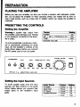
PRESETTMG THE CONTROLS
Setting the Amplifier
Warrang:A sudden high output from
the amplifter coukj damage yotr hearing
or the speakers connected to the ampHfia-'s output.
Control
PO\NER
MIC 1, MC 2, PHOISHD/AUX.CX
TONE
MASTER VOLUME
Skiing
Off
MIN
MID
0
To avoid accidentafty overdriving a channel or prenatur^ annplifying an aucfio
inpuL, set Vne amfifier's controls to tfie
levels ^lovm betow before you connect
ttre AC power cord or tum on povwer.
MikSTCB VnUiME
n i l IIIIPIIIIIIl
1
MXeX
MtCa
PMDHOL/AUX.CS
TONE
• . < ' ' ' ' l «
s
:(
MU>
MP*~at P . A .
MMI
MXW
MM
KIM
MM> LOU
MXOM • ' X . ^
)::
./*^*
AMm.TT'teB. t « a v . . ^ e v
Setting the Input Source
To avoid sudden audio from the input
sources, set ther controls to tfie levels
^tovim betow before you connect their
output jacks to the annplifier's input
jad(S.
AucfioDevkw
Turntable
Tape Deck
CD Player
Amplifier/Receiver
Power
Power
Power
Power
Tone
Selling
Off
Off
Off
Off
Flat
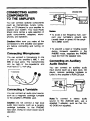
CONNECTING AUDIO
COMPONENTS
TO THE AMPUFIER
You can connect optional comporents
(such as miCTophones, tuners, turntables, or CD players) to your amplifier to
expand your system. Your tocal Radio
Shack store canies a wide selection of
audio components, adapters, microphones, and speakers.
Cautton: Make sure you make all ttie
connections to ttie anrtplifier and ^aeakers before connecting and tuming on
power.
Connecting Microphones
You can connect a microphone to one
or both of the amplifier's MIC 1 and
MIC 2 input jacks. The mcrophone(s)
can be high- or low-impedance and
must have a V4 -inch plug.
QROUNDWRE
Notes
• To avoid a low frequency hum, connect your turntable's gpround wire
(usually blad< or green) to the amplifier's GND screw.
» To prevent a tjeat or howing sairKJ
during monaural operation in the
PHONO mode, s^iarate the PHONO
input line from the ^Deaka- wire.
Connecting an Auxifrary
Audio Source
You can connect an auxiary audo
input source (such as a tape deck, CD
player, cerarrric cartridge turntable or
tuner) to the amp6fier's AUX.CO jack.
^
I mr["mum'
Connecting a Turntable
You can connect an audio input source,
such as a magnetic cartridge tumtatJle
to the amplifier's PHONO jack.
Cautton: Do not connect a high level
audio input source, such as a ceramic
cartridge turntable, to the PHONO
input jack. Doing so could cause sound
distortion.
^
^JSSHJO
Note: To connect a stereo audto
source to the AUX.CO jack, use a
shiekled Y-adapter, s u * as Cat. No.
42-2438 (not suppled).
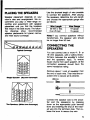
PUCING THE SPEAKERS
Sf»aker ptecanait depencte on your
room's size and anrangerr^it We recommaxJ you piay a wide-range recorcfing and experiment with speaker
placement until you firto the locations
ttrat result in the best sound. The foBowing drawings ^x)w recommerxjed
qjeaker placements for typical, nanow,
aixl wkJe sound coverage.
lypteal Covofsge
*^oo9•$oo9-Q009.
.QooQ-
I#l't\
Sngia Spsaksr (Nanow Ccwsrsse)
b 0 0
Use the ^tortest latgth of wire possitde
to connect the qaeakers. After placing
the speakers, detemnine the vinre length
and choose tfie apfiv'opriate gauge size
as foUows:
Wire Length
25 feet or less
Over 25 feet
Note: If you connect speakers without
transfomners, the speaker wire shouto
be no longer than 50 feet
CONNECTING THE
SPEAKERS
You can connect one or more 4-, 8- or
16-ohm speakers, with or wittraut transformers, between the amplifier's output
and the speakers' input To ensure
equal volume from each speaker, all ttre
connected speakers should have the
same impedance rating.
Remove about 1 inch of insulation from
the end of each wire. Then twist tfie exposed wire to secure all its strands.
0 ^
b 0 c_o3) 0 c_o5>0 d 0 ^
> 0 j^oS-
IW0 Speakers (WMe Area Coverase)
Wire Gauge
18-gauge
16-gauge
W///C
•
•
Connect tfie speaker wire to the amplifier and the speaker(s) by pressing
down on the appropriate push terminal
lever and inserting the end of ttie twisted wire into Hie terminal's hole. Then release the lever to secure the vwre.
• Speakers are connected in series
when the first ^Deaker's poative termrial is corBiected to the next speaker's negative terminal. Determine the
total speaker impedance of speakers
connected in series by adcBng up the
individual impedances of afl the connected speakers.
Phasing the Spe^ricers
Proper ptia^g is important when you
use more ttian one speaker in ttie same
room or area. Out-of-phase speakers
can lose up to one-half of ttieir potential
volume, and can have a significantty decreased bass effect.
For exampte, if you want to connect
two 8-ohm ^leakers in series, add 8
(ttie impedance of cme speaker) plus
8 (ttie impedance of the other speaker) for a total speaker impedance of
16 dims.
COM 4 0 8CJ ISO 70V
Most speaker terminals are cotor-coded
or have a mark that indicate ttie terminal's potenty. Usually, terminals with
positive polarity are red or have a plus
symbol (+), and terminate vwth negative
polarity are black or have a minus symbol (-).
Ptiasing is con-ect v^rtien you connect -F
to -F and - to -.
Detemiining Total Speaker
Impedance
Caution: A total speaker impedance
that is higher than 16 ohms or tower
than 4 ohms can damage your amplifier
or speakers.
Before you connect speakers to the
amplifier, you must determine the total
speaker impedance. In determining the
total speaker impedance, you must first
detemnine if your speakers are connected in series, paraUel, or a series/parallel
combinatton.
• Sprakers ere comected in parallel
v^rtien afl ther negative taminals are
connected to^tfier and afl their positive terrrwiate are connected together.
Determine the total speaker impedance of speakers connected in parallel by dividing the inipedance of one
speaker by the number of speakers.
For exam|:te, if you plan to connect
two 8-ohm speakers in paraUel, divide 8 (the impedance of one speaker) by 2 (the rsjmber of speakers) f a
a total speaker impec^ce of 4
ohms.
COM 4 0 8 0 160 70V
8Q^
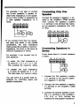
Connecting Orriy One
Speaker
Connect the speaker's negative (-) terminal to the amplifier's COM tenrrwial.
Then connect the ^leaker's positive
(-F) terminal to the terminal that matches the speaker's impedance (4Q, 8Q,
or 16Q).
isn 70V
an
• If you connect more than two speaka s usng only seri^ or only paraBel
comecttons, the total impedance
might exceed the amplifier's maximum
impedance (16 ohnrs) or fafl below its
mininrHjn impedance (4 ohms).
For example, if you connect four 8ofvn speakers:
Connecting Sg;»aker8 in
Series
Follow these steps to connect speakers
in series.
COM 4 0 8 0
160 70V
-In series, ttie total impedance is
32 ohms (8 -F 8 -f 8 -F 8 = 32).
This exceeds the maximum rating.
-In paraflel, the total impedance
is 2 ohms (8 divided by 4 = 2).
This fafls bdow the minimum rating.
You can anive at a proper total impedance by combining series and
parallel ccmriections.
8U
1. CannecA the first speaker's positive
(-F) terminal to the second speaker's negative (-) termirral.
2. Connect the first speaker's negative
(-) terminal to the amplifier's COM
tenninal.
3. Connect the second speaker's positive (-F) terminal to the amplifier's
4 Q , 8 Q , or 16 Q temninal that
matches the toal speaker impectence.
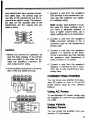
Connecting Speakers in
Parallel
1. Group the four speakers into two
pairs.
Fdtow these steps to connect speakers
in parallel.
2. Connect eadi pair of speakers in
series. The total impedance of each
pair is 16 ohms (8 + 8 = 16).
CDM 4 0
8 0 160 70V
3. Connect the two pairs of speakers in
parallel. The total impedance of both
pairs is 8 ohms (16 / 2 = 8).
1. Connect the speakers' negative (-)
tenninals together.
2. Connect the speakers' positive (-F)
tenninals together.
3. Connect the speakers' negative (-)
terminals to ttie amplifier's COM terminal.
4. Connect both speakers' negative (-)
terminate to the ampfifier's COM terminal.
5. (Connect both ^jeakers' positive (-F)
terminate to the ampfifier's 4Q, 8Q,
or 16Q terminal that matctws the
total speaker impedance.
Connecting Speakers with
Transformers
4. Connect the speakers' positive (-F)
terminals to the amplifier's 4£2, 8 2 ,
or 16Q tenninal that matches the
total speaker impedance.
For the best results when you connect
two or more speakers to your system,
we recommend you use a line trans-former (such as ( ^ t No. 32-1031, not
suppfied) tar each speaker.
Connecting Four Speakers
in Series/Parallel Combination
Transfomiers offer ttiese advantages:
Follow these steps to connect four
speakers in series/parallel combrtation.
COM 4(1 s n i s n
TOV
KI<IIQK3l>Za)E<|
LjiSllSIJiill:?^
^^y^^
160
8
• You can connect speakers with different impedance without causrig differences in output between the speakers.
• You can add or remove a speaker
from tfie system wittxxit having to recateulate ttie entire system's impedance.
• You can reduce signal loss wfien you
use speaker wire over 50 feet tong.
Line transformers have several connectors cafled taps. The primary taps (on
one side of the transfonnner) are the inputs and are rated in watts. The secondary taps (cff) the opposite sicte of the
transformer) are the outputs and are
rated in ohms.
{SECONDARY)
Cauttons:
• Before you connect the speakers, be
ajre the total wattage of the primary
taps you intend to use does not exceed the ampfifier's maximum 20watt output power rating.
• Avoid multiple connections to the amplifier's 70V and COM terminals.
COM 4 0 a n
160 70V
1. Connect a wire from the ampliftor's
TOV tenninal to the transfomner's primary tap that matches your speaker's wattege ratFig.
Note: Usually, eac* speaker in a system uses the same wattage tap. If
you want a particular speaker to
have a higher volume level, use a
higher wattage tap on its transformer.
2. Connect a wire from the ampfifier's
COM (common) tenninal to the C
(common) taps on the transfomner's
primary side.
3. Connect a wire from the speaker's
positive (-F) terminal to the transformer's secondary tap that matches
the speaker's total impedance (4
ohms, 8 ohms, or 16 ohms).
4. Connect a wire from the speaker's
negative (-) tenninal to the C (common) tap on the transformer's secondary side.
CONNECTING POWER
You can power your amplifier from standard AC power or from a 12-vdt DC
power source (such as your vehide's
battery).
Using AC Power
CDM 4 0
80
160 70V
To use standard AC power, simply plug
the suppfied AC corcl into any standard
AC outiet.
Using Vehicle
Battery Power
(PRIMARY) (SECONDARY)
You can power the amplifier from your
vehicle's 12-volt battery.
Cautinn:
• Your vehide must have a negativeground dectrical system. If you are
unsure about what type of electrical
system your vehide has, ask your vehide dealer.
Cautfanu Use only an identical 5 x 20
mm, fast-acting, 2-amp, 250-volt fuse
(such as Cat. No. 270-1052).
Foflow these steps to replace tiie ampfifier's fuse.
1. Unpfijg the ampfifier's power cord.
• Disconnect the AC conj before you
connect tiie DC power cable.
To use 12-vott DC power, connect the
supplied DC power cable's small end to
the ampfifier's 12V NEGATIVE GND
jack. Then connect the cable's other
end to your vehide's cigarette-lighter
socket.
2. Usang a tiatislade saewdriver, push
and tijm tiie fuse holder's cap counterdockwise untfl tfie fijse holder
pops out.
Replacing the DC Cable's
Fuse
The cable's 4A, 125-volt in-line fuse
protects your ampfifier from voltage
surges. If tfie ampfifier's power indicator
does not light when you press POWER,
check the fuse. If it is btown, replace it
with a 4-amp, 125-volt fuse (such as
Cat. No. 270-1010, not supplied).
To replace ttie fuse, unscrew ttie tip of
tiie dgarette-lighter plug. Then remove
the old fuse and insert tfie new fuse.
Secure tiie fuse by reattedwig the
plug's tip.
Replacing the Amplifier's
Fuse
The fuse (located on ttie back of ttie
ampfifier) protects your ampfifier from
power (vottage or cunrent) surges. If ttie
POWER Hidicator does not light wfien
you press POWER, tiie fuse might be
btovm.
10
3. Remove ttie fuse holder and repbce
ttie fuse.
4. Usrig a flatt}lade saewdriver, push
and tijm ttie fuse holder's cap fuOy
dockwise to replace it.
VEHICLE INSTALLATION
Before you install ttie ampfifier in your
veNcle, read the foltowing hints to help
you select a proper mounting location:
• OKWse a mounting location in your
vehide where all ttie amplifier's controte are easy to reach but do not interfere with ttie operation of the vehide. Ttie most common location is
under ttie dashboard directly over ttie
drive shaft hump.
• Be sure all wires and cables are
away firom the brake, clutch, and accelerator.
• Be sure the mounting location afiows
enough leg room for passengers.
After you select a mounting tocation, follow tiiese steps to mount tine amplifler
in your vehide.
1. Position tiie left and right mounting
brackets on tiie desired mounting
surface and nnari< tine mounting
holes.
2. Use a drill vwth a Va-inch bit to drifi
holes on the marked location.
3. Mount the brackets using a universal
mounting bracket set (Radio Shack
Cat. No. 270-023).
4. Attach the amplifier to tiie brackets
using the machine screws.
• Mount ttie ampfifier so you can easily
remove it for service or maintenance.
• Do not mount the ampfifier in the air
stream patii of a fieater or air conditioner.
11
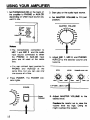
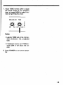
US6NG YOUR AMPUFSER
1. & t PH0N0/AUX.CD on the back of
tiie asnfMBt to PHCM^iO or AUX.O)
dependir^ on whidi fiiput soirce yoj
want to mb(.
3. Start play on ttie aiKlto input soiree.
4. Set MASTER VOLUME to 10 (mid
position).
MASTCR VWJUMC
• IS
MJXXD
VAS
|«i«
a./
^fl
•*v
B*V^
@
• The micnophones connected to
MIC 1 and MIC 2 and tiie audto
input source connected to eitiier
tiie PHONO or AUX.CD input
jacks are all used at tine same
time.
• You can connect input sources to
PHONO and AUX.CO at ttie
same time, but you can use only
one source at a time.
2. Press POWER. The POWER indicator ligtrts.
Str
5. Adjust M C I , MIC 2, and PHONO/
AUX.CO to the desired volume and
balance.
MICl
MXM
MUI
HICa
MSM
MMI
PHBO^AUX.CB
mitt
MAM
UZrrCR.tSOVy'K
Ptmrar
Indicator
6. Adjust MASTER VOLUME to ttie
desired tovel.
Caution: Be careful not to ratee ttie
votome level tcx) hig^. Doing so
might overioad the system.
12
7. Adust TONE toward LOW to adjust
the sound toward a bw fi-equency
tone, or toward HIGH to adjust it toward a high frequency tone.
OMOXAUX.CS
MIN
tiMt
TONC
LOW
HXMI
•
^
Notes:
• Leaving TONE set at tiie mid position produces a flat, unacQusted
tone.
• If feedback occurs, ftjm TONE toward LOW or tum down the volume.
8. Press POWER to ttjm off tiie ampfifier.
13
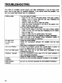
TROUBLESHOOTING
Your N^A-31 Ampfifier ^KuJd require vay fittte maintenaiiue. If yoj do have problans, refer to ttis chat for posatde adutiars. If yoi csffnot soto the probton, cottact your locd Radto Shack ^ore tor assstance.
Nottwig works
If you are ifiing AC pcmer.
- Qeck tiie AC tase (an tte track peffei). ff t t s fuse is btanm.
r^idace it witii a 2-An^, 2S0-ydi t e e ( a e T^qafBcgrg the
Ampfifier's Fuse' on Page 10).
- CtTBck to rreisaatsethBAc auflet hee pouKr.
- Ctitsjk ttm powoi!) conneaians to tne rest ot atn s^saenx (ttimtatte, QD pdaya-, tur^, ete.)
If you are usng vehide ballery povra:
- Qieck ttce DC cahlR's fii-frie ftos. If tte fuse B tiOiai, replace
it \ASBi a 4-Mnp, 1S-Vatt fuse ( s e Ttupauny Um DC Cauu s
Fise" on P a ^ 10).
- Cteck to rr^ce sue the velide boUuy IBS pa!t&.
- QitHjK to n'QKe sure tre u u aoapier e> picqjuiiy cwuviaBU.
Make sure nane af tte s p m k g vmr\Q, iiiiuupImB cables, or
No signal from
an audio mpiA
source
Hum from PHONO
Hum trom other inputs
Feedtiack "squeate"
Ampfifier
ovwheats
Weak spe^ar^xjnse
14
ultier cuiiiiticuiiy ijiiiinfi am oeiective.
Qieck the corrtrol setting.
Check trie coiviectKuis between Die ampfier and Ihe ffiput
source.
Make sure a microphone is not ddectrve.
Connect ttie tumtabte's grourwl wire (usirfy tibck or green) to
one of ttie (2*03 screws on ttie tack of tiie ampfifier.
Make sure ttiere are no tow level infxils connectal to tt«
PHONO/AUX.a3 jack.
Move trie nucroptione furtrisr a>«ay from trie output qaeakers or
useadrecttoral iniaophone.
Adjust Uiti TONE cuiitfuls if necessary.
Be suie you Imve puviued arlRfpHlB vaitdauon tu ttie aiiipSfiei.
Be sure you ccrrectiy cakaj^ted ttie total spe^et mipedanui.
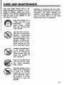
CARE AND MAINTENANCE
Your new Radto Shack MPA-31 20Watt A(^ot)ite PA Ampfifier is an exampto of superior design and craftsmanship. The fofiowing suggestions wiD
help you care for ttie amplifier so you
can enjoy it for years.
M(xlifying or tampering with tine ampfifier's intemal components can cause a
malfunction and might invalidate tine
wananty. If the ainplifier is not perfomning as it shouto, take it to your local
Radio Shack store for assistance.
Keep tiie amplifier dry. If
it gets wet, vnpe it dry
imme<jiately.
Liqutos
might contain minerals
ttiat can conode elech-onic circuits.
Use and store the amplifier only in normal temperatijre environments,
and avoto sudden temperatijre changes. Temperature extremes can
shorten the life of electi-onic devices and distort or melt plastic parts.
Handte tiie amplifier gently and carefully. Dropping it can damage tine
droiit boards and can
cause tine amplifier to
work improperiy.
Keep tine amplifier away
from dust and dirt, which
can cause prematijre
wear of parts.
Wipe tiie amplifier vinth a
damp doth occasionally
to keep the ampfifier
looking new. Do not use
harsh chemicals, deaning solvents, or sttong
detergents to dean the
amplifier.
15
SPECIRCATIONS
(ii^xit Poww at 4 C»Tms 1 W4z, 1 0 % T m
Power BandMslth at 5W, 10% THD, A M Irput
20 Watte
193 Hz-20 kHz
T.H.D at lOW, 1 kHz wflth a) kHz Low Pass Fiter
M1C1
MIC 2
AUX.CD
PHONO
022%
0,21 %
0.20%
0.24%
Input Sensitivity at 10% THD, 1 kHz
MIC 1
MIC 2
AUX.CD
PHONO
Z5mV
2^mV
150 mV
2^nriV
Signal to Nose Ratio (Input Shortaj) witin 30 kHz Low Pass FBter
MIC 1
MIC 2
AUX.CD
PHONO
Frequency Response at 4 OTTTS -F 1/-3 dB
M1C1
M1C2
AUX.CD
PHOtMO (RIAA 1(X) Hz/10 kHz)
Hum and Ndse at 4 Otms with 30 kHz Low Pass FSla
at Master Volume N/fri
at Masta- Votffne Max aid Othas N/in
Torre Ctontrd (His^ Cut at 10 kHz)
Power ReqtWBTieit
Omenstons(HWD)
Waght
16
60 dB
60cfi
;,... ffidB
60 cB
:ia)Hz-15kHz
1K)Hz-15kHz
ia)Hz-15kHz
-1-11.9 cE/-1Z1 cffl
3 mV
30 mV
- 1 5 cffl
120V AC 60 Hz
3 x 11 VA X 83/4dndtes
7.7 bs
NOTES
17
NOTES
18
kV
19
RAOIO SHACK LIUfTED WARRANTY
This product is warranted against defects for 1 year from date of purchase
from Radio Shack company-owned stores and authorized Radio Stiack
franci lisees and dealers. Within this period, we will repair it wrttiout charge for
parts and labor. Simply bring your R s t o Shack mIes slip as proof ot
purchase date to any Radio Shack store. Warranty does not cover
transportation costs. Nor does It cover a product subjected to misuse or
accidental damage.
EXCEPT AS PROVIDED HEREIN, RADIO SHACK MAKES NO EXPRESS
WARRANTIES AND ANY IMPLIED WARRANTIES ARE LlMrTED IN
DURATION TO THE DURATION OF THE WRITTEN LlMfTED WARRANTIES
CONTAINED HEREIN. Some states do not permit limitation or exdusion of
Implied warranties; therefore, the aforesakj limitation(s) or exclusion(s) may
not apply to the purchaser.
This warranty gives you specitic legal liglils and you may also have other rights whidi
vary fronn state to state.
We Service What We Sell
RADtOSHACK
A D M ^ o n <a T ^ K ^ Corporation
Fort WorOi, Tttas 761Q2
8A4
aw