1
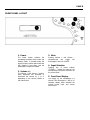
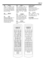
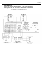
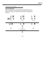
PAGE 1
INTRODUCTION
Congratulations on your purchase of the Aragon Soundstage. The Soundstage was designed to
eliminate the need for a separate two-channel music system, and home theater system. We
have integrated an audiophile quality two channel analog preamplifier, based on the design of
the Aragon Aurum, and a top-level digital surround sound processor into an easy to use
preamp/processor.
The Soundstage maintains a simple design allowing audio and video to be selected at the push of
a button, while it also has numerous advanced features that allow the preamp/processor to be
tailored to best suit the system around it. As there are many advanced features available, you
will get the most out of the Soundstage if you read through this owners manual. The Version
Number of the owners manual is located at the bottom of this page. Updates will be provided on
our website at
http://www.mondialdesigns.com/aragon
on the Soundstage page, in pdf format. Adobe Acrobat Reader is required to download this file
and view it on your computer and a link is provided on the website to download this free reader.
Please be sure to send in your warranty card so we can keep you informed about
updates to the Soundstage.
On the website, you can also add your email address to our email update list to be sure that you
will be provided with notices on future upgrades, and other information.
Mondial Designs
20 Livingstone Avenue
Dobbs Ferry, NY 10522
Email: [email protected]
www.mondialdesigns.com
Version Number 1.5
Manufactured under license from Dolby Laboratories.
"Dolby", "AC-3", "Pro Logic" and the double-D symbol are trademarks of Dolby Laboratories.
Confidential Unpublished Works. p1992-1997 Dolby Laboratories, Inc. All rights reserved.
Manufactured under license from Digital Theater Systems, Inc. US Pat. No. 5.451.942 and other worldwide patents
issues and pending. "DTS" and "DTS Digital Surround" are trademarks of Digital Theater Systems, Inc. p 1996 Digital
Theater Systems, Inc. All rights reserved.
PAGE 2
TABLE OF CONTENTS
SOUNDSTAGE FEATURES
4
FRONT PANEL DISPLAY SETUP WALKTHROUGH
6
FRONT PANEL LAYOUT
8
REAR PANEL CONNECTIONS
9
REAR PANEL OUTPUTS
10
REMOTE CONTROL
11
INPUT CONNECTIONS
13
AC INPUT
DIGITAL INPUTS
ANALOG INPUTS
VIDEO INPUTS
MULTI CHANNEL ANALOG INPUT
VIDEO EXPANSION PORT
SUGGESTED CONNECTION DIAGRAM
13
13
13
13
13
14
14
GENERAL OPERATION
15
INPUT SELECTION
AUTO-FORMAT DETECTION
VOLUME ADJUSTMENT BY SOURCE
VARIABLE EQUALIZER
ON-THE-FLY ADJUSTMENTS
EQUALIZER
STEREO DIRECT
SIX CHANNEL ANALOG INPUT
NIGHT MODE
DISPLAY
DIGITAL/ANALOG SELECT
MUSIC MODES
15
15
15
15
15
15
16
16
16
16
16
16
PAGE 3
ADVANCED FEATURES
17
LEVEL ADJUSTMENTS BY MODE
BASS MANAGEMENT
SEPARATE BASS MANAGEMENT SETTINGS FOR STEREO
ANALOG INPUT LEVEL
SEPARATE AUDIO AND VIDEO INPUT SWITCHING
SYSTEM LOCK
FRONT/REAR BALANCE
17
17
17
17
18
18
18
CUSTOM MENUS
18
1. SCROLL TEST TONES
2. TEST TONE OFF
3. SEPARATE ON/OFF
4. AUTO POWER ON
5. POWER ON VOLUME
6. AUTOMUTE ON INPUT
7. CUSTOM INPUT NAMES
18
19
19
19
19
19
19
ADDITONAL FEATURES
20
PROGRAM FORMAT DISPLAY
REMOTE CONTROL
20
21
MODES
22
DOLBY DIGITAL
STEREO DIRECT
SIX CHANNEL ANALOG INPUT
PARTY
HALL
22
22
22
23
23
PAGE 4
SOUNDSTAGE FEATURES
Two Channel Analog Preamplifier
The Soundstage offers an audiophile quality two channel analog preamplifier, based on the
design of the Aragon Aurum. Each analog input on the Soundstage can be configured as a
Stereo Direct input. Configured as a Stereo Direct input, the analog signal bypasses the DSP
module allowing for uncompromised analog reproduction. This allows for analog only sources to
be connected without unnecessary degradation from conversion to the digital domain and back
to the analog domain. Super Audio CD players, and DVD Audio players can be connected via
their analog outputs and retain the full fidelity of the new formats.
Full Autoformat Selection
The Soundstage will automatically determine what format a digital bitstream is encoded with, and
switch the system to that mode. Separate level settings are available for each mode, and are
automatically loaded whenever a new mode is loaded. This allows the system to be operated at
the push of a button.
Analog Domain Volume Control
The Soundstage channel balance, and overall volume settings are adjusted in the analog domain
to retain the full resolution of all formats
Fully Hardware and Software Upgradable Design
As the market changes, the Soundstage can change with it. With a modular design, and
upgradable software, we can implement changes in the design to accommodate new formats, or
changes to old formats, and apply these changes to the Soundstage. The analog output section
is set up with 2 channel output cards that can be modified, or more can be added, to
accommodate future formats with 7.1, or more channels. Digital expansion ports are provided
for future digital inputs such as for DVD-Audio, and Super Audio CD. Video expansion ports are
provided for up and coming formats such as component video switching.
Balanced and Single Ended Outputs for All Channels
The Soundstage is provided with both Single Ended (RCA) and Balanced outputs for each
channel. These outputs can both be used simultaneously to provide a tremendous amount of
flexibility in system setup.
24 Bit D/A Converters for All Channels
The Soundstage utilizes high quality 24 bit Crystal Semiconductor D/A converters for all six
channels. This module is also upgradable to accommodate future formats with more advanced
D/A converter needs.
Six Channel Analog Input
The Soundstage provides a six channel analog input to allow direct connection of DVD players
with built in decoders, such as those expected for DVD Audio. A DB-25 connector is located on
the back panel.
PAGE 5
Combination Digital Domain/Analog Domain Bass Management
The Soundstage utilizes an advanced system for Bass Management that allows the system to
retain the full dynamic range of the signal when accommodating any loudspeaker system. High
pass and low pass crossover filters, and bass summing to the subwoofer is performed in the
digital domain. This allows for more precise crossover filters. In a system that does not utilize a
subwoofer, the low frequency signals (including the LFE channel in Dolby Digital, and DTS) is
combined with the large speakers in the system in the analog domain. This eliminates any need
for digital domain attenuation when these signals are combined. Processors that perform this
function in the digital domain (which constitutes the majority of processors on the market) must
attenuate the channels to avoid overload in the DSP processor. This results in a loss of dynamic
range which can greatly effect the sound quality.
Analog Domain Dialog Normalization
To retain the same overall level from Dolby Digital, regardless of the source, Dolby requires that
all Dolby Digital processors perform Dialog Normalization. The Soundstage has the unique ability
to perform this normalization in the analog domain. If this function were performed in the digital
domain the result would be a loss of dynamic range due to attenuation in the DSP processor.
Adjustable Crossover Point
The Soundstage allows you to choose between Large and Small speakers, for each set of
speakers (Front, Rear, and Center) and to adjust the crossover frequency that these small
speakers utilize. There are nine different crossover frequencies to choose from. Separate
crossovers can be selected for Stereo mode, and Surround modes.
Separate Level Settings for Each Mode
Through the front panel setup guide, the channel balance for every mode can be set. For more
precise setup, channel balances can be adjusted individually for each mode. These levels are
automatically loaded whenever a new mode is loaded.
Speaker Selection Grid
The center portion of the remote control is laid out to represent an overhead view of your
speaker system (See page 21) With this lay out, it is easy to access each speaker during setup
without having to constantly focus on the remote control.
Individual Selection of Audio and Video Sources
With the push of a button, the audio and video -can be selected independently of each other.
This allows you to watch one source, while you listen to another without any complicated setup
menus. By first selecting your video source, and then selecting your audio source, pressing the
audio source a second time will switch the video signal back to the previously selected source.
Pressing the audio source again will switch the video output back to the original source.
PAGE 6
Front Panel Display Setup Walkthrough
The Soundstage is equipped with an easy to use Setup Guide that will walk you
through the initial setup procedures.
It will provide settings for bass
management, delay, and individual speaker levels. All these settings can be
further adjusted in more detailed menus within the Soundstage.
The key to setup of the Soundstage lies in the remote control, and the Speaker
Selection Grid. The center of the remote, outlined in gold, contains all the
buttons necessary for setting up the processor. The Speaker Selection Grid is
laid out as your speakers would be laid out in your listening room. (see page 21)
The LVL UP[FF] and LVL DN[REW] buttons perform any adjustments to the
current field.
The SEL/PLAY button at the center of the Speaker Selection Grid is used to enter
your selection and continue on through the Setup Guide.
PRESS THE GUIDE BUTTON TO ENTER THE FRONT PANEL SETUP GUIDE
The Front Panel Setup Guide will take you through the following steps:
SPEAKERS YOU HAVE
SEL/PLAY TO CONTINUE
In this section you will select the speakers that you have in your system, and
indicate the “size” of these speakers. [For more information on speaker “size”
please see the section on Bass Management] Press the SEL/PLAY button to begin
this portion of the setup procedure.
CENTER:LARGE
You can select Large, Small, or None. Use the LVL UP and LVL DN buttons to
change your selection, and press the SEL/PLAY button to continue.
FRONT SPEAKERS:LARGE
You can select Large, Small, or None. Use the LVL UP and LVL DN buttons to
change your selection, and press the SEL/PLAY button to continue
REAR SPEAKERS:LARGE
You can select Large, Small, or None. Use the LVL UP and LVL DN buttons to
change your selection, and press the SEL/PLAY button to continue
SUBWOOFER:YES
You can select YES, or NO. If you do not have a subwoofer connected to the
system at the subwoofer outputs, select NO. Use the LVL UP and LVL DN
buttons to adjust.
SPEAKER DISTANCES
The next section allows you to indicate the distances from each speaker to your
listening position. This is necessary in order to provide the proper delay settings
for each speaker. The distances are measured in feet to the nearest half-foot.
PAGE 7
Measure the distance from the indicated speaker to the main listening position.
The distances are adjusted with the LVL UP, and LVL DN keys. The SEL/PLAY
button enters the selection, and continues on to the next speaker. For the delay
settings to be set properly, distances are measured for all 6 speakers in the
following order: Left Front, Center, Right Front, Rear Right, Rear Left, and
Subwoofer.
SPEAKER LEVEL SETUP
The last section allows you to adjust your speaker level settings. An SPL meter
can be used, or they can be adjusted by ear. The more accurate method will
depend on your listening room, as well as your particular speakers. The test
tones will scroll to each speaker in two-second intervals. The LVL UP and LVL
DN keys are used to adjust the level of each channel. While seated at the
listening position, you should adjust the speaker settings to output the same
level from each channel. Once this has been completed for all channels, exit the
setup guide by pressing the SETUP button.
Your initial setup is now completed. Channel balances have been set for all
modes. More advanced adjustments, such as adjusting the channel balances for
each mode individually are available to further tailor the performance of the
Soundstage to best suit your listening environment, and personal preferences.
PAGE 8
FRONT PANEL LAYOUT
1. Power
The Power button switches the
Soundstage between Active mode and
Standby mode. In Standby mode, the
analog circuitry remains active while the
DSP module is shut down, and the
preamplifiers outputs are muted.
2. Volume +/-
The Volume + and Volume – buttons,
when depressed, will increment or
decrement the volume by 1, or .5
depending on the current position of
the volume level.
3. Mute
Pressing Volume + and Volume –
simultaneously
will
toggle
the
Soundstage in and out of MUTE.
4. Input Selection
Pressing any of these buttons
(TV/DVD/…..) selects the input at the
corresponding rear panel connection as
the current input.
5. Front Panel Display
The display on the Soundstage is a
Vacuum Tube Fluorescent, 2 line by 20
character display which indicates the
present format, input, and volume
control level.
PAGE 9
REAR PANEL CONNECTIONS
Be certain that the Soundstage Preamp Processor, your amplifiers, and all other associated
equipment is powered OFF before making or breaking any connections to the preamplifier.
Failure to do so may result in damage to your speakers, or other equipment.
1. ANALOG INPUTS
Eight stereo analog inputs are
provided on the rear panel.
The analog inputs are labeled
for convenience only, and any
line level source can be
plugged into any of analog
inputs. (see also Analog Input
Level control)
2. DIGITAL INPUTS
Eleven digital inputs are
provided on the rear panel
including eight Coaxial, and
three Toslink.
These can
accept the digital signal from
any device outputting a
standard S/PDIF signal. On the
TV, DVD, and CD/LD inputs,
the
Toslink
input
takes
precedence over the Coaxial
input. Both may be connected
simultaneously.
3. COMPOSITE VIDEO
INPUTS
Eight composite video inputs
are provided on the rear panel.
When a source is selected, the
corresponding video input is
also selected and routed to the
Monitor and Record outputs.
Video inputs can also be
selected independently from
the audio input. (See selecting
a separate video source)
4. S VIDEO INPUTS
Eight composite video inputs are
provided on the rear panel. When
a source is selected, the
corresponding video input is also
selected and routed to the Monitor
and Record outputs. Video inputs
can also be selected independently
form the audio input. (See
selecting a separate video source)
5. VIDEO EXPANSION
PORT
The Video Expansion Port
(when
available)
allows
switching of three different
Component video, RGB Video,
or HDTV video signals. The
Video
Expansion
inputs
correspond to the TV, DVD,
and VCR input selections.
6. RS-232 IN/OUT
The RS-232 port allows the
Soundstage to be connected to
external control devices to
provide 2-way communication,
or to expansion boxes for
future upgradability.
7. IR INPUT
The external IR input on the
rear panel allows for an
“electrical” connection of the
infrared
signal
to
the
Soundstage from an external
IR receiver. The IR data is
transmitted to the Soundstage
IR receiver by an internal; IR
LED
8. MULTI-CHANNEL
ANALOG INPUT
A DB-25 connector is provided
on the rear panel to allow a six
channel analog input from a
DVD player, or DVD-A player.
Six RCA to DB-25 adapters are
readily available from many
manufacturers. See diagram
for proper connection. This
input
bypasses
the
DSP
module.
9. DVD-AUDIO DIGITAL
INPUT
A slot has been provided on
the rear panel to accommodate
the digital output from a DVDA player once that specification
has been established.
10. AC INPUT
Power is connected to the
Soundstage by a standard IEC
3 wire power cord.
PAGE 10
REAR PANEL OUTPUTS
1. VIDEO EXPANSION
PORT OUTPUT
The Video Expansion port
(when available) will provide
one set of
RGB/Component/HDTV output
jacks.
2. S VIDEO MONITOR /
RECORD OUTPUT
Two outputs are provided for S
video signals to route them to
your monitor, and/or recording
device. The Soundstage does
not convert composite video
signals to S video although
both composite and S video
signals can be used
simultaneously.
3. COMPOSITEVIDEO
MONITOR / RECORD
OUTPUT
Two outputs are provided for
composite video signals to
route them to your monitor,
and/or recording device. The
Soundstage does not convert
composite video signals to S
video although both composite
and S video signals can be
used simultaneously.
4. TOSLINK DIGITAL
OUTPUT
A Toslink digital output is
provided on the rear panel.
The signal from the selected
digital source is routed to the
Toslink digital output for
recording purposes.
7. SINGLE ENDED (RCA)
PREAMPLIFIER
OUTPUTS
Single ended RCA outputs are
provided for each channel.
The single ended, and
balanced output connections
may be used simultaneously.
5. ANALOG RECORD
OUTPUTS
Two sets of outputs are
provided on the rear panel to
connect to recording devices
such as VCR’s and Tape Decks.
The analog signal from the
selected source is routed to
both record outputs. (Caution
should be used when
connecting these to a VCR line
input, with the VCR as the
selected source, while lien in is
selected on the VCR. This can
cause a feedback loop)
8. RS-232 IN/OUT
The RS-232 port allows the
Soundstage to be connected to
external control devices to
provide 2-way communication,
or to expansion boxes for
future upgradability.
6. BALANCED
PREAMPLIFIER
OUTPUTS
Balanced output signals are
provided for each channel.
They can be used
simultaneously with the single
ended RCA outputs.
9. 5 VOLT DC OUTPUT
The 5 volt DC output can be
used to trigger the RPC-120
(see accessories page) or other
external devices that are driven
by a 5 volt continuous DC
output. (See also Connection
diagrams)
PAGE 11
REMOTE CONTROL
1. AUD
The AUD button selects the
Soundstage as the current
PAGE on the remote. It can
also be used to send a
separate ON command when
configured as such in the
custom menus . (see custom
menus)
2-8 Device Buttons
Selects the PAGE that the
remote is on. By entering the
appropriate Set Up code
number, each page can be
programmed
to
control
different devices in your
system. If the device is not
preprogrammed in, it can
“learn” new commands. (See
Appendix A: Remote Setup) for
more details
9. POWER
The POWER button is used to
toggle the power of the
Soundstage on and off. It can
be configured as a power off
button in the custom menus.
(see custom menus)
10.
MUTE
Toggles between mute, and the
normal volume setting.
11.
T/V
Future use.
12.
VOL UP
Increments the output level by 1
dB, or .5 dB depending on the
current location of the volume
control.
13.
VOL DN
Decrements the output level by
1 dB, or .5 dB depending on
the current location of the
volume control.
14. CH UP
15.
CH DN
16.
CENTER
17.
SUBWOOFER
18.
LVL UP
Selects the Center channel
level adjustment. Also scrolls
up the Custom Menus.
Selects the Subwoofer level
setup. Also scrolls the Custom
Menus down.
Adjusts level settings
Toggles menu settings.
19.
up.
LVL DN
Adjusts level settings down.
Toggles menu settings.
20.
SEL/PLAY
Enters the Analog Input Level
adjustment when accessing an
analog signal. Continues to
next menu option in the Setup
Guide.
21.
GUIDE/LEFT
Enter/Exits the Setup Guide.
Selects the Left Front channel
for level adjustment.
22.
MENU/RIGHT
Enters/Exits the Custom Menu
options.
Selects the Right
Front
channel
for
level
adjustment.
23.
L.REAR
Selects the Left Rear channel
for level adjustment. Adjusts
Front Rear balance in multichannel modes.
24.
R.REAR
Selects the Right Rear channel
for level adjustment. Adjusts
Front Rear balance in multichannel modes.
25.
BMGMT
26.
NIGHT
While in the Setup Mode,
enters and exits the Bass
Management options menu.
While in the Bass Management
options menu, enters and exits
the Crossover selection menu.
While in Dolby Digital mode,
enters and exits the NIGHT
compression mode for late
night viewing.
27. SHIFT
Allows buttons on the remote
to perform a "second function".
Not all buttons have a second
function available.
28.
DELAY
29.
A
30.
DISPLAY
Turns on and off the variable
equalizer for that particular
mode.
The variable EQ
remains active for a particular
mode until it is turned off in
that mode.
Turns the front panel display,
and the source indicator LED
on and off.
31.
EQ
32.
B
33.
C
34.
Bass
Turns on and off the fixed
equalizer.
Future use.
Future use.
Adjusts the variable bass
equalizer. Pressing this button
turns on the variable equalizer
if it was off, and enters the
menu to adjust the bass EQ
level (-6 to +6 dB)
PAGE 12
35.
Treble
Adjusts the variable treble
equalizer. Pressing this button
turns on the variable equalizer
if it was off, and enters the
menu to adjust the treble EQ
level (-6 to +6 dB)
36.
Future use
37.
ENTER
6CH
Selects the current input as a
Six Channel analog input.
When the current input is a
digital input, selects between
the digital signal, and the Six
Channel analog input.
38.
PRO L.
When accessing a PCM, or
Analog Signal, selects Pro Logic
as the current decoding mode.
When accessing a Dolby Digital
signal, switches to Pro Logic
decoding of two channel
signals.
39.
STEREO
When accessing a PCM, or
Analog Signal, selects Stereo
as the current decoding mode.
When accessing a Dolby Digital
signal, switches to Stereo
40.
SETUP
Enters and exits the Setup
Menu.
41-48. Input
Selections
Selects the current input
source. When the current input
selection is selected again,
toggles video inputs.
49.
A<>D
Selects between the Analog
and Digital input of the
currently selected source.
50. MODES
Toggles between DSP modes.
PAGE 13
INPUT CONNECTIONS
The Soundstage allows for analog, digital and video outputs for eight sources to be
connected to the rear panel inputs (Theoretically, up to 19 sources can be connected to
the Soundstage. See Advanced Adjustments section for more information on connecting
more than eight sources)
The Soundstage allows you to switch the Audio and Video signals independently of each
other. For easiest operation, the digital, analog and video outputs from each source
should be attached to the same source input (lined up vertically) on the rear panel of the
Soundstage. If different types of video outputs are available, one of each type (S Video,
Composite, and Component/RGB/HDTV when available) can be connected to a single
source input. This ensures that video output will be available regardless of the input
selected on the monitor.
AC Input
Using the supplied IEC power cord plug the Soundstage into the wall outlet. For line
filtration purposes, as well as remote power control of the system amplifiers, and other
devices, the Mondial RPC-120 can be used which provides 4 switched, and 2 unswitched
outlets.
Digital Inputs
The rear panel of the Soundstage provides eleven digital inputs (3 Toslink, and 8
Coaxial). Any S/PDIF digital output can be connect to any, or all eleven digital inputs.
For inputs with both a Toslink and Coaxial digital connection, the Toslink will take
precedence. It is possible to connect both a Toslink and a Coaxial digital signal to a
single source input but only one can be operational at a time. There is no need to
“assign” the digital inputs, as one is provided for each source connection. For easiest
operation, the digital output of the source should be connected to the same source input
(lined up vertically) as the analog and video outputs of the source.
Analog Inputs
The rear panel of the Soundstage provides eight stereo analog line level inputs. The
analog output of any line level source can be connected to any, or all of the stereo
analog inputs. The input gain of the analog inputs should be adjusted for each analog
source that you have connected. The Soundstage will automatically lower the input gain
of a source if it detects an overload at the input.
For optimum performance, the gain should be adjusted to the highest point before
clipping occurs. (see Advanced Adjustments section)
Video Inputs
The rear panel of the Soundstage provides sixteen Video inputs.(8 composite, and 8 S
video) The Soundstage does not convert composite video sources to S video, or S video
sources to composite video.
Multi Channel Analog Input
The Soundstage provides a Six Channel Analog Input. This DB-25 connector can be used
to connect the analog outputs from a DVD player with a built in decoder. The Six
Channel Analog input is passed directly to the analog preamplifier section. Individual
level adjustment, as well as overall level adjustment is available for this input.
PAGE 14
Video Expansion Port
A slot has been provided for future video switching. This input will allow the switching of
three Component Video, RGB Video, or HDTV video input signals (or all three types
depending on your television)
SUGGESTED CONNECTION DIAGRAM
PAGE 15
GENERAL OPERATION
Input Selection
The input can be selected from the remote control, or the front panel. Analog Audio,
Digital audio, and video are all selected simultaneously. (Video can be switched
separately. See advanced features.) The inputs are labeled for convenience only. Any line
level analog output, or SPDIF digital output can be connected to any input.
Dolby Digital from a laserdisc player requires the use of an external RF demodulator.
Auto-format detection
When an input is selected, the processor will search for a digital signal, and if present,
will determine the format and switch to the proper mode. If no digital signal is detected,
the processor will default to the analog input. The Soundstage will automatically switch
to the digital input when one becomes present at the digital input for the selected
source.
Discrete surround formats such as DTS, and Dolby Digital will automatically selected
when these bitstreams are detected.
If a PCM digital bitstream, or an analog signal is detected, the last mode that was
selected on that particular input will be loaded.
Volume Adjustment by source
Individual overall volume settings are saved for each input. When an input is selected,
the volume level is set to the previously set level for that particular input.
Variable Equalizer
Bass and Treble Equalizer adjustments are available with 6dB of attenuation to 6 dB of
gain in 1 dB steps. Pressing the TREBLE or BASS button allows adjustment of these
settings. The LVL up (FF) and LVL DN (REW) buttons adjust the selected EQ. The Bass
EQ is centered around 200 Hz, and the Treble EQ is centered around 5700 Hz. The
Variable Equalizer can be turned on and off by pressing the A button. Once the Variable
Equalizer has been activated while in a particular mode, each time that mode is loaded,
the Variable Equalizer will be on. Once the Variable Equalizer is turned off with the A
button, the Variable Equalizer will be off when that particular mode is loaded.
On-The-Fly Adjustments
The Center channel, Subwoofer, and Front/Rear balance can be adjusted On-The-Fly by
pressing the appropriate button in the Speaker Configuration Grid on the remote control.
These adjustments take effect immediately but are not saved. The next time the mode
is loaded the settings will revert back to the default settings. The need for continual
adjustments of these settings while in a particular mode may indicate that the saved
channel balance settings are not properly set.
Equalizer
Pressing the EQ button will turn on the Fixed Equalizer. The EQ setting is a standard
Movie EQ used to “tame” a bright soundtrack. Each time a mode is loaded, the EQ will
be turned off as it's necessity will vary by source material.
PAGE 16
Stereo Direct
While in the Stereo Analog mode, pressing the STEREO button will place the Soundstage
in the Stereo Direct mode. In the Stereo Direct mode, the analog input signal bypasses
the A/D conversion, and the DSP module. In this mode the Soundstage offers an
audiophile quality two channel analog preamplifier. Analog sources such as Tape Decks,
Tuners, and the analog outputs from an external DAC or phono stage can be run in the
Stereo Direct mode for higher quality stereo performance. Any or all of the analog inputs
can be designated as Direct analog inputs. When the Soundstage is placed into the
Stereo Direct mode, this becomes the default mode for the analog input until a different
mode is selected. Separate level settings can be assigned for the Stereo Direct mode by
entering the Setup mode (see advanced features) The subwoofer is active in Stereo
Direct mode, and can be turned off by lowering the volume down below – 10 dB.
Six Channel Analog Input
The Soundstage contains a 6 channel analog input for use with a DVD player with a built
in decoder. This allows for future formats to be easily incorporated. Pressing the 6CH
button will default the current analog source to the Six Channel analog input. Any or all
of the analog inputs can be defaulted to the Six Channel Analog in. Separate level
adjustments are available for the Six Channel Analog input, and are accessed through
the Setup Menu. (see advanced features)
Night Mode
Pressing the NIGHT button while in Dolby Digital places the processor in a “Late Night”
listening mode. In this mode, quieter sounds are raised up in level, and louder sounds
are brought down in level while maintaining the same dialog level. Night mode is
indicated by an "N" to the left of the Program Format Display.
Display
Using the DISPLAY button, the Front Panel Display, and the Input Selection LED can be
turned off. Pressing the button a second time will turn the display and the input
selection LED back on. If you turn the unit off, when you turn it on again, the display
will default to the on position.
Digital/Analog Select
If a digital signal is present, the Soundstage will automatically switch to that input. Do
override the digital input, press the A<->D button. This will switch the input to the
analog input for the selected source. To select the digital input again, press the A<->D
button. If no digital signal is present on that input, it will not switch to digital.
Music Modes
Two Music Modes are available. (Party and Hall) These are selected by pressing the
modes button. The modes button will also toggle between Party and Hall.
PAGE 17
ADVANCED FEATURES
Level Adjustments by Mode
Separate level adjustments are available for each mode. When level settings are
adjusted using the Front Panel Setup Guide, these settings apply to every mode.
Whenever a mode is loaded the saved level settings for that particular mode are loaded
as well. By pressing SETUP on the remote while in a particular mode, adjustments can be
made (using the LVL UP, and LVL DN buttons) and saved for that mode individually. The
channels utilized in a particular mode will be the only ones available for adjustment. For
example, while in the Stereo Mode, you can only adjust the Front Left, Front Right and
the Subwoofer. Pressing SETUP again will exit the Setup Menu and save these settings to
memory.
Bass Management
The Soundstage allows for an adjustable crossover setting to get the most out of the
speaker system that you have. Separate settings are available for Stereo listening versus
all other modes. The Bass Management System allows you to choose from the following
frequencies:
30Hz, 35 Hz, 40Hz, 45Hz, 50Hz, 60Hz, 70Hz, 75Hz, 80Hz
To adjust the Bass Management settings, press the SETUP button to enter the Setup
menu, and then press the BMGMT button to enter the Bass Management selections
menu. For each speaker, you are given a choice of LARGE or SMALL. Selecting SMALL
indicates that a high pass filter will be used on that set of speakers. The bass below the
selected crossover frequency will be diverted to the subwoofer. If no subwoofer is
selected, the bass frequencies will be diverted to those speakers selected as large. Once
each set of speakers has been indicated as LARGE, or SMALL, pressing the BMGMT
button a second time will allow you to adjust the crossover frequency. All speakers listed
as small will utilize this crossover frequency. The subwoofer output will utilize this
frequency as the low pass filter. If your subwoofer has a built in crossover, it should be
turned off, or set to the highest position available for best results.
Separate Bass Management Settings for Stereo
The speaker settings for the bass management setup indicated in the Setup Guide apply to all modes
except the Stereo mode. A separate bass management scheme can be set up for the Stereo mode
including a separate crossover setting. While in the Setup Menu, pressing the BMGMT button will enter
the Bass Management setup menu. Select the speakers for Stereo mode as Large or Small. Pressing
the BMGMT button again will enter the crossover selection menu, and allow you to select the high pass
filter frequency for the main speakers, and the low pass filter frequency for the subwoofer output. This
allows larger speakers to be run in full range for home theater listening, but uses a low frequency point
for more critical Stereo listening.
Analog Input Level
By default, each analog input on the Soundstage is set to accept a standard 2 volt input
signal. If the output voltage of the source connected is above this level, and clipping
occurs, the Soundstage will automatically lower the analog input level to the point just
below clipping. Pressing the SHIFT button, and then pressing the LVL UP (FF) or LVL DN
PAGE 18
(REW) button on the remote control will manually adjust the analog input level up or
down respectively in 1/2 dB steps. For each 1/2 dB step, you must press the SHIFT
button. If the analog input level is raised too high, once clipping is detected it will
automatically lower to the optimum level.
Separate Audio and Video Input Switching
The first time an input is selected, using the input selection buttons at the bottom of the
remote control, both the Audio and Video will switch simultaneously. Pressing the
selected source button a second time will switch the Video to the previously selected
Video source. If the previously selected Video source is the same as the current Video
source, the picture will not change. To utilize this feature, first select your Video source,
then select your audio source, and again press the source button to switch the Video
back to the previously selected input.
System Lock
In certain situations it may be advantageous to "lock" the system. Once all settings have
been adjusted for the Soundstage, by locking the system, no permanent changes can be
made to channel balances, or the Custom Menus. In the LOCKED mode, you will not be
able to access the Custom Menus, the Setup Menu, or the Setup Guide. (on the fly level,
and balance adjustments are still allowed but these settings are not saved) To lock the
Soundstage, turn off the power to the processor. With the preamp power off, press the
VOLUME + and VOLUME - buttons on the front panel simultaneously, and with these
buttons depressed, press the power button. This will toggle the Soundstage between
Locked (indicated by a capital L on the front panel display) and Unlocked mode.
(indicated by a capital U on the front panel display) Once you have the processor in the
correct mode, you can release all buttons. The mode indication will remain on the front
panel display until the Soundstage is powered on again.
Front/Rear Balance
Front to rear balance can be adjusted temporarily by one of the rear channel buttons on
the remote. This will only be available in modes that utilize rear channels. Moving the
Balance toward the rear channels will lower the volume of the front channels. Moving
the Balance toward the front channels will lower the volume of the rear channels. As this
is a temporary adjustment, the next time a mode is loaded, the balance will be reset to
the center position. If you find that you must constantly adjust the front to rear balance,
it may indicate that your channel balance are not set properly.
CUSTOM MENUS
Enter the Custom Menus by pressing the MENU button on the remote. The PAUSE button, and the STOP button
are used to scroll the list of menus up and down. Select the item you would like to adjust by pressing the
corresponding number on the remote. Use the LVL UP, and LVL DN buttons to adjust the setting. Once you have
accessed a particular menu setting, pressing MENU again will bring you back to the custom menu selection screen,
and pressing MENU once again will exit the Custom Menus.
1. Scroll Test Tones
The default setting is YES. By setting this to NO, when you are in the Setup Mode the
Test Tones will not scroll from speaker to speaker. The Test Tone can be selected at a
PAGE 19
particular speaker by pressing the appropriate button on the Speaker Selection Grid. (see
Remote Control)
2. Test Tone OFF
The default setting is NO. By setting this to YES, there will be no Test Tones when you
enter the Setup Mode. This allows for Test Tones from an external source to be used
during channel balancing.
3. Separate ON/OFF
The default setting is NO. By setting this to YES, the AUD button on the remote control
is used to power the Soundstage On, and the POWER button is used to power the
Soundstage Off. This setting can be used while using Macro commands to ensure that a
specific On, or Off command is issued.
4. Auto Power On
The default setting is NO. By setting this to YES, the Soundstage will initialize, and
power up to the last used input when AC power is introduced. When set to NO, the
processor will initialize and go into standby when AC power is introduced.
5. Power On Volume
The default setting is NO. When set to NO, the Soundstage will power up to the volume
level it was at when it was powered down. Using the LVL UP and LVL DN buttons, a
volume setting between 10 and 55.5 can be selected allowing the processor to power up
at that particular volume level.
6. AutoMute On Input
The default setting is YES. The Auto Format Detection of the Soundstage requires that it
read a flag from the digital bitstream. This can cause a slight delay in the detection of a
standard PCM signal from a CD player. To eliminate this delay set to NO. This may cause
a short burst of noise to emit from the main speakers before certain modes can be
determined, and loaded.
7. Custom Input Names
A custom input name of up to eight letters can be assigned to each source input. The
default setting for each input is NO, and when set to NO the name displayed will be the
default input name. When you enter this menu, the custom name applies to the current
selected source input. Press the LVL UP key to enter the Custom Input Name selection
menu. The CENTER (PAUSE) button and the SUBWOOFER (STOP) button are used to
scroll through the available alphanumeric values. The LVL UP button advances to the
next letter, and the LVL DN button steps back to the previous letter. To turn the custom
input name off for that particular input, press the LVL DN button until you get to the first
letter. When you press the LVL DN button again, the custom input name will read NO.
Press the MENU button to exit the custom input name selection menu, and save the
current setting.
PAGE 20
ADDITONAL FEATURES
Program Format Display
While in Dolby Digital and DTS, the Soundstage front panel display will show the
Program Format Display. This indicates the channels encoded in the bitstream being
received, and the method with which they are being decoded. The possibilities are
listed below.
PAGE 21
Remote Control
The standard remote control for the Soundstage is a preprogrammed/learner universal
remote. To activate the remote for the Soundstage, press the AUD button at the top
left-hand corner of the remote. The LCD screen on the remote should read AUDIO. This
is the "Page" that controls the Soundstage.
Speaker Selection Grid
The center portion of the remote control is set up to allow easy control of the speakers of
your home theater, laid out like an aerial view of the system. The FF (LVL UP) and REW
(LVL DN) buttons allow adjustment of the current menu selection. While in a menu such
as the Setup Menu, or the Bass Management Setup, pressing one of the speaker buttons
will allow you to adjust the parameter for that particular speaker. For On The Fly
adjustments, pressing the Center or Subwoofer button allows you to make temporary
adjustments to those channels. While in a surround mode, pressing either of the rear
channel buttons when no setup menu is selected will allow you to adjust front rear
balance. This is also a temporary adjustment. Temporary adjustments are reset
whenever a new mode is loaded.
PAGE 22
MODES
Dolby Digital
Dolby Digital from a DVD, or Laser Disc player can be anywhere from 1 channel where
just the Center channel is active, to 5.1 discrete audio channels. When in Dolby Digital
mode, the Soundstage front panel will show a Program Format Display, which indicates
which channels the bitstream is encoded with. (see Program Format Display for details)
Dolby specifications require that a 2.0 Dolby Digital soundtrack that is Pro Logic encoded
must be decoded in Pro Logic by default. By pressing the STEREO button, you can get
standard two-channel output. Dolby Digital 2.0 soundtracks that are not Pro Logic
encoded will decode in two channel by default. Pressing the P.LOGIC button on the
remote will decode the signal in Pro Logic.
Dolby Digital decoding allows for an adjustable compression scheme to be used for
playback in various environments. The Soundstage is set up to decode Dolby Digital with
the maximum dynamic range possible. To accommodate a situation where there is an
excess amount of noise present, or where it is desirable to lower the level of high level
sounds such as explosions, a "late night" mode is available. By pressing the NIGHT
button on the remote while in Dolby Digital, the overall volume level remains the same,
however the level of the quite sounds is raised, and the level of the louder sounds is
brought down. This allows the dialog to remain intelligible, and the more subtle sounds
to be heard, while keeping louder sounds from being obtrusive. Late night mode is
indicated to the left of the Program Format display as an "N"
Stereo Direct
The Soundstage contains a two channel analog preamplifier based on the design of the
Aragon Aurum preamplifier. The Stereo Direct mode allows for uncompromised two
channel analog performance, and a seamless integration of your high-end two channel
and home theater systems. While in the Stereo Analog mode, pressing the STEREO
button on the remote control will enter the Stereo Direct mode. Each analog input on
the Soundstage can be assigned as a Stereo Direct input. In Stereo Direct, the analog
signal bypasses the DSP module avoiding unnecessary conversion of the signal to digital,
and then back to analog. Separate level settings are allowed for the Stereo Direct mode
to accommodate for any gain differences that you may encounter. Press the SETUP
button to access the channel balance menu. The LVL UP and LVL DN keys are used to
make adjustments to the Front Left, Front Right, and Subwoofer channels. Lowering the
volume down below the -10 dB point turns off the subwoofer. These adjustments apply
only to the Stereo Direct mode. To save the settings and exit the Setup Menu, press
SETUP on the remote again.
Six Channel Analog Input
The Soundstage is equipped with a DB-25 connector on the rear panel allowing a DVD
player with a built in decoder to be plugged in. If the DVD player does not have a DB-25
output, than a Six RCA connector to DB-25 connector cable should be used. The Six
Channel Analog Input bypasses the DSP module, so any necessary bass management
should be performed in the DVD player, and the Variable Equalizer, and Fixed Equalizer
are not available in this mode. Separate level settings are available for the Six Channel
Input, although because the DSP module is bypassed, there are no Test Tones generated
in this mode. Press the SETUP button to enter the Setup Menu, and adjust your channel
PAGE 23
balances accordingly. Press SETUP again when you are finished to exit the Setup menu,
and save the new settings.
Party
The Party mode sends the signal from the Left Front channel to the Left Surround
channel, and the signal from the Right Front channel is sent to the Right Surround
channel. A mix is sent to the center channel. There is no rear channel delay in this
mode. This mode is ideal for situations where you want to fill the room with music, and
people are not located in an ideal position in the room. Separate level settings are
available in the Party mode. You can access the channel balances by pressing the SETUP
button on the remote. After making any adjustments, pressing the SETUP but again will
exit the Setup Menu, and save the new settings
Hall
The Hall mode sends a L+R signal to the center channel, as well as to each surround
channel. The surround channel signal runs through a reverb algorithm to simulate a
large hall. Front/Rear balance is critical in this mode, as the proper setting will depend on
the source material. The Front/Rear balance setting is a temporary setting, and will be
reset to the center position whenever the mode is loaded. Separate channel balance
settings are available in the Hall mode. You can access the channel balances by pressing
the SETUP button on the remote. After making any adjustments, pressing the SETUP
but again will exit the Setup Menu, and save the new settings