1
LH4-B800E
HE-8000
INSTRUCTION MANUAL
Please read this manual before using the machine.
Please keep this manual within easy reach for quick reference.
ELECTRONIC LOCKSTITCH BUTTON HOLER
Thank you very much for buying a BROTHER sewing machine. Before using your new machine, please read the
safety instructions below and the explanations given in the instruction manual.
With industrial sewing machines, it is normal to carry out work while positioned directly in front of moving parts
such as the needle and thread take-up lever, and consequently there is always a danger of injury that can be
caused by these parts. Follow the instructions from training personnel and instructors regarding safe and correct
operation before operating the machine so that you will know how to use it correctly.
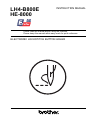
SAFETY INSTRUCTIONS
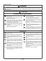
1. Safety indications and their meanings
This instruction manual and the indications and symbols that are used on the machine itself are provided in order to ensure
safe operation of this machine and to prevent accidents and injury to yourself or other people.
The meanings of these indications and symbols are given below.
Indications
DANGER
The instructions which follow this term indicate situations where failure to follow the instructions will almost certainly result in death or severe injury.
CAUTION
The instructions which follow this term indicate situations where failure to follow the instructions could cause injury when using the machine or physical damage to equipment and
surroundings
Symbols
………..…….. This symbol (
) indicates something that you should be careful of. The picture inside the triangle
indicates the nature of the caution that must be taken.
(For example, the symbol at left means “beware of injury”.)
………..…….. This symbol (
) indicates something that you must not do.
…..………….. This symbol ( ) indicates something that you must do. The picture inside the circle indicates the nature
of the thing that must be done.
(For example, the symbol at left means “you must make the ground connection”.)
HE-8000
i
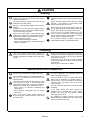
2. Notes on safety
DANGER
Wait at least 5 minutes after turning off the power switch and disconnecting the power cord from the wall outlet
before opening the face plate of the control box. Touching areas where high voltage are present can result in
severe injury.
CAUTION
Environmental requirements
Use the sewing machine in an area which is free
from sources of strong electrical noise such as highfrequency welders.
Sources of strong electrical noise may cause problems with correct operation.
Any fluctuations in the power supply voltage should
be within ±10% of the rated voltage for the machine.
Voltage fluctuations which are greater than this may
cause problems with correct operation.
The power supply capacity should be greater than
the requirements for the sewing machine’s electrical
consumption.
Insufficient power supply capacity may cause
problems with correct operation.
The ambient temperature should be within the range
of 5°C to 35°C during use.
Temperatures which are lower or higher than this
may cause problems with correct operation.
The relative humidity should be within the range of
45% to 85% during use, and no dew formation
should occur in any devices.
Excessively dry or humid environments and dew
formation may cause problems with correct operation.
Avoid exposure to direct sunlight during use.
Exposure to direct sunlight may cause problems with
correct operation.
In the event of an electrical storm, turn off the power
and disconnect the power cord from the wall outlet.
Lightning may cause problems with correct operation.
Installation
Machine installation should only be carried out by a
qualified technician.
Contact your Brother dealer or a qualified electrician
for any electrical work that may need to be done.
The sewing machine weighs more than 56 kg. The
installation should be carried out by two or more
people.
Do not connect the power cord until installation is
complete, otherwise the machine may operate if the
treadle is depressed by mistake, which could result
in injury.
Use both hands to hold the machine head when
tilting it back or returning it to its original position. If
only one hand is used, the weight of the machine
head may cause your hand to slip, and your hand
may get caught.
Be sure to connect the ground. If the ground connection is not secure, you run a high risk of receiving a
serious electric shock, and problems with correct
operation may also occur.
ii
HE-8000
All cords should be secured at least 25 mm away
from any moving parts. Furthermore, do not
excessively bend the cords or secure them too firmly
with staples, otherwise there is the danger that fire or
electric shocks could occur.
Install the belt covers to the machine head and
motor.
If using a work table which has casters, the casters
should be secured in such a way so that they cannot
move.
Be sure to wear protective goggles and gloves when
handling the lubricating oil and grease, so that they
do not get into your eyes or onto your skin, otherwise
inflammation can result.
Furthermore, do not drink the oil or eat the grease
under any circumstances, as they can cause vomiting
and diarrhoea.
Keep the oil out of the reach of children.
CAUTION
Sewing
This sewing machine should only be used by
operators who have received the necessary training
in safe use beforehand.
If using a work table which has casters, the casters
should be secured in such a way so that they cannot
move.
The sewing machine should not be used for any
applications other than sewing.
Attach all safety devices before using the sewing
machine. If the machine is used without these
devices attached, injury may result.
Be sure to wear protective goggles when using the
machine.
If goggles are not worn, there is the danger that if a
needle breaks, parts of the broken needle may enter
your eyes and injury may result.
Turn off the power switch at the following times,
otherwise the machine may operate if the treadle is
depressed by mistake, which could result in injury.
• When threading the needle
• When replacing the bobbin and needle
• When not using the machine and when leaving the
machine unattended
Do not touch any of the moving parts or press any
objects against the machine while sewing, as this may
result in personal injury or damage to the machine.
If an error occurs in machine operation, or if abnormal noises or smells are noticed, immediately
turn off the power switch. Then contact your nearest
Brother dealer or a qualified technician.
If the machine develops a problem, contact your
nearest Brother dealer or a qualified technician.
Cleaning
Turn off the power switch before carrying out
cleaning, otherwise the machine may operate if the
treadle is depressed by mistake, which could result
in injury.
Be sure to wear protective goggles and gloves when
handling the lubricating oil and grease, so that they
do not get into your eyes or onto your skin, otherwise
inflammation can result.
Furthermore, do not drink the oil or eat the grease
under any circumstances, as they can cause vomiting
and diarrhoea.
Keep the oil out of the reach of children.
Maintenance and inspection
Maintenance and inspection of the sewing machine
should only be carried out by a qualified technician.
Ask your Brother dealer or a qualified electrician to
carry out any maintenance and inspection of the
electrical system.
Turn off the power switch and disconnect the power
cord from the wall outlet at the following times,
otherwise the machine may operate if the treadle is
depressed by mistake, which could result in injury.
• When carrying out inspection, adjustment and
maintenance
• When replacing consumable parts such as the
rotary hook
Turn off the power switch before inserting or
removing the plug, otherwise damage to the control
box could result.
HE-8000
If the power switch needs to be left on when carrying
out some adjustment, be extremely careful to
observe all safety precautions.
Use both hands to hold the machine head when
tilting it back or returning it to its original position. If
only one hand is used, the weight of the machine
head may cause your hand to slip, and your hand
may get caught.
Use only the proper replacement parts as specified
by Brother.
If any safety devices have been removed, be
absolutely sure to re-install them to their original
positions and check that they operate correctly
before using the machine.
Any problems in machine operation which result
from unauthorized modifications to the machine will
not be covered by the warranty.
iii
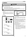
3. Warning labels
The following warning labels appear on the sewing machine.
Please follow the instructions on the labels at all times when using the machine. If the labels have been
removed or are difficult to read, please contact your nearest Brother dealer.
1
Hazardous voltage
will cause injury.
Hochspannung
verletzungsgefahr!
Turn off main
switch and wait 5
minutes before
opening this cover.
Bitte schalten sie den Eteindrel'interrupteur et
hauptschalter aus und attendre 5 minutes
warten sie 5 minuten, avantd' ouvrir le capot
bevor sie diese
abdeckung öffnen.
2
Moving parts
may cause injury.
Operate with safety devices.
Turn off main switch before
threading, changing bobbin
and needle, cleaning etc.
Un voltage non adapté
provoque des blessures.
Un voltaje inadecuado
puede provocar las
heridas.
Apagar el interruptor
principal y esperar 5
minutos antes de abrir
esta cubierta.
Safety device
Eye guard
Finger guard
Thread take-up cover
Belt cover
Belt cover plate, etc.
3
Be sure to connect the ground. If the ground connection is not secure, you run a high risk of
receiving a serious electric shock, and problems with correct operation may also occur.
4
Do not touch any of the cutter or press any objects against the machine while sewing, as
this may result in personal injury or damage to the machine.
5
Do not touch any of the fan or press any objects against the machine, as this may result in
personal injury or damage to the machine.
Thread take-up cover
Belt cover
Eye guard
4
3
5
Belt cover plate
Finger guard
2
3
1
2192Q
iv
HE-8000
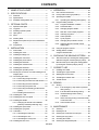
CONTENTS
1. NAME OF EACH PART.......................................1
2. SPECIFICATIONS .................................................2
2-1. Subclass ..................................................................2
2-2. Specifications ..........................................................2
2-3. Standard sewing pattern list ..................................3
5. OPERATION ..........................................................28
5-1. Part names and functions....................................28
5-2. Home position return (preparation).....................30
5-3. Operating the treadle ...........................................31
5-3-1. Operating the standing pedal (option) .....32
5-4. Program setting method ......................................33
3. OPTIONAL PARTS................................................4
5-4-1. Program initialization condition.................33
3-1. Special needle plate ...............................................4
5-4-2. Parameter table..........................................33
3-2. Leg parts ..................................................................4
5-4-3. Changing program details.........................43
3-3. Standing operation pedal.......................................4
5-4-4. Rear tack vector shape programs............47
3-4. Tape guard...............................................................5
5-4-5. Underlay programs....................................48
3-5. Ruler.........................................................................5
5-4-6. Cutter operation .........................................49
3-6. Auxiliary table ..........................................................5
5-4-7. Cycle program............................................50
3-7. Replacement parts set (for 70 mm buttonhole
length) ......................................................................6
5-4-8. Changing the production counter.............51
3-8. Programmer ............................................................6
5-4-9. Changing the lower thread counter
setting value................................................52
4. INSTALLATION .......................................................7
5-5. Using the program memos..................................53
4-2. Installing the motor..................................................9
5-6. Adding patterns created
using the BAS-PC/300.........................................53
4-3. Installing the flange nut...........................................9
6. CHECKING THE SEWING PATTERN ......55
4-1. Power table..............................................................7
4-4. Installing the control box.......................................10
4-5. Installing the power switch...................................11
6-1. Test feed mode (for checking the sewing pattern
without turning the machine pulley by hand).....55
4-7. Installing the machine head.................................12
6-2. Manual mode (for checking the sewing pattern
by turning the machine pulley by hand) .............56
4-8. Installing the head rest .........................................12
7. CORRECT USE ...................................................57
4-6. Installing the bed base..........................................11
4-9. Installing the operation panel...............................13
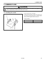
7-1. Installing the needle..............................................57
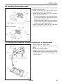
4-10. Routing the connector cord and installing the oil
stopper plate..........................................................13
7-2. Threading the upper thread.................................58
4-11. Connecting the cords ...........................................14
7-4. Threading the bobbin case..................................60
4-11-1. Connecting the ground wire......................14
4-11-2. Connecting the machine head harness...14
4-11-3. Connecting the motor harness .................15
4-11-4. Connecting the power cord.......................16
7-3. Winding the lower thread.....................................59
7-5. Thread tension......................................................61
8. SEWING ...................................................................63
8-1. Sewing...................................................................63
8-1-1. If the emergency stop switch is pressed
during sewing .............................................64
4-11-5. Connecting the standing pedal harness
(option).........................................................17
8-1-2. If the thread breaks during sewing...........65
4-11-6. Installing the transformer ...........................18
8-1-3. Thread breakage before sewing
is finished ....................................................66
4-12. Installing the V-belt................................................20
4-13. Installing the belt cover plate ...............................21
8-1-4. When resuming sewing in test feed mode
or manual mode.........................................67
4-14. Installing the treadle..............................................22
4-14-1. Changing the treadle unit installation
position (horizontal positioning only) ........23
8-1-5. Lower thread counter ................................67
4-15. Installing the spool stand......................................23
9. MAINTENANCE ...................................................68
4-16. Installing the eye guard ........................................24
9-1. Cleaning.................................................................68
4-17. Lubrication .............................................................25
9-2. Draining the oil ......................................................69
4-17-1. Lubricating the bed base...........................25
9-3. Cleaning the control box air inlet port.................69
4-17-2. Lubricating the arm ....................................26
9-4. Cleaning the eye guard........................................69
4-17-3. Lubricating the rotary hook........................26
9-5. Checking the needle ............................................70
4-18. Installing the belt cover.........................................27
9-6. Cleaning the length feed plate ............................70
HE-8000
10. STANDARD ADJUSTMENTS........................71
10-1. Needle bar height..................................................71
10-2. Needle and hook timing adjustment ...................72
10-3. Adjusting the clearance between needle and
hook point ..............................................................72
10-4. Adjusting the inner rotary hook and rotary hook
holder overlap........................................................73
10-5. Adjusting the work clamp pressure.....................73
10-6. Adjusting the knife installation .............................73
10-7. Adjusting the upper thread trimming...................74
10-7-1. Adjusting the installation height of the
upper thread scissors ................................74
10-7-2. Adjusting the upper thread scissors
opening timing ............................................75
10-8. Adjusting the lower thread clamp timing ............76
10-9. Adjusting the bobbin presser...............................76
10-10. Adjusting the needle up stop position ...............76
11. CHANGING FUNCTIONS USING THE
MEMORY SWITCHES ......................................77
12. PROGRAM INITIALIZATION ..........................79
12-1. Initializing all programs.........................................79
12-2. Initializing a single program .................................79
13. CHANGING FUNCTIONS USING THE
DIP SWITCHES ....................................................80
13-1. Panel DIP switches...............................................80
13-2. Control circuit board DIP switches ......................82
14. GAUGE PARTS LIST .........................................84
15. ERROR CODE TABLE ......................................89
16. TROUBLESHOOTING ......................................91
HE-8000
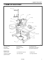
1. NAME OF EACH PART
1. NAME OF EACH PART
(7)
(11)
(12)
(8)
(6)
(10)
(9)
(3)
(14)
(13)
(5)
(15) (16)
(1)
(2)
(4)
2034Q
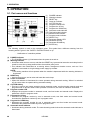
(1) Power switch
(2) Control box
(3) Operation panel
(4) Treadle
(5) AC servo motor
(6) Emergency stop switch
(7) Spool stand
(8) Pulley
(9) Tension release lever
Safety devices
(10) Eye guard
(11) Thread take-up cover
(12) Belt cover
(13) Belt cover plate
(14) Finger guard
(15) Finger protector
(16) Belt retainer
HE-8000
1
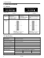
2. SPECIFICATIONS
2. SPECIFICATIONS
2-1. Subclass
Subclass
Subclass
Main use
Subclass
-2
-3
-5
Buttonholes for
clothing such as dress
shirts, blouses, work clothes
and women's clothes
Buttonholes for
knitted garments such as
knitted underwear, sweaters,
cardigans and jerseys
Buttonholes for clothing such
as work clothes and women’s
clothes
Belt holes for child seats, etc.
A
Buttonhole
size
B
A
2193Q
C
D
B
A: Max.6 mm
B: Max. zigzag stitch length 39 mm
C: Length of knife 4 – 32 mm
D: Max. buttonhole length 40 mm
2193Q
C
D
A: Max.6 mm
B: Max. zigzag stitch length 69 mm
C: Length of knife 4 – 32 mm
D: Max. buttonhole length 70 mm
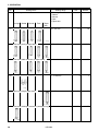
2-2. Specifications
Max. sewing speed
4,000 rpm
Zigzag mechanism
Pulse motor driven mechanism
Feed mechanism
Pulse motor driven mechanism
Work clamp lifter mechanism
Pulse motor driven mechanism
Height of work clamp
13 mm (adjustable)
Knife mechanism
Double position solenoid
Lower thread holding device
Standard equipment
Bobbin presser
Standard equipment
Standard sewing pattern
21
Memory pattern
90
Max. number of stitch
700 stitches / program (Overall cycle program stitch no. 3,000 stitches)
Needle
Subclass -2
Subclass -3
Subclass -5
Schmetz Nm134#90
Schmetz Nm134#75
Schmetz Nm134#90
Data storage method
P-ROM (Custom made pattern can be added by BAS-PC/300)
Power supply
Single phase 110 V, 220 V, 230 V, 240 V, Three phase 220 V, 380 V, 400 V, 415 V 600 VA
2
HE-8000
2. SPECIFICATIONS
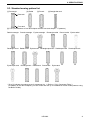
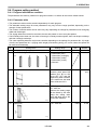
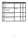
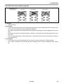
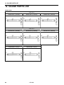
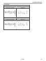
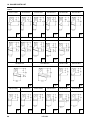
2-3. Standard sewing pattern list
[1] Rectangle
[2] Radial
[3] Round
[4] Straight bar tack
Rear tack
Front tack
[0] Free (Combinations of rear tack shapes and the front tack shapes - 17 patterns)
Radial-rectangle Round-rectangle Eyelet-rectangle Rectangle-radial Round-radial Eyelet-radial
Rectangle-round Radial-round Eyelet-round Rectangle-taper tack Radial-taper tack Round-taper tack
Eyelet-taper tack
Rectangle-tack Radial-tack Round-tack
Eyelet-tack
* [0] to [4] indicate the setting range for parameter No. 1. (Refer to "5-4-2. Parameter Table".)
(In addition to the above shapes, you can create and use up to 9 additional custom made patterns using
the BAS-PC/300.)
HE-8000
3
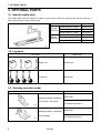
3. OPTIONAL PARTS
3. OPTIONAL PARTS
3-1. Special needle plate
This needle plate uses the elasticity of rubber to prevent the cutter from getting stuck and not returning. It
also helps to keep the cutter blade sharp.
Parts name
General
materials
Knitted
materials
Parts code
Needle plate set 1.2RB
S51361-001
Needle plate set 1.4RB
S51362-001
Needle plate set 1.6RB
S51363-001
Needle plate set 1.2RB-3
S51364-001
Needle plate set 1.4RB-3
S51365-001
Needle plate set 1.6RB-3
S51366-001
2037Q
3-2. Leg parts
Parts name
Parts code
Spacer set
183504-109
Caster set
183501-001
2038Q
2039Q
3-3. Standing operation pedal
Parts name
Parts code
Standing operation 2 pedal #6
(Two pedals + kick pedal)
J80081-040
S47750-000 (Harness)
2040Q
Standing operation 3 pedal #40
(Three pedals)
2041Q
4
HE-8000
J80380-040
S47750-000 (Harness)
3. OPTIONAL PARTS
3-4. Tape guard
Tape guard winder assy
S50346-001
Tape winder bracket assy
143767-102
Tape guard assy
S51896-001
2042Q
3-5. Ruler
Ruler assy 800E
S50350-001
Ruler assy
S50477-001
2043Q
2044Q
3-6. Auxiliary table
Sub-table assembly
S53996-001
2045Q
HE-8000
5
3. OPTIONAL PARTS
3-7. Replacement parts set (for 70 mm buttonhole length)
Replacement parts set –70
S54501-001
2046Q
3-8. Programmer
You can use the icon keys to retrieve parameters at a single touch, and to display them as icons on the LED
screen so that the settings can be changed easily. It allows you to easily transfer data between different
sewing machines.
Parts name
Parts code
Programmer set A1
(Japanese-language
Instruction Manual)
S58988-001
Programmer set A2
(English-language
Instruction Manual)
S58989-001
* The only difference between Sets A1 and A2 is the
Instruction Manual.
2047Q
6
HE-8000
4. INSTALLATION
4. INSTALLATION
CAUTION
Machine installation should only be carried
out by a qualified technician.
Contact your Brother dealer or a qualified
electrician for any electrical work that may
need to be done.
The sewing machine head weighs more
than 56 kg. The installation should be carried out by two or more people.
Do not connect the power cord until installation is complete, otherwise the machine may operate if the treadle is depressed by mistake, which could result in
injury.
All cords should be secured at least 25 mm
away from any moving parts. Furthermore, do not excessively bend the cords or
secure them too firmly with staples, otherwise there is the danger that fire or electric
shocks could occur.
Be sure to connect the ground. If the
ground connection is not secure, you run a
high risk of receiving a serious electric
shock, and problems with correct operation may also occur.
Install the belt covers to the machine head
and motor.
Use both hands to hold the machine head
when tilting it back or returning it to its
original position. If only one hand is used,
the weight of the machine head may cause
your hand to slip, and your hand may get
caught.
4-1. Power table
Use the power table which has been specially designed for each sewing machines.
Positioning
Table/legs assembly
Model code
Vertical
127-H80-200-01
Horizontal
127-H80-201-01
If using a commercially-available table, process it as shown in the following illustration.
NOTE:
The thickness of the table should be at least 40 mm, and it should be strong enough to bear the weight and
vibration of the sewing machine.
HE-8000
7
4. INSTALLATION
1) Vertical positioning
2194Q
2) Horizontal positioning
2195Q
8
HE-8000
4. INSTALLATION
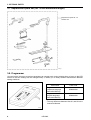
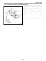
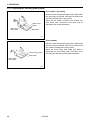
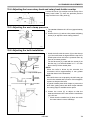
4-2. Installing the motor
Install the motor (1) with the three bolts (2), flat
washers (3), spring washers (4) and nuts (5).
(2)
(1)
(3)
(4)
(5)
2050Q
4-3. Installing the flange nut
Install the four flange nuts (1) to the underside of the
work table.
NOTE:
When the machine head is positioned horizontally,
some flange nut installation locations may be
inaccessible after the control box has been installed. Be sure to install the flange nuts correctly
so that they are not at an angle.
(1)
2051Q
HE-8000
9
4. INSTALLATION
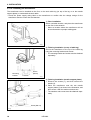
4-4. Installing the control box
(4)
(5)
(6)
(7)
(8)
2 mm
(9)
(1)
(2)
(1)
(3)
2052Q
1. Remove the 12 screws (1), and then open the covers (main P.C. board mounting plate (2) and sub P.C.
mounting plate (3)).
NOTE:
When opening the cover, hold it securely so that it does not fall down.
2. Install the control box with the bolts (4), cushions (5), cushion collars (6), rubber collars (7), flat washers
(8) and nuts (9) as shown in the illustration. At this time, leave a gap of approximately 2 mm between the
work table and the top of the box.
3. Close the covers (main P.C. board mounting plate (2) and sub P.C. mounting plate (3)), and provisionally
tighten them with the screws (1). (They will be opened again when the cords are connected.)
10
HE-8000
4. INSTALLATION
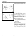
4-5. Installing the power switch
1. Install the power switch (1) with the two screws (2).
2. Secure the power switch (1) cord and the motor
(4) cord with the six staples (3).
(1)
(4)
(2)
(3)
2053Q
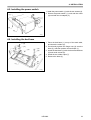
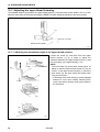
4-6. Installing the bed base
1. Place the bed base (1) on top of the work table,
and insert the collars (2).
2. Provisionally tighten the flange nuts (4) onto the
bolts (3), and then position the bed base (1).
3. Install the bed base (1) with the three flat washers
(5) and wood screws (6).
4. Install the two rubber caps (7).
5. Remove the bolts (3).
(3)
(7)
(6)
(5)
(7)
(6)
(5)
(2)
(4)
(3)
(2)
(4)
(1)
(6)
(5)
2054Q
HE-8000
11
4. INSTALLATION
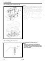
4-7. Installing the machine head
2055Q
(5)
(4)
(2)
(1)
NOTE:
The bed base (1) is made from plastic, so be careful
not to hit it with the machine head when placing the
machine head on top of it.
1. Open the hinges (2) as shown in the illustration.
Then place the machine head gently on top of the
bed base (1), while being careful not to clamp the
cords (3).
2. Install the machine head with the spring washers
(4) and bolts (5).
NOTE:
Make sure that the felt support (6) do not touch the
bed base (1).
(3)
(6)
(1)
2056Q
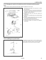
4-8. Installing the head rest
Tap the head rest (1) into the table hole.
NOTE:
Tap the head rest securely into the table hole.
If the head rest is not pushed in as far as it will go,
the machine head will not be sufficiently stable
when it is tilted back.
(1)
1240Q
12
HE-8000
4. INSTALLATION
4-9. Installing the operation panel
2057Q
Top of
of work
work table
table
Top
(1)
(4)
(3)
(2)
(5)
Table
(6)
Bottom of work table
Bottom of work table
The operation panel can be installed to either the top
or bottom of the work table.
1. Install the rear frame (1) to the work table (top or
bottom) with the four wood screws (2).
2. Install the front frame assy (3) to the rear frame
(1) with the four screws (4).
* The vertical orientation of the front frame assy
(3) is the same whether it is installed to the top
or the bottom of the work table.
* Pull the harnesses such as the ground harness
out of the way so that the operation panel side
cover (5) can be opened and closed.
3. Insert the connector cord (6) into the control box
through the hole at the side of the box.
(4)
(1)
(3)
(6)
Table
(2)
(5)
2058Q
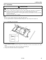
4-10. Routing the connector cord and installing the oil stopper plate
2059Q
(3)
1. Gently tilt back the machine head.
2. Pass the cords (1) through the hole in the work
table.
3. Install the oil stopper plate (2).
4. Move the connector cord (1) so that it will not be
clamped by the machine head and the bed base
(3), and then return the machine head to its
original position.
(1)
(2)
2060Q
HE-8000
13
4. INSTALLATION
4-11. Connecting the cords
CAUTION
Be sure to connect the ground. If the ground connection is not secure, you run a high risk of
receiving a serious electric shock, and problems with correct operation may also occur.
NOTE:
The harness is connected in the same way regardless of whether the machine head is positioned
horizontally or vertically.
4-11-1. Connecting the ground wire
(3)
(5)
Grounding
mark
(2)
(8)
(4)
(1)
(2)
(6)
(7)
Grounding
mark
1. Remove the 12 screws (1), and then open the
covers (2) on both sides of the control box.
NOTE:
When opening the covers (2), hold them securely
so that they do not fall down.
2. Insert the panel harness(3) into the control box.
3. Connect the ground wire (4) which is protruding out
from the hole in the control box to the leg (5).
Connect the ground wire (6) coming from the
machine head to the ground wire (7) inside the
control box. Connect the ground wire in the middle
of the panel harness to the ground wire (8) inside
the control box. (Grounding marks are displayed on
the machine head and inside the control box.)
* If the shape of the grounding screw in the leg (5)
requires a different ground wire to be connected,
re-place the ground wire with the accessory
ground wire.
2061Q
NOTE:
If the ground wires are not connected, incorrect
operation may result.
If the grounding point has been painted over,
remove the paint coating before connecting the
ground wire.
4-11-2. Connecting the machine head harness
(1)
1. Insert the machine head harness (1) into the
control box.
2. Tilt back the machine head.
3. Pull the harness (1) through the cord clamp (2) at
the top of the control box. This cord clamp is not
used when the machine head is positioned
horizontally.
(2)
2062Q
14
HE-8000
4. INSTALLATION
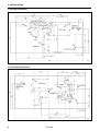
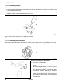
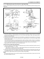
4-11-3. Connecting the motor harness
1. Pass the motor harness (1) through the rubber
cushion (2).
2. Connect the connectors (3).
3. Secure the motor harness (1) with staples.
(3)
(1)
(2)
2063Q
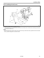
4. Connect the connectors of the feed motor harness
(4) and the presser foot motor harness (5). In the
same way, connect the connectors for the cutter
solenoid harness (6), the DC fan motor harness (7)
and the cutter home position sensor harness (8).
(8)
(7)
Mark
(4) Feed motor<5-pin>(White)
S2
P2<FDPM>
Presser foot motor<5-pin>
(Blue)
S5
P5<FTPM>
S8
P8<CUTTER>
(5)
(6) Cutter solenoid<6-pin>
(7) Fan<3-pin>
Cutter home position sensor
(8)
<12-pin>
(6)
(5)
Sub P.C.board
indication
Harness
S7
P10<FAN1>
P7<OPSEN2>
(4)
2064Q
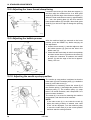
5. Connect the connectors of the zigzag motor
harness (9) and the tension release solenoid
harness (10).
Take note of how these two harnesses are routed
through the control box so as not to confuse them
with any of the other harnesses.
Harness
(9) Zigzag motor <6-pin>
(10)
Tension release solenoid
<6-pin>
Mark
Main P.C.board
indication
M16
P16<NPM >
M19
P19<OPSOL>
(9)
(10)
2065Q
HE-8000
15
4. INSTALLATION
6. Connect the connectors of the synchronizer
harness (11), the home position sensor harness
(12) and the emergency stop switch harness (13).
Harness
(13)
(12)
Mark
Main P.C.board
indication
(11) Synchronizer<5-pin>
M3
P3<SYNC>
Home position sensor
(12)
<12-pin>
M11
P11<ORG>
(13) Emergency stop<11-pin>
M10
P10<HEAD>
(11)
2066Q
7. Secure the harnesses inside the control box using cord clamps.
NOTE:
* Make sure that the harnesses do not come into contact with P.C. board components or with the main P.C.
board heat sink or the sub-P.C. board heat sink.
• Use the cord clamps at the top of the control box to adjust the harnesses so that they are not loose
inside the control box, particularly when using the work table with the machine head positioned vertically.
8. Gently return the machine head to its original position.
* Check that the harnesses do not touch the belt.
9. Close the covers on both sides of the control box, and tighten the 12 screws.
4-11-4. Connecting the power cord
1. Attach an appropriate plug to the power cord (1).
(The green and yellow wire is the ground wire.)
2. Insert the plug into a properly-grounded AC
power supply.
NOTE:
Do not use extension cord, otherwise machine
operation problems may result.
Do not connect a power supply which is not of the
rated voltage, otherwise machine operation problems may result.
(1)
2196Q
16
HE-8000
4. INSTALLATION
4-11-5. Connecting the standing pedal harness (option)
(2)
(5)
(4)
(6)
(1)
(3)
1. Pass the marked tube of the relay harness (1)
into the control box through the hole (2) in the
control box.
2. Connect the relay harness (1) to connector P9 on
the main circuit board (3).
3. Remove the screw (4) which is securing the
ground wires, and then add the ground wire (5) of
the relay harness (1) and re-tighten the screw (4).
(The green-and-yellow wire is the ground wire.)
4. Connect the standing pedal harness (6) to the
relay harness (1).
* Connect the standing pedal harness (6) and the
relay harness (1) inside the control box.
2068Q
HE-8000
17
4. INSTALLATION
4-11-6. Installing the transformer
The transformer can be installed on the floor, on the work table leg (on top of the leg or on the treadle
support plates) or underneath the work table.
* Check the power supply rating label on the transformer to confirm that the voltage ratings for the
transformer and the control box are identical.
1) Floor installation
Select a suitable location, and place the transformer
on the floor in that location.
* Select a location where the transformer will not
be an obstruction to people walking past.
2069Q
2070Q
Mounting
bracket
2) Table leg installation (on top of table leg)
Secure the transformer to the top of the table leg
using the mounting bracket and screws.
* The mounting bracket and screws must be obtained
separately.
Screw
(M5×8)
112.5mm
2071Q
2073Q
2072Q
(2)
(2)
(3)
3) Table leg installation (treadle support plates)
1. Remove the screws (1), and then remove the
handle (2).
2. Place the transformer onto the two treadle
support plates (3) as shown in the illustration, and
then secure it with the washers and screws.
* The washers and screws must be obtained separately.
(1)
(2)
(3)
Washer
Screw (M6×14)
2074Q
18
HE-8000
4. INSTALLATION
2075Q
4) Installation underneath the work table
* Standard BROTHER work tables are provided
with installation holes for use in installing the
transformer.
1. Remove the screws (1), and then remove the
handle (2).
2. Use the bolts (4), flat washers (5), spring washers
(6) and nuts (7) to install the transformer as
shown in the illustration, while leaving a gap of 2
mm between the work table and the cushion
collars (3).
Use the bolts (4), flat washers (5), spring washers
(6), nuts (7) and cushion brackets (3) which are
included.
Work table hole
positions
(2)
(4)
(1)
2076Q
(3)
(5)
(6)
(7)
(3)
2 mm
(5)
(6)
(7)
2077Q
2078Q
<Connecting the cords>
2079Q
(3)
(2)
(4)
(6)
(5)
(1)
1. Loosen the screws (1), and then remove the
transformer cover (2).
2. Connect the control box connector (3) to the
transformer connector (4).
3. Secure the connected cords with the cord holder
(5) and the screw (6), and place them inside the
transformer cover (2). Install the transformer
cover (2) with the screws (1).
4. Secure the cords to the work table using staples.
(6)
(5)
(1)
2080Q
HE-8000
19
4. INSTALLATION
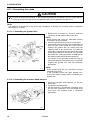
4-12. Installing the V-belt
1. Remove the screw (1), and then remove the
motor belt cover (2).
(2)
(1)
(1)
2081Q
2082Q
(3)
10 – 14 mm
(4)
(5)
(3)
(2)
2. Gently tilt back the machine head, and then place
the V-belt (3) into the V grooves in the machine
head pulley and the motor pulley.
3. Turn the two nuts (4) to adjust so that there is 10 14 mm of deflection in the V-belt (3) when it is
pressed at the midway point with a force of 5 N.
NOTE:
If the V-belt tension is too loose, or if the V-belt is
stretched, the following problems could occur.
a. The stopping position may shift,
b. The needle bar may drift when the machine
stops,
c. An extra stitch may be sewing when the
machine stops,
d. An abnormal noise may be heard due to V-belt
slipping, and
e. The V-belt may become too loose and contact
with the cover.
If any such problems occur, adjust by following the
procedure described above.
4. Secure the motor belt cover (2) and the auxiliary
motor belt cover (5) with the four screws (1) as
shown in the illustration so that they do not touch
the V-belt (3).
(1)
(1)
2083Q
20
HE-8000
4. INSTALLATION
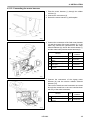
Adjusting the belt retainer
1. Loosen the screw (1).
2. Align the boss of the belt retainer (2) with the
mark (3).
3. Tighten the screw (1).
Tighten the screw (1).
(2)
(4)
Adjusting the finger protector
1. Loosen the screw (4).
2. Align the center of the screw (4) with the mark (5).
3. After adjusting, tighten the screw (4).
(1)
(5)
(3)
2084Q
4-13. Installing the belt cover plate
NOTE:
If the machine head is positioned horizontally, there is no need to install the belt cover plate.
(1)
(1)
(3)
(2)
(2)
3 mm or more
2085Q
2086Q
1. Set the belt cover plate (1) so that there is a gap of 3 mm or more in the longer motor direction. The belt
cover plate (1) should not project out from the edge of the work table.
2. Install the belt cover (1) with the wood screws (3) so that it does not touch the motor belt cover (2).
HE-8000
21
4. INSTALLATION
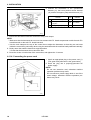
4-14. Installing the treadle
Install the connecting rod (1) to the treadle lever (2)
with the nut (3).
(2)
(3)
(1)
2087Q
(4)
(3)
Fig. A
(1)
Adjusting the treadle pressure
If the machine starts running when your foot is
simply resting on the treadle, or if the treadle
pressure is too weak, adjust the position (a to c) at
which the treadle spring (1) is hooked onto the
treadle lever (2).
The treadle pressure will increase from position a to
position c.
Fig. B
(6)
(2)
(5)
a b c
(6)
2088Q
Adjusting the treadle return pressure
1. Loosen the nut (3) and turn the bolt (4). The
treadle return pressure becomes heavier as the
bolt (4) is tightened, and becomes lighter as the
bolt (4) is loosened.
2. Tighten the nut (3).
Adjusting the treadle stroke
Remove the nut (5), and then move connecting rod
joint (6) from the position in figure A to the position in
figure B. The treadle stroke will increase by approx.
1.25 times.
* This adjustment will also affect the treadle
pressure and the treadle return pressure, so these
settings should be readjusted if necessary.
22
HE-8000
4. INSTALLATION
4-14-1.Changing the treadle unit installation position (horizontal positioning only)
NOTE:
If the machine head is positioned horizontally, install the treadle unit to the motor.
2089Q
(2)
(1)
(3)
1. Disconnect the treadle unit connector (1) inside
the control box.
2. Remove the screw (2), and then disconnect the
ground wire. After disconnecting the ground wire,
re-tighten just the screw (2).
3. Remove the screw (3), and then remove the
treadle unit.
4. Install the V cord bushing (5) to the treadle setting
plate (4).
5. Install the treadle setting plate (4) and the treadle
unit to the motor with the screw (3).
6. Install the ground wire with the screw (6).
7. Connect the treadle unit connector (1) inside the
control box.
2090Q
(3)
(5)
(6)
(4)
(3)
2091Q
4-15. Installing the spool stand
Assemble the spool stand (1) while referring to the
spool stand instruction manual, and then install the
spool stand (1) at the left side of the work table.
(1)
1246Q
HE-8000
23
4. INSTALLATION
4-16. Installing the eye guard
CAUTION
Attach all safety devices before using the sewing machine.
If the machine is used without these devices attached, injury may result.
(5)
(4)
(3)
(2)
(2)(3)
(1)
(1)
[Vertical positioning]
[Horizontal positioning]
2093Q
2092Q
Install the eye guard (1) with the screw (2) and flat washer (3).
NOTE:
If the machine head is positioned horizontally, install the eye guard support (4) to the machine head with
the screw (5), and then install the eye guard (1).
24
HE-8000
4. INSTALLATION
4-17. Lubrication
CAUTION
Turn off the power switch before carrying out lubricating, otherwise the machine may operate if the
treadle is depressed by mistake, which could result in injury.
Be sure to wear protective goggles and gloves when handling the lubricating oil and grease, so
that they do not get into your eyes or onto your skin, otherwise inflammation can result.
Furthermore, do not drink the oil or eat the grease under any circumstances, as they can cause
vomiting and diarrhoea.
Keep the oil out of the reach of children.
NOTE:
Be sure to let the machine operate for a while after adding the oil.
Use only specified Brother oil (Nisseki Mitsubishi Sewing Lube 10N; VG10) for the machine oil.
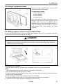
4-17-1. Lubricating the bed base
(1)
2094Q
1. Set the magnet (1) in place.
2. Gently tilt back the machine head and slowly pour in lubricating oil until the oil level reaches the “HIGH”
mark.
If the oil level drops below the “LOW” mark, add more lubricating oil.
3. Gently return the machine head to its original position.
HE-8000
25
4. INSTALLATION
4-17-2. Lubricating the arm
NOTE:
* Be sure to lubricate the arm when first installing the machine and when the machine has not been used
for an extended period of time.
* When using the machine, check that the oil is visible through the oil cap (2). If it cannot be seen,
problems such as seizure of the mechanism may occur.
(1)
(2)
2095Q
Apply 5-6 drops of oil to the oil inlet (1) at the top of the arm.
4-17-3. Lubricating the rotary hook
When first installing the machine and when the machine has not been used for an extended period of time,
remove the bobbin and add 2-3 drops of oil to the rotary hook race (1) before sewing.
(1)
2096Q
Rotary hook lubrication adjustment
More
Less
(2)
2097Q
26
1. Remove the rubber stopper.
2. Turn the adjusting screw to adjust the lubrication
amount.
* Adjust so that approximately 10 drops of oil are
released when the sewing machine is run at a
speed of 4,000 rpm for three cycles to sew about
114 stitches. Use Kraft paper (2) or similar to
catch the oil drops. As a guide, the optimum
position can be obtained if the adjusting screw is
tightened as much as possible and then loosened
about two turns.
HE-8000
4. INSTALLATION
4-18. Installing the belt cover
(2)
(3)
(1)
(5)
(4)
2098Q
1. Attach the rubber cap (2) to the belt cover (1).
2. Insert the belt cover (1) in the direction of the arrow, and then secure it with the two screws (3), the screw
(4) and the flat washer (5).
NOTE:
When tilting back the machine head, remove the screws (3), loosen the screw (4) and then remove the belt
cover (1) before tilting back the machine head.
HE-8000
27
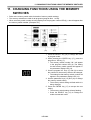
5. OPERATION
5. OPERATION
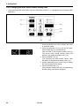
5-1. Part names and functions
(3)
(9)
(6)
(10)
(1)
(2)
(14)
(11)
(7)
(12)
(8)
(4)
(15)
(16)
(3)
(5)
(13)
(17)
2099Q
(1)
(2)
(3)
(4)
(5)
(6)
(7)
(8)
(9)
(10)
(11)
(12)
(13)
(14)
(15)
(16)
(17)
POWER indicator
Warning indicator
RESET key
Cutter on indicator
CUTTER ON key
Program number LED
Program No. UP key
Program No. DOWN key
Automatic mode indicator
Test feed mode indicator
Manual mode indicator
Program mode indicator
SELECT key
Parameter display LED
Parameter UP key
Parameter DOWN key
ENTER key
NOTE:
The following symbol is used on the operation panel. This symbol has a different meaning from the
meaning which is given in the "SAFETY INSTRUCTIONS" on p.i.
· · · · Notification of a machine problem
(1) POWER indicator
• The POWER indicator (1) illuminates when the power is turned on.
(2) Warning indicator
• Illuminates when an error occurs, and after the RESET key is pressed to lower the work clamp but the
needle is not at the up stop position when the machine pulley turns.
• This indicator also illuminates as a warning when a dangerous situation occurs, such as if the
machine is connected to a high-voltage power supply by mistake.
NOTE:
• The sewing machine will not operate when the treadle is depressed while the warning indicator is
illuminated.
(3) RESET key
• Used to reset errors, and to raise and lower the work clamp.
(4) Cutter on indicator
• When this indicator is illuminated, the cutter operates during automatic sewing. When it is switched
off, the cutter does not operate during automatic sewing.
(5) CUTTER ON key
• This key is used to turn cutter operation during automatic mode, test feed mode, manual mode and
program mode on and off. When cutter operation is turned on, the cutter on indicator illuminates.
(6) Program number LED
• Displays the program number in automatic mode, test feed mode and manual mode. Displays the
parameter number in program mode.
(7) Program No. UP key
• Increases the program number by one in automatic mode, test feed mode and manual mode.
Increases the parameter number by one in program mode.
(8) Program No. DOWN key
• Decreases the program number by one in automatic mode, test feed mode and manual mode.
Decreases the parameter number by one in program mode.
(9) Automatic mode indicator
• Illuminates during automatic mode. The normal sewing mode is when the automatic mode indicator is
illuminated.
28
HE-8000
5. OPERATION
(10) Test feed mode indicator
• Illuminates during test feed mode. This mode is used to check the number of stitches in the sewing
pattern.
(11) Manual mode indicator
• Illuminates during manual mode. In this mode, a single stitch is sewn each time the machine pulley is
turned manually.
(12) Program mode indicator
• This mode is used to set the various parameters for sewing programs. If the program no. UP key or
ENTER key is pressed while parameter setting is being carried out, the mode changes to memory
switch setting mode. If the program no. UP key or ENTER key is pressed during memory switch
setting mode, the mode changes to cycle program setting mode.
(13) SELECT key
• This key is used to change between automatic mode, test feed mode, manual mode and program
mode.
(14) Parameter display LED
• Displays the production counter, lower thread counter and parameter details, and also displays error
codes.
(15) Parameter UP key
• Used to increase parameter values.
(16) Parameter DOWN key
• Used to decrease parameter values.
(17) ENTER key
• Used to accept a program number during automatic mode. Used to accept changed values for
parameter settings during program mode.
• If the sewing machine is started while the ENTER key is being pressed during automatic mode, only
the sewing machine will operate and the mode will change to lower thread winding mode.
HE-8000
29
5. OPERATION
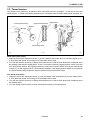
5-2. Home position return (preparation)
Before starting home position return......
Check that the needle bar is at its highest position.
Turn the machine pulley so that the index mark (18)
on the pulley is between the marks (19) on the belt
cover.
If the machine is started while the index mark (18) is
not between these two marks (19), error message
"E-02" will be displayed. At this time, the error will be
cleared if you turn the machine pulley to set the
needle to the needle up stop position.
(18)
(19)
0118Q
NOTE:
When transporting and installing the sewing machine, the thread trimming mechanism may move so that
the machine pulley cannot be turned. In such cases, do not force the pulley to turn. Move the thread
trimming mechanism to the home position, or turn the machine pulley in the reverse direction to set the
needle to the needle up stop position.
2100Q
(1)
1. Turn on the power.
• The POWER indicator (1) will illuminate and the
model number will appear for one second in the
parameter display LED (14).
(14)
• After this, "--" will appear in the program
number LED (6) and "----" will appear in the
parameter display LED (14).
(6)
(14)
2101Q
C
2102Q
30
2. Depress the treadle to the 2nd step [C].
• The sewing machine will move to the home
position, and the work clamp will move to the
neutral position.
• After the home position has been reached, the
mode will change to the mode which was active
when the power was turned off (automatic/test
feed/manual/program).
HE-8000
5. OPERATION
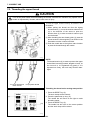
5-3. Operating the treadle
2103Q
2104Q
A
1. When the treadle is not depressed [A], the work
clamp is at the neutral position.
* The work clamp lifter height at the neutral position
can be changed to between 1 mm and 13 mm
using memory switch No. 05. [Figure 1]
Fig. 1
2. When the treadle is depressed to the 1st step [B],
the work clamp drops.
* When memory switch No. 06. is off, the work
clamp drops to its lowest position. [Figure 2]
* If memory switch No. 06. is set to between 0.1-8
mm, the work clamp drops to the height which
has been set. This is useful for positioning the
material. (Soft press) [Figure 3]
B
Fig. 2
2105Q
3. When the treadle is depressed to the 2nd step [C],
the machine starts sewing.
Fig. 3
C
2102Q
D
4. When the treadle is depressed backward to the
position in [D], the work clamp rises to the height
which has been set using memory switch No. 04.
This is useful for inserting and removing the
material.
2107Q
2106Q
After sewing
A
2107Q
D
Insertion and removal of
the material
B
2104Q
C
2105Q
Normal position
2197Q
Buttonhole positioning
HE-8000
2102Q
Sewing
31
5. OPERATION
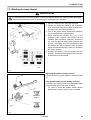
5-3-1. Operating the standing pedal (option)
[Two pedals + kick pedal]
When the work clamp pedal (right side) is depressed,
the work clamp is lowered, and when the start pedal
(left side) is depressed, sewing starts.
When the kick pedal is kicked to the outside, the
work clamp rises. (functions in the same way as
depressing the treadle backward.)
Work clamp
pedal
Work clamp
lifter pedal
Start pedal
2109Q
[Three pedals]
When the work clamp pedal (right side) is depressed,
the work clamp is lowered, and when the start pedal
(the middle) is depressed, sewing starts.
When the work clamp lifter pedal (left side) is
depressed, the work clamp rises. (Functions in the
same way as depressing the treadle backward.)
Work clamp pedal
Start pedal
Work clamp
lifter pedal
2110Q
32
HE-8000
5. OPERATION
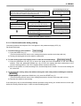
5-4. Program setting method
5-4-1. Program initialization condition
The parameters and memory switches for program numbers 1 to 90 are all set to their default values.
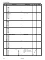
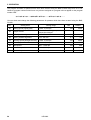
5-4-2. Parameter table
• The parameter values can be stored independently for each program.
• The allowable setting range for some parameters may vary from the range specified, depending on the
settings of other parameters.
• The number of stitches which can be sewn may vary depending on settings for parameters such as zigzag
width and feed length.
• The zigzag width ratio cannot be set when the rear tack pattern is set to an eyelet pattern.
• If all underlays have been set, the order of sewing is underlays sewn together, then saw-shape underlays
and then rectangle underlays.
* The cutter operating distance may become smaller depending on the settings for parameter No. 2 (Length
of knife) and parameter No. 3 (zigzag stitch length [multi-working knife]), so in such cases the speed will
be reduced automatically.
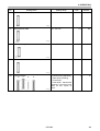
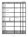
No.
Setting items
Setting range
00
Sewing speed (zigzag part)
1,000 – 4,000 rpm
01
Buttonhole/Straight bar tack
0:
1:
2:
0: Buttonhole (free)
1: Buttonhole (rectangle)
2: Buttonhole (radial)
3: Buttonhole (round)
4: Bar tack
3:
4:
Unit
Default
100
3,600
1
1437Q
02
Length of knife
4.0 - 32.0 mm
However, when panel DIP
switches B-3, B-4 or B-5
are at OFF, OFF and ON
respectively when initialization is carried out, the initial
value will be set to 6.0.
0.1
13.0
(6.0)
OFF: Single working knife
4.0 - 69.0 mm
However, the setting range
will be limited by the work
clamp size setting value
which has been set by the
B panel DIP switches.
0.1
OFF
0.025
0.350
1438Q
03
Zigzag stitch length (multi-working knife)
1439Q
04
Zigzag pitch
0.10 - 2.00 mm
1440Q
HE-8000
33
5. OPERATION
No.
05
Setting items
Setting range
Zigzag width
Unit
Default
1.0 - 3.0 mm
0.1
1.5
– 0.4 - 1.0 mm
0.1
0.4
0.00 - 2.00 mm
0.05
1.00
– 0.5 - 0.5 mm
0.1
0.0
– 0.8 - 0.8 mm
0.1
0.0
0.01
0.50
1441Q
06
Knife X space
1442Q
07
Knife Y space
1443Q
08
Knife X position alignment
1444Q
09
Knife Y position alignment
1445Q
10
Zigzag width ratio (at left)
0.30 - 0.70
1446Q
11
Stitch type (whip/purl)
Whip:
0: Whip
1: Zigzag purl
2: Zigzag, rear tack purl
3: Zigzag, front tack purl
4: Purl
Purl:
1447Q
34
HE-8000
1
5. OPERATION
Straight bar tack
$""""""""""""""""""""""""%"""""""""""""""""""""""""&
No.
13
Setting items
Setting range
Straight bar tack length
Unit
Default
7.0 - 40.0 mm
0.1
13.0
0.2 - 2.0 mm
0.1
0.8
1.5 - 6.0 mm
0.1
2.0
1,000 - 3,000 rpm
3.0 - 32.0 mm
100
0.1
2,000
11.0
1.0 - 5.0 mm
0.1
2.0
0.5 - 3.0 mm
0.1
1.0
1448Q
14
Straight bar tack pitch
1449Q
15
Straight bar tack width
1450Q
16
17
Running speed
Running length
1451Q
18
Running pitch
1452Q
19
Running width
1453Q
HE-8000
35
5. OPERATION
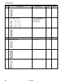
No.
20
Setting items
Front tack pattern
Rectangle
21
Setting range
Radial
Round
Tack
Unit
Default
0: Rectangle
1: Radial
2: Round
3: Tack
4: Taper tack
1
0
0.5 - 5.0 mm
0.1
1.0
0.05 - 1.00 mm
0.05
0.30
– 2.0 - +2.0 mm
0.1
0.0
2
7
1.0 - 5.0 mm
0.1
3.0
– 1.0 - 1.0 mm
0.1
0.0
Taper
tack
Front tack length (except taper tack)
1454Q
22
Front tack pitch (except radial)
1455Q
23
Front tack width correction (except radial)
24
No. of front tack stitch (radial)
1456Q
5 - 11 stitches
1457Q
25
Taper tack length (taper tack)
1458Q
26
Front tack sideways correction (rectangle only)
1459Q
36
HE-8000
5. OPERATION
No.
30
Setting items
Rear tack pattern
Rectangle
31
Setting range
Radial
Round
Unit
Default
0: Rectangle
1: Radial
2: Round
3: Eyelet
1
0
0.5 - 5.0 mm
0.1
1.0
0.05 - 1.00 mm
0.05
0.30
– 2.0 - +2.0 mm
0.1
0.0
2
7
0.1
2.0
Eyelet
Rear tack length (except eyelet)
1460Q
32
Rear tack pitch (except radial, eyelet)
1461Q
33
Rear tack width correction (except radial, eyelet)
1462Q
34
No. of rear tack stitch (radial, eyelet)
5 - 11 stitches
1463Q
35
Eyelet buttonhole radius (eyelet type only)
1.0 - 3.0 mm
1464Q
HE-8000
37
5. OPERATION
No.
Setting items
Setting range
36
Rear tack sideways correction (rectangle only)
Unit
Default
– 1.0 - 1.0 mm
0.1
0.0
1. Triangle
2. Rectangle
3. Saw-shape
1
1
No. of stitches in X direction for saw-shaped rear 2 - 14 stitches
tack vector shape (When sewing saw-shaped
rear tack stitches for rectangular buttonholes)
2
4
1
1
1465Q
37
Rear tack vector shape (rectangle only)
1:
2:
3:
1466Q
38
1467Q
39
No. of stitches in Y direction for saw-shaped rear 1 - 5 stitches
tack vector shape (When sewing saw-shaped
rear tack stitches for rectangular buttonholes)
1468Q
38
HE-8000
5. OPERATION
No.
40
Setting items
Setting range
Start backtack
Unit
Default
0 - 6 stitches
2
2
0.5 - 3.0 mm
0.1
0.5
0.05
0.30
1- 6 stitches
1
4
0: Center knife (standard)
1: Rear knife (feeding)
2: Front knife
3: Front knife + Center knife
However, 2 and 3 are only
valid for two cycles or
more.
1
0
1469Q
41
Start backtack width
1470Q
42
Start backtack pitch
0.10 - 0.80 mm
1471Q
43
End backtack
1472Q
44
Cutter operation
0:
1:
2:
3:
1473Q
HE-8000
39
5. OPERATION
No.
45
Setting items
Setting range
No. of underlays sewn together
Unit
Default
0-1
1
0
0: No saw-shaped underlay
1: Front and rear tack
2: Rear tack only
3: Front tack only
1
0
0-9
1
0
1,000 - 3,000 rpm
0.5 - 6.0 mm
100
0.1
2,000
2.0
0.3 - 1.0 mm
0.1
0.8
2.0 - 10.0 mm
0.1
4.0
1474Q
46
Saw-shaped underlays
1: 2:
3:
1475Q
47
No. of rectangle underlays
1476Q
48
49
Underlay speed
Underlay feed pitch
1477Q
50
Underlay offset
1478Q
51
Underlay sewing start length
1479Q
40
HE-8000
5. OPERATION
No.
52
Setting items
Setting range
Underlay sewing start pitch
0.2 - 2.0 mm
Unit
Default
0.1
1.0
2 - 14 stitches
2
4
1 - 5 stitches
1
1
0: No double stitch
1: Double stitch
2: Crossed double stitch
1
0
1-2
0.0 - 0.8 mm
1
0.1
2
0.3
0.0 - 3.0 mm
0.1
0
1
1
1480Q
53
Saw-shaped underlay bar tack X stitch no.
1481Q
54
Saw-shaped underlay bar tack Y stitch no.
1482Q
55
2-cycle sewing
1: Double stitch 2: Crossed double stitch
1483Q
56
57
No. of bar tacks sewn for 2-cycle sewing
First offset for 2-cycle sewing
1484Q
58
Zigzag underlay stitch width
1485Q
59
Slow start stitches
0 - 4 stitches
60
Slow speed
500 - 1,500 rpm
100
800
61
Rear tack speed
500 - 4,000 rpm
100
4,000
62
Front tack speed
500 - 4,000 rpm
100
4,000
HE-8000
41
5. OPERATION
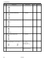
No.
63
Setting items
Setting range
Sewing start tension apply timing
Unit
Default
– 4 - 6 stitches
1
0
– 4 - 4 stitches
1
0
– 4 - 4 stitches
1
0
– 4 - 4 stitches
1
0
– 5 - 0 stitches
1
0
OFF: Condense stitch
0.1 - 1.5 mm
Rear tack width
(Normally set to 1.0)
0.1
OFF
OFF, 1 - 90
(Specify copy source)
1
OFF
1486Q
64
Rear bar tack tension release timing
1487Q
65
Rear bar tack tension apply timing
1488Q
66
Front bar tack tension release timing
1489Q
67
Sewing end tension apply timing
1490Q
68
Rear tack width (rectangle only)
OFF: Condense stitch
0.1 - 1.5 mm
1491Q
69
42
Program copy
HE-8000
5. OPERATION
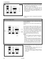
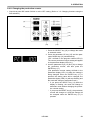
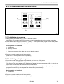
5-4-3. Changing program details
Example 1:
This example shows how to make a
buttonhole (round) setting for program
number 3.
1. Press the SELECT key (13) to change the mode
to automatic, test feed or manual mode. Use the
program No. keys (7) and (8) to select the
program number (example: program number 3),
and then press the ENTER key (17).
(7)
(8)
(13)
(17)
2111Q
(When you press the ENTER key (17), the program
number will be accepted and the program number
LED (6) will stop flashing. The program number will
not be accepted if the ENTER key (17) is not
pressed.)
(6)
(17)
(6)
2112Q
(14)
(13)
2. Press the SELECT key (13) to change the mode
to program mode.
• The parameters for the program number which
was selected in step 1 will appear.
• The parameter number will appear in the
program number LED (6).
• The parameter setting value will appear in the
parameter display LED (14).
2113Q
3. Use the program No. keys (7) and (8) to select
the number for the parameter to be changed.
(Example: Button hole/bar tack setting - Parameter
No. 01)
(7)
(8)
2114Q
HE-8000
43
5. OPERATION
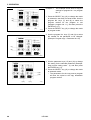
4. Use the parameter keys (15) and (16) to change
the setting for the selected parameter. (Example:
Buttonhole (round) setting value - 3.)
(When you press the ENTER key (17), the
parameter setting will be changed and the
parameter display LED (14) will stop flashing. The
setting will not be changed if the ENTER key (17)
is not pressed.)
(14)
(15)
(16)
(17)
2115Q
5. Repeat steps 3 and 4 to change other parameter
settings.
Checking the length of knife
Use the program No. keys (7) and (8) to select
parameter No. 02.
(Parameter No. 02 is used to set the length of the
knife.)
(14)
(7)
(8)
(15)
(16)
Check that the length of the knife which is has
been installed is the same as the length setting
which appears in the parameter display LED (14).
If the values are different, use the parameter keys
(15) and (16) to change the parameter setting
value so that it is the same as the length of the
knife, and then press the ENTER key (17).
(The length of the knife has now been set.)
NOTE:
Be sure to change the knife length setting if the
knife is replaced with a knife of a different
length.
The stitch length will be automatically determined by the value for the length of the knife which
has been set. Therefore, if the knife length is
not set correctly, problems may occur, such as
the bar tacking stitches being cut by the knife.
(17)
2116Q
6. Press the SELECT key (13) to change the mode
to automatic mode.
* A round buttonhole sewing pattern has now
been set for program No. 03.
* The setting details can be saved in the program notes of the program memos for easy
checking.
(13)
44
2117Q
HE-8000
5. OPERATION
Example 2:
(7)
(8)
(13)
(17)
2118Q
This example shows how to set a
taper tack for the front tack pattern and
an eyelet for the rear tack pattern.
1. Press the SELECT key (13) to change the mode
to automatic, test feed or manual mode. Use the
program No. keys (7) and (8) to select the program
number for the program to use (example: program
No. 10), and then press the ENTER key (17).
2. Press the SELECT key (13) to change the mode
to program mode.
3. Use the program No. keys (7) and (8) to select
the number for the parameter to be changed.
(Example: Button hole/bar tack setting Parameter No. 01).
(7)
(8)
2114Q
4. Use the parameter keys (15) and (16) to change
the setting for the selected parameter (Example:
Buttonhole (free) setting value - 0), and then
press the ENTER key (17).
(15)
(16)
(17)
2119Q
(7)
(8)
(15)
(16)
(17)
2120Q
5. Use the program No. keys (7) and (8) to select
the next parameter number. (Example: Front tack
pattern - Parameter No. 20).
6. Use the parameter keys (15) and (16) to change
the setting for the selected parameter (example:
Taper tack pattern setting value - 4), and then
press the ENTER key (17).
7. Repeat steps 5 and 6 to set parameter No. 30.
(Example: Rear tack pattern - Parameter No. 30)
(Example: Eyelet pattern setting value - 3)
8. Press the SELECT key (13) to change the mode
to automatic mode.
* An eyelet taper-tack buttonhole has now been
set for program No. 10.
* The setting details can be saved in the
program notes of the program memos for easy
checking.
(13)
2121Q
HE-8000
45
5. OPERATION
Example 3:
(7)
(8)
(13)
(17)
2122Q
This example shows how to copy the
settings for program No. 3 to program
No. 11.
1. Press the SELECT key (13) to change the mode
to automatic, test feed or manual mode. Use the
program No. keys (7) and (8) to select the
program number for the program to use
(example: program No. 11), and then press the
ENTER key (17).
2. Press the SELECT key (13) to change the mode
to program mode.
3. Use the program No. keys (7) and (8) to select
the number for the parameter to be changed.
(Example: Program copy - Parameter No. 69).
(7)
(8)
2123Q
4. Use the parameter keys (15) and (16) to change
the setting for the selected parameter (Example:
Copy source setting value - 3), and then press
the ENTER key (17).
5. Press the SELECT key (13) to change the mode
to automatic mode.
* The parameters for the copy source program
will then be copied to the copy destination
program number.
(15)
(16)
(13)
46
(17)
2124Q
HE-8000
5. OPERATION
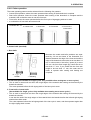
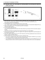
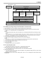
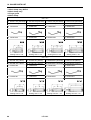
5-4-4. Rear tack vector shape programs
Parameter No. 37
Setting range
1.Triangle
2.Rectangle
3.Saw-shape
1466Q
1. Triangle
• General sewing
2. Rectangle
• This is effective for preventing the material from getting stuck in the needle hole when sewing the rear
tack, which can happen when using lightweight materials.
(An offset is used so that the stitches do not overlap when sewing the reverse zigzagging for the rear
tack.)
* Reducing the number of front tack stitches is effective in preventing the material getting stuck at the
front tack.
* Using a needle plate with a small needle hole (1.2) as well can also help in preventing the material
from getting stuck.
3. Saw-shape
• This is effective for preventing dimples in the rear tack, without the need for underlay sewing.
* The number of stitches for the saw-shape type of sewing is set by means of parameter Nos. 38 and
39.
HE-8000
47
5. OPERATION
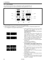
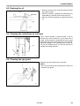
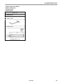
5-4-5. Underlay programs
Four types of underlay patterns are available. These four types can also be combined. Refer to the
examples of use to determine which type of underlay to use.
Parameter No.
45
46
47
58
(5)
(4)
(3)
(1)
2125Q
Underlays sewn together
Saw-shape underlays
(2)
(6)
(8)
(9)
(7)
Rectangle underlays
Zigzag underlay stitch
1. Underlays sewn together
• This type of underlay pattern is used for resewing if the knife has operated before the seam has been
formed, such as when sewing is complete without the upper thread breaking even though the lower
thread has run out. It is particularly useful for sewing up the hole made by the knife beforehand at
times when zigzag stitches do not hold properly.
• The pile of fluffy fabrics is pressed down before sewing, so that the buttonhole finish looks more
attractive.
2. Saw-shape underlay
• This type of underlay is useful for stretch materials to prevent them from stretching.
• It is useful for preventing dimples from forming during bar tacking. Radial-type buttonholes are useful
for preventing dimples.
• It is also useful for strengthening the buttonholes to stop the seam from unravelling, which can often
happen with materials with coarse weaves.
3. Rectangle underlay
• This type of underlay is useful for stretch materials to prevent them from stretching.
• This is effective in preventing seams from unravelling in materials which appear not to have a very
coarse weave. It also serves to reinforce the buttonhole.
• If the seam is hidden and the seam width seems small, you can sew 2 - 3 rectangle underlays to make
the material look more voluminous.
• Underlays such as (1) to (9) in the illustration can be sewn in slightly different positions by changing
the setting value for parameter No. 50 (underlay offset) so that the seam does not become too stiff and
to further increase the feeling of volume.
4. Zigzag underlay stitch
• This is particularly effective in preventing seams from unravelling in materials which appear not to
have a very coarse weave. It also serves to reinforce the buttonhole.
(If parameter No. 58 - Zigzag width [Dimension A in the illustration] is set to about 0.4 mm, the zigzag
underlay stitches will be even stronger than other underlay stitches.)
* If parameter No. 58 is set after saw-shaped underlay stitches or rectangle underlay stitches have been
set, zigzag underlay stitches will only be sewn for the first cycle of underlay stitching.)
NOTE:
When sewing underlays, the number of bar tacking stitches will increase, so that thread breakages or broken
needles may occur. To avoid such problems, reduce the number of underlays or drop the sewing speed.
* When underlays are sewn together, the order of sewing is underlays sewn together → saw-shape
underlays → rectangle underlays.
48
HE-8000
5. OPERATION
5-4-6. Cutter operation
The cutter operating pattern can be selected from the following four patterns.
• Center knife operation, where the cutter operates when sewing of the buttonhole is complete
• Rear knife operation, where the cutter operates when sewing of the buttonhole is complete and the
material is fed so that the cutter is near the front tack
• Front knife, where the cutter operates before the final cycle of zigzagging stitches is sewn
• A combination of front knife and center knife
Parameter No. 44
0: Center knife
1: Rear knife
2: Front knife
3: Front knife +
Center knife
2126Q
0: Center knife (standard)
1: Rear knife
2128Q
2127Q
B
Because the needle and knife positions are separated by 2.2 mm as shown in the illustration, the
distance between the edge of the front tack and the
edge of the buttonhole cannot be set to less than 2.2
mm. In other words, if the knife Y space (A) is set to
0.5 mm, the front tack length (B) cannot be set to
less than 1.7 mm. If you would like the front tack
length to be less than 1.7 mm, the cutter can be
made to operate after sewing and feeding are
complete.
A
2.2 mm
Feeding
2: Front knife (Not available for single cycles. Only available when sewing two or more cycles.)
• This is used in cases such as when the rough edges of the material after cutting are hemmed by the
buttonhole stitches.
The cutter operates before the left zigzag stitch of the last cycle is sewn.
3: Front knife + Center knife
(Not available for single cycles. Only available when sewing two or more cycles.)
• This is used in cases such as when the rough edges of the material after cutting are hemmed by the
buttonhole stitches.
It can also be used if the rough edges of the material block the buttonhole after the left and right zigzag
stitches have been sewn.
The cutter operates before the left zigzag stitch of the last cycle is sewn, and then operates again after
the right zigzag stitch is sewn.
HE-8000
49
5. OPERATION
5-4-7. Cycle program
This example shows how to set C1 to program No. 3 and C2 to program No. 10.
A single cycle program can contain up to nineteen sewing patterns (C1 to C19).
(14)
(6)
(7)
(15)
(16)
(4)
(5)
(13)
(17)
2129Q
1. Press the SELECT key (13) to change the mode to program mode.
2. While pressing the ENTER key (17), press the program no. UP key (7). Repeat this operation twice.
("C1" will appear in the program number LED (6).)
3. Use the parameter keys (15) and (16) to select
the number of the program to be set to C1
(example: program number 3).
(The program number will appear in the parameter
Cutter on
display LED (14).)
The CUTTER ON key (5) can be used to turn
cutter operation on and off. If "." appears in the
display, the cutter is turned on, and if "." does not
Cutter off
appear, the cuter is turned off. However, if the
cutter on indicator (4) is switched off during cycle
sewing, the cutter operation will always be off.
4. Press the ENTER key (17) to accept the program
number for C1.
(The display will stop flashing.)
5. Press the program no. UP key (7).
("C2" will appear in the program number LED (6).
The numbers "3" [the program number for C1]
and "0" will appear in the parameter display LED
(14).)
6. Use the parameter keys (15) and (16) to select
the number of the program to be set to C2
(example: program number 10).
7. Press the ENTER key (17) to accept the program
number for C2.
(The display will stop flashing.)
8. Repeat steps 5, 6 and 7 to enter program numbers
for C3 through to C19.
9. When the SELECT key (13) is pressed, the mode
will change to automatic mode and the program
number "C1" will appear.
50
HE-8000
5. OPERATION
5-4-8. Changing the production counter
• Check that panel DIP switch SW-A4 is at the OFF setting. (Refer to "13. Changing functions using the
DIP switches".)
(3)
(14)
(6)
(15)
(16)
(13)
(17)
2130Q
1. Press the SELECT key (13) to change the mode
to automatic mode.
2. Press the parameter UP key (15) and the parameter DOWN key (16) simultaneously.
("PC" will flash in the program number LED (6).
The current production counter setting will appear
in the parameter display LED (14).)
3. Use the parameter keys (15) and (16) to change
the production counter, and then press the
ENTER key (17).
(The production counter setting will flash in the
parameter display LED (14) while the setting is
being changed. When the ENTER key (17) is
pressed, the setting value will be changed, the
parameter display LED (14) will stop flashing and
the mode will change to automatic mode.)
* If you press the SELECT key (13) while the
display is flashing, the mode will change to
automatic mode without changing the production counter setting.
* If you press the RESET key (3), the production
counter will change to 0, and this change will
be accepted when the ENTER key (17) is
pressed.
HE-8000
51
5. OPERATION
5-4-9. Changing the lower thread counter setting value
• Check that panel DIP switch SW-A4 is at the ON setting. (Refer to "13. Changing functions using the DIP
switches".)
(3)
(14)
(6)
(15)
(16)
(13)
(17)
2130Q
1. Press the SELECT key (13) to change the mode
to automatic mode.
2. Press the parameter UP key (15) and the parameter DOWN key (16) simultaneously.
("bC" will flash in the program number LED (6).
The current lower thread counter setting will
appear in the parameter display LED (14).)
3. Press the RESET key (3).
(The previously-set lower thread counter value
will appear in the parameter display LED (14).)
4. Use the parameter keys (15) and (16) to change
the lower thread counter setting.
5. Press the ENTER key (17).
(The parameter display LED (14) will stop flashing
and the setting value will be changed.)
52
HE-8000
5. OPERATION
5-5. Using the program memos
Insert the program memos (1) into the rear of the
operation box (2) for safekeeping.
(2)
Program memo contents
1. Easy reference guide
2. Error code table
3. Parameter table
4. Program notes
(1)
2131Q
Use a lead pencil to make any additions to the
parameter table and for writing anything into the
program notes. If you do so, additions can be
removed using an eraser and the space can be reused. The program notes are useful for recording
what patterns have been entered into which
programs.
5-6. Adding patterns created using the BAS-PC/300
You can use the BAS-PC/300 to create your own sewing patterns. Up to nine of the patterns which you
create in this way can be programmed into a P-ROM.
DANGER
Wait at least 5 minutes after turning off the power switch and disconnecting the power cord from the
wall outlet before opening the face plate of the control box. Touching areas where high voltages are
present can result in severe injury.
(3)
(2)
2132Q
(1)
2133Q
Adding patterns to a P-ROM
1. Remove the six screws (1), and then open the operator’s side cover (2) of the control box.
NOTE:
When opening the cover (2), hold it securely so that it does not fall down.
2. Remove the P-ROM (3) from the main P.C. board.
3. Create the pattern(s) using the BAS-PC/300. Refer to the Operating Instructions for the BAS-PC/300 for
details on how to create patterns.
4. Add the pattern(s) created using the BAS-PC/300 to the P-ROM (3).
5. Install the P-ROM (3) to the main P.C. board so that it faces as shown in the illustration.
6. Close the cover (2) of the control box, and tighten the six screws (1).
HE-8000
53
5. OPERATION
The program numbers for patterns which have been created using the BAS-PC/300 range from P1 to P9.
However, program numbers which have not yet been assigned to a program will not appear on the program
number LED.
→ 1 → 2 → 3 →….. → 90→
→ P1 → P2 → …… → P9 → 1 → 2 → ……
You can check and change the following parameters for patterns which have been created using the BASPC/300.
No.
54
Setting items
Setting range
00
Sewing speed (zigzag part)
1,000 - 4,000 rpm
02
Length of knife
Value is for checking purposes and
cannot be changed.
08
Knife X position alignment
09
Unit
Default
100
3,600
-
-
-0.5 - 0.5 mm
0.1
0.0
Knife Y position alignment
-0.8 - 0.8 mm
0.1
0.0
16
Running speed (Straight bar tack)
1,000 - 3,000 rpm
100
2,000
48
Underlay speed
1,000 - 3,000 rpm
100
2,000
60
Slow speed
500 - 1,500 rpm
100
800
61
Rear tack speed
500 - 4,000 rpm
100
4,000
62
Front tack speed
500 - 4,000 rpm
100
4,000
HE-8000
6. CHECKING THE SEWING PATTERN
6. CHECKING THE SEWING PATTERN
You can check the sewing pattern which has been programmed, and also the needle zigzagging and feed
operation. Checking can be carried out using test feed mode, or by turning the machine pulley by hand in
manual mode. These two modes can also be combined in order to carry out checking.
6-1. Test feed mode (for checking the sewing pattern without turning the
machine pulley by hand)
(3)
A
(14)
(7)
(15)
(8)
C
(16)
(13)
(17)
2135Q
2134Q
1. Press the SELECT key (13) to change the mode to automatic mode. Use the program No. keys (7) and
(8) to select the number for the program to be checked, and then press the ENTER key (17).
(The program number will stop flashing.)
2. Press the SELECT key (13) to change the mode to test feed mode.
("H***" and the number of stitches in the selected program will appear in the parameter display LED (14).)
3. Depress the treadle from the neutral position [A] to the 2nd step [C].
(The work clamp will drop.)
4. Return the treadle to the neutral position [A], and then depress it once more to the 2nd step [C]. The
needle zigzag and feed mechanisms will each advance by one step while the treadle is being depressed.
In addition, the needle zigzag and feed mechanisms will also advance by one step if you press the
parameter UP key (15).
The needle zigzag and feed mechanisms will also retreat by one step if you press the parameter DOWN
key (16).
(If the knife has been set to operate, the buzzer will sound and "C-On" will appear.)
5. "Ho" will appear in the parameter display LED (14), and the machine will stop at the final stitch position.
6. Return the treadle to the neutral position [A], and then depress it to the 2nd step [C]. The sewing machine
will move to the home position, and the work clamp will rise.
7. Press the SELECT key (13) to change the mode to automatic mode.
• If you press the SELECT key (13) during the checking operation, the mode will change to manual
mode. If you press the SELECT key (13) once more, the mode will change back to test feed mode.
• If you would like to stop checking before the operation has completed, press the RESET key (3). The
sewing machine will move to the home position, and the work clamp will move to the neutral position.
HE-8000
55
6. CHECKING THE SEWING PATTERN
6-2. Manual mode (for checking the sewing pattern by turning the machine
pulley by hand)
(3)
A
(14)
C
(7)
(8)
(13)
(17)
2136Q
2135Q
1. Press the SELECT key (13) to change the mode to automatic mode. Use the program No. keys (7) and
(8) to select the number for the program to be checked, and then press the ENTER key (17).
(The program number will stop flashing.)
2. Press the SELECT key (13) to change the mode to manual mode.
(“H***” and the number of stitches in the selected program will appear in the parameter display LED (14).)
3. Depress the treadle from the neutral position [A] to the 2nd step [C].
(The work clamp will drop.)
4. Turn the machine pulley by hand.
(The needle zigzag and feed mechanisms will each advance by one step each time the machine pulley is
turned.)
(If the knife has been set to operate, the buzzer will sound and "C-On" will appear.)
5. Stop turning the machine pulley when "Ho" appears in the parameter display LED (14) and the pulley is at
the needle up stop position.
6. When the treadle is depressed once more to the 2nd step [C], the sewing machine will move to the home
position, and the work clamp will rise.
7. Press the SELECT key (13) to change the mode to automatic mode.
• If you turn the machine pulley to the needle up stop position and press the SELECT key (13) during
the checking operation, the mode will change to test feed mode.
• If you would like to stop checking before the operation has completed, press the RESET key (3). The
sewing machine will move to the home position, and the work clamp will move to the neutral position.
56
HE-8000
7. CORRECT USE
7. CORRECT USE
CAUTION
Turn off the power switch before installing the needle, otherwise the machine may operate if the
treadle is depressed by mistake, which could result in injury.
7-1. Installing the needle
1. Use a Schmetz Nm 134 needle.
2. Loosen the set screw (1), insert the needle as far
as it will go so that the groove is facing toward
pulley, and then tighten the set screw (1).
* Factory default
Sub class -2, -5
Sub class -3
Schmetz Nm134#90
Schmetz Nm134#75
(1)
2137Q
HE-8000
57
7. CORRECT USE
7-2. Threading the upper thread
CAUTION
Turn off the power switch before threading the thread, otherwise the machine may operate if the
treadle is depressed by mistake, which could result in injury.
Thread the upper thread correctly as shown in the
illustration.
1) When pulling the thread out from the zigzag
thread tension (1), move the tension release lever
(2) in the direction of the arrow to open the
tension discs (3) in order to make it easier to pull
out the thread.
2) After threading the arm thread guide (4), pass the
thread under the thread guide (5) as shown in the
illustration to make it easier to thread.
3) Push the needle bar to the right to make it easier
to pass the thread through the needle.
(5)
(4)
(5)
(6)
(4)
(1)
(2)
(3)
(3)
2138Q
2139Q
For spun thread and
cotton thread
2140Q
NOTE:
The thread tension (6) is used to prevent the upper
thread from becoming knotted, tangled or loose, so
do not touch it. It is tightened only gently. If it is
tightened too firmly, the knob may become damaged.
For polyester thread
Threading the thread at the sewing start position
(3)
(15)
1. Press the RESET key (3).
The work clamp will be lowered.
2. Press the parameter up key (15).
The needle bar will move to the right to make
threading easier.
3. Press the RESET key (3).
The needle bar will move to the center position
and the work clamp will be raised.
2147Q
58
HE-8000
7. CORRECT USE
7-3. Winding the lower thread
CAUTION
Do not touch any of the moving parts or press any objects against the machine while winding the
lower thread, as this may result in personal injury or damage to the machine.
2142Q
(2)
(1)
(2)
1. Place the bobbin all the way onto the shaft.
2. Thread the thread as shown in the illustration,
wind the thread around the bobbin several times,
and then press the bobbin presser (1).
3. Turn on the power switch. Depress the treadle to
set the machine to the home position.
4. While pressing the ENTER key (17) on the
operation panel, depress the treadle until the
machine starts operating, and then release the
key. Only the upper shaft and lower shaft will then
operate; the zigzag and feed mechanisms and
the presser foot will not operate. When the lower
thread has finished winding, return the treadle to
the neutral position.
5. Remove the bobbin, hook the thread onto the
knife (2), and then pull the bobbin in the direction
of the arrow to cut the thread.
(17)
2143Q
2144Q
2145Q
(3)
Adjusting the bobbin winding amount
Loosen the screw (3) and adjust the bobbin presser
(1).
If the thread winds onto the bobbin unevenly
Loosen the set screw (4) and move the bobbin wider
tension bracket (5) up and down to adjust.
* For case A, move the bobbin winder tension
bracket down, and for case B, move it upward.
(1)
(5)
Case A
(4)
Case B
2146Q
2147Q
HE-8000
59
7. CORRECT USE
7-4. Threading the bobbin case
CAUTION
Turn off the power switch before removing or inserting the bobbin case, otherwise the machine
may operate if the treadle is depressed by mistake, which could result in injury.
(2)
(1)
(3)
(5)
(4)
Purl stitch
(seal stitch)
Whip stitch
(plain stitch)
1278Q
1. Insert the bobbin into the bobbin case. Insert as shown in the illustration.
NOTE:
If the bobbin is inserted back to front, the bobbin will spin freely and the work clamp pulse motor will get
out of step.
2. Pass the thread though the slot (1) and then under the tension spring (2) and through the slot (3). When
sewing whip stitches, pull approximately 40 mm of thread out from the thread hole (4), and when sewing
purl stitches, pull approximately 40 mm or thread out from thread hole (5).
3. Insert the bobbin case into the bottom of the rotary hook.
Stitch patterns
Whip stitch (plain stitch)
Front
Back
Purl stitch (seal stitch)
Front
Back
1229Q
1228Q
Whip stitch (plain stitch)
The above stitch pattern in which the upper thread moves over the top and the bottom thread moves over
the bottom of the material in a zigzag pattern is called a “whip” stitch. This pattern is identical to the zigzag
pattern of a lock stitch zigzag machine.
Purl stitch (seal stitch)
The above pattern in which the upper needle thread tension is high and the upper needle follows a straight
line through the seam center while the lower thread moves left to right and intertwines with the upper thread
is called a “purl” stitch.
60
HE-8000
7. CORRECT USE
7-5. Thread tension
The shapes of the seams for all patterns which have been stored in programs 1 to 90 can be set using
parameter No. 11. Make the following adjustments in accordance with the seam shape which has been set.
Lower thread tension
Stronger
Upper thread tension
Zigzag stitch
Weaker
(2)
(1)
Bar tacking stitch
1279Q
1280Q
(3)
2148Q
Whip stitch (plain stitch)
1. Adjust by turning the adjustment screw (1) until the bobbin case drops when it is shaken slightly (0.15 0.25 N) while the thread end coming out of the bobbin case is held.
2. Turn the tack tension control (2) to adjust the thread tension so that a clean whip stitch is obtained at the
bar tacking areas and the zigzag areas. There is no need to loosen the zigzag tension control (3) at this
time. Bar tacking stitches and zigzag stitches are sewn at the tension which is set by the tack tension
control (2), so that zigzag tension is automatically disabled. If the zigzag tension control (3) is loosened,
the upper thread trailing length after upper thread trimming may become longer.
Purl stitch (seal stitch)
1. Adjust by turning the adjustment screw (1) until the bobbin case drops gently by its own weight (0.05 0.15 N) while the thread end coming out of the bobbin case is held.
2. Turn the tack tension control (2) to adjust the thread tension so that a clean whip stitch is obtained at the
bar tacking areas.
3. Turn the zigzag tension control (3) while watching the looping of the zigzag stitch.
HE-8000
61
7. CORRECT USE
Thread take-up spring tension
Turn the thread tension stud (1) to adjust the thread take-up spring tension to between approximately 0.10 0.20 N in accordance with the material to be sewn.
Thread take-up spring height
Loosen the set screw (2), and turn the entire thread tension adjuster to adjust the thread take-up spring
height to between 4 - 6 mm in accordance with the material to be sewn.
Thread take-up spring tension
Thread take-up spring height
4 – 6 mm
Weaker
Stronger
(2)
(1)
2149Q
2150Q
Reference thread tension
Stitch patterns
Upper thread
Lower thread
Upper thread tension
Lower thread tension
Thread take-up spring tension
Thread take-up spring height
Whip stitch
Purl stitch
Polyester #50
Spun #60
Polyester #50
Spun #60
Polyester #50
Spun #60
Polyester #50
Spun #60
0.30 - 0.70 N
0.50 - 0.85 N
0.75 – 2.00 N
1.00 – 2.20 N
0.15 - 0.25 N
0.05 - 0.15 N
0.10 - 0.20 N
4 - 6 mm
2151Q
Upper thread tension for whip stitches
(with zigzag tension open)
When using a program that has whip stitches set,
press the RESET key to lower the work clamp, and
then take the measurement shown in the illustration.
Upper thread tension for purl stitches
(with zigzag tension closed)
When using a program that has purl stitches set,
press the RESET key to lower the work clamp, and
then take the measurement shown in the illustration.
2152Q
62
HE-8000
8. SEWING
8. SEWING
CAUTION
Turn off the power switch at the following times, otherwise the machine may operate if the treadle
is depressed by mistake, which could result in injury.
• When threading the needle
• When replacing the bobbin and needle
• When not using the machine and when leaving the machine unattended.
Do not touch any of the moving parts or press any objects against the machine while sewing, as
this may result in personal injury or damage to the machine.
NOTE:
• The feed arm can move, so be careful of the
clearance.
• When using the machine, check that the oil is
visible through the oil cap. If it cannot be seen,
stop the machine and eliminate the cause of the
problem.
2153Q
8-1. Sewing
2154Q
(7)
(8)
(13)
(17)
C
Fig. 1
A
B
2102Q
1. Turn on the power.
2. Depress the treadle to the 2nd step [C]. [Figure 1]
(Refer to "5-2. Home position return (preparation)".)
3. Press the SELECT key (13) to change the mode
to automatic mode. Use the program No. keys (7)
and (8) to select the number for the program to be
sewn, and then press the ENTER key (17).
4. Set the material in place, and then depress the
treadle from the neutral position [A] to the 1st
step [B]. [Figure 2]
(The work clamp will drop.)
5. Depress the treadle from the 1st step [B] to the
2nd step [C]. [Figure 3]
• The sewing machine will start sewing.
• Once the sewing operation has completed
normally, the production counter will increase
by 1 if in production counter display mode (DIP
switch A-4 = OFF). If in lower thread counter
mode (DIP switch A-4 = ON), the lower thread
counter will decrease by 1.
Fig. 2
2105Q
B
C
Fig. 3
2102Q
HE-8000
63
8. SEWING
8-1-1. If the emergency stop switch is pressed during sewing
The sewing machine will stop and "E-00" will appear in the parameter display LED (14).
Turn the knob of the emergency stop switch to the right to release it.
1. To finish sewing in this condition
Next sewing
1) Press the RESET key (3).
(The feed mechanism will return to the sewing start position and the work clamp will rise.)
2) Sewing will start again when the treadle is depressed.
2. To start sewing again from slightly before or after the emergency stop point
Resuming sewing
1) Press the parameter UP key (15) to move the zigzag and feed mechanisms to the next sewing
position. Press the parameter DOWN key (16) to move the zigzag and feed mechanisms to the
previous sewing position. (The "E-00" display will be cleared at this time.)
2) Move to the position to continue sewing from, and then depress the treadle. The rest of the sewing will
be carried out.
3. To sew from the sewing start point without raising the work clamp (without shifting the material)
Re-sewing
1) While pressing the parameter DOWN key (16), press the RESET key (3).
(The feed mechanism will return to the sewing start position, but the work clamp will not rise.)
2) Depress the treadle to start sewing.
* If panel DIP switch A-3 is set to ON, an emergency stop will occur when the treadle is depressed, in
the same way as when the emergency stop switch is pressed.
NOTE:
Turn the power off before changing the DIP switch settings. If the settings are changed while the power is
still on, they will not take effect.
NOTE:
Forcing emergency stops using the treadle only works while the sewing machine is running. If the sewing
machine is stopped, the work clamp will be raised.
(3)
(14)
(15)
(16)
2155Q
64
HE-8000
8. SEWING
Emergency stop
Thread breakage detection
Press the EMERGENCY STOP switch to stop the machine, and then
reset the switch. (When panel DIP switch A-3 is ON, an emergency
stop occurs when the treadle is depressed backward.)
The machine stops when a
thread breakage is detected.
Thread the thread.
Resuming sewing
Press parameter keys (15)
and (16) to move to the
point to resume sewing.
Re-sewing
(with work clamp still lowered)
While pressing the parameter down
key (16), press the RESET key (3).
Return to the sewing start position
(work clamp lowered).
Next sewing
(work clamp raised)
Press the RESET key (3).
Return to the sewing start
position (work clamp raised).
Depress the treadle. (Machine will start.)
8-1-2. If the thread breaks during sewing
The sewing machine will stop and "E-01" will appear in the parameter display LED (14).
Re-thread the thread.
1. To finish sewing in this condition
Next sewing
1) Press the RESET key (3).
(The feed mechanism will return to the sewing start position and the work clamp will rise.)
2) Sewing will start again when the treadle is depressed.
2. To start sewing again from slightly before or after the thread breakage
Resuming sewing
1) Press the parameter UP key (15) to move the zigzag and feed mechanisms to the next sewing
position. Press the parameter DOWN key (16) to move the zigzag and feed mechanisms to the
previous sewing position. (The "E-01" display will be cleared at this time.)
2) Move to the position to continue sewing from, and then depress the treadle. The rest of the sewing will
be carried out.
3. To sew from the sewing start point without raising the work clamp (without shifting the material)
Re-sewing
1) While pressing the parameter DOWN key (16), press the RESET key (3).
(The feed mechanism will return to the sewing start position, but the work clamp will not rise.)
2) Depress the treadle to start sewing.
If the emergency stop or thread breakage detector operates during sewing, the needle will move to the right
before the sewing machine stops, in order to make threading easier.
HE-8000
65
8. SEWING
8-1-3. Thread breakage before sewing is finished
Set panel DIP switch A-1 to ON.
Even if sewing is complete, leave the work clamp lowered and check the sewing. Then depress the treadle
backward to trim the thread and raise the work clamp.
If the thread breaks just before sewing is complete, and then sewing is completed without the thread
breakage being detected, the following operations are possible.
1. To finish sewing in this condition
Finish
1) Press the RESET key (3).
(The feed mechanism will return to the sewing start position and the work clamp will rise.)
2) Sewing will start again when the treadle is depressed.
2. To continue sewing from around the location of the breakage
Resuming sewing
1) Press the parameter DOWN key (16) to move to position to continue sewing from.
2) If you do not want the cutter to operate, press the CUTTER ON key (5) to turn off the cutter.
3) Depress the treadle. The rest of the sewing will be carried out.
4) After sewing is complete, depress the treadle. The thread will be trimmed and the work clamp will be
raised.
5) Before carrying out any further sewing, press the CUTTER ON key (5) to turn on the cutter.
3. To sew from the sewing start point without raising the work clamp (without shifting the material)
Re-sewing
1) While pressing the parameter DOWN key (16), press the RESET key (3).
(The feed mechanism will return to the sewing start position, but the work clamp will not rise.)
2) If you do not want the cutter to operate, press the CUTTER ON key (5) to turn off the cutter.
3) Depress the treadle to start sewing.
4) After sewing is complete, depress the treadle. The thread will be trimmed and the work clamp will be
raised.
5) Before carrying out any further sewing, press the CUTTER ON key (5) to turn on the cutter and return
the program number to the previous number.
4. To sew from the sewing start point without raising the work clamp in the next program (without
shifting the material)
Re-sewing in the next program
1)The next program number can be retrieved when re-sewing.
(For example, if there is a program which has already been assigned to a different program number
which has the same buttonhole shape and which has underlays sewn together as an added function,
then you can retrieve that program.)
Press the Program No. UP key (7) or the Program No. DOWN key (8) to select the program, and then
press the ENTER key (17).
2) If you do not want the cutter to operate, press the CUTTER ON key (5) to turn off the cutter.
3) Depress the treadle to start sewing.
4) After sewing is complete, depress the treadle.
The thread will be trimmed and the work clamp
(3)
will be raised.
5)
Before
carrying out any further sewing, press the
(14)
CUTTER ON key (5) to turn on the cutter and
(7)
return the program number to the previous
(15)
(8)
number.
(16)
(5)
(13)
(17)
2156Q
66
HE-8000
8. SEWING
* DIP switch A-1 = ON
Sewing completes with
no thread breakage
(work clamp still lowered)
Thread breakage occurs just before sewing is complete, but sewing completes before it is detected
(work clamp still lowered)
Thread the thread.
Resuming sewing
Re-sewing
Re-sewing in the next program
Finishing sewing
Press the parameter down
key (16) to move to the
point to resume sewing.
While pressing the
parameter down key (16)
press the RESET key (3).
(Machine will return to
sewing start position.)
Select a different program to be
retrieved.
* For example, select a program
which includes underlays sewn
together, and then press the
ENTER key (17).
Press the RESET key (3).
(Thread will be trimmed
and work clamp will be
raised.)
Select the cutter operation.
(If cutter operation is not needed, press the CUTTER ON key (5) to turn off the cutter.)
Depress the treadle.
(Resuming sewing)
Depress the treadle.
(Re-sewing)
Depress the treadle backward (Thread will be trimmed and work clamp will be raised.)
Depress the treadle. (Machine will start and next sewing will be carried out.)
* If using a different program, press the CUTTER ON key (5) to turn the cutter back on if it has been turned off.
8-1-4. When resuming sewing in test feed mode or manual mode
1. Use the SELECT key (13) to switch to either test feed mode or manual mode.
2. Move to the point to resume sewing using the operations that apply to whichever mode being used.
* Refer to "6-1. Test feed mode" or "6-2. Manual mode".
NOTE:
If using manual feed mode, raise the needle bar to its highest position before proceeding to step 3.
below.
If the needle bar is not at its highest position when step 3. below is carried out, error "E-02" will be
displayed. Turn the machine pulley to raise the needle bar to its highest position before continuing.
3. While pressing the ENTER key (17), press the SELECT key (13).
* The mode will change to automatic mode and "E-00" will be displayed.
NOTE:
When step 3. is carried out, the mode cannot be returned to test feed mode or manual mode.
4. Press the parameter up key (15) or the parameter down key (16).
* The "E-00" display will be cleared.
5. Depress the treadle.
* Sewing will start from the current position.
8-1-5. Lower thread counter
• When panel DIP switch A-4 is set to ON ... lower thread counter mode
1. When the lower thread counter reaches 0, replace the lower thread.
• The sewing machine will not start at this time, even if the treadle is pressed.
2. Press the ENTER key (17).
• The lower thread counter setting value will appear in the parameter display LED (14) and normal
sewing can then be carried out.
* To change the lower thread counter setting value, refer to "5-4-9. Changing the lower thread counter
setting value".
HE-8000
67
9. MAINTENANCE
9. MAINTENANCE
CAUTION
Turn off the power switch before carrying out cleaning, otherwise the machine may operate if the
treadle is depressed by mistake, which could result in injury.
Be sure to wear protective goggles and gloves when handling the lubricating oil and grease, so
that they do not get into your eyes or onto your skin, otherwise inflammation can result.
Furthermore, do not drink the oil or eat the grease under any circumstances, as they can cause
vomiting and diarrhoea. Keep the oil out of the reach of children.
9-1. Cleaning
(1)
2157Q
2158Q
Remove lint and dust from the thread passages (1).
Remove lint and dust from around the work clamp.
Remove the bobbin case, and remove lint and dust
from around the shuttle.
Clean away any thread scraps and cotton dust from
around the lower thread trimmer mechanism.
2159Q
68
HE-8000
9. MAINTENANCE
9-2. Draining the oil
1. Remove the belt cover, and then gently tilt back
the machine head.
2. Place the oil tank (1) against the underside of the
work table (2), and then remove the screw (3).
3. After the oil has all drained out, tighten the screw
(3).
(3)
Bed base
(2)
(1)
2160Q
9-3. Cleaning the control box air inlet port
Use a vacuum cleaner to clean the filter in the air
inlet port (2) of the control box (1) at least once a
month. If the machine is used while the air inlet port
is blocked, the inside of the control box will overheat.
When this happens, the overheating error code (“E40”) will be displayed and you will not be able to
operate the sewing machine.
(1)
(2)
2161Q
9-4. Cleaning the eye guard
Wipe the eye guard clean with a soft cloth.
NOTE:
Do not use solvents such as kerosene or thinner to
clean the eye guard.
2162Q
HE-8000
69
9. MAINTENANCE
9-5. Checking the needle
Always check that the tip of the needle is not broken
before starting sewing.
2163Q
9-6. Cleaning the length feed plate
Clean the length feed plate (1) if foreign materials
such as shavings start getting onto the material.
1. Loosen the screw (2), and then remove the length
feed plate (1).
2. Clean the underside of the length feed plate (1)
and the needle plate (3).
(2)
(1)
(3)
2164Q
70
HE-8000
10.STANDARD ADJUSTMENTS
10. STANDARD ADJUSTMENTS
CAUTION
Maintenance and inspection of the sewing
machine should only be carried out by a
qualified technician.
Use both hands to hold the machine head
when tilting it back or returning it to its
original position. If only one hand is used,
the weight of the machine head may cause
your hand to slip, and your hand may get
caught.
Ask your Brother dealer or a qualified electrician to carry out any maintenance and
inspection of the electrical system.
If the power switch needs to be left on when
carrying out some adjustment, be extremely
careful to observe all safety precautions.
Turn off the power switch and disconnect
the power cord from the wall outlet at the
following times, otherwise the machine may
operate if the treadle is depressed by
mistake, which could result in injury.
・When carrying out inspection, adjustment
and maintenance
・When replacing consumable parts such
as the rotary hook
If any safety devices have been removed,
be absolutely sure to re-install them to their
original positions and check that they
operate correctly before using the machine.
NOTE:
• The pulse motor may become warm. Be careful not to touch it when tilting back the machine head.
• The feed pulse motor cooling fan spins while the machine power supply is turned on. Be careful of this
when tilting back the machine head.
• Take care when handling the knife.
Turn off the power supply before carrying out all but the following tasks.
“10-1. Needle bar height”
“10-2. Needle and hook timing adjustment”
“10-3. Adjusting the clearance between needle and hook point”
“10-7-2. Adjusting the upper thread scissors opening timing”
“10-9. Adjusting the bobbin presser”
Turn on the power, and after the sewing machine returns to the home position, press the RESET key before
carrying out the above adjustments.
* The work clamp will drop and "AdJ" will appear in the numeric display. The sewing machine will not
operate when the treadle is pressed at this time.
10-1. Needle bar height
(2)(3)
(4)
(5)
(1)
2165Q
After the sewing machine has returned to the home
position, press the RESET key before carrying out
this adjustment.
1. Set the needle bar (1) to its lowest position.
2. Remove the rubber cap (2) from the face plate, and
then loosen the screw (3) of the needle bar clamp.
3. Insert the “1” part of the gauge (4) between the
needle plate (5) and the lower edge of the needle
bar (1), and touch the needle bar against the
gauge.
4. Tighten the screw (3).
5. Install the rubber cap (2).
* Different gauges are used for each of the three
sub-classes -2, -3 and -5, so make sure that the
gauge being used matches the specifications and
application for the sewing machine being adjusted.
HE-8000
71
10. STANDARD ADJUSTMENTS
10-2. Needle and hook timing adjustment
1267Q
(3)
(4)
(6)
(5)
Lowest
position
Mark
(1)
(2)
2166Q
2168Q
1306Q
After the sewing machine has returned to the home position, press the RESET key before carrying out this
adjustment.
1. Loosen the two screws (2) of the rotary hook joint (1).
2. Turn the pulley in the regular direction of rotation (toward the front) so that the needle bar (3) just begins
to rise from its lowest position.
3. Insert the “2” part of the gauge (4) between the needle plate (5) and the lower edge of the needle bar (3),
and then align the rotary hook point (6) with the center of the needle when the needle bar contacts the
gauge. Different gauges are used for each of the three sub-classes -2, -3 and -5, so check the timing
gauge identification marks before using them.
NOTE:
When installing the rotary hook joint, install using the set screw so that the oil inlets in the rotary hook and
rotary hook joint (7) are aligned.
(7)
2169Q
10-3. Adjusting the clearance between needle and hook point
0.01 - 0.08 mm
(2)
(3)
(1)
(4)
1308Q
2170Q
After the sewing machine has returned to the home position, press the RESET key before carrying out this
adjustment.
Loosen the screws (3) and move the rotary hook (4) forward or back until there is a clearance of 0.01 to 0.08 mm
between the needle (1) and the hook point (2).
72
HE-8000
10.STANDARD ADJUSTMENTS
10-4. Adjusting the inner rotary hook and rotary hook holder overlap
(1)
(3)
Loosen the screw (3) to adjust so that the tip of the
rotary hook holder (1) does not protrude past the
edge A of the inner rotary hook (2).
A
(2)
2171Q
10-5. Adjusting the work clamp pressure
1. The standard distance A is 30 mm (approximately
30 N).
2. Loosen the nut (1) and turn the presser adjusting
screw (2) to adjust the work clamp pressure.
(2)
(1)
A
2172Q
10-6. Adjusting the knife installation
2173Q
(2)
(1)
Lowest
position
Top of needle plate
(3)
1.5 – 2.0 mm
Lowest
position
Top of needle
plate
2174Q
(4)
1. Install the knife with the screw (2) so that the top
(1) of the knife blade is aligned with the top of the
needle plate when the knife is pressed down by
hand to its lowest position.
For the flat cutter (3), install with the screw (2) so
that the top (1) of the knife blade is 1.5 – 2.0 mm
above the top of the needle plate.
NOTE:
When the knife is driven by the solenoid, the
movement will be approximately 2 mm greater
than that shown in the illustration.
NOTE:
If the knife does not cut properly, the knife may get
stuck in the material and not return. If this happens,
replace or sharpen the knife.
A special needle plate which helps to prevent the
knife from getting stuck and which helps maintain
the cutting edge is available as an option.
2. Loosen the screw (5) to adjust so that the
clearance between the cutter and the needle bar
(4) is 0.3 mm.
* Check that the needle bar (4) does not touch
the cutter when it moves sideways.
(5)
0.3 mm
2175Q
HE-8000
73
10. STANDARD ADJUSTMENTS
10-7. Adjusting the upper thread trimming
The standard distance (A) between the upper thread scissors (1) and the center of the needle is 5.5 to 6.0 mm
when the work clamp is lowered by pressing the RESET key after setting the machine to the home position.
(1)
(A) 5.5 – 6.0 mm
Center of the needle
2176Q
10-7-1. Adjusting the installation height of the upper thread scissors
2177Q
2178Q
1 mm
(2)
(1)
(3)
1 mm
Loosen the screw (2), and then move the upper
thread scissors (1) up or down to adjust the
clearance between the upper thread scissors (1) and
the work clamp (3) to approximately 1 mm.
NOTE:
The work clamp (3) will tilt when sewing joints, so
adjust so that the upper thread scissors (1) do not
touch it. If the upper thread scissors (1) touch the
work clamp (3), the work clamp lifter pulse motor
may get out of step.
* If the tilting of the work clamp (3) causes skipped
stitches to occur when sewing material joints,
use the accessory auxiliary sheet (4) as shown in
the illustration.
(4)
(4)
2179Q
74
HE-8000
10.STANDARD ADJUSTMENTS
10-7-2. Adjusting the upper thread scissors opening timing
After the sewing machine has returned to the home position, press the RESET key before carrying out this
adjustment.
2180Q
2182Q
Start touching at 1.5 – 2.5 mm
(C)
(2) (D)
(B)
(1)
(b)
0.5 mm
0.5 mm
(b)
(B)
(3)
0.5 mm
(c)
Approx. 2 mm
(5)
(4)
(8)
(9)
(7)
(1)
(6) Approx.
1.0 – 1.5 mm
(4)
(2)
0.5 mm
(c)
(C)
2181Q
2183Q
<Gradual opening timing adjustment>
1. Loosen the screws (1), and then adjust so that the distance (b) between ridge line (B) on the opening
cam (2) and the upper thread scissors (3) is 0.5 mm, and so that ridge line (B) on the opening cam is
parallel to the feed direction.
2. Loosen the screw (4), and then adjust so that the distance (c) between the rising section (C) of the upper
thread scissors (3) and the tip of the opening cam (2) is approximately 0.5 mm when the upper thread
scissors (3) are closed.
If you would like the scissors to start opening earlier, make the distance smaller. However, if the distance
is too small, check that the work clamp does not touch the rising section (C) of the upper thread scissors
(3) of the opening cam (2) when it is lowered and prevent the upper scissors (3) from opening.
* Apply grease to the inclined face (D) of the opening cam (2).
<Scissors fully opening timing adjustment>
1. Loosen the screw (5), and then adjust the support plate (8) so that the back plate (6) and the cam (7)
overlap by approximately 1.0 – 1.5 mm.
* If the amount of overlap is too small, the upper thread scissors will not open properly and the upper
thread scissors and the cutter may touch each other.
2. Loosen the screw (9), and then adjust the clearance between the bend in the back plate (6) and the cam
(7) to approximately 2 mm. If you would like the scissors to start opening earlier, make this clearance smaller.
3. Check that the upper thread scissors (3) open smoothly during feeding.
NOTE:
If the upper thread scissors (3) do not open smoothly, the upper thread scissors (3) may touch the cutter
and needle breakage may occur.
HE-8000
75
10. STANDARD ADJUSTMENTS
10-8. Adjusting the lower thread clamp timing
Loosen the set screw (2) of the feed arm support (1),
and then align the reference line A on feed guide
shaft B (3) with the edge of the feed arm support (1).
When the feed mechanism moves by approximately
6 - 7 mm, the opening plate (4) will move and the
lower thread retainer (5) will open. Move feed guide
shaft B (3) to the left or right to change the opening
timing.
(5)
(2)
(3)
A
(4)
(1)
2184Q
10-9. Adjusting the bobbin presser
After the machine head has returned to the home
position, press the RESET key before carrying out
this adjustment.
1. Loosen the set screw (1), and then adjust so that
the bobbin presser (2) goes into the hole in the
bobbin case (3).
2. Check that the work clamp is at the home position,
and then loosen the nut (4) and turn the screw (5)
to adjust the clearance A between the bobbin
presser (2) and the edge of the bed to approximately 12.5 mm.
(2)
A
(3)
(4)
(1)
(5)
2185Q
10-10. Adjusting the needle up stop position
The needle up stop position is adjusted so that the
index mark (2) on the machine pulley (1) is inside the
mark (4) on the belt cover (3).
If adjustment is necessary, loosen the screw (5) of
the machine pulley (1) and adjust the position of the
machine pulley (1). The machine pulley (1) stops
later if it is turned clockwise, and it stops later if it is
turned counter clockwise.
The screw (6) is a screw for detecting the machine
stop position, and should not be loosened.
NOTE:
If the index mark (2) is not inside the mark (4)
when the sewing machine is started, error code
“E-02” will be displayed. Turn the machine pulley
to move the index mark (2) to the correct position
and then start the sewing machine.
(6)
(3)
(4)
(1)
(2)
(5)
2186Q
76
HE-8000
11.CHANGING FUNCTIONS USING THE MEMORY SWITCHES
11. CHANGING FUNCTIONS USING THE MEMORY
SWITCHES
• Refer to the memory switch table for details of memory switch settings.
• The memory switches are valid for all programs (program Nos. 1 to 90).
• When a memory switch number is being displayed in the program number LED (6), a dot will appear after
the memory switch number. (Example: 00.)
(14)
(6)
(7)
(15)
(8)
(16)
(13)
(17)
2187Q
1. Press the SELECT key (13) to change the mode
to program mode.
2. While pressing the ENTER key (17), press the
program no. UP key (7).
• The memory switch number "00." will appear
in the program number LED (6). The setting
for that memory switch number will appear in
the parameter display LED (14).
3. Use the program No. keys (7) and (8) to select
the number for the memory switch to be changed.
• The setting for that memory switch number will
appear in the parameter display LED (14).
4. Use the parameter keys (15) and (16) to change
the memory switch setting.
• The memory switch setting will flash while it is
being changed.
5. Press the ENTER key (17) to accept the new
setting.
• The memory switch setting will stop flashing.
• Press the SELECT key (13) to change the
mode to automatic mode.
HE-8000
77
11. CHANGING FUNCTIONS USING THE MEMORY SWITCHES
Memory switch table
Effective for all programs
No.
00.
Setting items
Cutter power
Setting range
Weak
-1
0
1
2
3
4
Light
Light - Normal
Normal
Normal - Medium
Medium
Heavy
Unit
1
Default
1
1
1
1
0
0
13
1
0.1
1
10
OFF
0
1
0
1
100
1
1
-
0
OFF
1
0
OFF
-
OFF
Strong
02.
03.
04.
05.
06.
07.
08.
09.
10.
11.
12.
13.
14.
Work clamp lifting speed
Work clamp lowering speed
Work clamp height when treadle is
depressed backward
Work clamp height at neutral position
Soft press height
Threadhold valve correction when
work clamp is lifted
Threadhold valve correction when
work clamp is lowered
Threadhold valve correction at start
Extension time for continuous sewing
Home position return cycle
Feed timing
Cutter dimension display during automatic mode
–4-4
–4-4
1 - 13 mm
1 - 13 mm
OFF, 0.1 - 8.0 mm
–10 - 10
–10 - 10
–10 - 10
OFF, 100 - 1,000 ms
OFF, 1 - 10
–10 - 10 (× 0.24°)
ON: Cutter dimensions are
displayed.
OFF: Production counter or
bobbin thread counter is
displayed.
Program number changing enabled ON: Program numbers can be
when program lock is set
changed
and
the
programmer
can
be
started.
OFF: Program numbers cannot
be changed and the
programmer cannot be
started.
Memory switch No. 07., 08., 09.
Neutral position
Work clamp lowered ON position
No. 08.
Machine start ON position
No. 09.
Work clamp raised
ON position
No. 07.
2188Q
78
HE-8000
12. PROGRAM INITIALIZATION
12. PROGRAM INITIALIZATION
(3)
(6)
(14)
(5)
2189Q
12-1. Initializing all programs
1. While pressing the RESET key (3), turn on the power switch.
All LEDs on the operation panel will illuminate and the buzzer will sound continuously for 8 seconds.
2. Once all programs have been initialized, [- -] and [- - - -] will appear in the program number LED (6) and
the parameter display LED (14) respectively.
Settings which are initialized
1. Parameters
2. Memory switches
3. Production counter and lower thread counter
* If any cycle programs have been set, they will also be erased.
3. Return the sewing machine to the home position
(Refer to “5-2. Home position return (preparation)”.)
12-2. Initializing a single program
1. Select the number of the program to be initialized, and then turn off the power.
2. While pressing the CUTTER ON key (5), turn on the power switch.
The number of the program that will be initialized will appear in the program number LED (6), and then all
other LEDs will illuminate and the buzzer will sound four times.
3. When all parameters of the selected program have been initialized, and [- -] and [- - - -] will appear in the
program number LED (6) and the parameter display LED (14) respectively.
Settings which are initialized
1. Parameters
4. Return the sewing machine to the home position.
(Refer to “5-2. Home position return (preparation)”.)
HE-8000
79
13. CHANGING FUNCTIONS USING THE DIP SWITCHES
13. CHANGING FUNCTIONS USING THE DIP
SWITCHES
13-1. Panel DIP switches
A
B
2190Q
1. Slide the panel side cover to open it.
2. Change the DIP switch setting.
* Refer to the DIP switch table for an explanation of the functions of each DIP switch.
3. Slide the panel side cover downward to close it.
NOTE:
Turn the power off before changing the DIP switch settings.
If the settings are changed while the power is still on, they will not take effect.
80
HE-8000
13. CHANGING FUNCTIONS USING THE DIP SWITCHES
Panel DIP switch table
DIPSWA
No.
1
2
3
4
5
6
7
8
ON
OFF
ON
OFF
ON
OFF
ON
OFF
ON
OFF
ON
OFF
ON
OFF
ON
OFF
Setting item
Work clamp remains lowered after sewing is complete (lifts when pedal is
depressed)
Work clamp lifts after sewing is complete
–
–
Emergency stop using work clamp lifter switch enabled during automatic sewing
Emergency stop using work clamp lifter switch disabled during automatic sewing
Display setting during automatic mode = lower thread counter (Default: 100)
Display setting during automatic mode = production counter (Default: 0)
2-cycle sewing ON
(All programs will be set to 2-cycle sewing regardless of the setting for
parameter No. 55.)
2-cycle sewing OFF
–
–
Upper thread breakage detection disabled
Upper thread breakage detection enabled
Programs disabled
Programs enabled
Default
OFF
OFF
OFF
OFF
OFF
OFF
OFF
OFF
DIPSWB
No.
ON
1
OFF
ON
2
OFF
ON, ON, ON
ON, ON, OFF
ON, OFF, ON
ON, OFF, OFF
3, 4, 5
OFF, ON, ON
OFF, ON, OFF
OFF, OFF, ON
OFF, OFF, OFF
ON
6
OFF
ON, ON
ON, OFF
7, 8
OFF, ON
OFF, OFF
Setting item
–
–
–
–
Work clamp size: 7.3 × 75 mm (Sewing area: 6.0 × 70 mm)
Work clamp size: 7.3 × 36 mm (Sewing area: 6.0 × 32 mm)
Work clamp size: 7.3 × 24.5 mm (Sewing area: 6.0 × 20 mm)
Work clamp size: 6.8 × 36 mm (Sewing area: 5.4 × 32 mm)
Work clamp size: 6.8 × 24.5 mm (Sewing area: 5.4 × 20 mm)
Panel DIP switches B-7 and B-8 are enabled.
Work clamp size: 5.4 × 19 mm (Sewing area: 4.0 × 15 mm)
Panel DIP switches B-7 and B-8 are enabled.
Needle plate size: 5.4 mm (Max. needle zigzag feed width = 4.0 mm)
Needle plate size: 7.3 mm (Max. needle zigzag feed width = 6.0 mm)
Work clamp size: 7.3 × 47 mm (Sewing area: 6.0 × 40 mm)
Work clamp size: 6.8 × 47 mm (Sewing area: 5.4 × 40 mm)
Work clamp size: 5.4 × 24.5 mm (Sewing area: 4.0 × 20 mm)
Work clamp size: 5.4 × 36 mm (Sewing area: 4.0 × 32 mm)
Default
OFF
OFF
OFF, OFF, OFF
OFF
OFF, OFF
* If the programs are initialized when Nos. 3, 4 and 5 are set to OFF, OFF and ON (Work clamp size: 5.4 ×
19 mm [Sewing area: 4.0 × 15 mm]) respectively, the initial value for parameter No. 02 - Cutter size will
be set to 6.0.
HE-8000
81
13. CHANGING FUNCTIONS USING THE DIP SWITCHES
13-2. Control circuit board DIP switches
DANGER
Wait at least 5 minutes after turning off the power switch and disconnecting the power cord from
the wall outlet before opening the face plate of the control box. Touching areas where high voltages
are present can result in severe injury.
1. Remove the six screws (1), and then open the
operator's side cover (2) of the control box.
NOTE:
When opening the cover (2), hold it securely so
that it does not fall down.
2. Change the setting of the DIP switch (3).
• Refer to the DIP switch table for an explanation of the functions of each DIP switch.
3. Close the cover (2) of the control box, and tighten
the six screws (1).
NOTE:
Turn the power off before changing the DIP switch
settings.
If the settings are changed while the power is still
on, they will not take effect.
(3)
(2)
(1)
2191Q
82
HE-8000
13. CHANGING FUNCTIONS USING THE DIP SWITCHES
DIP switch inside the control box table
DIPSW1
1
2
3
4
5
6
7
No.
ON
OFF
ON
OFF
ON
OFF
ON
OFF
ON
OFF
ON
OFF
ON
OFF
ON
8
OFF
Setting item
–
–
–
–
–
–
–
–
–
–
–
–
Three warning beeps
Continuous warning beep
Needle feed motor excitation turned off during emergency stop and thread
breakage
Needle feed motor excitation not turned off during emergency stop and
thread breakage
Default
OFF
OFF
OFF
OFF
OFF
OFF
OFF
OFF
DIPSW2
1
2
3
4
5
6
7
8
No.
ON
OFF
ON
OFF
ON
OFF
ON
OFF
ON
OFF
ON
OFF
ON
OFF
ON
OFF
Setting item
Pedal: for standing operation
Pedal: for seated operation
Starting possible only when work clamp is lowered
Starting possible regardless of work clamp position
–
–
–
–
–
–
100V, 110V specifications
200V, 400V specifications
–
–
–
–
HE-8000
Default
OFF
OFF
OFF
OFF
OFF
OFF/ON
OFF
OFF
83
14. GAUGE PARTS LIST
14. GAUGE PARTS LIST
Needle plate
<For "-2">
S50663-001 (1.2mmS)
S50664-001 (1.4mmS)
S50665-001 (1.6mmS)
<For "-3">
S51248-101 (1.2mmS)
S51249-101 (1.4mmS)
<For "-5">
S55344-001 (1.2mm)
84
S54522-001 (1.4mm)
HE-8000
S51250-101 (1.6mmS)
14. GAUGE PARTS LIST
For "flat cutter"
<For "-2">
Needle plate
S50321-001 (1.2mmS)
Plastic plate
151843-001
<For "-3">
Needle plate
S50322-101 (1.2mmS)
Plastic plate
156612-001
HE-8000
85
14. GAUGE PARTS LIST
*1
*2
*3
*4
Work clamp assy, W/F-G
Work clamp assy
Finger guard
Work clamp
<For "-2">
*1 S37101-102 (16mmRS) *1 S37100-102 (25mmRS) *1 S55347-002 (25mmRSW) *1 S37109-102 (32mmRS)
*2 159764-202 (16mmRS) *2 159765-202 (25mmRS) *2 S55346-002 (25mmRSW) *2 159766-202 (32mmRS)
*3 159079-000
*3 159080-000
*3 159080-000
*3 159081-000
*4 159761-002
*4 159762-002
*4 S55345-002
*4 159763-002
Sewing area 4 × 20
Sewing area 4 × 32
Sewing area 6 × 32
Sewing area 6 × 40
<For "-3">
*1 S37103-101 (16mm)
*1 S37102-101 (25mm)
*1 S55350-001 (25mmW) *1 S37110-101 (32mm)
*2 S01466-201 (16mm)
*2 S01467-201 (25mm)
*2 S55349-001 (25mmW) *2 S01468-201 (32mm)
*3 159079-000
*3 159080-000
*3 159080-000
*3 159081-000
*4 145136-001
*4 144630-001
*4 S55348-001
*4 144632-001
Sewing area 4 × 20
86
Sewing area 4 × 32
Sewing area 5.4 × 32
HE-8000
Sewing area 5.4 × 40
14. GAUGE PARTS LIST
*1
*2
*3
*4
Work clamp assy, W/F-G
Work clamp assy
Finger guard
Work clamp
<For "-5">
*1 S54518-101
*2 S54514-101
*3 S54517-000
*4 S54515-001
Sewing area 6 × 70
HE-8000
87
14. GAUGE PARTS LIST
Cutter
S51117-001
S51290-001
1/4
S51355-001
3/8
S51356-001
11/16
3/4
S51359-001
S51351-001
S51352-001
7/16
S25642-001
1/2
S51357-001
13/16
7/8
S51360-001
29
S01273-001
1/2
88
S03280-001
9/16
S01275-001
5/8
HE-8000
9/16
3/4
S51354-001
5/8
S51358-001
1
S01271-001
32
S01274-001
S51353-001
3/8
S01276-001
7/8
S01272-001
7/16
S35630-001
1
15. ERROR CODE TABLE
15. ERROR CODE TABLE
DANGER
Wait at least 5 minutes after turning off the power switch and disconnecting the power cord from
the wall outlet before opening the face plate of the control box. Touching areas where high voltages
are present can result in severe injury.
If a malfunction should occur with the sewing machine, a buzzer will sound and an error code will appear in
the display window.
Follow the remedy procedure to eliminate the cause of the problem.
For errors which do not require the power to be turned off (i.e. errors which can be reset), two short beeps
will sound. For error E-02, three short beeps will sound.
For errors which require the power to be turned off (i.e. errors which cannot be reset), a single long beep will
sound.
Code
Cause
Remedy
To restart sewing: Press the parameter down key and
then depress the treadle to step 2.
To cancel sewing: Press the RESET key.
To restart sewing: Press the parameter down key and
then depress the treadle to step 2.
To cancel sewing: Press the RESET key.
E-00
EMERGENCY STOP switch was pressed.
E-01
Upper thread breakage
E-02
Needle up sensor is OFF.
Turn the machine pulley by hand to raise the needle.
E-05
Zigzag positioning is not carried out.
Turn off the power.
E-06
Feed positioning is not carried out.
Turn off the power.
E-07
Work clamp positioning is not carried out.
Turn off the power.
E-08
Cutter home position sensor is off.
Turn off the power.
E-20
Feed and work clamp motor overcurrent
Turn off the power.
E-21
Zigzag motor overcurrent
Turn off the power.
E-30
Treadle is depressed to step 2.
Return the treadle to the neutral position.
E-31
Treadle is depressed to step 1.
Return the treadle to the neutral position.
E-32
Treadle is depressed backward.
Return the treadle to the neutral position.
E-40
Control board heat sink is overheating.
Turn off the power.
E-41
Inside air circulation fan problem
Turn off the power.
E-42
Exhaust fan problem
Turn off the power.
E-44
2-step power supply circuit board +55V relay error
Turn off the power.
E-50
Pattern shape does not match pattern shape specifications.
Pattern shape for data created using the BAS-PC/300
does not match the pattern shape specifications.
Turn off the power.
E-51
X pitch error
Turn off the power.
E-52
Y pitch error
Turn off the power.
E-54
Overall cycle program stitch no. error
Exceeds 3,000 stitches.
Clear the cycle program and reset automatically.
E-55
Stitch no. error
Exceeds 700 stitches. Turn off the power.
E-59
Sewing data error
Turn off the power.
Re-initialize the programs.
HE-8000
89
15. ERROR CODE TABLE
Code
Cause
Remedy
E-62
Needle up error during operation
Turn off the power.
E-63
Needle down error during operation
Turn off the power.
E-64
Timing signal error during operation
Turn off the power.
E-70
Machine motor running error
Turn off the power.
E-74
EEPROM error
Turn off the power.
E-80
Communication ready error
Turn off the power.
E-81
Communication error
Turn off the power.
E-90
Machine motor overload
Excessive load during sewing. Turn off the power.
E-92
Machine motor operation error
Turn off the power.
E-93
Blown solenoid fuse
Turn off the power. Replace the fuse.
E-94
Machine motor IC error
Turn off the power.
E-95
Power supply voltage error (high)
Power supply voltage is too high. Turn off the power.
E-96
Power supply voltage error (low)
Power supply voltage is too low. Turn off the power.
ArEA
Sewing data values exceed the needle plate size or
work clamp size which have been set using the panel
DIP switches.
Three resetting methods are available depending on
the application.
A. By selecting a different program number (If you would
like to keep the program which exceeds the area.)
Press the SELECT key.
Select a different program number.
Press the ENTER key.
If the data for the selected program number does not
exceed the sewing area, the error will be cleared.
B. By initializing the program
While pressing the ENTER key, press the RESET key.
* All parameters (00 to 69) for the program will
then be initialized and the machine will switch to
program mode.
C. By initializing all programs
Refer to "12. PROGRAM INITIALIZATION".
C-Er
When using the multi-working knife, the knife operation
distance cannot be reduced.
Three resetting methods are available depending on the
application.
A. Replace the knife with a longer knife.
Press the SELECT key to change to automatic mode.
Press the SELECT key to change to program mode.
Enter the length of the new knife as the setting for
parameter 02 (Length of knife).
Press the SELECT key to change to automatic mode.
* If "C-Er" is displayed again, replace with an even
longer knife.
B. By initializing the program
Initialize only the programs which cause "C-Er" to be
displayed.
While pressing the ENTER key, press the RESET key.
* All parameters (00 to 69) for the program will be
initialized.
C. Change the zigzag pitch and zigzag stitch length
(multi-working knife).
1. Press the SELECT key to change to automatic mode.
Press the SELECT key to change to program mode.
2. Reduce the setting value for parameter 04 (Zigzag
pitch). Increase the setting for parameter 03 (Zigzag
stitch [multi-working knife]).
3. Press the SELECT key to change to automatic mode.
* If "C-Er" is still displayed, repeat steps 1. to 3.
90
HE-8000
16. TROUBLESHOOTING
16. TROUBLESHOOTING
Problem
Upper thread breaks
Cause
Poor thread
tightening
Remedy
Page
Burrs in needle hole.
Needle
Replace the needle.
57
Needle is
incorrectly installed.
Needle position
Install the needle
correctly.
57
Threading is
incorrect.
Threading
Thread the upper
thread correctly.
58
Upper thread tension
is too strong.
Main and auxiliary
tension
Adjust to an
appropriate tension.
61
Thread is too thick
for the needle hole.
Needle and thread
Replace the needle with
one that is suitable for
the thread.
Lower thread tension
is too strong.
Lower thread tension
Adjust to an
appropriate tension.
61
Bobbin case
threading is incorrect.
Bobbin case
threading
Thread the bobbin
correctly to match the
sewing.
60
Needle is incorrectly
installed.
Needle position
Install the needle
correctly.
57
Threading is
incorrect.
Threading
Thread the upper
thread correctly.
58
Needle and rotary hook
timing is incorrect.
Needle and rotary
hook timing
Adjust the timing of the
needle and rotary hook.
72
Clearance between
Needle and rotary hook
is too large.
Needle and rotary
hook clearance
Adjust the clearance
between the needle and
rotary hook.
72
Needle bar height is
incorrect.
Needle bar height
Adjust the height of
the needle bar.
71
Lower thread tension
is too strong.
Lower thread tension
Adjust to an
appropriate tension.
61
Thread in bar tacking
area is not tight.
Tension at tack
tension
Adjust the tack
tension.
61
Thread in zigzag sewing
area is not tight.
Tension at zigzag
tension
Adjust the zigzag
tension.
61
Clearance between inner
rotary hook and rotary hook
holder is incorrect.
Clearance between inner
rotary hook and rotary hook
holder
Adjust the clearance between the inner rotary hook
and rotary hook holder.
73
Lower thread breaks
Skipped stitches
Check
HE-8000
91
16. TROUBLESHOOTING
Problem
Needle breaks
Presser foot pulse
motor is out of step.
Upper shaft cannot
be turned manually.
Sewing machine does not
start after emergency stop.
Cutter blade damaged.
92
Cause
Check
Remedy
Page
Needle is incorrectly
installed.
Needle position
Install the needle
correctly.
57
Needle and rotary hook
timing is incorrect.
Needle and rotary
hook timing
Adjust the timing of the
needle and rotary hook.
72
Buttonhole width or
length is incorrect.
Work clamp
Replace the work
clamp.
Upper thread scissors
do not open smoothly.
Upper thread
scissors opening
Adjust the upper thread
scissors opening timing.
Upper thread scissors
position is incorrect.
Upper thread
scissors position
Adjust the position of the
upper thread scissors.
Upper thread scissors
installation is incorrect.
Clearance between upper
thread scissors and work
clamp
Install the upper thread
scissors correctly.
74
Bobbin is spinning
loosely.
Bobbin insertion
method
Insert the bobbin
correctly.
60
Move the thread trimmer
mechanism to the home
position.
30
Turn the machine pulley
backward to set the needle
bar to the needle
up position and then return
to the home position.
30
64
Loop spreader and rotary
hook are touching.
Thread trimmer
mechanism position
Emergency stop switch
has not been released.
Emergency stop
switch
Turn the emergency stop
switch knob to release it.
Cutter position is
incorrect.
Cutter position
Adjust the cutter to the
center of the needle plate
cutter groove.
Upper thread scissors do
not open smoothly and
touch cutter.
Upper thread
scissors opening
Adjust the upper thread
scissors opening timing.
HE-8000
75
75
INSTRUCTION MANUAL
BROTHER INDUSTRIES, LTD.
15-1, Naeshiro-cho, Mizuho-ku, Nagoya 467-8561, Japan. Phone: 81-52-824-2177
Printed in Japan
118-H80
S91H80-202
2002.02.F (1)