1
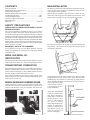
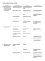
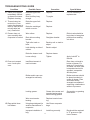
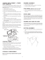
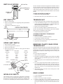
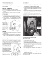
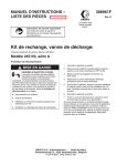
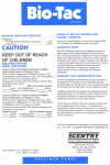
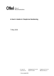
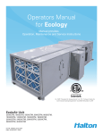
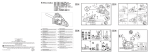
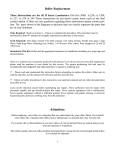
TRASH COMPACTOR
SERVICE MANUAL
MODELS
1050-J & 1051-J
MODEL
1052-B
This service manual is only for compactor models shown.
Service manuals for additional compactor models are available from your Broan representative.
Broan-NuTone LLC, 926 West State Street, Hartford, WI 53027
1 (1-800-637-1453)
CONTENTS
BAG INSTALLATION
Safety Precautions ................................................................... 2
Model and Serial No. Identification ......................................... 2
Transporting Compactor .......................................................... 2
Manually Raising and Lowering Ram ...................................... 2
Troubleshooting Guide ......................................................3 & 4
Component Replacement ............................................... 5, 6 & 7
Greasing Compactor Mechanism ............................................. 7
Wiring Diagrams ...................................................................... 8
Parts Lists .................................................................... 9 thru 12
DO NOT use plastic bags other than those which have been designed for use in this compactor. Unauthorized bags can become caught in the mechanism.
With the drawer extended to the second stop, release the container latch and swing open door. Slide bag into drawer from
front to back. Fold bag over top rim of drawer on all sides.
SAFETY PRECAUTIONS
ALWAYS UNPLUG COMPACTOR FROM WALL OUTLET
BEFORE SERVICING.
The service information is intended for use by a service technician who is familiar with proper and safe procedures to be followed when repairing electrical appliances and who is equipped
with proper tools and testing devices. Repairs attempted or made
improperly can result in personal injury or property damage. Hazards may develop from improper assembly or adjustments. While
making repairs, persons not having the proper background may
subject themselves to the risk of injury or electrical shock which
can be serious or even fatal.
PREPUNCHED HOLES
Press bag into all corners of the drawer. Smooth and shape the
bag carefully - this will prevent the bag from being torn by the
ram during compaction.
IMPORTANT - NOTE TO THE CONSUMER
If you perform service on your own Broan products, you must
assume responsibility for personal injury or property damage
which may result.
MODEL AND SERIAL NO.
IDENTIFICATION
The specification label with model and serial numbers is located
on the inside of the cabinet. It is visible after opening the drawer.
TRANSPORTING COMPACTOR
When transporting compactor, the ram should be electrically or
manually extended down into the drawer, preferably against a
load of stacked newspapers or other suitable material. If this is
not done, damage to the trunnion nut may occur.
Never transport compactor on its back or front. Damage to the
gearbox may occur. If it cannot be transported upright, it is preferable to place it on its side.
DRAWER BUTTONS
MANUAL RAISING AND LOWERING OF RAM
Unplug compactor cord from wall socket. Remove back panel.
The ram may be raised or lowered manually by using a 15/16"
socket to turn the drive screw nut. Clockwise will lower ram,
counterclockwise will raise it.
15/16”
SOCKET
2
Using buttons on side of drawer, button bag in place by using
prepunched holes in side of bag. NOTE: If you have difficulty
installing bag, move drawer to second stop by lifting front of
drawer slightly and pulling forward (place on rug or other surface to protect floor). This
will clear back of container from housing for easier bag installation.
“V” GROOVE
Swing door shut and latch
it. Bag is locked between
door flange and drawer.
When door is closed and
CONTAINER
latched properly, door
LATCH
guide “V” will be snug in
“V” groove in drawer
flange. Bag should be captured in “V” guide. Failure
to align “V” properly or to
latch drawer to door will
cause the compactor to
function improperly.
TROUBLESHOOTING GUIDE
Condition
I.
Will not run. Dead no sound. (Turn key
to start, if unit hums,
go to section III.
II. Runs continuously,
will not shut off.
III. Will not run - hums
when key held in
start position.
Possible Cause
Correction
Not plugged in securely.
Insert plug securely into
outlet.
Circuit breaker or fuse
open.
Check for condition
causing circuit breaker
or fuse to open. Correct
condition, then reset
circuit breaker or replace
fuse.
Drawer not closed.
Push drawer to close.
Loose connection.
Repair.
Defective key switch.
Replace.
Defective motor.
Test motor - replace if
necessary.
Sprocket broken.
Replace.
Chain derailed.
Reinstall chain.
Gearbox broken.
Replace.
Trunnion nut stripped.
Replace.
Key switch incorrectly
connected.
Reconnect correctly.
Defective upper limit
switch.
Replace.
Defective upper limit
switch.
Replace.
Loose connection.
Repair.
Defective motor.
Test motor - replace if
necessary.
See section on motor
replacement for test
procedure.
Plastic bag caught in
trunnion nut.
Remove plastic bag.
See section on removing
bags from tunnion nut.
Do not use bags other
than the compactor trash
bag designed and sold
by Broan for use in this
compactor.
3
Special Notes
Compactor should be on
separate 15 ampere
circuit (time-delay fuse
of circuit breaker recommended.) Do not use an
extension cord with this
appliance.
See section on motor
replacement for test
procedure.
See note in section
covering chain derailment.
Inspect trunnion nut for
any evidence of damage. If nut displays signs
of thread destruction,
replace nut, clean drive
screw and regrease.
TROUBLESHOOTING GUIDE
Condition
Possible Cause
Correction
IV. Starts and reverses
immediately. Will not
go down into drawer.
Rhythmic buzzing.
Defective upper limit
switch.
Didn’t hold key long
enough.
Replace.
V. Thermal cutout on
motor trips. (Compactor may appear to
start by itself several
minutes after last
use.) Smells hot.
Defective upper limit
switch.
Replace.
Defective centrifugal
switch on motor.
Replace.
VI. Drawer does not
open smoothly after
compactor is leveled.
Worn rollers.
Replace.
Bent roller mounting
bracket.
Straighten bracket.
Tight roller track on
base.
Bend top rail on track to
adjust.
Latch binding on side of
cabinet.
Bend to adjust.
Defective drawer track.
Replace drawer.
Loose roller(s).
Tighten.
VII. Does not compact
cans. Lacks pressure.
VIII. Bags pulled down
into drawer.
Try again.
Special Notes
It is not necessary to
replace motor.
Roller tracks should be
kept clean to keep glass
particles from wearing
out rollers.
Apply Locktite® to
threads.
Insufficient amount of
trash in drawer.
Ram does not travel to
bottom of drawer. Extends to 6" from bottom
of basket. As more trash
is deposited and unit is
operated, compaction
will take place.
Bottles and/or cans are
arranged too uniformly.
Bottles and cans should
be placed randomly in
center of drawer. Cans
and bottles neatly
arranged are capable of
supporting a tremendous
amount of pressure.
Lacking grease.
Grease drive screw and
trunnion bearing using
wheel bearing grease.
Worn rear trunnion
bearing.
Replace trunnion bearing.
Using bags designed for
another manufacturer”s
compactor.
Use Broan compactor
bags.
Improper installation of
bag.
Install bag correctly.
4
See section on greasing
mechanism.
Bag should be captured
in “V” groove on right
front of drawer.
CABINET REPLACEMENT - POWER
PACK REMOVAL
DRAWER ASSEMBLY
1. Pull out drawer until it stops.
2. Lift drawer slightly, then pull out drawer to second stop.
3. Lift drawer up and out of compactor.
A box or similar stand approximately 11” high x 15” long x 7” wide
is recommended for power pack removal. The box must be able to
support 60 lbs. or more since you will be placing the full weight of
the power pack on it.
1. Unplug compactor from socket.
2. Remove drawer assembly from cabinet.
3. Remove Air Scentry tray and control panel.
4. Remove key switch control bracket assembly. Remove back
panel.
5. Place box in cabinet and lower ram manually by turning 15/
16" nut on sprocket clockwise. Box should support weight of
power pack.
6. Remove the four 5/16" nuts supporting the power pack in the
cabinet.
7. Disconnect ground wire attached to cabinet.
8. Turn 15/16" nut counterclockwise causing power pack to lower
down out of cabinet. Pull power pack out through front of
rear of compactor.
If you are replacing the cabinet, remove remaining parts from old
cabinet and install on new. See appropriate sections of service
manual.
Reverse procedure to install power pack. Be sure the weld strip,
grommets, and spacers are in place. The lock nuts should be
torqued to 5 ft./lbs. (60 inch/lbs.). Do not overtorque.
Be careful not to pinch or nick any wires when installing power
pack in cabinet.
WELD STRIP
FOOT PEDAL (MODELS 1050 & 1051 ONLY)
1. Remove foot pedal retainers from each side of pedal.
2. Push foot pedal hinge pin out, catch foot pedal spring as it
comes free.
DOOR LINER
Remove the door from the drawer by unlatching the door and
removing the hinge pins. The door liner can be removed from the
door by removing the toe space cover and all screws holding the
door liner to the door. Slide the door liner to side of door and lift
off. (Models 1050 and 1051 will require removal of the foot pedal
prior to toe space cover.)
DRAWER AND BASE ROLLERS
All four of the rollers are secured with a 1/2" hex nut and slotted
for screwdriver. Roller nuts are installed using LocktiteR and
torqued to 20 foot pounds. Rollers are pregreased and should
require no lubricant.
BOTTOM ASSEMBLY
1. Unscrew level legs from base. Remove tee nuts that legs screw
into.
2. Remove screws securing bottom assembly to the cabinet.
3. Lower the bottom down into the cabinet, back end first, then
bring it up and out through the notches in the bottom flange
of the cabinet.
GROMMETS
SPACERS
POWER PACK
MOUNTING
LOCK NUTS
CONTROL PANEL
On units with a bag storage compartment, removal of the storage
compartment will make replacement of the control panel easier.
1. Remove drawer assembly.
2. Remove the four screws securing the air scentry tray and the
bottom of control panel to the cabinet.
3. Pull bottom of control panel out slightly and then up.
When installing the control panel, make sure lip on inside of
control panel snaps behind the bend in the control panel bracket.
STORAGE COMPARTMENT
Remove two screws on rear of compactor and the two 5/16" hex
head screws inside the storage compartment. Slide compartment
back and lift off.
5
SWITCH LOCATIONS
KEY SWITCH
the door. Another switch located against the interlock switch is
the door. Another switch located against the interlock switch is
to provide the “No-Jam” circuitry function. This switch is normally open and bypasses the interlock to provide “No-Jam” capability. It can be replaced in the same manner as the interlock
switch.
INTERLOCK
SWITCH
UPPER LIMIT
SWITCH
TO REPLACE INTERLOCK SWITCH
1. Remove air scentry panel assembly.
2. Disconnect leads one by one and attach to new switch.
KEY SWITCH
TRUNNION NUT
1. Remove control panel.
2. Remove two hex head screws supporting control panel bracket
with 5/16" socket.
3. Pull bracket out and remove switch.
1. Remove back panel, drawer assembly and air scentry panel.
2. Lower ram manually to approx. 10-1/2" from the bottom assembly onto box or stand described in “CABINET REPLACEMENT/POWER PACK REMOVAL” section.
3. Remove screws from nut retainer.
4. Raise ram assembly slightly by hand and remove nut.
NOTE: Count the number of revolutions to spin off nut. TRUNNION must be reinstalled to same position.
5. Reinstall trunnion nut and retainer.
KEY
SWITCH
CONTROL PANEL BRACKET
CONTINUAL STRIPPING OF TRUNNION NUT:
POSSIBLE CAUSES:
1. Incorrect assembly of trunnion assembly.
2. Transporting compactor incorrectly.
3. Burr on main drive screw; sharp edge on lead-in thread.
4. Upper limit switch adjustment.
TR-RED
V-BLACK
Y-BLUE
UPPER LIMIT SWITCH
1.
2.
3.
4.
REMOVING PLASTIC BAGS FROM
TRUNNION NUT
Remove drawer assembly.
Lower ram to gain access to switch.
Remove air scentry tray.
Remove hex head screw with 5/16" socket, pull switch down
and disconnect wires.
Check
Switch not
Switch
Continuity
Activated
Activated
3 to 1
closed
open
2 to 1
open
closed
6 to 1
open
open
3 to 4
open
open
6 to 4
closed
open
5 to 7
open
closed
2-ORANGE
Only the trash compactor bags specifically designed and sold by
Broan for use in the compactor should be used. Regular plastic
garbage bags used in place of the Broan bags may be drawn into
the mechanism. Removal of those bags is not covered by the
warranty.
To remove bag from trunnion nut:
1. Remove back of compactor.
2. If possible to slide drawer slightly, remove the door by sliding
out the two hinge pins and then prying the door over the lip
on the drawer.
3. Liberally spray drive screw and trunnion nut with WD-40R or
similar.
4. Use 15/16" socket, and extension, and a 16" ratchet (for leverage) and manually turn the drive screw clockwise. (See section on manually raising and lowering ram.) By turning the
drive screw clockwise, you will help back the bag out of the
trunnion nut.
5. After removing bag, clean drive screw and regrease it with
wheel bearing grease.
1-STRIPED BLUE
3-VIOLET
5-YELLOW
6-YELLOW
4-BROWN
7-BROWN
DRIVE SCREW
INTERLOCK SWITCH
The interlock switch is a single-pole, single-throw momentary
type. It is located on the right side behind the air scentry panel.
Its contacts are normally open. the contacts close when the door
is closed. It is activated by the actuator located on the back of
6
1.
2.
3.
4.
Lower ram manually approximately halfway.
Remove sprocket.
Remove 1/4" drive pin. Slide off washers.
Lift ram, causing drive screw to slide out of the motor trunnion bearing. Support motor/gearbox assembly since it is now
free to pivot. Unscrew drive screw from front trunnion assembly.
TRUNNION BEARING
GEARBOX
1. Remove sprocket and drive pin.
2. Pull out trunnion bearing.
Grease trunnion bearing inside and out with wheel bearing grease
prior to reinstalling.
1. Lower ram manually until there is approximately 11" to 12"
between the ram and the bottom assembly.
2. Remove the four 3/8" nuts securing motor to gearbox, slide
motor out and rest it on the front trunnion assembly.
3. Turn sprocket until two holes in sprocket line up with the two
socket head cap screws that hold the gearbox to the motor
trunnion.
4. Remove the two socket head cap screws with a 5/32" hex key.
NOTE: The screws thread into 2 nuts which rest in slots in the
motor trunnion. Be careful not to lose the 2 nuts when the
screws are removed.
5. Tilt gearbox forward and remove chain. Lift gearbox out.
When installing gearbox, Locktite® should be applied to the socket
head cap screw nuts.
MOTOR TRUNNION
1. Remove motor, gearbox, spocket, and screw guard.
2. Use 13/16" wrench to remove bolts securing links to motor
trunnion.
When reinstalling, bolts should be torqued to 45 foot pounds.
SPROCKET
1. Line up one of the 3/8" holes in the sprocket with the 3/8"
hole in bottom center of gearbox. Insert 3/8" steel pin or bolt
through sprocket hole into front and rear gearbox holes.*
2. Loosen and remove 15/16" nut on the drive screw. When
reinstalling torque to 65 foot pounds and apply Locktite® to
threads.
*If the sprocket is
too damaged to be
INSERT
able to use on of the
3/8” DIA. PIN
holes to secure it,
chip away the remaining sprocket, remove the drive pin
and then insert a
screwdriver through
the hole to provide a
means of keeping the
drive screw from
turning.
5/32”
HEX KEY
CHAIN
1. Turn sprocket until two holes in sprocket line up with socket
head cap screws.
2. Remove socket head cap screws and tip gearbox/motor assembly to remove chain. NOTE: The screws thread into 2
nuts which rest in slots in the motor trunnion. Be careful not
to lose the 2 nuts when the screws are removed.
When reinstalling socket head cap screws, be sure Locktite® is
applied to the nuts.
Chain Derailment: Loose chains. Sometimes a chain will derail
because trash which flew up above the ram during compacting
fouled the chain. Newspaper or a paper bag should be placed on
top of glass bottles before compacting to prevent this.
If continual derailment of the chain is a problem, inspect both
sprockets for worn or missing
teeth. Inspect gearbox mounting and mounting plate. If the
mounting screws are loose,
gearbox movement may be the
cause. If the gearbox mounting
plate is bent where it meets the
motor trunnion, either straighten or replace the gearbox.
Some chain looseness is normal and may increase as the
compactor is used. Seldom
does the chain “stretch” to the
point where it is too loose.
GREASING COMPACTOR
MECHANISM
7
1. Unplug compactor from wall outlet.
2. Remove drawer assembly from compactor.
3. Remove back of compactor and lower mechanism manually
by turning 15/16" nut on sprocket clockwise.
4. Line up one of the holes in the black sprocket with the hole in
the gearbox. Insert a 3/8" bolt or pin to keep sprocket from
turning and remove the 15/16" nut.
5. Slide off sprocket and washer.
6. Drive out the drive pin, slide off thin washer and pull out
trunnion bearing.
7. Grease trunnion bearing everywhere, inside and out, with
regular wheel bearing grease.
8. Reassemble unit in reverse procedure. When reinstalling 15/
16" nut, be sure to apply a drop of Locktite® or equivalent to
the threads of the 15/16" nut.
Apply grease to length of drive screw and a dab to the scissor
links at the pivot points.
BLACK GRAY
RED
GREEN
MOTOR
Before motor is removed, it should be tested to be sure it is
inoperative. Check the continuity of the motor.
ORANGE
CHECK CONTINUITY
Black to Orange
Red to Orange
Gray to Orange
Green to Motor Frame
1.
2.
3.
4.
If open, replace motor
If open, replace motor
If open, replace motor
If open, inspect wire to
be sure it is properly
attached to motor
frame
Lower ram manually until there is approximately 7" between
the bottom assembly and the ram.
Disconnect molex connector from motor to wire harness.
Using a 3/8" nut driver or socket, remove the four nuts holding the motor to the gearbox. Remove air scentry tray and pull
motor out through front of compactor.
Install motor in reverse procedure.
EMERSON MOTOR
93030201
CENTRIFUGAL SWITCH
(USED ON EMERSON MOTOR)
BROWN
YELLOW
WHITE
BLUE
WIRING SCHEMATIC
SCHEMATIC SHOWS UNIT AT END
OF CYCLE - IN TOP POSITION
DRAWER OPEN
R
TR
L1
GN
W
GN
BK
OFF-ON
4
C
START
BL
KEY
SWITCH
NO
NC
C
R
NO
2 BK
NC
OR
BR
C
Y
NC
INTERLOCK
SWITCH
1
R
NO
HELD CLOSED
NO
OL
CCW START DOWN
RUN
3 GY
NC
MOTOR
NO
TOP LIMIT
SWITCH
1
2
3
4
5
NC
BR 5 OR
C
SPEED
SWITCH
Y
CW START UP
USAS SYMBOLS
NC
HELD OPEN
NO
GN
NO
BL/W
C
BL/W
BR
Y
V
W
SAFETY SWITCH
GN
BK (or BR)
V
COMPACTOR
SCHEMATIC
N
NC C
NO
C
Y
V
TR
C
NO
NCNC
OFF - ON
START - RUN
KEY SWITCH
MOTOR
PLUG
8
C
NC
C
TOP LIMIT
SWITCH
NO
MODELS 1050-J,
1051-J, 1052-B
Service Parts
Page 1 of 4
ITEM NO.
1
2
4
5
6
7
9
10
12
13
14
15
17
18
19
22
23
24
25
26
27
28
30
38
40
41
42
43
45
PART NO.
92008659
93150459
93150458
92005968
93110436
93100402
93110619
93110934
93110694
93090903
93090904
93090944
91012250
93030117
93260451
93110936
93110935
93110695
91009865
91006357
93470012
OPTIONAL
92007052
93260447
93420453
93380623
93110447
93770026
93110572
93110698
93110854
93710014
93150487
99270461
91008065
93260492
91007999
45
45
DESCRIPTION
Back Panel
Screw, #8-18 x 1/2 PH. TR. HD. - Standard
Screw, #10-16 x 3-1/2 PH. TR. HD. - Standard
Control Panel Bracket
Guide Button
Rubber Bumper
Control Panel (Model 1050)
Control Panel, White (Model 1051)
Control Panel (Model 1052)
Control Panel Insert (Model 1050)
Control Panel Insert (Model 1051)
Control Panel Insert (Model 1052)
Air Scentry Panel / Switch Assembly
Key Switch
Nut, Hex 5/8-32
Key, Knob-Type (Model 1050)
Key, Knob-Type (Model 1051)
Key, Knob-Type (Model 1052)
Cabinet, (Includes Mounting Stud Strips 91007999)
Bottom Assembly (Includes Rollers 93470012)
Rollers
Cutting Board (order Model #1004)
Storage Compartment
Nut, Whizlock 5/16-18
5/16-18 Snap-in Tee Nut
Level Leg
Pad for Level Legs
Cord Set
Storage Compartment Door (Model 1050)
Storage Compartment Door (Model 1051)
Storage Compartment Door (Model 1052)
Track Filler
Screw, #10-24 x 3/8 SL HLX WS T-Point
Cord Clamp
Rubber Grommets (Includes Spacers) Pkg. of Four
Nut, Hex Lock 5/16-18
Mounting Stud Strip Assembly
9
70
MODELS 1050-J,
1051-J, 1052-B
Service Parts
Page 2 of 4
FRONT
66
65
87
68
89
69
87
ITEM NO.
65
66
67
68
69
70
71
73
77
78
80
82
83
84
85
86
87
88
89
Not shown
PART NO.
91014197
99260330
93170263
93390127
93390126
93271136
93150506
93260443
93420442
93710029
93380632
92004582
91005183
92004584
91009243
93170265
93710026
93710030
93160408
93770071
DESCRIPTION
Switch Assembly, Top Limit (Includes Switch)
Nut, Kep #10-32
Bolt - Special 7/16-20 x 1-5/8
Top Rail Assembly, Right
Top Rail Assembly, Left
Wire Clamp
Screw, #12-24 x 5/16 SL HX WS T-Point
Push-On Retainer
Pin, Upper Rear
Spacer, Rail, Rear
Shaft, Lower 7.218 Long
Link, Main 2-Hole
Link Assembly, Peened
Ram Mounting Channel
Ram Platen
Cap Screw, Hex 5/16-18 x ½
Spacer, Ram Front
Spacer, Ram Rear
Screw, #10-32 x .625 SL HEX HD
Wire Harness
10
71
126
125
MODELS 1050-J,
1051-J, 1052-B
Service Parts
Page 3 of 4
ITEM NO.
66
67
82
83
99
100
102
105
106
107
108
109
113
114
115
116
119
120
121
122
123
124
125
126
127
128
129
156
157
PART NO.
99260330
93170263
92004582
91005183
91009323
91009324
93030201
93450006
93260439
93250908
93110434
93420441
93470006
93180002
93250907
93380619
93250913
93110458
93300442
93260457
93150487
91011704
93840003
92008438
93420558
93110972
93260458
93710027
93150506
129
124
127
DESCRIPTION
Nut, Kep #10-32
Bolt, Special 7/16-20 x 1-5/8
Link, Main 2-Hole
Link Assembly, Peened
Motor (Includes Centrifugal Switch & Pinion)
Gear Box Assembly
Centrifugal Switch
Chain, Endless
Nut, 5/8-18 Semifin Jam
Washer, .63 I.D.
Sprocket, 50-Tooth
Drive Pin
Reverse Thrust Bearing
Cap Screw, Socket HD #10-32 x 1/2
Washer, .81 I.D.
Main Drive Screw
Washer, Thrust
Trunnion Bearing
Motor Trunnion
Nut, Hex #10-32
Screw #10
Sheet Metal Trunnion (Includes Item Nos. 124, 125, 126, 127 & 157)
Trunnion Nut
Trunnion Nut Retainer
Screw Guard Guide
Main Screw Guard
7/16-20 Hex Lock Nut
Washer Spacer Trunnion
Screw, #12-24 x 5/16 SL HX WS T-Point
11
157
MODELS 1050-J,
1051-J, 1052-B
Service Parts
Page 4 of 4
Model 1052
154
153
158
149
ITEM NO.
2
19
24
130
131
OPTIONAL
152
153
154
PART NO.
93150459
93470012
93260447
93042445
91011634
91011624
93420449
91011726
93260454
93100511
93370334
93370354
92007833
92007053
93110515
93110514
93650041
93300419
93300424
93650008
93300420
99230342
91006230
93480009
93140143
93110516
93650057
93650018
91009957
93620008
99230340
99111098
158
99260502
132
133
134
135
139
140
142
143
144
145
146
147
148
149
150
151
DESCRIPTION
Screw, 8-18 x 1/2 PH. TR. HD. - Standard
Rollers
Nut, Whizlock 5/16-18
Owners Manual (Models 1050 & 1051)
Door Liner Assembly (Includes Item No. 135) (Models 1050 & 1051)
Door Liner Assembly (Includes Item No. 135) (Model 1052)
Hinge Pin
Drawer Assembly (Includes Rollers 93470012)
Nut, Tinnerman, Type 8Z-U
Interlock Actuator
Handle (Models 1050 & 1051)
Handle (Model 1052)
Door (Models 1050 & 1051)
Door (Model 1052)
Toe Space Cover (1050 & 1051)
Toe Space Cover (Model 1052)
Side Door Trim (Models 1050 & 1051)
Side Door Trim (Model 1052)
Top Trim (Model 1052)
Bottom Door Trim (Models 1050 & 1051)
Bottom Door Trim (Model 1052)
Rivet, Pop, SD 41 BS 1/8
Foot Pedal and Push Rod Assembly (Models 1050 & 1051)
Hinge Pin, Foot Pedal (Models 1050 & 1051)
Spring, Foot Pedal (Models 1050 & 1051)
Retainer, Foot Pedal (Models 1050 & 1051)
Door Panel, Black-Biscuit (Models 1050)
Door Panel, Stainless Steel (Model 1052)
Door Panel, Black-White (Model 1051)
12-Pack Compactor Bags
Pop Rivet
Bag Button
Grease for Power Pack & Screw (Wheel Bearing Grease)
Grease Lubriplate
Locktite®, #271
Nut Sheet Metal
12
93042469G