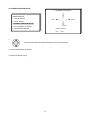
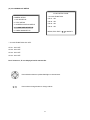
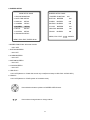
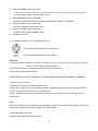
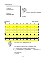
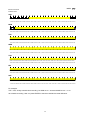
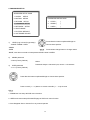
1
Thank you for purchasing our product.
Please read this User’s Manual before
using the product. Change without Notice
4 Channel Digital Video Recorder
User’s Manual
1
Safety Precautions
CAUTION
RISK OF ELECTRICAL
SHOCK. DO NOT OPEN !
CAUTION: TO REDUCE THE RISK OF ELECTRICAL SHOCK,
DO NOT REMOVE COVER (OR BACK), NO USER
SERVICEABLE PARTS REFER SERVICING TO
QUALIFIED SERVICE PERSONNEL.
This label may appear on the bottom of the unit due to space limitations.
The lightning flash with arrowhead symbol, within an equilateral
triangle, is intended to alert the user to the presence of insulated
dangerous Voltage within the product’s enclosure that may be
sufficient magnitude to constitute risk of electrical shock to persons.
The exclamation point within an equilateral triangle is intended to alert
the user to the presence of important operation and maintenance
(servicing) instructions in the literature accompanying the appliance.
WARNING: TO PREVENT FIRE OR SHOCK HAZARD, DO NOT
EXPOSE UNITS NOT SPECIFICALLY DESIGNED FOR
Attention: installation should be performed by qualified service
Personnel only in accordance with the National Electrical Code or
applicable local codes.
Power Disconnect. Units with or without ON-OFF switches have
power supplied to the unit whenever the power cord is inserted into
the power source; however, the unit is operational only when the
ON-OFF switch is the ON position. The power cord is the main power
disconnect for all unites.
“CAUTION: Danger of explosion if battery is incorrectly replaced.
Replace only with the same or equivalent type recommended by the
manufacturer. Dispose of used batteries according to the
manufacturer‘s instruction.”
Warranty
and Service
During the warranty period (one year), we will repair or replace the
DVR free of charge.
Be sure to have the model number, serial number and vendor stick on
hard disk for service representative.
2
About this document
Before installing stand alone DVR, be sure to thoroughly review and follow the instructions in this Users
Manual. Pay particular attention to the parts that are marked NOTICE.
Also, when connecting with external application, first turn the power OFF and follow manual
instruction for appropriate installation.
Before reading this document
1. This document is intended for both the administrator and users of stand alone DVR Model.
2. This manual contains information for configuring, managing and using stand alone DVR Model.
3. To prevent fire or electrical shock, do not expose the product to heat or moisture
4. Be sure to read this manual before using stand alone DVR Model.
5. For questions and technical assistance of this product, contact your local dealer.
►Strong recommendation on installation of the DVR unit
1. Check electricity at the place you want to install the DVR unit is stable and meets our electricity
requirements.
Unstable electricity will cause malfunction of the unit or give critical damage to the unit.
2. Several chips on the main board of the DVR unit and hard disk drive inside the unit generate heat,
and it must be properly discharged.
Do not put any objects just beside exhaust port(fan) on the left side of the unit and do not close up an
opening (fresh air in-take) on the right side of the unit..
3. Put the DVR unit at well-ventilated place and do not put heat-generating objects on the unit.
When it is installed inside 19 inch mounting rack together with other devices, please check built-in
ventilation fan of the rack is properly running.
3
Content
Safety Precautions………………………………………………………………………………………………… 2
About this document………………………………………………………………………………………………. 3
Before reading this document……………………………………………………………………………………. 3
Unite Description of Front Panel………………………………………………………………………………… 5
Unit Description of Rear Panel……………………………………………………………………………………6
Installation………………………………………………………………………………………………………….. 7
Function Setup…………………………………………………………………………………………………….. 15
Login…………………………………………………………………………………………………………. 15
Basic Operation…………………………………………………………………………………………….. 4
USB Data Read and Networking………………………………………………………………………………... 39
Record Time Table: 80 GB HD………………………………………………………………………………….. 49
VGA Description (Optional) ……………………………………………………………………………………… 50
Additional…………………………………………………………………………………………………………….51
4
Unit Description of Front Panel
4 split screen
1 ~ 4 full screen / password
Channel freezer and zoom x2
Channel Sequence / Water Mark (PTZ mode) / System Information
MENU button / ESC MENU exit button / LOCK key lock button
BACKUP Data backup button / T-SRH time search playback button
Value change button
PLAY playback button / REC. record button
Direction UP / Down,
Direction Left / Right
Record and play stop,
Playback forward or reverse.
Playback pause / steps.
ENTER / Audio ON or OFF
Function LED light display
Playback forward / reverse
Function item change shuttle.
USB. Data backup or firmware update
Remote controller IR
5
Unit Description of Rear Panel
Power cord in 12V/5A, power switcher (ON / OFF)
Camera 1 ~ 4 in and
75 Ohm ON/OFF (high/low adjust)
looping out
VGA output. PC monitor connector.
Audio channel
(Optional)
input x 1 / output x 1
LAN. Network connector
Main Monitor /
S-Video (Y/C)
RS-485 connector
RS-232 connector (ISP. For RD control)
Alarm connector
Notice: Reboot DVR after installing any device.
6
Installation
Procedure
1) Camera Connection
DC
LEVEL
Connect the camera to the CAMERA INPUT
V.P
CH1
CH2
CH3
VIDEO
CH4
DC
MONITOR
on the Rear Panel of the 4 CH DVR.
CH1
CH2
CH3
CH4
VIDEO
LENS
AC24V/DC12
Rear part of CAMERA
2) Monitor Connection (Composite Connection
Method)
Connect the monitor to the MONITOR OUT on
CH1
CH2
CH3
CH4
CH1
CH2
CH3
CH4
MONITOR
the Rear Panel of the 4 CH DVR.
VIDEO A
IN
OUT
3) Monitor Connection
Connect S-VIDEO Monitor to MONITOR OUT
CH1
CH2
CH3
CH4
CH1
CH2
CH3
CH4
MONITOR
on the Rear Panel of the 4 CH DVR.
VIDEO A
IN
OUT
4) Sensor Connection
Connect the Sensor to the SENSOR INPUT/
OUTPUT on the Rear Panel of the system
1. ALARM 1
2. ALARM 2
3. ALARM 3
4. ALARM 4
23. ALARM NC
24. ALARM NO
13,12,11,10,9,8,7,6,5,4,3,2,1
25. ALARM COM
25,24,23,22,21,20,19,18,17,16,15,14
5. ~ 19. GND
◆Relay output : COM+NC, COM+NO
◆Alarm input : Short-circuit between Alarm1 ~ 4 and GND is recognized as alarm by default.
Alarm 1 ~ 4 will be corresponding to Camera 1 ~ 4.
NC = Normal Close. NO = Normal Open.
7
NOTICE: Sensor input is RECOGNIZED as LOW when alarm signal is on a level with GND, and it is
recognized as HIGH when alarm signal is FLOATING or 5V. Following is internal circuit.
5
V
Internal Circuit
D1
Thus, there is a danger of damage, when the sensor input goes to a Negative level or voltage higher than 5V.
5) Network Connection
DVR connects to LAN
ETHERNET
rks
TERATRAY CONNECTION
◆To view video image on the computer through internet with DVR view software.
8
5) HDD connection
1
How to connect single HDD
2
I/O BOARD
How to connect 2 HDD
I/O BOARD
1
2
1
1
MASTER
tie
2
2
MAIN BOARD
HDD1
3
MASTER
MAIN BOARD
3
HDD
SLAVE
HDD2
3
Set the drive jumpers as specified by hard disk drive manufacturer.
1.
Make sure the HDD is MASTER.
2.
Make sure the cable connector is
1.
correct.
3.
Set the drive jumpers as specified by hard disk drive manufacturer.
2.
Please check the HDD panel for
Master set up.
Make sure the HDD is MASTER and
SLAVE.
Make sure the cable connector is
correct.
3.
Please check the HDD panel for
Master and Slave set up.
Notice:
-Hard Disk Master and Slave jumper pin must right, otherwise it makes DVR work fault.
Hard Disk lab testing table:
Brand
Model
Capacity
Seagate
Barracuda
80 GB
IBM
DeskStar
80 GB
WD2000
Caviar
200 GB
Hitachi
DeskStar
80 GB
Maxtor
MaxLineII
300 GB
9
Notice
Picture
Full screen or split screen display
Press
button, to display 4 split screen.
Press numeric buttons
to display the desired camera image in full screen.
1.) FREEZE Mode
1. In live mode press
2. Press
(FREEZE) button to freeze image.
again to cancel freeze mode.
2.) Zoom Mode(Display Enlargement.)
Go to full screen mode with numeric buttons at live or playback
mode, then press ZOOM button to display screen Enlargement.
Use
button to move position.
3.) Auto Mode
Press
(AUTO) button to start screen auto sequencing, and press it again to cancel auto mode.
4.) W.MARK. Water Mark mode.
Water Mark on to check if the data has modify.
5.) INFO (System Information). Auto disappear after 2 minutes if no any button operating.
** SYSTEM INFORMATION **
1. Network IP address
1.IP ADDR:
2. Network IP gateway
2.GATEWAY:
3. Network IP netmask
3.NETMASK:
4. Network user amount
4.NET USER:
5. Hard disk capacity
5.HDD SIZE:
6. Hard disk used percentage
6.HDD USED:
7. First hard disk status
7.STATUS1
8. Video format
8.STATUS2
9. System running time
9.UPTIME
10. System version
10.VERSION:
10
6.) BACKUP. Image backup mode.(Image back up must be done on playback mode only.)
Locate the playback point of which you want. Press BACKUP, back up menu shows:
CDRW / USB
CDRW
BACKUP MENU
USB
BACKUP MENU
BACKUP MENU
START BACKUP TO CDR
CDR WRITE SPEED x1,x2,x3
FORMAT USB
FORMAT USB
START BACKUP TO CDR
START BACKUP TO USB
CDR WRITE SPEED
START BACKUP TO USB
USB:
The BACKUP CAUTION window pop-up. Press ENTER to begin data back up. Capacity of USB device is not
limit.
On playback mode, presses BACKUP:
Lower-Right corner of the screen:
** BACKUP CAUTION **
THE ORIGINAL BACKUP FILE
WILL BE KILLED.
PRESS [ENTER] TO BACKUP.
PRESS [BACKUP] TO CANCEL.
xxx K
xxx K (Presently back up progress)
Important:
If DVR cannot detect USB device, please format it to FAT or FAT 32 on PC OS.
When the file is opened from a CF card, only DVR images will appear, but without sounds.
Additional:
During playback, USB device is full or user press BACKUP button screen display a “PAUSE” caption, User
takes out the USB device to computer USB slot then save data to hard disk. After re-insert USB device to
DVR slot, user press BACKUP again. Press ENTER to continue backup or backup button to cancel.
** BACKUP CAUTION **
PAUSE
THE ORIGINAL BACKUP FILE
WILL BE KILLED.
PRESS [ENTER]
TO BACKUP.
PRESS [BACKUP] TO CANCEL.
PS: NetViewer software auto copied to USB device when data backup. See the USB Data Read and
Networking pages.
11
Compatible USB: Transcend 256 MB, 1 GB / A-DATA, 512MB / USB Flash Drive 128 MB /
Intelligent Stick 256 MB / SOLOMON 128 MB / ISTEC 1GB.
CD-RW:
xxx K (Presently back up progress)
Press BACKUP to stop saving. Or wait for CD is full done.
xxx K
Data only read in Netviewer.
7.) Key Lock function
>On the Live mode, press
(lock), Only, numeric, freeze, auto, and zoom buttons could work.
Press lock key again to enter the login-in window. Enter admin or user password to unlock.
Key lock function only accept password correct log in even re-boot DVR power.
8.) AUDIO function ))))
))))
xxxxxxxxx
ENTER / AUDIO button
Audio playback: AUDIO ,
) ))))displays on the Upper-left of screen. At that time, audio
will playback. Press it again to turn it off.
Notice
Audio playback only on normal( x 1 ) playback.
9. NETWORK Playing
NETWORK PLAYING
PASSWORD : (*****)
ENTER PASSWORD TO TERMINATE
1. When the admin do playback mode on AP (Net Viewer), user can terminate it after into password of DVR.
On AP client, admin needs to connect again.
2. When AP on playback mode, DVR is on playback mode also.
12
Playback
1. Playback Mode
1) Press
PLAY
button to begin playback. (System playback the images backward)
2. T-SRH button
MAIN PLAY PAGE
1) T-SRH: Playback by time search.
Press T-SRH button to active playback function.
1.MASTER TIME LIST
2.SLAVE TIME LIST
3.MASTER EVENT LIST
Press direction button
4.SLAVE EVENT LIST
UP/DOWN to choose
5.GOTO DATE: 2004/12/31
items.
6.GOTO TIME: 12:12
7.GOTO PLAY
1) TIME LIST (Playback image by Time-Search): Recorded images list (by hours)
TIME LIST
Y/M/D H:M
Y / M / D H : M (Beginning of recording time)
Y/M/D H:M
Y / M / D H : M (End of recording time)
Every playback data list displays by an hour.
No page display limit. 10 items display on each page.
Press direction button UP/DOWN to choose items.
Press
values change button to change to previous / next page.
Notice:
Every playback data list displays by an hour, but if user finds out like:
1. 10:00 ~ 10:12
2. 10:12 ~ 11:00
Reason: 1. Hard disk is full. 2. User change record mode setup.
13
2) EVENT LIST (Alarm List): Event source- Video loss / Alarm trigger / Motion / Record
EVENT LIST +10
NO Y / M / D H : M CH EVENT
10 items display on each page / Total 5000 items display for 500 pages. When event list is out of compass,
the total items are less then 5000.
NO Y / M / D H : M CH EVENT
>Event happens time and list.
CH: Event Channel Display.
>1 CH ~ 4 CH
+10 : Display pages by 10 units / +100 : Display pages by 100 units / +1000 : Display pages by 1000 units.
- Press direction button left and right to change +10 / +100 / +1000
Event type.
>Includes Motion / Alarm / V-Loss / Record / Power On / Event Full / Network (Network total users,
include log in and log out.)
Press direction button UP/DOWN to choose items.
Press
values change button to change page. Press ENTER to start
playback.
>Special time search playback:
Go TO DATE:2002/12/12
-Choose year / month / day
>Press direction button Left / Right to choose items, press values change button
to change value.
GOTO TIME:12:12
-Choose hour and minute
>Press direction button Left / Right to choose items, press values change button
GOTO PLAY
-Press ENTER button to start playback.
Notice: Playback speed change by
or shuttle. Speed is x 1, x 2, x 4, x 8, x 4.
14
to change value.
Function Setup
LOGIN
1) Press
MENU
button to enter into menu. You could do the system function setup in MENU.
2) Password enter window pop-up:
CHECK PASSWORD MENU
PASSWORD (*****)
Default password (Account-Admin) : 44444
Default password (Account-User) : 11111
3) Press numeric (1 ~ 10 )button or remote controller ( 1 ~ 10 )to choose password.
4) Remote controller function buttons are same as DVR panel function buttons.
15
Basic Operation
Press MENU button to enter MAIN SETUP PAGE.
MAIN SETUP PAGE
1. HDD INFORMATION
2. DATE-TIME SETUP
3. DISPLAY
SETUP
4. CAMERA
SETUP
5. BUZZER
SETUP
6. RELAY
SETUP
7. SYSTEM
SETUP
8. ADVANCED SETUP
MENU, ESC: EXIT, ENTER: RUN
1) Use direction button up/down
2) Press
button to select setup item.
button to enter into sub-menu function setup.
3) Press sub-menu item with direction button up/down
or left/right
button.
And change the value with
values change button or turn inner-shuttle.
4) Press ESC to go back to main / sub menu or exit menu.
Notice:
1. ADMIN level can setup all DVR menu functions.
2. USER level cannot setup ADVANCED page of DVR main menu function.
3. Auto disappear after 4 minutes if no any button operating.
16
1. HDD INFORMATION
MAIN SETUP PAGE
1. HDD INFORMATION
POSITION SIZE USED BRAND
2. DATE-TIME SETUP
MASTER
3. DISPLAY
SETUP
LAST TIME
4. CAMERA
SETUP
SLAVE
5. BUZZER
SETUP
LAST TIME
6. RELAY
SETUP
7. SYSTEM
SETUP
MENU, ESC: EXIT,
8. ADVANCED SETUP
MENU, ESC: EXIT, ENTER: RUN
- 2 hard disk information display.
Information display: POSITION SIZE USED BRAND
>POSITON: Master / Slave
>SIZE: Hard Disk capacity. xxGB. Maximum display is 999MB
>USED: 00 ~ 100 %. Hard disk overwrites 100 ~ 199 %.
>BRAND: DVR auto detect hard disk brand.
>LAST TIME: The last record time display.
17
:PAGE
2. DATE-TIME SETUP
MAIN SETUP PAGE
1. HDD INFORMATION
DATE-TIME SETUP PAGE
2. DATE-TIME SETUP
1. DATE 2000 / 00 / 00
3. DISPLAY
SETUP
2. TIME
4. CAMERA
SETUP
3. FORMAT
5. BUZZER
SETUP
3. DISPLAY AT xx LINE(S)
6. RELAY
SETUP
7. SYSTEM
SETUP
MENU, ESC:EXIT,
:MODIFY
8. ADVANCED SETUP
MENU, ESC: EXIT, ENTER: RUN
1. DATE
2. TIME: > Use direction button up/down choose position, values change button to change date and time
values. Do not need to stop hard disk working (Play or record).
3. FORMAT:
YY/MM/DD, MM/DD/YY, DD/MM/YY, YY/ENG/DD, ENG/DD/YY, DD/ENG/YY, YYYY/MM/DD,
MM/DD/YYYY, DD/MM/YYYY, YYYY/ENG/DD, ENG/DD/YYYY, DD/ENG/YYYY.
Y=Year. M=Month. D=Day. ENG=Month display in English.
4. DISPLAY AT xx LINE(S)
-Date and Time position on screen xx line(s). 00 ~ 23.
-. Day and time change
Press direction button up/down/left/right to choose items or move date-time position.
Press
values change button to change values.
18
3. DISPLAY SETUP
MAIN SETUP PAGE
DISPLAY SETUP PAGE
1. HDD INFORMATION
1. DATE-TIME
ON
2. DATE-TIME SETUP
2. CAMERA TITLE
ON
3. DISPLAY
SETUP
3. PB DATE-TIME
ON
4. CAMERA
SETUP
4. PB CAMERA TITLE
ON
5. BUZZER
SETUP
5. PB DUMMY CAMERA
ON
6. RELAY
SETUP
6. DVR STATUS
ON
7. SYSTEM
SETUP
7. BORDER COLOR
WHITE
MENU, ESC:EXIT,
:MODIFY
8. ADVANCED SETUP
MENU, ESC: EXIT, ENTER: RUN
1. DATE-TIME: Date and Time caption display mode on or off setup.
>ON / OFF
2. CAMERA TITLE: Camera Title caption display mode on or off setup.
>ON / OFF
3. PB DATE-TIME: Play back date and time caption display mode on or off setup.
>ON / OFF
4. PB CAMERA TITLE: Play back camera title caption display mode on or off setup.
>ON / OFF
5. PB DUMMY CAMERA: To clear dummy image if channel input not up to 4.
>ON / OFF
6. DVR STATUS: DVR system, record, playback, audio caption display mode on or off setup.
>ON / OFF
7. BORDER COLOR: Border color WHITE / DARK / BLACK / GRAY.
Press direction button up/down to choose the desired item.
Press
values change button to change values.
19
4. CAMERA SETUP
MAIN SETUP PAGE
CAMERA SETUP PAGE
1. HDD INFORMATION
1. COLOR SETUP
2. DATE-TIME SETUP
3. DISPLAY
SETUP
4. CAMERA
SETUP
5. BUZZER
SETUP
6. RELAY
SETUP
7. SYSTEM
SETUP
2. TITLE SETUP
3. SCREEN POSITION SETUP
4. V-LOSS DISPLAY SETUP
5. VIDEO MASK SETUP
MENU, ESC: EXIT, ENTER: RUN
8. ADVANCED SETUP
MENU, ESC: EXIT, ENTER: RUN
COLOR SETUP PAGE
(1.) COLOR SETUP
** CHANNEL NUMBER 01
1. BRIGHTNESS 00
CAMERA SETUP
2. CONTRAST
1. COLOR SETUP
2. TITLE SETUP
3. SCREEN POSITION SETUP
3. SATURATION
00
4. HUE
00
5. GAIN
4. V-LOSS DISPLAY SETUP
00
00
>>DEFAULT RESET<<
5. VIDEO MASK SETUP
MENU,ESC:EXIT,
:MODIFY
COLOR SETUP : Adjust Camera Image. Only on live mode adjustable.
CHANNEL NUMBER
: Select camera 01 ~ 04
BRIGHTNESS
: Adjust screen brightness
(-30~ +30)
CONTRAST
: Adjust color contrast
(-20~ +42)
SATURATION
: Adjust color saturation
(-34~ +22)
HUE
: Adjust color hue
(-24~ +24)
GAIN
: Adjust image signal level
(-32~ +32)
>>DEFAULT RESET<< : Press ENTER button to reset DVR values.
Press direction button up/down to choose items.
Press
values change button to change values.
>Right adjustment of each element in COLOR setup will increase picture quarterly displayed. We recommend
you to adjust each element of COLOR SETUP for cameras and monitor to be connected to the DVR unit.
20
(2.) TITLE SETUP: Input TITLE of each camera. 9 characters can be input.
TITLE SETUP PAGE
CAMERA SETUP
1. COLOR SETUP
2. TITLE SETUP
3. SCREEN POSITION SETUP
4. V-LOSS DISPLAY SETUP
5. VIDEO MASK SETUP
CH 01 (01
)
CH 02 (02
)
CH 03 (03
)
CH 04 (04
)
MENU, ESC: EXIT:
: MODIFY
Press direction button up/down/left/right to choose items and position.
Press
values change button to change values.
Characters choose:
Space:
Numeric: 0 / 1 / 2 / 3 / 4 / 5 / 6 / 7 / 8 / 9
Capital letter: A / B / C / D / E / F / G / H / I / J / K / L / M / N / O / P / Q / R / S / T / U / V / W / X / Y / Z
21
(3.) SCREEN POSITION SETUP
**** SCREEN POSITION****
UP
CAMERA SETUP
1. COLOR SETUP
LEFT
RIGHT
2. TITLE SETUP
3. SCREEN POSITION SETUP
DOWN
4. V-LOSS DISPLAY SETUP
ENTER : DEFAULT
5. VIDEO MASK SETUP
ESC
: QUIT
1.
Press direction buttons up/down/left/right to move screen position.
2. Press ENTER button for default.
3. Press ESC button to quit.
22
(4.) V-LOSS DISPLAY SETUP
VLOSS SETUP PAGE
**V-LOSS FUNCTION:
CAMERA SETUP
CH 01 : ON
1. COLOR SETUP
CH 02 : ON
2. TITLE SETUP
CH 03 : ON
3. SCREEN POSITION SETUP
CH 04 : ON
4. V-LOSS DISPLAY SETUP
5. VIDEO MASK SETUP
MENU, ESC: EXIT:
** V-LOSS FUNCTION: ON / OFF
CH 01 : ON / OFF
CH 02 : ON / OFF
CH 03 : ON / OFF
CH 04 : ON / OFF
PS. If choose on, X icon displays beside camera title.
Press direction buttons up/down/left/right to choose items.
Press values change button to change values.
23
: MODIFY
(5.) VIDEO MASK SETUP
VIDEO MASK SETUP PAGE
**VIDEO MASK FUNCTION:
CAMERA SETUP
CH 01
1. COLOR SETUP
CH 02
2. TITLE SETUP
CH 03
3. SCREEN POSITION SETUP
CH 04
4. V-LOSS DISPLAY SETUP
5. VIDEO MASK SETUP
MENU, ESC: EXIT:
: MODIFY
**VIDEO MASK FUNCTION: ON / OFF
CH 01 : ON / OFF
CH 02 : ON / OFF
CH 03 : ON / OFF
CH 04 : ON / OFF
MASK means the channel would not display on the live screen, but still can set it on recording.
Press direction buttons up/down/left/right to choose items.
Press values change button to change values.
24
5. BUZZER SETUP
MAIN SETUP PAGE
BUZZER SETUP PAGE
1. HDD INFORMATION
**BUZZER FUNCTION
2. DATE-TIME SETUP
BUTTON BUZZER
ON
3. DISPLAY
SETUP
ALARM
BUZZER
ON
4. CAMERA
SETUP
MOTION BUZZER
ON
5. BUZZER
SETUP
V-LOSS
BUZZER
ON
6. RELAY
SETUP
HDD-FULL BUZZER
ON
7. SYSTEM
SETUP
CRASH
ON
BUZZER
ON
8. ADVANCED SETUP
MENU, ESC: EXIT:
: MODIFY
MENU, ESC: EXIT, ENTER: RUN
**BUZZER FUNCTION: All buzzer function
>ON / OFF
1. BUTTON BUZZER?
> ON / OFF
2. ALARM BUZZER?
> ON / OFF
3. MOTION BUZZER?
> ON / OFF
4. VLOSS BUZZER?
> ON / OFF
5. HDD-FULL?
> ON / OFF (Buzzer on if hard disk record only once(Record setupÆ HDD FULLÆSTOP REC.)
6. CRASH?
> ON / OFF (Buzzer on if DVR system or hard disk crash.)
Press direction buttons up/down to BUZZER SETUP items.
Press values change button to change values.
25
6. RELAY SETUP
MAIN SETUP PAGE
1. HDD INFORMATION
RELAY SETUP PAGE
2. DATE-TIME SETUP
**RELAY FUNCTION: ON
3. DISPLAY
SETUP
1. ALARM
RELAY:
ON
4. CAMERA
SETUP
2. MOTION
RELAY:
ON
5. BUZZER
SETUP
3. V-LOSS
RELAY:
ON
6. RELAY
SETUP
4. HDD-FULL RELAY:
ON
7. SYSTEM
SETUP
5. CRASH
ON
8. ADVANCED SETUP
MENU, ESC: EXIT, ENTER: RUN
**RELAY FUNCTION: ON
1. ALARM
RELAY:
ON
2. MOTION
RELAY:
ON
3. VLOSS
RELAY:
ON
4. HDD FULL RELAY:
ON (Relay on if hard disk record only once.)
Record setupÆ HDD FULLÆSTOP REC.
5. CRASH
RELAY:
ON (Relay on if DVR system or hard disk crash.)
Press direction buttons up/down to each item.
Press values change button to change values.
26
RELAY:
7. SYSTEM SETUP
MAIN SETUP PAGE
SYSTEM SETUP
1. HDD INFORMATION
1. DWELL INTERVAL
2. DATE-TIME SETUP
3. DISPLAY
SETUP
4. CAMERA
SETUP
5. BUZZER
SETUP
6. RELAY
SETUP
7. SYSTEM
SETUP
2. LANGUAGE
3. VIDEO INPUT
4. RS-485 ID
5. RS-485 PROTOCOL
6. RS-485 BAUD RATE
UPTIME: xx HRS
8. ADVANCED SETUP
MENU, ESC: EXIT:
: MODIFY
MENU, ESC: EXIT, ENTER: RUN
SYSTEM SETUP
1. DWELL INTERVAL:
- 0 ~ 999SEC. Full channel and call monitor auto sequence time.
2. LANGUAGE:
-
ENGLISH / CHINESE / JAPANESE / FRENCH
-
After change language, user needs to exit menu. Language would change next time back to menu.
3. VIDEO INPUT: NTSC / PAL system detection.
-
AUTO / NTSC / PAL
-
User needs to re power on after change.
4. RS-485 ID:
- 01 ~ 4
5. RS-485 PROTOCOL
- KEYB / LILIN / PELCO-P / PELCO-D / NICECAM / DENTEC-D / DENTEC-P / OFF
6. RS-485 BAUD RATE
- 1200 / 2400 / 4800 / 9600
-UPTIME: xx HRS. This means the total system working time after DVR first power on.
RS-485 ID and protocol is the command for system control keyboard. If user has no keyboard to
control then does not have to care.
Press direction buttons up/down to choose items.
Press values change button to change values.
27
8. ADVANCED SETUP
MAIN SETUP PAGE
ADVANCED SETUP PAGE
1. HDD INFORMATION
1. ALARM
2. DATE-TIME SETUP
3. DISPLAY
SETUP
4. CAMERA
SETUP
5. BUZZER
SETUP
6. RELAY
SETUP
7. SYSTEM
SETUP
SETUP
2. MOTION SETUP
3. RECORD SETUP
4. PASSWORD SETUP
5. NETWORK SETUP
6. HDD FORMAT
7. FACTORY DEFAULT
8. ADVANCED SETUP
8. SOFTWARE UPDATE
MENU, ESC: EXIT, ENTER: RUN
ADVANCED SETUP PAGE
ALARM SETUP PAGE
SETUP
1. ALARM FUNCTION
2. MOTION SETUP
2. ALARM DURATION
3. RECORD SETUP
3. ALARM RELAY SETUP
4. PASSWORD SETUP
4. ALARM POLARITY SETUP
1. ALARM
5. NETWORK SETUP
6. HDD FORMAT
MENU, ESC: EXIT:
: MODIFY
7. FACTORY DEFAULT
8. SOFTWARE UPDATE
1. Alarm function: ON / OFF. Alarm function on or off depends on alarm device includes in DVR system.
2. Alarm duration: 0 ~ 999. Alarm buzzer and record duration time.
ALARM RELAY SETUP
>ALARM 01 ~ ALARM 04: ON / OFF
Even choose on, but RELAY SETUPÆAlarm relay or relay function off, this function is still closed.
ALARM POLARITY SETUP
>ALARM 01 ~ ALARM 4: N.O. / N.C. / OFF
Press direction buttons up/down to choose items.
Press values change button to change values.
28
2. MOTION SETUP
MOTION SETUP PAGE
ADVANCED SETUP PAGE
**MOTION FUNCTION ON
1. ALARM
SETUP
**MOTION DURATION
2. MOTION SETUP
**CHANNEL NUMBER
3. RECORD SETUP
1. SENSITIVITY
4. PASSWORD SETUP
2. VELOCITY
5. NETWORK SETUP
3. ACTIVATION
6. HDD FORMAT
4. RELAY
7. FACTORY DEFAULT
5. MOTION AREA SETUP
8. SOFTWARE UPDATE
MENU, ESC: EXIT:
: MODIFY
MOTION SETUP
**MOTION FUNCTION (For all channels)
-ON / OFF
**MOTION DURATION
-0 ~ 999. Motion buzzer and record duration time.
**CHANNEL NUMBER
-CH 01 ~ 04
1. SENSITIVITY Adjusts motion Detection Sensitivity.
-1 ~ 32 (low Æhigh)
2. VELOCITY Adjusts motion object slow /fast speed detection
-1 ~ 10 (slow speedÆfast speed)
3. ACTIVATION (For each channel)
-ON / OFF. The function only for channel motion detect active, not for motion record per each.
4. RELAY
-ON / OFF
Even choose on, but RELAY SETUPÆMotion relay or relay function off, this function is still closed.
5. >MOTION AREA SETUP<
Press direction buttons up/down to choose items.
Press values change button to change values.
29
> MOTION AREA SETUP <
All area detect with factory default. Press ENTER button to change mode and then increase or reduce.
For example:
Clear lattices
Press value change button to reduce.
Add lattices
Press value change button to reduce.
Icon:
Press
to increase all area, press
to reduce all area.
Icon:
Press Up / Down / Left / Right direction key to move, press
to increase lattices; press
Icon: +
Press Up / Down / Left / Right direction key to move and increase area.
Icon: X
Press Up / Down / Left / Right direction key to move and reduce area.
30
to reduce lattices.
3. RECORD SETUP
ADVANCED SETUP PAGE
RECORD SETUP
1. ALARM
1. HDD FULL
SETUP
2. MOTION SETUP
2. RECORD SPEED
3. RECORD SETUP
3. RECORD MODE
4. PASSWORD SETUP
4. RECORD AUDIO
5. NETWORK SETUP
5. QUALITY
6. HDD FORMAT
6. SCHEDULE SETUP
7. FACTORY DEFAULT
7. CHANNEL SETUP
8. SOFTWARE UPDATE
MENU, ESC: EXIT:
: MODIFY
RECORD SETUP
1)
HDD FULL: When hard disk is full, DVR next step is kept overwrite record or stop record?
-OVERWRITE / STOP REC
Notice: STOP REC:One hard disk record full, stop record. Two hard disk, both of them record full,
stop record.
Record process
M(99%), S(0%)
OVERWRITE
Æ M(100%), S(0%)
STOP REC
To second and record To second and record
M(99%), S(100%) Æ M(100%), S(100%)
To second and record To second and record
M(0%), S(99%)
To first and record
To first and record
To first and record
Stop record
Æ M(0%), S(100%)
M(100%), S(99%) Æ M(100%), S(100%)
Notice:
When hard disk is full, system buzzer on, and then presses ENTER to stop. Next to press REC, over write
message window popup.
"** OVERWRITE CAUTION **"
"THE HDD ARE BOTH FULL,"
Press ENTER to continue record.
"RECORDING WILL DELETE"
Over write from the first data area.
"THE OLD IMAGE."
Press MENU to exit.
"PRESS [ENTER] TO OVERWRITE."
31
2)
RECORD SPEED: Record FPS setup
-1/30(1/30), 1/15(1/15), 1/10(1/10), 1/5 (1/5), 1/3 (1/3), 1/2 (1/2), 1(1), 2(2), 3(3.13), 5(5), 10 (8.33),
15(12.5), 30(25), 60(50), 120(100). NTSC / (PAL)
3)
RECORD MODE: Record mode setup.
-ALWAYS / SCHEDULE / EVENT / EVENT ON SCHEDULE / EVENT + SCHEDULE
4)
RECORD AUDIO: Audio record setup
-ON / OFF. (Suggest not fewer than 5 fps.)
5)
QUALITY: Record image quality setup
- SUPER / HIGH / FINE / NORMAL / LOW
6)
SCHEDULE SETUP
7)
CHANNEL SETUP: CH01 ~ CH04 record on or off.
Press direction buttons up/down to choose item.
Press values change button to change values.
Additional:
2. RECORD SPEED. 1/30(1/30), 1/15(1/15), 1/10(1/10), 1/5 (1/5), 1/3 (1/3), 1/2 (1/2), 1(1), 2(2), 3(3.13), 5(5),
10 (8.33), 15(12.5), 30(25), 60(50), 120(100).
- 120 is the maximum fps. Full screen playback with 120 frames per each.
- Split screen playback with 60 frames.
3. RECORD MODE. ALWAYS / SCHEDULE / EVENT / EVENT ON SCHEDULE / EVENT + SCHEDULE.
- Always: 24 hours recording.
- Schedule: Date and time schedule recording mode.
- Event: Alarm / Motion / V-Loss event mode recording. (Whatever which channel event, all channel record.)
- Event on schedule: Event record only on schedule time.
- Event + Schedule: Except event on schedule recording, it would still do record if event happens not on
schedule time.
Notice:
After record mode setup, user needs to press REC button to start. Set on Always mode, DVR do record if user
presses REC. Other record mode would ready on DVR idle status.
4. RECORD AUDIO: ON / OFF.
-Choose on, DVR would do audio recording.
32
>SCHEDULE SETUP<
RECORD SETUP
1. HDD FULL
Press direction buttons up/down to
2. RECORD SPEED
SCHEDULE items.
3. RECORD MODE
4. RECORD AUDIO
Press values change button to change values.
5. QUALITY
6. SCHEDULE SETUP
Factory default is everyday all schedules time on
7. CHANNEL SETUP
recording.
SCHEDULE SETUP
CURSOR STEP
30MIN / 6MIN
SUN
MON
TUE
WED
THU
FRI
SAT
Press direction buttons up/down/left/right to see
date and time difference.
Press values change left/right button to change 30MIN or 6 MIN
++ / - - : Increase / Reduce. Every day record with factory default.
On
, use up/down button to choose date, press
button to change on
+ + or - -. After, use direction left / right button to start increase or reduce time area.
Mode function button
+ + increase
- - reduce
33
30MIN
SCHEDULE SETUP
CURSOR STEP
SUN
00:00 01:00 02:00 03:00 04:00 05:00 06:00 07:00 08:00 09:00 10:00 11:00 12:00 13:00 14:00 15:00 4:00 17:00 18:00 19:00 20:00 21:00 22:00 23:00
00:30 01:30 02:30 03:30 04:30 05:30 06:30 07:30 08:30 09:30 10:30 11:30 12:30 13:30 14:30 15:30 4:30 17:30 18:30 19:30 20:30 21:30 22:30 23:30
MON
00:00 01:00 02:00 03:00 04:00 05:00 06:00 07:00 08:00 09:00 10:00 11:00 12:00 13:00 14:00 15:00 4:00 17:00 18:00 19:00 20:00 21:00 22:00 23:00
00:30 01:30 02:30 03:30 04:30 05:30 06:30 07:30 08:30 09:30 10:30 11:30 12:30 13:30 14:30 15:30 4:30 17:30 18:30 19:30 20:30 21:30 22:30 23:30
TUE
00:00 01:00 02:00 03:00 04:00 05:00 06:00 07:00 08:00 09:00 10:00 11:00 12:00 13:00 14:00 15:00 4:00 17:00 18:00 19:00 20:00 21:00 22:00 23:00
00:30 01:30 02:30 03:30 04:30 05:30 06:30 07:30 08:30 09:30 10:30 11:30 12:30 13:30 14:30 15:30 4:30 17:30 18:30 19:30 20:30 21:30 22:30 23:30
WED
00:00 01:00 02:00 03:00 04:00 05:00 06:00 07:00 08:00 09:00 10:00 11:00 12:00 13:00 14:00 15:00 4:00 17:00 18:00 19:00 20:00 21:00 22:00 23:00
00:30 01:30 02:30 03:30 04:30 05:30 06:30 07:30 08:30 09:30 10:30 11:30 12:30 13:30 14:30 15:30 4:30 17:30 18:30 19:30 20:30 21:30 22:30 23:30
THU
00:00 01:00 02:00 03:00 04:00 05:00 06:00 07:00 08:00 09:00 10:00 11:00 12:00 13:00 14:00 15:00 4:00 17:00 18:00 19:00 20:00 21:00 22:00 23:00
00:30 01:30 02:30 03:30 04:30 05:30 06:30 07:30 08:30 09:30 10:30 11:30 12:30 13:30 14:30 15:30 4:30 17:30 18:30 19:30 20:30 21:30 22:30 23:30
FRI
00:00 01:00 02:00 03:00 04:00 05:00 06:00 07:00 08:00 09:00 10:00 11:00 12:00 13:00 14:00 15:00 4:00 17:00 18:00 19:00 20:00 21:00 22:00 23:00
00:30 01:30 02:30 03:30 04:30 05:30 06:30 07:30 08:30 09:30 10:30 11:30 12:30 13:30 14:30 15:30 4:30 17:30 18:30 19:30 20:30 21:30 22:30 23:30
SAT
00:00 01:00 02:00 03:00 04:00 05:00 06:00 07:00 08:00 09:00 10:00 11:00 12:00 13:00 14:00 15:00 4:00 17:00 18:00 19:00 20:00 21:00 22:00 23:00
00:30 01:30 02:30 03:30 04:30 05:30 06:30 07:30 08:30 09:30 10:30 11:30 12:30 13:30 14:30 15:30 4:30 17:30 18:30 19:30 20:30 21:30 22:30 23:30
For example:
TUE ~ SAT, all day schedule time recording, but SUN 07:00 ~ 22:00 and MON 01:30 ~ 11:30
do schedule recording. User can press ENTER to see the schedule time area difference.
34
7) RECORD CHANNEL SETUP PAGE
RECORD SETUP
RECORD CHANNEL SETUP PAGE
1. HDD FULL
2. RECORD SPEED
CH 01
3. RECORD MODE
CH 02
4. RECORD AUDIO
CH 03
5. QUALITY
CH 04
6. SCHEDULE SETUP
MENU, ESC: EXIT:
7. CHANNEL SETUP
CH 01 : ON / OFF
CH 02 : ON / OFF
CH 03 : ON / OFF
CH 04 : ON / OFF
PS. Choose off if no video input channel or which channel would not do record.
According to channel record, record time would different.
Press direction buttons up/down to choose item.
Press values change button to change values.
35
: MODIFY
4. PASSWORD SETUP
ADVANCED SETUP PAGE
1. ALARM
SETUP
2. MOTION SETUP
PASSWORD SETUP PAGE
3. RECORD SETUP
1. LEVEL:(
)
4. PASSWORD SETUP
2. ADMIN:(
)
5. NETWORK SETUP
3. USER :(
)
6. HDD FORMAT
7. FACTORY DEFAULT
8. SOFTWARE UPDATE
1)
Press direction buttons up/down/left/right to
LEVEL (Log In level ID type setup)
Choose items position.
>NONE / ADMIN / USER
-ADMIN
Press values change button to change values.
-USER
-NONE, user does not need to insert password before enter in MENU.
2)
ADMIN password
>44444 (Factory Default)
Notice:
3)
USER password
Password always 5 character input, cannot < 5 characters
>11111 (Factory Default)
Press direction buttons up/down/left/right to choose items position.
Press numeric (1 ~ 10 )button or remote controller ( 1 ~ 10 )to choose
Notice:
1. ADMIN level can setup all DVR menu functions.
2. USER level cannot setup ADVANCED page of DVR main menu function.
3. Auto disappear after 4 minutes if no any manual operate.
36
5. NETWORK SETUP
ADVANCED SETUP PAGE
TCP-IP SETUP PAGE
1. ALARM
1. SPEED:>512K
SETUP
2. MOTION SETUP
2. DVR NAME:[dvr16]
3. RECORD SETUP
3. NET TYPE: OFF
4. PASSWORD SETUP
4. STATIC IP SETUP
5. NETWORK SETUP
5. PPPOE ID SETUP
6. HDD FORMAT
6. DNS/DDNS SETUP
7. FACTORY DEFAULT
7. SERVER PORT SETUP
8. SOFTWARE UPDATE
MAC ADDR: xx.xx.xx.xx.xx.xx
1. SPEED : >512K / 512K / 256K / 128K / 64K
> Upload speed. Choose the close speed by applied.
2. DVR NAME: [ x 15 space ]
3. NET TYPE: STATIC / DHCP / PPPOE / OFF
4. STATIC IP SETUP
Press direction buttons up/down/left/right to
5. PPPOE ID SETUP
TCP-IP items position.
6. DNS/DDNS SETUP
7. SERVER PORT SETUP
Press values change button to change values.
-MAC ADDR
XX.XX.XX. Machine number, user cannot change.
2. DVR NAME: see DDNS apply.
3. NET TYPE:
> choose network connecting type as user.
4. STATIC UP SETUP:
> Depends on LAN or WAN. Input value witch get from network technician or ISP company.
> Advice user apply network speed Upload 512K / Download 512K, to avoid image data too big influence the
remote quality. The network traffic jam always make data transfer slow, it is normal.
STATIC IP SETUP
1. IP ADDR: 192.168.192.250
2. GATEWAY: 192.168.192.254
3. NETMASK: 255.255.255.000
Internal Mapping:
4. INTERNAL MAPPING: OFF
LAN IP corresponding
37
5. PPPOE ID SETUP
If users apply the dynamic IP from ISP, then should input ID and password that from ISP information
list. And then go to set DNS/DDNS SETUP
For example:
Address name is [email protected]
Password is 654321
PPPOE ID SETUP
PPPOE ID SETUP
1. LOGIN ID: [ x 20 space]
1. LOGIN ID: [ [email protected]]
2.
2.
:[ x 20 space]
:[
3. PASSWORD: [ x 20 space]
3. PASSWORD: [ 654321]
4. CLEAR PPPOE SETUP
4. CLEAR PPPOE SETUP
]
Or
Notice:
PPPOE ID SETUP
1. Please “CLEAR PPPOE SETUP”
1. LOGIN ID: [ 123456
if data is changed.
2.
2. PASSWORD shows “ * ” icon.
:[ @hinet.net.tw]
3. PASSWORD: [ 654321]
4. CLEAR PPPOE SETUP
7. SERVER PORT SETUP
SERVER PORT SETUP
SERVER PORT SETUP
1. W.W.W: 0080
1. W.W.W: 0080
For IE. (feature)
2. VIDEO : 0021
2. VIDEO : 0021
For AP(Net Viewer)
38
]
6. DNS/DDNS SETUP
Whatever user apply a free or pay DDNS, user needs to input every thing below.
DDNS apply: User can get a free hostname or pay from website below.
1. http://www.3322.net/ (China)
2. http://www.changeip.org/
3. http://www.dyndns.com/
4. http://www.no-ip.com/
5. http://www.dhs.org/
6. http://www.dtdns.com/index.cfm?fuseaction=info.hosts
For example:
Go to: http://www.dtdns.com/index.cfm?fuseaction=info.hosts
Click sign up to create an account.
39
Fill your information to sign up paper.
After, go to email account to get activate ID and code.
Click here to active
40
Fill ID and code.
Click hostnames
41
Type Hostname and choose a domain name, and then click Add Hostname.
EX: Hostname = Myhostname, Domain = 4irc.com
After click Add Hostname>>
42
Data confirm done, then you can go to DVR advanced setupÆ Network setup now.
Advanced setup Æ TCP-IP SETUP
TCP-IP SETUP PAGE
TCP-IP SETUP PAGE
1. SPEED:>512K
1. SPEED:>512K
2. DVR NAME:[dvr16]
2. DVR NAME:[Myhostname ]
3. NET TYPE: OFF
3. NET TYPE: OFF
4. STATIC IP SETUP
4. STATIC IP SETUP
5. PPPOE ID SETUP
5. PPPOE ID SETUP
6. DNS/DDNS SETUP
6. DNS/DDNS SETUP
7. SERVER PORT SETUP
7. SERVER PORT SETUP
MAC ADDR: xx.xx.xx.xx.xx.xx
MAC ADDR: xx.xx.xx.xx.xx.xx
43
DTDNS hostname
6. DNS/DDNS SETUP
DNS/DDNS SETUP
DNS/DDNS SETUP
1. D.N.S 1: 000.000.000.000
1. D.N.S 1: 000.000.000.000
2. D.N.S 2: 000.000.000.000
2. D.N.S 2: 000.000.000.000
3. SERVER : DHS
3. SERVER : DTDNS
4. DOMAIN: [ x 20 space]
4. DOMAIN: [ 4irc.com
5. LOGIN ID:[ x 20 space]
5. LOGIN ID:[ your DTNS long in name
6.
6.
:[ x 20 space]
]
:[
]
]
7. PASSWORD: [ x 20 space]
7. PASSWORD: [your DTNS long in password ]
8. CLEAR DDNS SETUP
8. CLEAR DDNS SETUP
Important:
LOGIN ID: This is your DTDNS apply login user name! Not Hostname!
PASSWORD: This is your DTDNS apply login password, not Activation Code!
44
6. HDD FORMAT
ADVANCED SETUP PAGE
1. ALARM
Press direction buttons up/down to
SETUP
2. MOTION SETUP
HDD FORMAT items position.
3. RECORD SETUP
Press ENTER to format all HDD.
4. PASSWORD SETUP
5. NETWORK SETUP
Caution: User can format HDD only when
6. HDD FORMAT
all HDD stop record or playback.
7. FACTORY DEFAULT
8. SOFTWARE UPDATE
Æ HDD FORMAT CAUTION!! :
** HDD FORMAT CAUTION!!**
ALL DATA IN HDD WILL BE
Press ENTER button to format hard disk.
DESTROYED!!
PRESS [ENTER] TO FORMAT.
Press ESC button to cancel hard disk format.
PRESS [ESC] TO CANCEL.
Notice:
New hard disk detect: When DVR power, system would detect new hard disk install. If the hard disk is in
different format, then the message popup. User needs to press ENTER to format, if press MENU, and then
this hard disk would not be detected.
** NEW HDD CAUTION **"
"THE NEW HDD IS DETECTED."
Press FORMAT to format.
"FORMAT THE NEW HDD??"
Press MENU to exit.
"PRESS [ENTER] TO FORMAT."
"PRESS [MENU] TO CANCEL."
MENU
45
7. FACTORY DEFAULT
ADVANCED SETUP PAGE
1. ALARM
SETUP
2. MOTION SETUP
Press direction buttons up/down to
3. RECORD SETUP
FACTORY DEFAULT items position.
4. PASSWORD SETUP
Press ENTER to restore.
5. NETWORK SETUP
6. HDD FORMAT
7. FACTORY DEFAULT
8. SOFTWARE UPDATE
** CAUTION!! **
Press ENTER button to restore.
ALL SETUP VALUE WILL BE CLEAR,
AND RESTORE FACTORY DEFAULT!!
PRESS [ENTER] TO RESTORE.
Press ESC button to cancel.
PRESS [ESC] TO CANCEL.
8. SOFTWARE UPDATE
ADVANCED SETUP PAGE
1. ALARM
SETUP
SOFTWARE UPDATE
2. MOTION SETUP
UPDATE METHOD:
3. RECORD SETUP
4. PASSWORD SETUP
START UPDATE
5. NETWORK SETUP
6. HDD FORMAT
7. FACTORY DEFAULT
8. SOFTWARE UPDATE
UPDATE METHOD: USB / HTTP / UNIX
USB: Copy firmware to USB device, and then plug in DVR USB interface. Choose START UPDATE and then
press ENTER to start. Or save the update version to USB device, DVR system would do data update
automatically. USB ERROR displays if no any USB device plug.
NETWORK: Press START UPDATE to link. 80 Port must open in your network server.
UNIX: For R&D testing.
46
USB Data Read and Networking
1. Windows 2000 / XP, select small character display.
2. Resolution 1024 x 768.
3. RAM up to 128 MB, system up to PIII-800.
4. Double click SETUP.EXE of CD, and then start to install.
5. User can go to company server to download AP software.
6. Browse install path and then click Next.
47
7. Advice resolution 1024 x 768. According computer equipment, please choose suitable resolution
8. Select Start Menu Folder, and then click Next.
48
9. Click create a desktop icon or not, select DVR type, and then click Next.
4 CH and 16 CH DVR Net viewer is suitable. Only some split screen can not display.
10. Click INSTALL to start install.
49
11. Click Launch NetViewer and click Finish to done.
50
12. Click Setting.
Name: Name the IP address position.(Each name and IP saves every different input)
1 ~ 16 full screen select.
IP Addr: Input DVR IP address.
Full / Quad / 9 split / 16 split
AVI codec: Different computer equipment; different AVI format.
6 split / 8 split / 10 split / 13 split
Microsoft Windows Media video 9 is better.
Or Cinepak Codec by Radius(Slow transmission, better quality) /
Microsoft Video 1(Fast transmission, bad quality).
Video: Fullsize, Halfsize: screen size choose.
NTSC, PAL. Frame/Sec: Video system choose. Record frame choose.
Click OK to confirm.
On Live / PlayBack , click DVR to save action pictures, *.DVR file. It needs this software to play.
Browser, Local record path could change. The path user changes is for .DVR save, *JPG file is always
C:\DVR
- Press DVR to start record .DVR file(DVR LED green on.), press again to stop.
51
Click DDNS Host Name:
Type DVR DDNS host name: Myhostname.4irc.com
CMD Port: command port 21 or 1025 ~ 5999.
It is same as DVR network setup.
Which is same DVR MENU Æ ADVANCED SETUP Æ NETWORK SETUP Æ DVR NAME:
TCP-IP SETUP PAGE
1. SPEED:>512K
2. DVR NAME:[Myhostname ]
3. NET TYPE: OFF
4. STATIC IP SETUP
5. PPPOE ID SETUP
6. DNS/DDNS SETUP
7. SERVER PORT SETUP
MAC ADDR: xx.xx.xx.xx.xx.xx
DNS/DDNS SETUP
9. D.N.S 1: 000.000.000.000
10. D.N.S 2: 000.000.000.000
11. SERVER : DTDNS
12. DOMAIN: [ 4irc.com
]
13. LOGIN ID:[ your DTNS long in name
14.
:[
]
]
15. PASSWORD: [your DTNS long in password ]
16. CLEAR DDNS SETUP
DDNS host name:
Myhostname.4irc.com
52
13. Click Login, depends on limits of authority. (ID / password is same as DVR)
Factory ID is user login. Input admin if you are an administer. Must input on little character.
Factory: Password, admin : 44444, user : 11111. Password displays when log in, user just needs to input ID.
User log in, no Playback function authority. Total 6 people log in. Admin x 1, user x 5.
Click OK, after about 5 seconds, admin login!! Message popup. And then click Connect to start.
Login OK!! Check ID or
PASSWORD is correct.
Login error!! Check ID or
PASSWORD is correct.
53
14. Click Connect, after about 2 ~ 3 seconds to start connect LAN or WAN. Click Disconnect to stop.
If the NETWORK is connecting success, the blue light would keep glisten
Else, blue is always on light or not display, the connecting is failed.
Click live / PlayBack / BackPlay mode.
Live: DVR live watching.
PlayBack: Change to playback mode. After 2 ~3 seconds to change.
54
PLAY: Click RUN around 2 ~ 30 seconds to start play first record. If over 30 seconds, cannot find any file or
network disconnect, Time out message popup. Please try again play or connect again. Click STOP to end
playback.
TIME LIST: Click RUN, time lists popup. On the item, double click date and time to start play, around 2 ~ 30 to
start play first record. If over 30 seconds, cannot find any file or network disconnect, Time out message popup.
Please try again play or connect again. Click STOP to end playback.
TIME SEARCH: Chose date and time, click RUN, around 2 ~ 30 seconds to start play first record. If over 30
seconds, cannot find any file or network disconnect, Time out message popup. Please try again play or
connect again. Click STOP to end playback.
Notice: PLAY / TIME LIST / TIME SEARCH change, needs to stop play first.
55
-Master HDD Event Lists:
-Slave HDD Event Lists:
Click RUN, time lists popup. On the item, double click date and time to start play, around 2 ~ 30 to start play
first record. If over 30 seconds, cannot find any file or network disconnect, Time out message popup. Please
try again play or connect again. Click STOP to end playback.
56
15. BackupPlay:
- Click Open to choose file path.
57
Click Play to start backup data play. Click Stop to end. Click Pause to temporary stop playback. Click Resume
to restart.
Choose camera, click mouse right button. Camera 1 ~ 4 switches or reset all. Click Save “CamNo xx image . /
save image all to save current image. Save path is C:\DVR.
58
4. AVI transfer: Click BackupPlay
AVI : On live or playback mode, save files to .DVR file. And then OPEN file, press play to start playback.
Press AVI button to start record AVI file. Press again to stop.
Only 2 cameras selectable. A warning message appears if user selects over 3 cameras,
59
Record Time Table: 80GB HD
Record Quality: Low. KB Range: Lowest: 13, Highest: 20. Average: 17.
REC FPS
120
60
30
15
10
REC Hour
11
22
45
91
137
REC FPS
5
3
2
1
1/2
REC Hour
274
456
685
1370
2741
REC FPS
1/3
1/5
1/10
1/15
1/30
REC Hour
4112
6853
13706
20565
41140
Record Quality: Normal. KB Range: Lowest: 14, Highest: 25. Average: 20.
REC FPS
120
60
30
15
10
REC Hour
9
19
38
77
14
REC FPS
5
3
2
1
1/2
REC Hour
233
388
582
145
2330
REC FPS
1/3
1/5
1/10
1/15
1/30
REC Hour
3495
5825
1450
17479
34967
Record Quality: Fine. KB Range: Lowest: 15, Highest: 28. Average: 22.
REC FPS
120
60
30
15
10
REC Hour
8
17
35
70
105
REC FPS
5
3
2
1
1/2
REC Hour
211
353
529
1059
2118
REC FPS
1/3
1/5
1/10
1/15
1/30
REC Hour
3177
5295
10591
15890
31787
Record Quality: High. KB Range: Lowest: 17, Highest: 30. Average: 24.
REC FPS
120
60
30
15
10
REC Hour
7
4
32
64
97
REC FPS
5
3
2
1
1/2
REC Hour
194
323
485
970
1941
REC FPS
1/3
1/5
1/10
1/15
1/30
REC Hour
2912
4854
9709
14563
29127
Record Quality: Super. KB Range: Lowest: 19, Highest: 45. Average: 32.
REC FPS
120
60
30
15
10
REC Hour
6
12
24
48
72
REC FPS
5
3
2
1
1/2
REC Hour
145
242
364
728
1456
REC FPS
1/3
1/5
1/10
1/15
1/30
REC Hour
2184
3640
7281
10922
21845
Actual recording time is base on live environment. This table only for reference.
60
VGA Description (Optional)
Accessories:
1. 20 PIN Male to Female D-SUB pin cable X 1
2. VGA PCB bracket X1
3. Screws X4
1. VGA board introduction.
VGA connector
Socket
2. Resolution switcher table
Pin 4
Resolution
Pin 1
Pin 2
Pin 3
640X480 60HZ
ON
ON
ON
800X600 60HZ
ON
ON
OFF
1024X768 60HZ
ON
OFF
ON
640X480 75HZ
ON
OFF
OFF
800X600 75HZ
OFF
ON
ON
1024X768 75HZ
OFF
ON
OFF
Resolution and switcher description.
Step. 1
DVR Power on. NTSC / PAL auto detects.
Step. 2
Pin 4 no used
Step. 3
Pin 1 ~ 3 switcher resolution. Do not need to power off DVR.
61
Additional
Hard Disk x 2 can be installed on DVR base. Both are 2-iron slices immobile type.
2 Iron slices are in the accessories box, please tell supplier if slices are not exist
2-iron slices immobile type:
Slices immobile type: 4 screws hole on each slice. 2 for DVR base fixed. Another 2 for hard disk fixed.
Hard disk install.: Locking hard disk screws, then locking DVR base screws to fixed on.
62
P / T / Z Dome mode.
6. ADVNACED SETUP PAGE Æ P.T.Z SETUP
ADVANCED SETUP PAGE
1. ALARM
SETUP
2. MOTION
SETUP
3. RECORD
SETUP
PTZ SETUP PAGE
CHANNEL NUMBER
1. ID
2. PROTOCOL
4. PASSWORD SETUP
3. BAUDRATE
5. NETWORK SETUP
6. P.T.Z
4. AUTO TOUR
SETUP
5. LINE SCAN
7. HDD FORMAT
6. AUTO FOCUS
8. FACTORY DEFAULT
7. AUTO IRIS
9. SOFTWARE UPDATE
PTZ SETUP PAGE
CHANNEL NUMBER: CH01 ~ CH4
1. ID: 01 ~ 4
2. PROTOCOL: PELCO-P / PELCO-D / LILIN / ABC / ELITAR / DENTEC-D / DENTEC-P / OFF
3. BAUDRATE: 1200 / 2400 / 4800 / 9600
4. AUTO TOUR:
ON / OFF
5. LINE SCAN:
ON / OFF
6. AUTO FOCUS: ON / OFF
7. AUTO IRIS:
ON / OFF
After PTZ setup done, go back to live mode. Press W.M. button to PTZ mode.
Icon displays beside date and time caption. To use direction button left/right/up/down
to move PTZ Dome. PTZ Dome can not be control on split screen.
PS. Because the P / T / Z Dome setup is independent by channel and ID, user does not worry about the
different ID / Protocol / Baud Rate would affect DVR controls P / T / Z dome error. Just make sure channel and
ID / Protocol / Baud Rate corresponding is correct.
63
Front Panel Button Comparison:
W.M.: To P / T / Z mode
DIRECTION keys: Pan / Til
PLAY / REC = IRIS off / IRIS open
= FOCUS near / FOCUS far
BACKUP / T-SRH = ZOOM IN / ZOOM OUT
MENU = P / T / Z Dome Menu
FRE. : To Preset mode. PRESET: 000 glisten on left-up corner. Moves P / T / Z dome to the position user
wants.
When “PRESET” is glistening, press number button.
EX: 1 ~ 9. 10 = 1 + 10, 11 = 1 + 1, 12 = 1 + 2, 21 = 2 + 1, 132 = 1 + 3 + 2.
ZOOM : After press ZOOM button to save the presets.
INFO : Press FRE. button into preset mode. When “PRESET” is glistening, press number button, and then
press INFO to call preset.
AUTO : Press FRE. button into preset mode. When “PRESET” is glistening, press number button, and then
press AUTO to clear preset.
64
IE Networking Software
1. This web is for preliminary IE browser.
2. User can download the network viewer from this web page or view the DVR video image in the future.
3. The AP software is already saved to DVR system IC. User needs to do is:
a.) Go to Advanced SetupÆ Network SetupÆSets LAN or WAN IP address of DVR.
b.) Open IE browser, and then into your IP on the IE address bar.
c.) If LAN or WAN connects ok, the 4 Channel Digital Video Recorder web page displays like under:
65