1
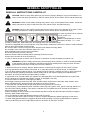
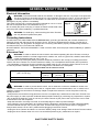
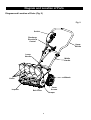
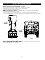
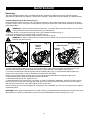
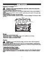
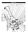
Electric Snow Thrower
60-3982-0
Owner's Manual
TOLL-FREE HELPLINE: 1 866 523-5218
IMPORTANT:
Read all safety rules and instructions carefully before using this product.
TABLE OF CONTENTS
Specifications . . . . . . . . . . . . . .. . . . . . . . . . . . . . . . . . . . . . . . . . . . . . . . . . . . . . . . . . . . . . . . . . . . . . . . . . . . . . . . . 2
General Safety Rules. . . . . . . . . . . . . . . . . . . . . . . . . . . . . . . . . . . . . . . . . . . . . . . . . . . . . . . . . . . . . . . . . . . . . . 3-6
Assembly Instructions . .. . . . . . . . . . . . . . . . . . . . . . . . . . . . . . . . . . . . . . . . . . . . . . . . . . . . . . . . . . . . . . . . . . . . . . . 7
Diagram and Location of Parts . . . . . . . . . . . . . . . . . . . . . . . . . . . . . . . . . . . . . . . . . . . . . . . . . . . . . . . . . . . . . . . . . 8
Operating Instructions . . . . . . . . . . . . . . . . . . . . . . . . . . . . . . . . . . . . . . . . . . . . . . . . . . . . . . . . . . . . . . . . . . . . . . 9-10
Maintenance . . . . . . . . . . . . . . . . . . . . . . . . . . . . . . . . . . . . . . . . . . . . . . . . . . . . . . . . . . . . . . . . . . . . . . . . . . . . 11-14
Troubleshooting. . . . . . . . . . . . . . . . . . . . . . . . . . . . . . . . . . . . . . . . . . . . . . . . . . . . . . . . . . . . . . . . . . . . . . . . . . . . 15
Warranty. . . . . . . . . . . . . . . . . . . . . . . . . . . . . . . . . . . . . . . . . . . . . . . . . . . . . . . . . . . . . . . . . . . . . . . . . . . . . . . . . . 16
Exploded View. . . . . . . . . . . . . . . . . . . . . . . . . . . . . . . . . . . . . . . . . . . . . . . . . . . . . . . . . . . . . . . . . . . . . . . . . . . . . 17
Parts list . . . . . . . . . . . . . . . . . . . . . . . . . . . . . . . . . . . . . . . . . . . . . . . . . . . . . . . . . . . . . . . . . . . . . . . . . . . . . . . . . . 18
SPECIFICATIONS
Motor:
120 V, 60 Hz, 10 A
Blade Speed:
Up to 2,600 RPM
Clearing width:
16” (40.6 cm)
Clearing depth:
6” (15.2 cm)
Discharge distance:
Up to 25' (7.6 m)
Impeller size:
14” (35.6 cm)
Wheels:
6” (15.2 cm)
Handle height:
33 to 38” (83.8 to 96.5 cm)
Weight:
24.5 lbs (11.1 kg)
2
GENERAL SAFETY RULES
READ ALL INSTRUCTIONS CAREFULLY!
CAUTION: Failure to obey safety warnings may result in property damage or injury to the operator or to
others. Follow the safety precautions in order to reduce the risk of fire, electric shock, and personal injury.
WARNING: Failure to obey safety warnings may result in injury to the operator and to others. Follow the
safety precautions in order to reduce the risk of fire, electric shock, and personal injury.
DANGER: Failure to obey safety warnings will result in serious injury to the operator or to others. Follow
the safety precautions in order to reduce the risk of fire, electric shock, and personal injury.
16" (40.6 cm) Electric Snow Thrower
120 V, 60 Hz, 10 A
60-3982-0
Made in China/Fabrique en Chine
Serial #/N* de serie: CTxx xxxxxx
In order to avoid injury, keep hands, feet, and clothing away from the rotating auger.
The motor is equipped with cut-out protection. If the motor stops, release the control bar in order to avoid accidental
start-up when the overload protector resets.
Do not use hands or feet to unclog the chute. Stop the motor before removing debris.
Do not walk in front of the Snow Thrower while it is in use.
Keep bystanders away from the area of operation.
Do not use the Snow Thrower in the rain.
Read the Owner’s Manual carefully before operating the Snow Thrower.
Use the Snow Thrower for snow removal only.
In order to reduce the risk of electric shock, use only an extension cord that is suitable for outdoor use.
WARNING: Follow the safety rules closely when using the Snow Thrower. In order to ensure the safety
of the operator and any bystanders, read these instructions carefully before using the Snow Thrower.
Keep these instructions in a safe place for future reference.
1. Read the instructions carefully. Become familiar with the controls and the proper use of the Snow Thrower.
2. Do not operate this Snow Thrower when tired, ill, or under the influence of alcohol, drugs, or medication.
3. Do not allow children under the age of 14 to operate this Snow Thrower. Children who are 14 years of age and
older must read the operating instructions and the safety rules in this manual carefully and understand the
thoroughly, and must be trained and supervised by a parent.
4. Inspect the Snow Thrower before use. Replace any damaged parts. Verify that all fasteners are in place and
secure. Replace any parts that are cracked, chipped, or damaged in any way.
5. Exercise caution in order to avoid slipping or falling.
6.Thoroughly inspect the area where the Snow Thrower will be used. Remove doormats, sleds, boards, wires,
debris, and other foreign objects that may be thrown by the Snow Thrower.
7. Verify that the rotor will be able to spin freely before turning the Snow Thrower on.
8. Dress properly. Wear adequate winter outerwear. Wear long heavy pants, boots, gloves, and long sleeves. Do
not wear loose clothing, jewellery, short pants, or sandals. Do not operate this Snow Thrower when barefoot.
Secure hair above shoulder level.
9.When operating the Snow Thrower, wear footwear that does not leak and that will improve footing on slippery
surfaces. Wear rubber-soled boots.
10. Do not attempt to make adjustments while the motor is running.
11. Allow the motor and the Snow Thrower to adjust to outdoor temperatures before beginning to clear snow.
12. Wear safety glasses/shields or goggles at all times while operating or performing adjustments or repairs in
order to protect the eyes from foreign objects that may be thrown by the Snow Thrower.
3
GENERAL SAFETY RULES
Electrical Information
WARNING: To avoid electrical hazards, fire hazards, or damage to the tool, use proper circuit protection.
The Snow Thrower is wired at the factory for 120 V operation. Connect to a 120 V, 15 A circuit and use a
15 A time delayed fuse or circuit breaker. To avoid shock or fire when the power cord is worn, cut, or
damaged in any way, replace it immediately.
1
This Snow Thrower has a 3-prong plug that is intended for use on a circuit
Fig. A
that has a receptacle like the one illustrated in Fig. A.
Do not modify the power cord plug. If it does not match the electrical outlet,
have the proper outlet installed by a qualified electrician.
2
1) 3-prong plug
WARNING: To avoid injury, when servicing the Snow Thrower,
2) Receptacle with grounding conductor
use only identical replacement parts.
Grounding Instructions
IN THE EVENT OF A MALFUNCTION OR BREAKDOWN, grounding provides the path of least resistance for
electrical current and reduces the risk of electric shock. This tool is equipped with an electric cord that has a
POLARIZED plug. The plug MUST be plugged into a matching outlet that is properly installed and grounded in
accordance with ALL local codes and ordinances.
DO NOT MODIFY THE PLUG PROVIDED. If it will not fit the outlet, have the proper outlet installed by a qualified
electrician.
Extension Cord
WARNING: In order to reduce the risk of electric shock when operating this Snow Thrower, use only a
CSA-listed extension cord that is approved for outdoor use, such as Type SJTW, 16AWG, and that has
a lower temperature rating of -40° F (-40° C).
• Ground Fault Circuit Interrupter (GFCI) protection should be provided on the circuit(s) or outlet(s) that will be
used for this Snow Thrower. For an extra measure of safety, use a receptacle that has built-in GFCI protection.
• The nameplate on the Snow Thrower indicates the voltage used. Do not connect the Snow Thrower to an AC
circuit that provides a different voltage from the voltage that is indicated on the nameplate.
Recommended size of extension cords
Amperage rating of the tool
(120 V circuit only)
More than
0
Not more than
12
Total length of the extension cord
25’
50’
100’
150’
(7.6 m)
(15.2 m)
(30.4 m)
(45.7 m)
Minimum Gauge for the extension cord (AWG)
16
16
14
14
[Use the same format for the table as found in the file entitled "Recommended size of extension cords".]
WARNING: In order to prevent electric shock, use an extension cord that is suitable for outdoor use.
• Inspect the extension cord and the power cord on a regular basis. Look for deterioration, cuts, or cracks in the
insulation. Inspect the connections for damage. Repair or replace the extension cord or the power cord if any
damage is found.
• Verify that the rotor and all moving parts have come to a complete stop, and disconnect the Snow Thrower from
the power supply in order to prevent accidental start-ups before cleaning or performing any inspections or repairs.
• Do not abuse the extension cord. Do not carry the Snow Thrower by the power cord or pull on the cord in order
to disconnect it from the receptacle.
• Keep the extension cord away from heat, oil, and sharp edges in order to prevent damage.
• If the extension cord is damaged in any manner while it is plugged in, disconnect it from the outlet immediately.
• Avoid accidental start-ups. Do not carry the Snow Thrower with a finger on the switch while it is plugged in.
Verify that the switch is in the "OFF" position before plugging in the Snow Thrower.
• Unplug the Snow Thrower and allow it to cool down before putting it into storage. Store the Snow Thrower indoors.
• Unplug the Snow Thrower when it is not in use and before performing any maintenance or repairs.
SAVE THESE SAFETY RULES
4
GENERAL SAFETY RULES
FOLLOW THESE RULES WHILE OPERATING THE SNOW THROWER
• Walk. Do not run.
• Verify that the Snow Thrower is not in contact with anything before turning it on.
• Stay away from the discharge opening at all times. Keep face, hands, and feet away from concealed, moving, or
rotating parts.
• Be attentive when using the Snow Thrower, and stay alert for holes in the terrain and other hidden hazards or
traffic.
• Do not use the Snow Thrower on a gravel or crushed rock surface. Use extreme caution when crossing
gravel/crushed rock drives, walks, or roads.
• Move up and down slopes when clearing snow. Do not go across a slope. Use caution when changing direction.
Do not use this Snow Thrower to clear snow from steep slopes.
• Do not attempt to use the Snow Thrower on a roof or on any steeply inclined slippery surface.
• Do not operate the Snow Thrower if the guards, plates, and other safety protective devices are not in place.
• Do not operate the Snow Thrower near glass enclosures, automobiles, trucks, window wells, drop-offs, etc.
without properly adjusting the angle of the snow discharge. Keep children and pets away from the work area.
• Do not force or overload the Snow Thrower. The Snow Thrower will perform better and safer when it is used at
the rate that it was designed to work at.
• Do not operate the Snow Thrower at high speeds on slippery surfaces. Look behind, and exercise caution when
backing up.
• Do not direct the discharge toward people, and do not allow anyone to move in front of the Snow Thrower while it
is in use.
• Wear safety glasses or goggles that meet ANSI Z87.1 standards, and wear ear/hearing protection when using
this Snow Thrower.
• Use the Snow Thrower in daylight or in good artificial light.
• Avoid accidental start-ups. Remain in the starting position when turning the Snow Thrower on. The operator and
the Snow Thrower must be in a stable position during start-up. See the section entitled Starting/Stopping Instructions.
• Use the proper tool. Only use this Snow Thrower for the purpose that it was designed for.
• Do not overreach. Always keep proper footing and balance.
• Hold the Snow Thrower with both hands while it is in use. Keep a firm grip on the handles or the grips.
• Keep hands, face, and feet away from all moving parts. Do not touch or try to stop the impeller while it is rotating.
• If the impeller does not rotate freely due to frozen ice, thaw the Snow Thrower thoroughly before attempting to
use it.
• Keep the impeller clear of debris.
• Do not attempt to clear the impeller while the motor running or while the Snow Thrower is plugged it. Turn the
motor off and unplug the Snow Thrower from the extension cord or the outlet.
• Keep clothing and body parts away from the rotor.
• Do not operate the motor at a faster speed than necessary. Do not run the motor at high speed while not clearing
snow.
• Stop the motor when snow clearing is delayed or when moving from one location to another.
• Unplug the Snow Thrower when it is being transported and when it is not in use.
• After striking a foreign object, turn the Snow Thrower off and unplug it, and then inspect it for damage. Repair
any damage before restarting and using the Snow Thrower.
• If the Snow Thrower starts to vibrate abnormally, stop the Snow Thrower immediately and attempt to determine
the cause. Vibration is generally an indication of danger.
• Stop the motor and unplug the Snow Thrower whenever the operator is not in the operating position, before
unclogging the impeller, and before making any repairs, adjustments, or inspections.
• Do not discharge snow onto public roads or near moving traffic.
• Allow the Snow Thrower to run for a few minutes after clearing snow in order to prevent moving parts from
freezing.
5
GENERAL SAFETY RULES
• Use only the manufacturer's original replacement parts and accessories for this Snow Thrower. The use of
unauthorized parts or accessories could lead to serious injury to the user or damage
the Snow Thrower, and will void the warranty.
• Do not use the Snow Thrower in the hand held position. Do not pick up the Snow Thrower while it is plugged and
running. The Snow Thrower is designed to travel along the ground.
• Verify that the Snow Thrower is secure while transporting.
• Store the Snow Thrower in a dry area, locked up or high enough to prevent unauthorized use or damage, and out
of the reach of children.
• Do not douse or squirt the unit with water or any other liquid. Keep handles dry, clean, and free of debris. Clean
the Snow Thrower after each use. See the section entitled Cleaning and Storage.
• If the labels on the Snow Thrower become defaced or start to lift off, contact the Toll-Free Helpline, at
1-866-523-5218.
• Keep these instructions in a safe place for future reference. Refer to them often, and use them to instruct other
users. Anyone who uses this Snow Thrower must read these instructions carefully.
• Maintain the Snow Thrower with care. Follow the instructions for lubricating and changing accessories.
6
ASSEMBLY
Assembling the Handle (Fig. 1)
1. Remove any packing material that may have been inserted between the upper and lower handles for shipping
purposes.
2. Align the holes (4) on the upper handle (1) with the holes on the middle handle (2). Insert the bolts (5), and use
the wing nuts (6) to tighten them.
3. Align the holes (7) on the middle handle (2) and the lower handle (3). Insert the bolts (5), and tighten them using
the wing nuts (6) provided.
Assembling the Discharge Directional Control (Fig. 1)
1. Align the holes (11) on the upper tubing (8) with the holes on the lower tubing (9). Insert the hitch pin (10).
Fig. 1
1
11
8
5
10
9
2
8
7
9
3
7
4
6
Diagram and Location of Parts
Diagram and Location of Parts (Fig. 2)
Fig. 2
Switch
Discharge
Directional
Control
Upper
Handle
Lower
Handle
Middle
Handle
Wheels
Vanes
Impeller
Cover
Screws
Belt Cover
Scraper
8
OPERATING INSTRUCTIONS
Starting the Snow Thrower
WARNING: Avoid accidental start-ups. Verify that the operator is in the starting position when using the
snow thrower. In order to avoid serious injury, the operator and unit must be in a stable position when
starting the Snow Thrower.
Using the Switch
This Snow Thrower is equipped with a special safety switch. In order to operate the switch, insert one finger into
the opening, and push the lever out so that it can be grasped along with the upper handle. Pull the lever back in
order to turn the Snow Thrower on, and hold it against the upper handle in order to keep it running. To turn the
Snow Thrower off, simply release the lever.
Caution: Do no attempt to override the operation of this safety switch.
Using the Snow Thrower
1. Start the Snow Thrower by following the Starting instructions. The depth and weight of the snow will determine
the forward speed.
2. Push the Snow Thrower forward so that it rides on the scraper.
3. Verify that the power cord is attached to the cord retainer and that it rests on the guide bar. The power cord
should trail to the side of the operator.
Using the cord retainer
Attach the outlet end of an extension cord to the plug
on the rear of the snow thrower.
Make a loop in the extension cord. From the right side,
pass the loop through the hole in the back of cord
retainer and place it around the hook.
PLUG
CORD
RETAINER
9
OPERATING INSTRUCTIONS
Adjusting the Direction of Discharge (Fig. 3-4)
Snow can be discharged to the left, straight ahead, or to the right of the operator.
Follow these instructions in order to change the direction of the discharge:
1. Release the switch bar in order to stop the rotor.
NOTE: The control stick can revolve 720°.
NOTE: From the center position, the discharge directional control turns approximately 360° in either direction
(clockwise or counter-clockwise). Do not force it.
2. Turn the discharge directional control clockwise 360°. The vanes will turn approximately 45° to the left .
3. Turn the discharge directional control counter-clockwise 360°. The vanes will turn approximately 45° to the right.
Discharge
Directional
Control
720
Discharge
Directional
Control
Fig. 4
Fig. 3
Tips for Best Snow Throwing Results
• For the most efficient snow throwing, keep the vanes parallel, and throw the snow in the direction of the wind.
• Slightly overlap each swath when clearing snow.
10
MAINTENANCE
Servicing
Servicing should be performed by a qualified technician. Replacement parts for this Snow Thrower must be
identical to the parts that they replace. If repairs are necessary, contact the Toll-Free Helpline, at 1-866-523-5218.
Inspecting/Replacing the Drive Belt (Fig. 5-7)
When servicing the Snow Thrower, use only the manufacturer's original replacement parts. Inspect the drive belt
for wear once per year or every 50 hours of operation, whichever comes first. If the drive belt needs to be replaced,
follow these steps.
WARNING: In order to avoid serious personal injury, turn off the Snow Thrower and allow it to cool down.
Unplug the Snow Thrower before performing any maintenance.
1. Remove the ten (10) screws from the belt cover using a phillips screwdriver (Fig. 5).
2. Remove the flange lock nut and the three (3) screws (Fig. 6) .
3. Remove the impeller pulley bracket using a washer or nut driver (Fig.6).
WARNING: In order to reduce the risk of electric shock, replace the cover before connecting the Snow
Thrower to a power source.
Fig. 5
Cover
Screws(10)
Impeller
Pulley
Bracket
Screws(3)
Fig. 6
Drive Pulley Fig. 7
Belt Tensioner
Impeller
Pulley
Flange Lock Nut
Belt
Washer
4. Pull the belt tensioner (idler arm) away from the drive pulley. Remove the damaged or broken belt from the
impeller pulley and the drive pulley inside the housing. Discard the belt in the proper manner (Fig. 7).
5. Loop the new belt around the drive pulley and the impeller pulley (Fig. 7). Pull the belt tensioner (idler arm)
away from the drive pulley in order to install the belt around the drive pulley.
NOTE: Verify that the washer is still in place on the impeller pulley shaft before reinstalling the belt cover.
6. Reinstall the impeller pulley bracket with the three (3) screws.
7. Reinstall the flange lock nut. Tighten the nut.
8. Reinstall the belt cover with the ten (10) screws. In order to facilitate the installation, position the narrow part of
the cover into the recess of the housing and install the two top screws, and then push the rest of the cover down
into the recess and over the rotor shaft. Tighten all ten (10) screws.
NOTE: If the flange lock nut is damaged, do not replace it with a standard nut. Use only the manufacturer's original
replacement parts.
WARNING: When fitting the belt back into the main housing, verify that the belt is positioned to the right of the Drive
Belt Retainer. If the belt is positioned to the left of the Drive Belt Retainer, serious damage may occur.
11
MAINTENANCE
Impellor replacement
1
2
3
spring
1. Remove the nut from the left hand side of
the impellor shaft.
4
2. Remove the 10 screws from the side cover.
5
3. Be sure not to lose the 2 springs.
6
spacer washer
washer and screw
4. Remove the washer and the screw.
7
5. Remove the nut from the impellor shaft.
Remove the 3 screws holding the pulley
support plate.
8
7. Remove the pulley and belt.
10
6. Remove the plate and the two spacer
washers.
9
8. Remove the impellor shaft nut from the
right hand side.
11
9. Withdraw the impellor shaft from the left
hand side.
12
spacer washer
10. Withdraw the old/damaged impellor.
Be sure to keep the 2 spacer washers
from the right hand side of the impellor.
11. Insert the impellor shaft in the new
impellor and place the 2 washers on the
right hand side.
12
12. Place the impellor and shaft back into the
front scoop.
MAINTENANCE
Impellor replacement
13
14
13. Place the pulley back onto the impellor
shaft.
16
15
14. Be sure to route the belt correctly, as
shown.
17
15. Replace the 2 spacer washers on the
impellor shaft.
18
washer and screw
impellor shaft washer and nut
16. Replace the pulley support plate and the
3 retaining screws.
19
17. Replace and tighten the impellor shaft
washer and nut.
20
18. Replace the washer and the screw.
21
spring
19. Place the lower spring into position and
slide the side cover up using slight
pressure to hold the spring in place.
20. Replace and tighten the remaining screws
and the nut and washer.
13
21. Re-install the impellor shaft nut and
washer on the right hand side, and
tighten.
(Fig. 8)
(Fig. 8)
Fig. 8
14
TROUBLESHOOTING
Problem
Possible Causes
Solutions
Then handle is not in
position.
The carriage bolts are not properly
seated
Adjust the height of the handle, and verify
that the carriage bolts are properly seated.
Tighten the knobs.
The Snow Thrower
does not start.
The Snow Thrower is unplugged.
Verify that the Snow Thrower is plugged into
an electrical outlet.
Press and hold the lock-out button, and then
lift and hold the trigger switch (see the
section entitled Starting the Snow Thrower).
The motor is on, but
the rotor does not turn.
The belt is damaged.
The belt is damaged.
Replace the belt (see the section entitled
Inspecting/Replacing the Drive Belt).
The Snow Thrower
leaves a thin layer of
snow behind.
The scraper is worn
Replace the scraper (see the section entitled
Replacing the Scraper).
The lock-out button or trigger switch
were not used properly.
15
WARRANTY
For TWO YEARS from the date of purchase within Canada, YARDWORKS CANADA will, at its option, repair or
replace for the original purchaser, free or charge, any part or parts found to be defective in material or workmanship.
This warranty does not cover:
1. Any part which has become inoperative due to misuse, commercial use, abuse, neglect, accident, improper
maintenance or alteration; or
2. The unit, if it has not been operated and/or maintained in accordance with the owner's manual;or
3.Normal wear, except as noted below;
4.Routine maintenance items such as impeller, blade sharpening;
5.Normal deterioration of the exterior finish due to use or exposure.
Full One Hundred Twenty Days Warranty on Normal Wear Parts: Normal wear parts are defined as blade adaptors,
blades, grass bags and tires. These parts are warranted to the original purchaser to be free from defects in material
and workmanship for a period of one hundred twenty (120) days from the date of retail purchase.
How to Obtain Service: Warranty service is available, with proof of purchase, through your local authorized service
dealer or distributor. If you do not know the dealer or distributor in your area, please call toll free 1 866 523-5218.
The factory will not accept the return of a complete unit unless prior written permission has been extended by
YARDWORKS CANADA.
Transportation Charges: Transportation charges for the movement of any power equipment unit or attachment are
the responsibility of the purchaser. The purchaser must pay transportation charges for any part submitted for
replacement under this warranty unless such return is requested in writing by YARDWORKS CANADA.
Other Warranties: All other warranties, express or implied, including any implied warranty of merchantability is limited
in its duration to that set forth in this express limited warranty. The provisions as set forth in this warranty provide the
sole and exclusive remedy of YARDWORKS CANADA obligations arising from the sale of its products.
YARDWORKS CANADA will not be liable for incidental or consequential loss or damage.
16
PARTS LIST
17
PARTS LIST
No
1
2
3
4
5
6
7
8
9
10
11
12
13
14
15
16
17
18
19
20
21
22
23
24
25
26
27
28
29
30
31
32
33
34
35
36
Model num.
3118099
3220436
3410835-4
3330299-3
3330399-3
3290135
3220199
3290799
3290699
3411799-1
3411799C
3330398
3220299
Description
Upper handle assembly
Screw
Knob
Middle handle
Down handle
Clip pin
Screw
Shrapnel
Gasket
Left wheel assy.
Wheel cover
Motor mounting bar
Screw
Qty
1
4
4
1
1
2
4
4
4
1
2
1
2
3220598
3118199
3220299
3331099
3220999
3411535
3390198
3290198
3111198
3390298
3330999
3220298
3290499
3220998
3220236
3330198
3220898
3111298A
3410399
3111399A
3290173
3220110
3411399A
Screw
Motor assembly
Screw
Left inside steel support
Screw
Press cord board
Tension spring
Belt
Tension wheel assembly
Spring
Left cover
Screw
Gasket
Nut
Nut
Impeller pulley bracket
Gasket
Impeller pulley assembly
Down cover
Impellor assembly
Gasket
Screw
Scraper
2
1
4
1
2
1
1
1
1
2
1
10
3
2
1
1
5
1
1
1
2
2
1
18
No
37
38
39
40
41
42
43
44
45
46
47
48
49
50
51
52
53
54
55
56
57
58
59
60
61
62
63
64
65
66
67
68
69
70
71
Model num.
3225599
3320299-A
3331399
3221099
Description
Screw
Impeller shaft
Auxiliary board
Screw
Qty
5
1
1
7
3410999A
Vanes
4
3331199
Right inside steel support
1
3411099
Link bar
1
3410799
Small gear
1
3290299
Gasket
8
3290699
Gasket
6
3410899A
Big gear
1
3290999
Ball
1
3340199
Spring
1
3331299
Spring press board
1
3410699
Locking knob
1
3410199
Upper cover
1
3220298
Screw
6
3410299
Transparent panel
1
3420299
Sealing ring
1
3420102
Strain relief
1
3330799
Upper rocker
1
3411799-2
Right wheel assy.
1
Gasket
32262198
2
Loop
1
3320640
31100199
Pigtail cable
1
1
3330499
Screw
3420199
Rubber washer
1
Gasket
3290299
1
3290599
Nut
1
Rear rocker
3330599-1
1
3410499-1
Handle
1
Gasket
1
3330211
Loop
32901251
1
2
3411135
Power cable clip
31100199
1
Switch box