1
MANUAL NO. 993-041990-002
OWNERS and
SERVICE MANUAL
for
nnaoq
MINITMOOG/
SATELLITE
Minitmoog
Model 300A
Satellite
Model 5330
Introduction
The owners portion of this manual, pages 1 through 11, provides introductory material to
familiarize the owner with the features, specifications and initial set-up of the Minitmoog
Synthesizer, Model 3Q0A, and the Satellite Synthesizer, Model 5330.
The technical portion of this manual, pages 12 through 57, provides servicing,, replacement
parts list and illustrations to enable a qualified technician to service and maintain the
Minitmoog and Satellite Synthesizers.
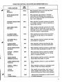
Index
SATELLITE SYNTHESIZER
MINITMOOG SYNTHESIZER
PAGE
CONTENTS
Controls
Quick-Set Voice Tabs
2
Modulation, Oscillation and
Touch Controls
Slide Control Panel
CONTENTS
PAGE
Controls
5
Quick-Set Voice Tabs
6
Modulation
8
Slide Control Panel
9
3
4
Accessories and Connections
10
Accessories and Connections
10
Care of Your Synthesizer
11
Care of Your Synthesizer
11
Technical Sections
12
Technical Sections
12
THESE DRAWINGS AND SPECIFICATIONS ARE THE PROPERTY OF
MOOG MUSIC INC. AND SHALL NOT BE REPRODUCED OR COPIED IN
WHOLE OR IN PART AS THE BASIS FOR MANUFACTURE OR SALE OF
THE ITEMS.
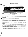
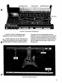
Minitmoog Controls
SLIDE
CONTROLS
PANEL
MODULATION
CONTROLS
GLIDE
CONTROL
SYNC, GLIDE
POWER
OFF-ON
SWITCH
INDICATOR
LIGHT
SOLO
KEYBOARD
VOLUME
CONTROL
SUSTAIN TABS
FILTER
CONTROLS
TOUCH
SENSE
QUICK-SET VOICING
TABS
MODULATION
TABS
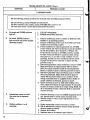
Before proceeding with Operation and Adjustment of your unit, please refer to page 10 for Connection Instructions.
LEVEL ADJUST
M u
.
e
„
This rotary control (located on the back of the unit) sets the overall output level, or volume, of the unit. Smaller
changes in volume may be made with the VOLUME control on the Slide Control Panel.
This rotary control (located on the back of the unit) provides a range of tuning which extends more than one-half
octave. This flexibility can be used to tune your MOOG MINITMOOG to other instruments, transpose to different keys,
or even provide a glissando effect.
POWER AND INDICATOR LIGHT
.
u
.
An ON-OFF power switch is conveniently located on the front panel, with a red light which indicates when the
power is ON.
OCTAVES
t
With neither tab depressed, your MOOG MINITMOOG will play in its highest pitch level. Depress tab
.
. t
1 , and what
ever you play on the keyboard will be one octave lower. Raise tab "1" and depress tab "2", and the keyboard pitch
level is lowered another octave. Depress both tabs and the pitch level is lowered still a third octave. Because of the
electronic tailoring of the sounds to the requirements of each pitch level, you will find that the effectiveness of every
sound seems to change magically as you change from octave to octave. Try all sound effects in all four pitch levels.
SUSTAIN
.
. .
This "Quick-Set" tab allows the sound of a note to "linger" after the key is released. It provides interesting variations
to the special voice settings described in this Manual.
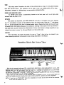
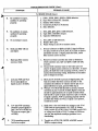
Minitmoog Quick-Set Voice Tabs
GUITAR-1
VIOLIN
TAURUS
With the unit connected and power ON, a sound can be heard when a note on the keyboard is struck, even though no
voices are selected and all slide controls are set at "0" (except for the VOLUME control). The controls described herein
will add and subtract from that sound in a multitude of combinations available for your exploration - shape it, change its
attack and release, raise it, or lower it. We suggest that you play a phrase or two with each of the twelve "QUICK-SET"
VOICE TABS conveniently located on the front of the unit. Try each with all the slide controls set at "0" (except for
VOLUME).
Exact setting of slide controls for any particular effect will depend, not only on your musical taste, but also on your
complete electronic reproduction system including amplifiers, speakers and other components.
NOTE: If more than one "QUICK-SET" Voice Tab is depressed at the same time the sound will be that controlled
by the Voice Tab farthest to the left.
MUTE
This voice is a new version of the wah-wah effect.
The sound approximates a double-acting wah-wah, or
"ooo-wah-ooo." It starts with an emphasis on the "lows",
moves to the "highs" and returns. Each time a key is
depressed the "ooo-wah-ooo" sound is produced. Try it
in each octave.
TRUMPET
The sounds of a trumpet, trombone, or tuba can be
approximated by selecting this tab, and varying it with
other controls. Characteristic of this voice (and some of
the other "Quick-Set" voices) is a built-in timbre change
which is faster in the upper octaves and is automatically
slower in the lower octaves • much as the attack of a tuba
differs from that of a trumpet. This attention to the
authentic details of the attack in different octaves is a
unique feature of the Minitmoog. Try it in each octave
setting.
OBOE
This voice provides a sound similar to that of a double
reed. In the top octave the sound is oboe-like. In the
lower octaves, the sound of a bassoon is approximated.
You will note a slight timbre change in the onset of the
tone and a slow attack.
CLARINET
The hollow reed sound and the soft attack of the
traditional clarinet and bass clarinet are characteristic of
this voice
-
an excellent voice in all octave registers.
SAX
This full bodied reed sound is unique to the Minitmoog.
It combines some of the qualities of a double reed wind
instrument with those of a pipe organ with a little sax
ophone added. In the lowest registers, it is an excellent
reproduction of the sound- of the sarrusophone, a wind
instrument popular in bands of the early 1900's.
AIRES
TAURUS
This voice approximates that of a saxophone. With
adjustment
of other controls you will be able to vary the
aa
und through the characteristics of alto and tenor, barine, and bass sounds of the Taurus Synthesizer.
we
Banjo type sounds are provided with the hollow
sound characteristic of this voice. In the lower registers
it can simulate the plucked sound of the string bass, or
bass violin.
VIOLIN
This gentle voice with its slow attack can be made to
simulate violin, viola, cello, and even some of the sounds
of the bass violin.
GUITAR-1
This sound is quite percussive with a lingering decay.
It is most useful for creating guitar-like or harpsichordtype effects, including that of a folk guitar.
In the upper octaves a fine bell sound is provided by
this voice. In the lower octaves, the huge sound of a
large carillon can be reproduced.
LUNAR
This
PIANO
In the upper registers this voice is that of an electronic
piano.
GUITAR -2
In the lower registers it provides an interesting
sound similar to that of an electric bass guitar.
versatile
voice
of the
Moog sounds.
ments,
a
wide
perhaps
is
most
characteristic
It provides, in its various adjust
variety
of
timbre
changes with which
you can produce many popular electronic "Moog" sound
effects. It is most effective when used with SUSTAIN.
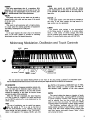
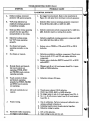
Minitmoog Modulation, Oscillation and Touch Controls
RATE
DEPTH
TREMULANT
•B" PITCH'
A/BMIX
TOUCH
SENSE
VIBRATO
FILTER
MODULATION
The two function tabs labeled MODULATION on the front of the unit provide a selection of modulation types.
The two MODULATION slide controls on the slide control panel adjust the RATE and DEPTH of modulation.
VIB (VIBRATO)
This tab provides a frequency-modulation vibrato simi
lar to the type used in electronic organs. However, the
wide range of effects offered by the two slide controls
extends the capability of this effect far beyond vibrato
and into the realm of the synthesizer.
When the VIB tab is depressed, the basic frequency
of a note is varied (or "wiggled") to a degree determined
by the DEPTH control and at a rate determined by the
RATE control.
RATE
The rate of modulation may be varied from approxately one second at "0" to a rate so fast that at
10" the sound becomes a buzz. However, even at ex
treme settings, the basic character of the "QUICK-SET"
voices is still apparent. For instance, MUTE, with VIB
plus RATE at 10 becomes a BUZZ-WAH type of effect.
With slower settings it is easy to obtain the effect of
trills between notes, regardless of the voice selected.
DEPTH
This control adjusts the degree or intensity of modu
lation. For vibrato (VIB), increasing DEPTH corresponds
to greater frequency variation. This frequency variation
may
be adjusted from less than one-half step (on the
scale) to more than one octave. For tremulant (TREM),
increasing DEPTH corresponds to greater timbre variation.
This flexibility, combined with the RATE control,
makes possible synthesis of such effects as "out of tune"
strings, huge bells whose clanging sounds interfere with
each other, quarter tone scales, trumpet "shake" effects,
and a myriad of others.
MOD
TREM (TREMULANT)
This tab provides modulation of the harmonic content
of the tone. The harmonic content, or timbre, is varied at
a rate determined by the RATE control and with an
intensity determined by the DEPTH control.
This tab allows either vibrato or tremolo to be added
to the tone as the pressure on the keys is increased. The
NOTE:
only if the MODULATION VIB or MODULATION TREM
VIB and TREM can be used together.
DEPTH slide control in this mode acts as a touch sensitiv
ity control and the MODULATION RATE slide control
sets the speed of the effect. This tab switch has an effect
Q
tab switch is also depressed.
SYNC
This tab is only active when other SYNC tab switch is
also down. Raises pitch of B tone osciliator as a key is
depressed harder producing a phasing effect.
PITCH
This tab bends pitch of both A and B tone oscillators
up to an interval of at least seven semitones when a key
is depressed harder.
TOUCH SENSE
This control regulates the range of expressive effects
when additional pressure is exerted on the keys for
SYNC, PITCH and FILTER (brightness) modes.
"B" PITCH
This control varies pitch ol B tone producing oscillator
over a two octave range.
FILTER
This tab adds familiar Moog "wah" to most voices
when pressure on the keys is increased. This effect adds
directly to the effect produced by the FILTER BRIGHT
NESS slide control.
A/B MIX
Controls mixing of A and B tone source oscillator
outputs. A only or B only occur at the CCW and CW
extremes of rotation, respectively.
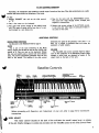
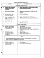
Minitmoog Slide Control Panel
GLIDE
VOLUME
BRIGHTNESS
DECAY
ATTACK
FILTER CONTROLS
u
. .
Once a "Quick-Set" tab voice selection is made, further refinement and adjustment of that voice may be made oy
using the three slide controls labeled FILTER.
ATTACK
This controls the speed of the timbre change associated
with the onset of the voice, and/or the timbre change
associated with the release of that voice. The wide range
of this control can provide both slow settings (useful
for simulation of bass violin or tuba effects) and fast
timbre change settings (which can provide wild chirping
effects).
DECAY
This acts as a brightness control, but it has such a
wide range that it can have major effect on the basic
sound itself. Your choice may lie anywhere between
adding in all of the high harmonics you wish, or elim
inating them.
BRIGHTNESS
This control adds a resonance frequency area to the
spectrum of the tone. At "0", spectrum of the "QuickSet" sound is unchanged. As the control is pushed forward,
the intensity of the sound within a pre-selected resonance
area is increased. At maximum, there is a well defined
narrow sharp peak in the spectrum of the tone.
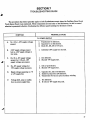
FILTER CONTROLS SUMMARY
Remember, the "Quick-Set" tabs establish an overall range of sound and the three Filter slide controls give you a wide
selection and control within the limitations of that range.
Try this:
1. Depress TRUMPET tab, and set the slide controls
at "0".
4. Now do the same with the BRIGHTNESS control.
The sound will range through cornet, trumpet, and
flugelhorn characteristics.
2. Play a few notes on the keyboard.
3. Play again with various settings of the DECAY slide
pot. The range of sound will be from that of a very
dull trumpet to a very brassy one.
5. Repeat with various settings of the ATTACK control.
It will show the wide range of contoured timbers in
the onset of the tones.
ADDITIONAL CONTROLS
determines the speed of the glissando, {10 is slow - 1 is
fast). Try a melody of detached notes and notice the
MODULATION CONTROLS
See discussion under MODULATION on page 3.
GLIDE
succession of glide attacks.
This is one of the most interesting of the Moog
effects. Depress the GLIDE tab and set the GLIDE slide
control at 6. Play any note on the keyboard. Release
this note and quickly play a second note some distance
away. The sound automatically glissandos from the first
note to the second. The setting of the slide control
VOLUME
The VOLUME slide control provides finger-tip adjust
ment of fine gradations of the Minitmoog output. Major
changes in sound level are obtained by means of the
rotary knob on the back of the unit.
Satellite Controls
SUOE
CONTROLS
PANEL
GLIDE
CONTROL
VOLUME
CONTROL
LEVEL & TUNE CONTROLS
(LOCATED ON REAR PANEL)
ACCESSORY & OUTPUT
CONNECTIONS
(LOCATED ON REAR PANEL)
SOLO
KEYBOARD
GLIDE, SUSTAIN
TABS
Before proceeding with Operation and Adjustment of your unit,refer to page 10 for Connection
Instructions.
LEVEL ADJUST
This rotary control (located on the back of the uniOsets the overall output level, or volume,
of the unit. Smaller changes in volume may be made with the VOLUME control on the Slide Control Panel.
\
TUNE
This rotary control (located on the back of the unit) provides a range of tuning which extends
more than one-half octave.
This flexibility can be used to tune your MOOG SATELLITE to other
instruments, transpose to different keys, or even provide a glissando effect.
POWER AND INDICATOR LIGHT
An ON-OFF power switch is conveniently located on the front panel, with a red light which
indicates when the power is ON.
OCTAVES
With neither tab depressed, your MOOG SATELLITE will play in its highest pitch level. Depress
tab "V, and whatever you play on the keyboard will be one octave lower. Raise tab "1" and depress
tab "2", and the keyboard pitch level is lowered another octave. Depress both tabs and the pitch level
is lowered still a third octave. Because of the electronic tailoring of the sounds to the requirements of
each pitch level, you will find that the effectiveness of every sound seems to change magically as you
change from octave to octave. Try all sound effects in all four pitch levels.
SUSTAIN
This "Quick-Set" tab allows the sound of a note to "linger" after the key is released. It pro
vides interesting variations to the special voice settings described in this Manual.
Satellite Quick-Set Voice Tabs
BRASS VOICES'
•MUTE
• OPEN
REED VOICES
•THIN
•HOLLOW
• FULL
• BRIGHT
STRING VOICES
•BOW
BELL
• PLUCK
•STRIKE
• PICK
With the unit connected and power ON, a sound can be heard when a note on the keyboard is stiuck. even
though no voices are selected and all slide controls are set at "0" (except for the VOLUME control i. The controls
described herein will add and subtract from that sound in a multitude of combinations <iv.ii Lib k* tor your
exploration - shape it, change its attack and release, raise it, or lower it. We suggest Unit you play a phrase or
two with each of the twelve "QUICK-SET" VOICE TABS conveniently located on the front ol ihc unit. Try each
with all the slide controls set at "0" (except for VOLUME).
Exact setting of slide controls for any particular effect will depend, not only on your musical taste, but
also on your complete electronic reproduction system including amplifiers, speakers and other components.
NOTE: If more than one "QUICK-SET" Voice Tab is depressed at the same time the sound will be that controlled
by the Voice Tab farthest to the left.
MUTE BRASS
BRIGHT REED
"lows", moves to the "highs" and returns. Each time a
With adjustment of other controls you will be able
to vary the sound through the characteristics of
alto and tenor, baritone, and even bass saxophone.
This voice is a new version of the wah-wah effect.
The sound approximates a double-acting
wah-wah,
.or "ooowah-ooo." It starts with an emphasis on the
key is depressed the "ooo-wah-ooo" sound is pro
duced. Try it in each octave.
OPEN BRASS
The sounds of a trumpet, trombone, or tuba can be
approximated by selecting this tab, and varying it
with other controls. Characteristic of this voice (and
some of the other "Quick-Set" voices) is a built-in
timbre change which is faster in the upper octaves
and is automatically slower in the lower octaves —
much as the attack of a tuba differs from that of a
trumpet. This attention to the authentic details of the
attack in different octaves is a unique feature of the
Satellite. Try it in each octave setting.
THIN REED
This voice provides a sound similar to that of a
double reed. In the top octave the sound is oboe-like.
In the lower octaves, the sound of a bassoon is
approximated. You will note a slight timbre change
in the onset of the tone and a slow attack.
HOLLOW REED
The hollow reed sound and the soft attack of the
raditional clarinet and bass clarinet are character
istic of this voice - an excellent voice in all octave
registers.
This
voice
approximates
that
of
a
saxophone.
BOW STRING
This gentle voice with its slow attack can be
made to simulate violin, viola, cello, and even some
of the sounds of the bass violin.
PLUCK STRING
This sound is quite percussive with a lingering
decay. It is most useful for creating guitar-like or
harpsichord-type effects, including that of a folk
guitar.
STRIKE STRING
In the upper registers this voice is that of an
electronic piano. In the lower registers it provides
an interesting sound similar to that of an electric
bass guitar.
PICK STRING
Banjo type sounds are provided with the hollow
sound characteristic of this voice. In the lower
registers it can simulate the plucked sound of the
string bass, or bass violin.
BELL
In the upper octaves a fine bell sound is provided
by this voice. In the lower octaves, the huge sound
of a large carillon can be reproduced.
FULL REED
This full bodied reed sound is unique to the
Satellite. It combines some of the qualities of a
double reed wind instrument with those of a pipe
organ with a little saxophone added. In the lowest
registers, it is an excellent reproduction of the
sound of the sarrusophone, a wind instrument popular
in bands of the early 1900's.
LUNAR
This versatile voice perhaps is most characteris
tic of the Moog sounds. It provides, in its various
adjustments, a wide variety of timbre changes with
which you can produce many popular electronic
"Moog" sound effects. It is most effective when used
with SUSTAIN.
Satellite Modulation
Tfrf
RATE—'
DEPTH
REPEAT-*
' I
UTREMULANT
VIBRATO
The four function tabs labeled MODULATION on the front of the unit provide a selection of modulation
types. The two MODULATION slide controls on the slide control panel adjust the RATE and DEPTH of modulation.
VIB (VIBRATO)
This tab provides a frequency-modulation vibrato
REP (REPEAT)
The repeat tab affects only those "QUICK - SET"
similar to the type used in electronic organs. However,
the wide range of effects offered by the two slide
controls extends the capability of this effect far
voices which have built-in timbre changes. The timbre
beyond vibrato and into the realm of the synthesizer.
When the VIB tab is depressed, the basic frequency
RATE slide control. This
depressing MUTE BRASS,
of a note is varied (or "wiggled") to a degree deter
and setting RATE at 0. Play a sustained tone, then
slowly move the slide control to 10 and return, while
mined by the DEPTH control and at a rate determined
by the RATE control.
RATE
The rate of modulation may be varied from approx
imately one second at "0" to a rate so fast that at
"10" the sound becomes a buzz. However, even at
extreme settings, the basic character of the "QUICK
SET" voices is still apparent. For instance, MUTE
BRASS, with VIB plus RATE at 10 becomes a BUZZ-WAH
type of effect. With slower settings it is easy to
obtain the effect of trills between notes, regardless of
the voice selected.
DEPTH
This control adjusts the degree or intensity of
modulation. For vibrato (VIB), increasing DEPTH
corresponds to greater frequency variation. This
frequency variation may be adjusted from less than
one-half step (on the scale) to more than one octave.
For tremulant (TREM), increasing DEPTH corresponds
to greater timbre variation.
This flexibility, combined with the RATE control,
makes possible synthesis of such effects as "out of
tune" strings, huge bells whose clanging sounds
interfere with each other, quarter tone scales, trumpet
"shake" effects, and a myriad of others.
TREM (TREMULANT)
This tab provides modulation of the harmonic
content of the tone. The harmonic content, or timbre,
is varied at a rate determined by the RATE control
and with an intensity determined by the DEPTH control.
NOTE: VIB and TREM can be used together.
8
change associated with a specific voice will be repeated
over and over again at a speed controlled by the
is easily demonstrated by
REP, OCTAVE 1 and 2,
sustaining the tone.
NOTE: The DEPTH slide control has no effect on the
REP function.
\\s\rui
This control provides a most versatile tool in
achieving the distinctive sounds associated with
the MOOG synthesizer. It affects the type of modu
lation obtained by two of the other MODULATION
functions, VIBRATO and TREMULANT.
When this tab is in the up position,
VIB and TREM are with a square-wave putioui. The
variation of frequency (VIB), or variation ol timbres
(TREM), will be very abrupt and choppy. with discon
tinuities. With VIB, for instance, a defmiiivn variation
in frequency can be obtained, like a trill
When
+1/1 rut
is depressed, a sine wave type
of modulation is obtained which provides a smooth
variation of timbre or frequency - almost a glissando.
The difference between the two effects is easily
discernible in the following ciniructunstically M00G-
type settings. Depress
ii/irut
. MUTE BRASS,
OCTAVE 2, VIB, set RATE at 3. and DEPTH at 6.
Depress any key on the keyboard and listen to the
smooth variation in frequency as you keep your
finger on the key. Then raise the tab marked ♦b^rut
and observe the abrupt variation in frequency. Repeat
the above steps with TREM instead of VIB, and then
combine the two.
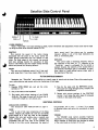
Satellite Slide Control Panel
L EMPHASIS
FILTER CONTROLS
Once a "Quick-Set" tab voice selection is made, further refinement and adjustment of that voice may be made
by using the three slide controls labeled FILTER.
CONTOUR
This
controls
the
speed
of
the
timbre
change
associated with the onset of the voice, and/or the
timbre change associated with the release of that
voice. The wide range of this control can provide
both slow settings (useful for simulation of bass
violin or tuba effects) and fast timbre change settings
(which can provide wild chirping effects).
COLOR
a
This acts as a brightness control, but it has such
wide range that it can have major effect on the
basic sound itself. Your choice may lie anywhere
between adding in a|l .of the high harmonics you
wish, or eliminating them.
EMPHASIS
This control adds a resonance frequency area to
the spectrum of the tone. At "0", spectrum of the
"Quick-Set" sound is unchanged. As the control is
pushed forward, the intensity of the sound within a
pre-selected resonance area is increased. At maxi
mum, there is a well defined narrow sharp peak in
the spectrum of the tone.
FILTER CONTROLS SUMMARY
Remember, the "Quick-Set" tabs establish an overall range of sound and the three Filter slide controls give
you a wide selection and control within the limitations of that range.
Try this:
1. Depress
OPEN
BRASS
tab,
and
set
the
slide
controls at "0".
4. Now do the same with the EMPHASIS control.
The sound will range through cornet, trumpet, and
flugelhorn characteristics.
2.
Play a few notes on the keyboard.
3.
Play again with various settings of the COLOR
slide pot. The range of sound will be from that of
a very dull trumpet to a very brassy one.
5.
Repeat with various settings of. the CONTOUR
control. It will show the wide range of contoured
timbres in the onset of the tones.
ADDITIONAL CONTROLS
MODULATION CONTROLS
See discussion under MODULATION on
page 8.
GLIDE
This is one of the most interesting of the Moog
effects. Depress the GLIDE tab and set the GLIDE
slide control at 6. Play any note on the keyboard.
Release this note and quickly play a second note
some
distance
away.
The
sound
automatically
glissandos from the first note to the second. The
setting of the slide control determines the speed of
the glissando, (10 is slow - 1 is fast). Try a melody
of detached notes and notice the succession of glide
attacks.
VOLUME
The VOLUME slide control provides finger-tip
adjustment of fine gradations of the Satellite output.
Major changes in sound level are obtained by means
of the rotary knob on the back of the unit.
9
Accessory and Connections
For operation, the Synthesizer unit should be placed on a horizontal surface in a location which will not interfere
with its operation.
NOTE: Avoid placement in close proximity to electronic circuitry, as on the top of some electronic organs, because
excessive hum may result.
LO-LEVEL OUTPUT 130 millivolts RMS), Phone Jack
designed for use with Guitar Amplifier, P.A. Systems, etc.
HI-LEVEL OUTPUT (1 volt RMS), RCA Phono Jack
designed for use with Electronic Organs. ("Y" Adapter
and Accessory extension cable are included with your unit).
REAR PANEL
ORGAN AMPLIFIER
ACCESSORY
EXTENSION
CABLE
RIGHT OR MAIN
RIGHT OR MAIN
CHANNEL INPUT
PLUG
CHANNEL INPUT
JACK
.FROM ORGAN
Connection Instructions
SINGLE CHANNEL ORGANS (MONAURAL)
Disconnect the RCA Phono plug from Amplifier Input Jack and insert the "Y" Adapter plug into the Amplifier inpui
Jack. Connect Accessory extension cable plug into "Y" Adapter socket and insert the plug on the other end ol the
extension cable into the HI-LEVEL OUTPUT jack on your Synthesizer unit. Connect the organ plug (previouslv removed)
into the other "Y" Adapter socket.
DUAL CHANNEL ORGANS (STEREO)
Disconnect the RCA Phono plug from the Right of Main Channel Amplifier Input Jack and insert "Y" AOaptoc plug
into Right or Main Channel Input Jack. Connect the Accessory extension cable plug into the "Y" Adapter socket and
insert the plug on the other end of the extension cable into HI-LEVEL OUTPUT jack on your Synthesiser unit. Connect
the Right or Main Channel plug (previously removed) into the other "Y" Adapter socket.
NOTE:
Do not connect the Synthesizer into Leslie or Left Channel Input.
FILTER CONTROL INPUT
This jack is provided for the control of the Timbre with a Moog Pedal controller.
ACCESSORY SOCKET
, x
Permits the attachment of a Foot Pedal to control several Synthesizer features. (Consult your dealer for availability
of Moog Accessories).
10
Care of Your Synthesizers
Your MOOG Synthesizer is carefully designed to give you maximum pleasure and
satisfaction with a minimum of care. Following these tips on the care of your Synthesizer
will help keep it "showroom new."
■ LOCATION
As with any electronic instrument, avoid placement in direct or prolonged sunlight. Normal variation of temper
ature will not affect the tuning or electronic circuitry of the synthesizer. Storage location should be chosen to avoid
placement in front of hot air registers, or beside an outside doorway in winter, as these elements may affect the
finish of the cabinet.
• CABINET
Quality hardwoods are used in your MOOG Synthesizer. Therefore, a minimum amount of care wijl insure you
of having a piece of furniture that will retain its beauty. An occasional dusting with a soft, dry cloth should remove
both fingerprints and dulling film. To clean the keys a soft cloth dampened in a mild soap solution should remove
even the most persistent stains. Under no circumstances should solvents or cleaning fluids be used to clean keys
or cabinet.
■ POWER REQUIREMENTS
This instrument must be operated from a standard 120 VAC 60Hz power outlet. Normal line voltage variation
will not affect its operation. Power requirements of this unit are very low. All solid state circuits are operated at a
very low voltage and component life is therefore extended.
■ SAFETY
Your MOOG Synthesizer has been designed for maximum safety in its operation and trouble free performance.
However, repair or service of electronic products should be done by qualified personnel familiar with the hazards
relating to electricity and electronic circuitry. The risk of repair or service must not be assumed by the customer.
Your dealer will provide a competent, experienced service technician for that purpose. Please contact your dealer, if
your unit needs repair or service.
■ CONCLUSION
And now as you play .... Let us offer you our best wishes for a happy and rewarding experience with your MOOG
Synthesizer. We know it will bring you great pleasure and creative satisfaction.
11
TECHNICAL
SERVICE SECTION
for
MINITMOOG/
SATELLTE
Minitmoog
Model 300A
Satellite
Model 5330
12
CONTENTS
SECTION
1
INTRODUCTION
2
CIRCUIT DESCRIPTION
2.1 GENERAL
2.2 POWER SUPPLY
2.3 KEYBOARD CIRCUIT
2.4
2.5
2.6
2.7
2.8
2.9
2.10
2.11
3
PAGE
15
15
15
15
16
OSCILLATOR
BAND PASS FILTER
LOW PASS FILTER
VOLTAGE CONTROLLED AMPLIFIER
AMPLITUDE CONTOUR GENERATOR
FILTER CONTOUR GENERATOR
MODULATION OSCILLATOR
TOUCH SENSOR
18
20
20
20
21
22
22
22
•
DISASSEMBLY, VISUAL INSPECTION AND REASSEMBLY
4
3.1
3.2
3.3
DISASSEMBLY
VISUAL INSPECTION
PRINTED CIRCUIT BOARD REMOVAL.
3.4
REASSEMBLY
TUNING AND CALIBRATION PROCEDURES
4.1
4.2
4.3
GENERAL
OSCILLATOR TUNING
VOICE CALIBRATION
23
23
23
23
,
25
25
25
25
29
5
OPERATING CONTROLS, INDICATORS AND CONNECTORS
31
6
KEYBOARD MAINTENANCE AND ADJUSTMENT
6.1 CONTACTS
34
35
6.2
KEYS
6.3
TOUCH SENSOR
35
7
TROUBLESHOOTING GUIDE
7.1 POWER SUPPLY
7.2 SOUND CHAIN
7.3 CONTROL CIRCUITS
7.4 OSCILLATOR TUNING
37
37
38
40
41
8
MODIFICATIONS
8.1 SERVICE BULLETIN 802
42
42
8.3 INSTALLATION OF NEW OR REBUILT TOUCH SENSOR BAR
REPLACEMENT PARTS LIST
45
46
BLOCK AND SCHEMATIC DIAGRAMS
50
8.2
9
10
TOUCH SENSOR BAR
42
13
LIST OF ILLUSTRATIONS
FIGURE
2-1
TITLE
PAGE NO.
Keyboard Trigger Voltage Waveforms
17
2-2
Emitter of Q46
18
2-3
Synchronization of Oscillator B to Oscillator A
19
2-4
Emitter Voltage of Q35
21
2-5
Source Voltage of Q32
21
3-1
Minitmoog Printed Circuit Board Location (Inside View)
24
3-2
Minitmoog Cover and Printed Circuit Board Locations (Bottom Views) ....
24
4-1
Minimal Test Setup for Tuning
25
4-2
Two Channel Oscilloscope Test Setup for Tuning
26
4-3
Main Board No. 1 Adjustment Controls and Oscilloscope Test
Point Locations
26
4-4
Trigger at Collector of Q8
27
4-5
Oscillator B Trimpot Locations (Board No. 5)
28
4-6
Square Wave at Junction of R44 and R119
29
4-7
Band Pass Filter Q and Fc at Q41 Source
29
4-8
Filter Contour at Q20 Source
30
4-9
Loudness Attack at Junction of R165 and R166
30
4-10
Loudness Decay at Junction of R165 and R166
30
8-1
Disassembly of Minitmoog
42
8-2
Minitmoog Disassembled
43
8-3
Sensor Removal
43
8-4
Sensor Removed from Top Support
44
8-5
Modification Material
44
8-6
Touch Sensor Bar Reassembled
45
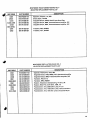
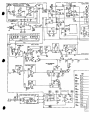
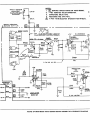
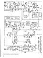
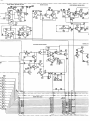
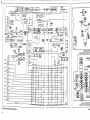
10-1
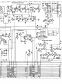
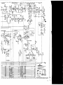
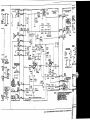
Minitmoog Schematic Diagram
51
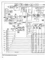
10-2
Minitmoog Block Diagram
52
10-3
Minitmoog Printed Circuit Board Assemblies
52
10-4
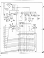
Minitmoog Touch Sensor Board Assembly No. 4 Schematic Diagram
53
10-5
Minitmoog Oscillator Board Assembly No. 5 Schematic Diagram
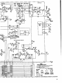
53
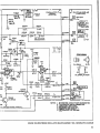
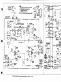
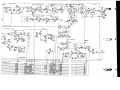
10-6
Satellite Schematic Diagram
54
10-7
Satellite Printed Circuit Board Assemblies
55
10-8
Satellite Block Diagram
56
l'i
14
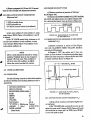
SECTION 1
INTRODUCTION
This manual provides servicing and parts infor
of which depends on which key is depressed. In
mation for Minitmoog Synthesizer Model 300A and
Satellite Synthesizer Model 5330, manufactured by
Moog Music Inc., 2500 Walden Avenue, Buffalo,
New York 14225. This manual was written basically
for the Minitmoog Synthesizer which includes the
addition, the keyboard produces a trigger voltage
touch sensor board 4 and oscillator B board 5 not
time a key is depressed. One contour generator
found in the Satellite Synthesizer. Differences in
sweeps one of the filters while the other sweeps the
whenever one or more of the keys are depressed. The
modulating oscillator produces triangular waveforms
for modulating the oscillators and filters. Two contour
generators produce voltages that rise and fall each
operating control panel markings are indicated in
amplifier. A resistor matrix determines the nominal
Section 5. Any major differences will be noted. The
values of the voltage-controlled parameters. The
Minitmoog and Satellite Synthesizers are monophonic
power supply delivers ± 18 volts unregulated and
live performance synthesizers intended primarily as
auxiliary instruments for keyboardists and features
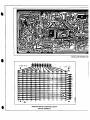
± 9 volts regulated. Refer to page 52.
a dozen "QUICK-SET" tabs that allow for instan
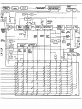
The resistor matrix has fifteen input rows and
taneous changes among various voices preset with
twelve output columns. A row is on when +9 volts is
in the instrument.
applied to it and off when it is open circuited. The two
The sound producing chain of the Synthesizers
upper rows are connected to the 2 OCT and 1 OCT
consists of an "A" oscillator that produces both
tab switches, respectively, and shorten the contour
sawtooth and rectangular waveforms, a "B"
times and raise filter frequencies when on. The
remaining rows are for the quick set voices and only
scillator (Minitmoog only) that produces only saw
tooth waveforms, a band pass filter, a low pass filter
one can be on at a time. The column outputs are
and a variable gain amplifier. All five of these circuits
in the sound producing chain are voltage controlled
applied to low impedance points in the circuitry. Of
the twelve matrix output columns, eight supply
and the remaining circuitry is devoted to producing
control currents for continuously variable parameters,
appropriate control voltages. The keyboard circuit
while the remaining four supply switching current to
produces one pitch control voltage, the magnitude
determine circuit states.
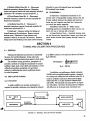
SECTION 2
CIRCUIT DESCRIPTION
GENERAL
2.2
The main circuit board mounts underneath the
Synthesizer circuitry. All connections to this board
The unregulated portion of the power supply is
located on power supply board No. 2 and is completely
conventional. The nominal total load supplied from
are made through Molex connectors. Looking at the
board from the component side with the connectors
The positive and negative voltage regulator circuits for
along the top edge, the left connector is designated
the power supply are located on main board No. 1 .
2.1
keyboard and contains a large portion of the
POWER SUPPLY
each of the unregulated voltages is 45 milliamperes.
"A" and the right connector is designated "B" with
the pins numbered from 1 to 24 starting with the
The positive power supply voltage regulator
ief t pin on each connector. Block diagrams, schematic
consists of IC1 and associated components and its
diagrams and printed circuit board diagrams are
circuitry is completely conventional. The supply
illustrated in Section 10 for quick reference.
delivers 55 or 60 milliamperes before voltage
15
developed across current sense resistor R2 limits the
current.
The negative power supply voltage regulator
consists of IC2, Ql and associated components and
adjusts its output to have the same magnitude as the
regulated +9 volt output. No current limiting, other
than that supplied by R8, is provided.
2.3
KEYBOARD CIRCUIT
The keyboard circuit consists of IC3 thru IC7,
IC9, IC10 and related circuitry. The keyboard
contains a string of thirty-six 100-ohm resistors
connected between pins A5 and A6. The current
through the resistor string is regulated by IC7 so that
the drop across R79 and R80 is exactly 4.5 volts.
R79 is set so that the voltage at pin A6 is exactly
-4.5 volts.This sets a scale factor of 3 volts per
octave (250 mv per semitone).
2.3.1 TRIGGERING (SINGLE)
The voltage at the keyboard buss is applied to
voltage follower IC4. The keyboard buss voltage
rises to approximately 7 volts (detail A, Figure 2-1)
when no key is depressed because of R53. The output
of voltage follower IC4 is applied to comparator IC5
whose output swings from -16 to +7 volts whenever
the input goes below +4.8 volts (detail B). Q5 and Q6
comprise a monostable multivibrator producing a
pulse of approximately 20 milliseconds duration
(detail C). When the output of IC5 swings positive, a
positive spike is applied through C7 and D7 to the
base of Q6, initiating a 20 millisecond pulse. R63,
R73 and R72 are proportioned so that Q7 conducts
only when the output of IC5 is positive and the output
of the monostable multivibrator (the collector of Q5)
is negative. That is, Q7 begins to conduct approxi
mately 20 milliseconds after a key is depressed and
stops conducting as soon as all keys are released.
When Q7 conducts, Q8 is turned on and the voltage
at its collector rises from 0 to +9 volts. When this
happens, C13 discharges through R61 producing a
ramp voltage at the base of Q4 that decreases from
+9 volts to -0.6 volt in approximately 20 milliseconds
(detail E). Emitter follower Q4 supplies a current
through R62 and Q3 to turn on IC10. IC10 and Q51
with associated circuitry comprise a sample and hold
circuit. When the current ramp is applied to pin 5 of
16
IC10, the voltage at the source of Q51 rapidly
approaches that at the output of IC4. As soon as the
base of Q4 drops below 0.8 volt, the bias current
being applied to IC10 through Q3 drops to zero and
the voltage at the source of Q51 remains constant.
As long as the output of IC5 remains positive (that is,
as long as any key is depressed), a very small bias
current of approximately 50 nanoamperes flows
through R59 allowing IC10 to supply a small current
to C5 keeping its voltage constant. As soon as all
keys are released, the output of IC5 goes negative
and IC10 is virtually completely shut off. Thus,
when only one key at a time is depressed, the
voltage at the source of Q51 begins to approach the
new key voltage approximately 20 milliseconds after
the key is depressed and this voltage is equal to the new
key voltage well before the ramp current turning IC10
on goes to zero. As long as a key is depressed, the
correct voltage at the source of Q51 is maintained by
the small trickle current going through R59. When
the key is released, the trigger output at the
collector of Q8 drops to zero, and the sample and
hold circuit no longer samples the keyboard voltage.
The 20 millisecond delay supplied by Q5 and Q6 is
necessary to bypass the effect of contact bounce
during key depression.
2.3.2 TRIGGERING {MULTIPLE)
IC6 becomes important when two keys are de
pressed. Any abrupt change in voltage at the output
of IC4 is applied through R66 and C10 to the input
of IC6. Cll filters out spikes less than 1 millisecond
that are associated with contact bounce or spurious
interference. The resulting rounded pulse is amplified
by IC6 (detail G, Figure 2-1). Whenever the keyboard
buss voltage increases, the output of IC6 goes
positive, D9 conducts and fires Q6 producing a 20
millisecond positive going pulse at the collector of
Q5. While this 20 millisecond pulse is on, the trigger
voltage at the collector of Q8 drops to zero. Also,
the collector of Q50 drops to zero. This causes C13
to recharge to +8.8 volts at the leading edge of the 20
millisecond pulse and resets the contour generators
which are described later. Thus, when a key is held
down and a higher key is depressed, the keyboard
sample and hold circuit again samples and the trigger
is reset momentarily. The same happens when a
higher key is released while a lower key is being held
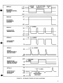
DETAIL A
~+7V
I—1ST KEY
DOWN
t2ND KEY DOWN
JD KEY UP—I
+4.5V
IC 4 OUTPUT
KEYBOARD CONTROL
VOLTAGE
1ST KEY-]
up
OV
-4.5V
+7V
DETAIL B
OV
IC 5 OUTPUT
DC KEYBOARD
DETECTOR
-16V
■20 MSEC
DETAIL C
+9V
05 COLLECTOR
TRIGGER PULSE
OV
-7V
-12V
20 MSEC
DETAIL D
+9V
08 COLLECTOR
DC TRIGGER
OV
DETAIL E
+8V
Q4 BASE
KEYBOARD SAMPLE
AND HOLD DRIVE
DETAIL F
+4.5V
SOURCE OF Q51
SAMPLED KEYBOARD
CONTROL VOLTAGE
PREVIOUS
NOTE
OV
-4.5V
+8V
DETAIL G
-I I*— 1.5
MSEC
+ 1.5V
OUTPUT OF IC 6
AC KEY DOWN
DETECTOR
OV
-1.5V
-8V
FIG URE 2-1
1.5V MIN
(FOR ADJACENT
\r
SEMITONES)
KE YBOA RD TRIGGER VOL TA GE WA VEFORMS
17
down since Q6 is fired by the negative going output
pulse of IC5 coupled via C9, R192, R78 and D10.
and 4 of IC11. The ratio of currents through these
two transistors in IC11 is an exponential function of
However, if the higher key is held and the lower key
the voltage difference between their bases. The current
is depressed or released, nothing will happen since the
fed into pin 1 of IC11 is kept constant by IC21 which
keyboard buss voltage remains constant. When all
maintains the voltage at pin 1 at the reference voltage
keys are released, D9 conducts and a 20 millisecond
pulse appears at the collector of Q5. However, the
appearing at the junction of R28 and R29. It ac
complishes this via current feedback to pin 3 of IC11.
output of IC5 goes negative, so that when the
The overall effect is that C38 discharge current doubles
collector of Q5 again goes negative, Q8 is not reset.
(increases 1 octave) for each 20 mv increase across
pins 2 and 4 of IC11. When 2 OCT switch is up,
2.3.3 KEYBOARD CONTROL VOLTAGE
R30 conducts and Q49 is saturated, effectively placing
the series combination of R20 and R21 in parallel
IC3 is a voltage follower whose output is the
voltage of the last key depressed. Variable resistor
R12 controls the glide rate and is connected between
pins A7 and A24. The time constant of this resistor
and C4 determines the glide rate. IC9 and Q2
with R19. The current at pin 1 of IC11 is then de
termined by the current flowing through parallel
resistors R19 and R20/R21. When 2 OCT switch
is down, R30 does not conduct, Q49 is open, and R20/
R21 are out of the circuit. Thus the current flowing
between this voltage follower and IC3 is the amount
into pin 1 of IC11 is 25 percent as much when Q49
is open as it is when it is saturated and, for the same
of input current required. IC9 is biased at a low
voltage difference between the bases, the current
current level so that input current does not result in
flowing into pin 5 is also 25 percent as much.
comprise another voltage follower. The difference
a pitch error when the glide rate potentiometer is at
its maximum resistance. The voltage at the emitter of
The lower end of C38 is applied to low-input-
Q2 determines the pitch of the audio oscillators and
bias-current voltage follower IC12/Q46. The voltage
is also applied to the filters and contour generators
at the emitter of Q46 is applied to Schmitt trigger
so that as the keyboard voltage goes up, the filter
Q43 and Q44. The Schmitt trigger has a high
hysteresis factor and when the voltage descends to the
point where the Schmitt trigger fires, Q45 is turned
frequency also goes up and the contour time
constants decrease.
on and C38 is rapidly recharged. The Schmitt trigger
2.4
OSCILLATOR
begins to shut off when the recharge is approximately
66 percent complete. Because of the storage time of
IC8 is a dc summer adding pitch, one-octave
transpose voltage, a tuning voltage from the fine
Q44 and Q45, C38 is fully recharged before Q45 is
completely off.
tuning potentiometer on the rear panel, a
modulating voltage and the voltage from the touch
2.4.2 OSCILLATOR A WAVESHAPING
sensor. R14 is a temperature compensating feedback
resistor. The summation constant increases with a
temperature coefficient of approximately 3400
parts per million. The relationship between R14 and
the input resistors is such that the output of IC8
decreases approximately 20 millivolts for each
octave increase in frequency.
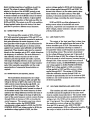
The sawtooth wave developed at the emitter of
Q46 (Figure 2-2) is applied through R41 to the base
of Q47 and through R43 to the collector of Q48. The
width of the rectangular wave that appears at the
collector of high gain amplifier Q47 depends on the
bias current supplied through R45 from the output
2.4.1 OSCILLATOR A
The oscillator A audio sawtooth waveform is
generated by linearly discharging C38 through one of
the transistors in IC11, then rapidly recharging it
through Q45. The current discharging C38 is
determined by the voltage difference between pins 2
18
FIGURE 2-2
EMITTER OF Q46
of IC13. The control current applied to the input
SYNC tab switch, the aB" PITCH control sweeps
of IC13 from the resistor matrix determines the out
the natural frequency of oscillator B over a range of
put voltage of IC13. When the control current is
more than four octaves. In this case, R505 shifts the
zero, Q47 remains saturated throughout the entire
pitch of oscillator B such that oscillators A and B are
sawtooth cycle. Q48 is also biased by IC13 (via
approximately in unison when the "B" PITCH
R118) and remains shut off and as a result, the
control is fully counterclockwise. Note that the "B"
output voltage is the undistorted sawtooth. As
PITCH control is centertapped with a center deadband
the control current increases, the voltage at the output
to allow the musician to quickly and precisely set
of IC13 goes negative. When it is approximately -1
oscillator B pitch in unison with oscillator A. Octave
volt, the current through R118 is sufficient to
trimpot R510 is set so that the pitch of oscillator B
completely saturate Q48 and effectively short out
is either an octave above or below that of oscillator
the sawtooth waves. When it is approximately -3
A when the "B" PITCH control is at either end of
volts, Q47 begins to conduct on part of the sawtooth
its rotation.
cycle and a narrow rectangular waveform appears at
its collector. When the voltage at the output of IC13
The oscillator circuitry consists of IC501,
is approximately -9 volts, the clipping of Q47 is
IC502 and Q501 with related circuitry. Q502 and
symmetrical and a square wave appears at its
Q503 are active only when oscillator B is synchron
collector. Thus, the waveform at the junction of
ized to oscillator A. A positive going pulse is
R119 and R44 is first a sawtooth when the control
produced at the output of Schmitt trigger IC502
current into IC13 is zero, then changes to a narrow
when the output voltage of integrator IC501
rectangular, then to a broad rectangular, and finally
surpasses the threshold voltage at the junction of
to a square wave as the control current is increased.
R514 and R531. Q501 is turned on for approximately
This waveform is applied to the band pass filter via an
10 microseconds. Trimpot R511 increases the
attenuator network associated with oscillator board
frequency at high charging currents and is used as a
No. 5 (oscillator B).
high end tuning adjustment. The sawtooth waveform
appears at the output of IC501.
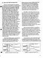
2.4.3 OSCILLATOR B (Minitmoog Only)
Sync pulses from oscillator A are applied at pin
The circuitry for the second oscillator is located
R to the base of Q502. When +9 volts are connected
on oscillator board No. 5 and consists of a current
to pin Q by the SYNC tab switch, Q502 is always
source network, sawtooth oscillator and a mixing
saturated. When pin Q is grounded by the SYNC tab
network for combining the A and B oscillator tones.
switch, the sync pulses turn Q502 off and Q503 on
The sawtooth waveform is produced by charging
once for every cycle of oscillator A. When Q503
C503 through line P and discharging it by turning on
conducts, the threshold of IC502 drops to 0 and the
Q501. The current through line P is supplied from
oscillator B waveform starts over (Figure 2-3).
one of the transistors in IC11 on the main board.
This particular transistor is located on the same chip
with the current source transistor for oscillator A
Resistors R522 thru R525 form the mixing
network. The A/B MIX control on the front panel
and its characteristics are very close to those of the
oscillator A current source. As a result, the ratio of
oscillator A to oscillator B currents will be fairly
constant as the instrument's pitch is varied.
Resistors R501 thru R510 supply a relatively small
voltage change at pin M to vary the ratio between
oscillator currents by a factor of 4. Oscillator B
range trimpot R504 sets the center value of
oscillator B pitch. When pin T is grounded by the
f SYNC tab switch, the "B" PITCH control moves
oscillator B pitch up and down an octave relative
to oscillator A. When pin V is grounded by the
FIGURE 2-3
SYNCH RONIZA TION OF OSCIL LA TOR
B TO OSCILLATOR A
19
shunts varying proportions of oscillators A and B to
ground. The values of resistors R522 thru R525
relative to the value of the A/B MIX control are set
so that the signal power sum at pins Z and ZZ tends
contour voltage applied to R116 and the keyboard
to remain constant as the A/B MIX control is rotated.
conducts, it becomes saturated and shorts out the
The output at pin Z is the oscillator A signal applied
keyboard voltage controlling the center frequency.
pitch voltage applied through R179 and R180. The
current from column 4 of the resistor matrix deter
mines whether or not Q25 conducts. When Q25
to the normal input portion of the band pass filter via
R122 and R124. The output at pin ZZ is the oscillator
R130 and R132 are offset adjustments for
B signal applied further down the chain of the band
setting correct values of bandwidth and center
pass filter to produce a different sound character.
frequency, respectively and compensate for transistor
offset voltages, resistor variations and gain variations
2.5
BAND PASS FILTER
of IC15, IC16 and IC17.
The band pass filter consists of IC15, IC16 and
IC17 with associated components. IC16 and IC17 are
2.6
LOW PASS FILTER
identical integrators effectively connected in series and
band pass filter while the gain of IC15 determines the
The output of the band pass filter is taken from
the source of Q41 and applied across the bases of the
bandwidth (Q). These gains are set by bias currents
bottom transistor pair of IC19. This transistor pair
applied from transistor pairs Q39/Q40 and Q37/Q38,
and the two immediately following it constitute a
respectively. These transistor pairs may be compared
low pass filter whose cutoff frequency is proportional
directly to the transistor pair in ICll which determines
to the standing current. This current is determined
the frequency of oscillation. The main difference is
by the voltage difference between pin 13 (ground) of
that relatively constant currents are fed to these
IC19 and the base of Q33. The voltage at the base of
transistor pairs through R133 and R129. A precise,
Q33 is the result of cutoff frequency currents flowing
wide range relationship between output current and
through R151. These currents come from column 9
base-to-base voltage is not required of these transistor
of the resistor matrix, the BRIGHTNESS potentiom
pairs. Only reasonable repeatability and the rough
eter voltage applied to R186, FILTER CONTROL
their gains determine the center frequency of the
approximation of exponential characteristics are
INPUT jack voltage applied to R185, modulation
required.
voltage applied to R187 and filter contour voltage
applied through R117. The setting of R139 deter
2.5.1 BAND PASS FILTER CONTROL INPUTS
mines the calibration current through R140. An
increase of approximately 18.5 mv at the base of Q33
The bandwidth is determined by the voltage
difference between the bases of Q37 and Q38. The
voltage at the base of Q37 is the result of the band
results in a one octave increase in the cutoff frequency
of the low pass filter.
width control current flowing through R128. An
increase of 18.5 mv doubles the bandwidth. The
2.7
VOLTAGE CONTROLLED AMPLIFIER
one source of bandwidth control current is column 8
of the resistor matrix. The center frequency is deter
The transistor pair with common emitters on pin
mined by the voltage difference between the bases of
3 of IC20 controls the amplitude of the audio wave
Q39 and Q40. The voltage at the base of Q40 is the
result of the center frequency control currents flowing
form by variable transconductance. The current which
determines this transconductance is determined by the
through R134. An increase of 18.5 mv doubles the
voltage at pin 12 of IC20 and the resistance between
center frequency. The currents come from column
pin 13 and ground. The voltage applied to pin 12 is
7 of the resistor matrix, the BRIGHTNESS
the amplitude contour voltage and the resistance
potentiometer voltage applied to R193, the FILTER
from pin B19 to ground is the 100K VOLUME
CONTROL INPUT jack voltage applied to R184,the
control potentiometer. IC22 is a differential amplifier,
modulation voltage applied to R181, the filter
the output of which is the final audio waveform.
20
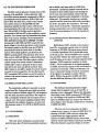
2.8 AMPLITUDE CONTOUR GENERATOR
Of the two contour generators, the amplitude
contour generator is the simplest, so it will be described
first. This contour generator consists of Q34, Q35,
difference between the bases of Q28 and Q29. Thus,
since the decay time of an envelope is generally
longer than the attack time, the voltage appearing
at the source of Q32 has an attack time inversely
proportional to the collector current of Q26. The
Q36, IC18, transistor pairs Q26/Q27 and Q28/Q29,
contributions to attack time control are similar to
Q30, Q31, Q32 and associated circuitry. When the
those of decay time control. The quick-set current
leading edge of the trigger occurs, Q35 partially
comes from column 1 of the resistor matrix.
charges C25 so that the emitter of Q35 rises to
approximately 3.5 volts. If Q36 is saturated, Q34
Since Q26 is a nearly ideal current source, the
does not conduct at all. Column 3 of the resistor
decay slope at the source of Q32 would be a straight
matrix determines whether or not Q36 is turned on.
line if not for the action of Q30. At the beginning of
If Q34 is not turned on, C25 is free to immediately
the decay slope, the voltage at the base of Q30 is
begin linearly discharging through Q26. The dis
charging current from Q26 is determined by the
more positive than the emitter, and Q30 does not
conduct. When the base of Q30 approaches -0.6
voltage control developed across R189. If Q36 is
volt (i.e., when source of Q32 is equal to +1.8
off, Q34 holds the voltage at +3.5 volts until the end
volts), Q30 acts as an emitter follower and the cur
of the dc trigger occurs (detail D, Figure 2-1).
rent through R169 flows to R189 and slows down the
Thus, the voltage at the emitter of Q35 is as shown in
decay slope. The more negative the base of Q30 goes,
Figure 2-4. The rise time of the voltage at the
the higher its control current and the more the decay
emitter of Q35 is determined only by the ability of
slope decreases. This gives the decay slope an
Q35 to discharge C25. Typically, this rise time is
extended tail and therefore sounds like a more natural
less than 1 millisecond. The decay time of the
exponential decay. (See Figure 2-5.)
amplitude contour is determined by the voltage
difference between the bases of Q26 and Q27. The
voltage across R189 results from the amplitude
contour decay time control currents coming from
column 2 of the resistor matrix, the keyboard
voltage applied to R199 and the shaping current from
R169 and R171. R190 corrects for transistor offsets
When the voltage at pin B21 is +9 volts, Q31 is
saturated and very little current flows through R171.
When the voltage at pin B21 is zero, Q31 is open and
current flows through R170 and R171 to greatly speed
up the decay slope. The SUST tab switch connects
pin B21 to +9 volts when it is down and to the trigger
increase of 18.5 mv at the base of Q26 cuts the
line when it is up. As a result, the tone is rapidly
squelched when the SUST tab switch is up and the
decay time in half.
keys are released.
and other normal component variations. A voltage
IC18, C35 and Q32 comprise a voltage follower
whose slew rate is proportional to the bias cur
rent of IC18. This bias current applied from the
collector of Q28 is determined by the voltage
r
KEY DOWN
035 EMITTER
(Q36OFF)
OV
+3.5V—
=f
-0.6V
FIGURE 2-4
controls both attack and decay times through R199
and R198, respectively. These times change by a factor
of approximately 2.5 over the complete keyboard range.
h-KEYDOWNh— KEY
KEY UP
-0.6 V
Q35 EMITTER
(Q36 ON)
0V
As noted previously, the keyboard pitch voltage
EMITTER VOL TAGE OF Q35
UP
+3.5V
Q32 SOURCE
(Q36OFF) 0V
-0.6V
+3.5V032 SOURCE
(Q36 ON)
OV
-0.6 V
FIGURE 25
SOURCE VOL TAGE OF Q32
21
2.9
FILTER CONTOUR GENERATOR
The filter contour generator contains most of the
rod on which a key bears when it is fully down
(bottomed). Excess key pressure forces the rod to
compress its foam rubber support pad causing the
features of the amplitude contour generator. Q15
of the filter contour generator corresponds to Q35 of
the amplitude contour generator, Q13 to Q34 and
rod to come into more intimate contact with the
Q12 to Q36. The filter decay mode control voltage
capacitor and the more force with which one holds a
from matrix column 11 through R88 and R91
determines whether the filter contour will rise and
then immediately fall or fall only upon release of all
key down, the greater the capacitance. The touch
keys. Q9 and Q10 of the filter contour generator
from 0 (no excess pressure) to .+6 volts (maximum
corresponds to Q26 and Q27 of the amplitude contour
pressure).
grounded conductive nylon strip glued to the foam
rubber pad. The assembly functions as a variable
sensor circuit on board No. 4 senses this capacitance
increase and produces a dc control voltage ranging
generator. The current from Q10 determines the decay
time of the contour. Similarly, IC14 corresponds to
IC18, Q18/Q19 corresponds to Q28/Q29 and Q16
corresponds to Q30. R95 and R101 couple the key
board voltage to the attack and decay control circuits.
2.11.2 VARIABLE FILTER AND AVERAGE VALUE
DETECTOR
Multivibrator IC401, located on touch sensor
The voltage applied to pin B18 from the ATTACK
board No. 4, produces a square wave at a nominal
potentiometer varies the attack time of the filter
frequency of 100 KHz. The touch sensor element
contour. The voltage applied to pin 813 from the
is a variable capacitance (C410) connected across
DECAY potentiometer varies the decay time of the
pin E and ground. C410 and R402 form a variable
filter contour. Q22 and Q23 are routing switches and
low pass filter wherein the peak-to-peak voltage at
only one is on at a time. The filter contour routing
pin E decreases as the value of variable capacitor C410
control voltage from matrix column 5 determines
increases. C402 couples the waveform to clamp
CR401. The dc component of the signal appearing
at CR401 becomes less negative as the touch sensor's
whether Q17 is open or saturated. If Q17 is open,
then Q21 is also open and Q24 is saturated. Thus,
Q22 is biased on and Q23 is biased off and the contour
capacitance is increased. R403 and C403 filter out
is routed to the low pass filter. On the other hand if
the ac components leaving only the dc component
Q17 is saturated, Q23 is biased on and the contour is
of the signal to be applied to emitter follower
routed to the center frequency control input of the
Q401. R404 at the emitter of .Q401 and C404
band pass filter.
provide additional filtering of the output signal.
2.10 MODULATION OSCILLATOR
2.11.3 DC RESTORER
The modulation oscillator is mounted on power
The keyboard circuitry generates a trigger
eters and consists of Schmitt trigger IC1 and integrator
voltage which is applied to pin A of board No. 4
whenever a key is depressed. With no key depressed,
IC2 with their associated components. The output of
this voltage is zero, Q403 conducts and IC402 turns
supply board No. 2 along with seven slide potentiom
IC2 is a triangular waveform and the output of IC1 is
a square wave. The current supplying integrator IC2,
and therefore the oscillator frequency, is varied over
the frequency range of 1 to 50 Hz by RATE control
on. The voltage at the junction of R404 and R406
(pin 2 of IC402) is kept very close to zero when the
input trigger is zero through a feedback loop consisting
of Q402 and R406.
RIO.
Whenever any key is depressed, the trigger
2.11 TOUCH SENSOR
voltage at pin A rises to +9 volts and Q403 shuts off,
shutting off IC402. C405 holds the voltage that
2.11.1 MECHANISM
existed before the trigger appeared and the
junction of R406 and R404 remains close to zero
The touch sensor mechanism, mounted under
neath the keys, has a 20 inch long anodized aluminum
22
until the touch sensor element capacitance increases.
When the element's capacitance begins to increase
The touch control output at pin G rises from 0
(as a result of pressing down harder upon a key), the
voltage at the junction of R404 and R406 begins to
to approximately +6 volts and sweeps the filters, both
-i$e. Thus IC402, Q402, Q403 and related circuitry
oscillators or just the second, oscillator depending on
yrnPa dc restorer that keeps the voltage at the
how the front panel touch sensor switches are set.
junction of R404 and R406 at zero until a key is
depressed and returns it to zero when a key is released.
2.11.5 MODULATION AMOUNT
2.11.4 AMPLIFIER
The touch control output from pin 6 of IC403 is
The voltage at the junction of R404 and R406
also applied through R411 and Q404 to control the
is applied to open loop amplifier IC403. The value
gain of IC404. The triangular modulation wave is
of R408 is set so that the input of IC403 begins to
applied at pin H from the output of IC2. The modu
saturate when the touch control output rises to ap
lating signal of varying amplitude at pin J is available
proximately 50 percent of its maximum value and
for modulation when the TOUCH CONTROLS MOD
saturates more and more as the touch sensor element
tab switch is depressed. It should be noted that the
is depressed further* This allows the touch sensor to
ratio between R412 and R413 is set so that C409
be more sensitive at the beginning of its travel and to
rounds off the triangular wave to yield a desirable
become increasingly less sensitive as a key is depressed
sinusodial wave effect.
with more force.
SECTION 3
DISASSEMBLY, VISUAL INSPECTION AND REASSEMBLY
3.1
DISASSEMBLY
3.2
Disassembly and inspection are essentially the same
VISUAL INSPECTION
a) Inspect instrument for broken wires, loose
for both Synthesizers except where the Touch Sensor
Board 4 and the Oscillator Board 5 are mentioned.
printed circuit boards or electrical connectors, cable
These boards are used only on the Minitmoog.
pots with terminals shorted to chassis.
harness wires pushed into keyswitches and rotary
b) Check for frayed conductive nylon on touch
a) Disconnect power cord connector and all
sensor assembly shorting to keyboard switch assembly.
other rear panel connections.
b) Stand instrument on one ei.d and remove
three screws securing large bottom cover (Figure 3-1)
3.3 PRINTED CIRCUIT BOARD REMOVAL
to instrument using a medium sized Phillips head
screwdriver and remove cover.
a) Main Board No. 1 - Disconnect 5 electrical
connectors, depress levers on 6 fastening devices and
NOTE
All internal alignment and adjustment
controls are now accessible.
c) If necessary, the narrow bottom cover may be
remove board from bottom cover. (See Figure 3-1.)
b) Power Supply Board No. 2 - Remove 7 slide
knobs, narrow bottom cover, 2 electrical connectors,
2 screws and 1 foot and carefully lift power supply
from instrument.
removed by taking out an additional 10 screws.
WARNING
WARNING
Removing narrow bottom cover exposes
Removing narrow bottom cover exposes
live terminals of the ac POWER tab
live terminals of the ac POWER tab
switch. Use extreme care when power
switch. Use extreme care when power
cord is connected to primary power.
cord is connected to primary power.
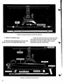
23
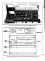
TOUCH SENS.OR BOARD NO. 4
"B" OSCILLATOR BOARD NO. 5
POWER SUPPLY BOARD NO. 2
MAIN BOARD NO. 1
MATRIX BOARD NO. 3
. (NOT VISIBLE)
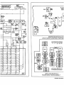
FIGURE 3-1 MINITMOOG PRINTED CIRCUIT BOARD LOCATIONS (INSIDE VIEW)
RESISTOR
MATRIX
BOARD NO. 3
D
CONNECTORS
B
CONNECTORS
D
CONNECTOR
MAIN BOARD NO. 1
OSCILLATOR BOARD NO. 5 (MINITMOOG ONLY)
e
©Do
e
©
0
CONNECTORS
TOUCH SENSOR BOARD NO. 4 (MINITMOOG ONLY)
\
POWER
SUPPLY BOARD
NO. 2
C.'.T
\
KEYBOARD
rz-v x-
FIGURE 3-2 MINITMOOG COVER AND PRINTED CIRCUIT BOARD LOCATIONS (BOTTOM VIEWS)
24
c) Resistor Matrix Board No. 3 — Disconnect
electrical connector, depress levers on 4 fastening
devices and remove board with cable assembly attached.
Jisconnect "D" connector on main board No. 1.
d) Touch Sensor Board No. 4 — Disconnect
electrical connector, remove 2 nuts and carefully lift
board from instrument.
L-bracket to rear of keyboard frame and carefully
lift keyboard from chassis.
3.4
REASSEMBLY
a) Keyboard - Reassemble keyboard in the
reverse order of disassembly making certain that the
2 large washers between the chassis and keyboard
frame are not forgotten and that the 2 screws do
e) Oscillator Board No. 5 — Disconnect 2
electrical connectors, remove 2 nuts and carefully lift
board from main board No. 1.
not touch the sensor assembly.
b) Oscillator Board No. 5 - Make certain
insulating spacers are reinstalled so that nuts do not
f) Keyboard — Remove cabinet by taking out
4 small screws on the end pieces. Remove narrow
short out top or bottom side of board.
c) Large Bottom Cover - Ascertain harness wires
bottom cover. Disconnect 1 snap fastener and
are not forced into keyswitches. Assure cover does not
unsolder 3 wires (1 at top and 2 at bottom). Remove
pinch matrix harness wires passing through cutout in
2 large screws and washers, 2 hex head screws securing
chassis.
SECTION 4
TUNING AND CALIBRATION PROCEDURES
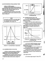
4.1
GENERAL
Tuning and calibration procedures are essentially
the same for both Synthesizers. Unless otherwise
to as REF) tunable a few semitones above and below
Bb4 (466 Hz).
indicated the following instructions apply to both units.
The oscillator tuning procedure, paragraph 4.2,
REFERENCE=
provides a method of tuning the instrument for proper
oscillator range, scale, octave shift and tracking. A voice
= 466Hz
calibration procedure, paragraph 4.3, provides a
method of calibrating the sound modifying circuits
In addition, an oscilloscope, digital voltmeter
to voice the presets.
(DVM) and an amplifier/speaker system is required
4.2
for tuning and calibration and oscillator board No. 5
OSCILLATOR TUNING
must be carefully raised (not disconnected) from
main board No. 1 to gain access to trimpots R16
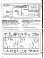
4.2.1 TEST SETUP
and R190. The minimal test setup shown in Figure
A stable oscillator (or another synthesizer) is
required to provide a reference tone (hereafter referred
FIGURE 4 1
4-1 will suffice. However the setup shown in Figure
4-2 will prove to be much more convenient and
MINIMAL TEST SETUP FOR TUNING
25
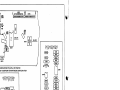
FIGURE 4-2
TWO CHANNEL OSCILLOSCOPE TEST SETUP FOR TUNING
should be used if a two channel oscilloscope is
of oscillator board No. 5 and turn +9 volt adjust trimpot
available. In the test setup of Figure 4-2, display
R4 on main board No. 1 (Figure 4-3) until the +9 volt
height and audio level are independent and it is not
line is exactly +9.000 V ±10 mv.
necessary to trigger the oscilloscope off of a composite
b) Connect DVM across pins L (-) and K (+) of
waveform. Trigger the oscilloscope off the lower
oscillator board No. 5 and verify that the -9 volt line is
of the two frequencies.
-9.000 V ±200 mv.
4.2.2 POWER SUPPLY ADJUSTMENT (Minitmoog Only)
4.2.3 KEYBOARD CURRENT ADJUSTMENT
a) Connect DVM across pins J (+) and K (-)
KEYBOARD
ADJ
R79
OCT1
ADJ
RIO
a) Connect DVM across pins A5 (+) and A6 (-)
OSCILLATOR
A HIGH
SCALE
FREQUENCY
R17
+9V ADJ \VIBRATO ADJUST
/
R14
RANGE
R16
AMPLITUDE
DECAY
R190
UNDER
IC11
VCA
BAL
R160
JUNCTION
R165ANDR166
AMPLITUDE
R162
IC22
\
\
\
ATTACK
R174
0
08 /
R47
R64 SQUARE
WAVE ADJ
JUNCTION R130
OF R44
ANDR119
BAND
WIDTH
ADJUST
R21
\ Q41
ADJ
JUNCTION
R149 AND C30
OCT2
\
R132
CENTER
FREQ
ADJ
Q20
\
R98
R139
R105
FILTER LOW PASS FILTER
DECAY CUTOFF ATTACK
FIGURE 4-3 MAIN BOARD NO. 1 ADJUSTMENT CONTROLS AND OSCILLOSCOPE TEST POINT LOCA TIONS
26
of main board No. 1 and observe voltage drop
d) Center the rear panel TUNE control, connect
across keyboard.
b) Adjust keyboard trimpot R79 (Figure 4-3) for
wiper to ground, place 1 OCT tab switch down and
a voltage indication of +9.000 V +10 mv.
tom of R14, Figure 4-3) and ground. Adjust range
connect DVM test leads between pin 6 of IC8 (bot
trimpot R16 for an indication of 0.0000 +0.0001 V.
4.2.4 TRIGGERING
a) Connect oscilloscope to the collector of Q8
(Figure 4-3) and verify that the trigger voltage wave
form present is as shown in Figure 4-4 with a single
key depressed.
b) Hold one key down, depress next higher key
and verify that a retrigger occurs.
-20 MSEC
4.2.7 OSCILLATOR SCALE
+9V-
1 OCT tab switch down
2 OCT tab switch down
OV-
KEY UP—
KEY DOWN-*
a) Adjust REF frequency for zero beat with
FIGURE 4-4
TRIGGER ATCOLLECTOR OF Q8
oscillator A. Normally the REF frequency will be
between 430 and 500 Hz and the Synthesizer fre
4.2.5 KEYBOARD DRIFT
quency will be two octaves lower (nominally 117 Hz).
b) Hold down high Bb key (highest black key) and
and verify the keyboard pitch voltage ranges from
zero beat oscillator A with REF frequency using scale
trimpot R17 (Figure 4-3, Synthesizer =* 233 Hz,
-4.50 V +100 mv at the lowest key to +4.50 V
1 octave below REF frequency).
a) Connect DVM to emitter of Q2 (Figure 4-3)
+100 mv at the highest key.
b) Verify that the pitch voltage holds steady
while a key is being depressed and after the key is
4.2.8 OSCILLATOR A HIGH FREQUENCY COMPENSATION
released. In neither case should the drift exceed
25 mv per minute.
1 OCT tab switch up
2 OCT tab switch up
4.2.6 PREPARATION FOR OSCILLATOR A TUNING
(MAIN BOARD NO. 1)
a) Place all tab switches and slide controls up,
turn all potentiometers counterclockwise and place
VIOLIN tab switch down.
b) Connect a jumper between the collector and
base of Q3 (Figure 4-3) in order to keep IC10 on and
thereby eliminate keyboard control voltage drift.
c) Hold down the middle B(, key (14 semitones
below topmost key) for oscillator A tuning.
a) Adjust REF frequency to zero beat with
oscillator A (Synthesizer =* 932 Hz, 1 octave above
REF frequency).
b) Hold down the high B(, key and zero beat
oscillator A with the REF frequency using the
oscillator A high frequency trimpot (Figure 4-3,
tacked on to the left of R21). Repeat steps a and b
several times.
27
NOTE
Repeat paragraphs 4.2.7 and 4.2.8 several
times as the adjustments interact, i.e., each
time the scale is reset, the high frequency
e) Set A/B MIX control to vertical so that
the pitch of oscillators A and B may be compared.
4.2.12 OSCILLATOR B SCALE (Minitmoog Only)
will go off frequency and vice versa. The
process converges quickly so that both
1 OCT tab switch up
adjustments can be accurately set.
2 OCT tab switch down
"B" PITCH control full CCW
4.2.9 OSCILLATOR A OCTAVE TRANSPOSITION
a) Zero beat oscillator B with oscillator A using
1 OCT tab switch down
range trimpot R504, Figure 4-5 (oscillator B will be
2 OCT tab switch down
1 octave lower than oscillator A).
b) Hold down highest Bj,
key and zero beat
oscillator B with oscillator A using scale trimpot
a) Adjust REF frequency for zero beat with
oscillator A (Synthesizer =* 117 Hz, 2 octaves below
R529, Figure 4-5 (oscillator B one octave below
oscillator A).
REF frequency).
b) Place 1 OCT tab switch up and zero beat
oscillator A with REF frequency using octave 1
adjust trimpot RIO (Figure 4-3, Synthesizer =* 233 Hz,
M
1 octave below REF frequency).
X
zz
N
c) Place 2 OCT tab switch up and 1 OCT tab
switch down and zero beat oscillator A with the REF
YY
L
K
J
frequency using octave 2 adjust trimpot R21 (Figure
4-3, Synthesizer =* 466 Hz, unison with REF frequency).
P
R510 .
OCTAVE
R504
RANGE
R529
SCALE
R511
HI END
4.2.10 OSCILLATOR A RANGE
1 OCT tab switch down
2 OCT tab switch up
REF frequency exactly 466 Hz
FIGURE 4-5
OSCILLATOR B TRIMPOT LOCATIONS
(BOARD NO. 5)
a) Set range trimpot R16 (Figure 4-3) so that
oscillator A zero beats with REF frequency
4.2.13
OSCILLATOR B HIGH FREQUENCY
COMPENSATION (Minitmoog Only)
(Synthesizer = 466 Hz, unison with REF frequency).
1 OCT tab switch up
4.2.11 PREPARATION FOR TRACKING OSCILLATOR B
TO OSCILLATOR A (Minitmoog Only)
2 OCT tab switch up
"B" PITCH control vertical (in deadband)
a) Perform paragraphs 4.2.6 through 4.2.10 to
tune oscillator A before tuning oscillator B (located
on oscillator board No. 5).
b) Disconnect jumper between collector and base
ofQ3.
range trimpot R504, Figure 4-5 (oscillators A and B
in unison).
b) Hold down highest Bb
key and zero beat
c) Hold down lowest Bj, key using a wedge.
oscillator B with oscillator A using high end trimpot
d) Turn off REF source since oscillator B
R511, Figure 4-5 (oscillators A and B in unison).
will be tuned by making it track oscillator A.
28
a) Zero beat oscillator B with oscillator A using
Repeat steps a and b several times.
c) Repeat paragraphs 4.2.12 and 4.2.13 several
times as scale and high end adjustments interact.
4.2.14 OSCILLATOR B OCTAVE TRANSPOSITION
(Minitmoog Only)
1 OCT tab switch down
4.3.2 SQUARE WAVE DUTY CYCLE
a) Observe waveform at junction of R44 and
R119 (Figure 4-3).
b) Depress CLARINET (REED HOLLOW, Satellite)
tab switch and adjust square wave adjust trimpot R47
for a symmetrical square wave as shown in Figure 4-6.
2 OCT tab switch up
"B" PITCH control vertical (in deadband)
EXACTLY 50%
DUTY CYCLE
a) Zero beat oscillator B with oscillator A using
range trimpot R504, Figure 4-5 (oscillators A and B
FIGURE 46 SQUARE WAVE AT JUNCTION
OF R44ANDR119
in unison).
b)Set "B" PITCH control fully clockwise to 10
and zero beat oscillator B with oscillator A using
octave trimpot R510, Figure 4-5 (oscillator B one
octave above oscillator A).
4.3.3 BAND PASS FILTER RESONANCE (Q) AND CENTER
FREQUENCY (Fc)
a) Observe waveform at source of Q41 (Figure
4-3) with CLARINET (REED HOLLOW, Satellite)
tab switch still depressed.
NOTE
Allow a small adjustment latitude by tuning
oscillator B slightly sharp in step b (approx
imately 2 Hz beat rate). Thus oscillator B
b) Depress 1 OCT tab switch and C key one
octave up from bottom of keyboard and adjust band
width and center frequency trimpots R130 and R132
to obtain waveform shown in Figure 4-7.
will be in tune with oscillator A slightly
before the control reaches full rotation.
4.3
VOICE CALIBRATION
700 USEC (Fc: R132)
4 UNITS
4: 1 RATIO (Q: R130)
4.3.1 PREPARATION
Set the following controls to their initial position
V^>»-^
1UNIT
as follows: Satellite panel marking differences are in
parentheses.
FIGURE 4-7 BAND PASS FIL TER Q AND Fc
AT Q41 SOURCE
4.3.4 LOW PASS FILTER CUTOFF FREQUENCY (FL)
a) Raise all tab switches and depress highest key
on keyboard.
b) Set VOLUME slide control all the way up and
adjust low pass cutoff trimpot R139 (Figure 4-3) until
the waveform at output pin 6 of IC22 (top of R162)
is two volts peak-to-peak.
29
4.3.5 FILTER CONTOUR ATTACK AND DECAY TIMES
a) Depress 1OCT tab switch.
^60-70.
MSEC
+3.7V.
b) Depress MUTE (BRASS MUTE, Satellite) tab
switch and observe filter contour at the source of Q20
(Figure 4-3) while repeatedly striking C key one
octave from bottom of keyboard.
c) Adjust filter decay and attack trimpots R98
and R105 until the filter contour matches the pattern
KEY DOWN-*
0V-
-20 MSEC
shown in Figure 4-8.
FIGURE 4-9
NOTE
It may prove convenient to externally trigger
the oscilloscope from the bottom of R64
for paragraphs 4.3.5 through 4.3.7.
LOUDNESS ATTACK A T JUNCTION
OF R165 AND R166
4.3.7 LOUDNESS CONTOUR DECAY TIME
a) Lift MUTE (BRASS MUTE, Satellite) tab
switch and depress PIANO (STRING STRIKE,
Satellite) tab switch.
b) Assure 1 OCT tab switch is still down and
depress C key one octave up from bottom of keyboard.
c) Observe waveform at junction of R165 and
R166 (Figure 4-3) and adjust amplitude decay
trimpot R190 for the decay contour shown in
~ +1.7V-
Figure 4-10.
J
ov-
-0.5V-
FIGURE 4-JO
LOUDNESS DECA Y ATJUNCTION
OF R165 AND R166
R105
ATTACK
R98
DECAY
200 MSEC ' 200 MSEC
FIGURE 4-8
FIL TER CONTOUR A T Q20 SOURCE
4.3.8 VOLTAGE CONTROLLED AMPLIFIER BALANCE
a) Lift PIANO (STRING STRIKE, Satellite)
tab switch and short junction of R149 and C30
(Figure 4-3) to ground.
b) Set VOLUME slide control at maximum and
4.3.6 LOUDNESS CONTOUR ATTACK TIME
connect oscilloscope probe to top of R162.
c) Hit and release a key and adjust VCA balance
trimpot R160 until a minimum click or thump is
a) Observe waveform at junction of R165 and
R166 (Figure 4-3) with MUTE (BRASS MUTE,
heard and step waveform at top of R162 does not
exceed lOmv.
Satellite) and 1 OCT tab switches still down.
b) Depress C key one octave up from bottom of
4.3.9 VIBRATO DEPTH
keyboard and adjust amplitude attack trimpot R174
to match the attack contour shown in Figure 4-9.
30
a) Set vibrato depth trimpot Rl fully CCW.
I
SECTION 5
OPERATING CONTROLS, INDICATORS AND CONNECTORS
Satellite Synthesizer panel marking differences are shown in parentheses.
PANEL MARKING
REF
DESIG
FILTER ATTACK
(FILTER CONTOUR)
Slide Control
R7
FILTER DECAY
R8
FUNCTION
Controls amount of time it takes for the bright
ness to reach a peak; 0 is the normal setting, -4
indicates the longest attack and +4 the shortest
attack times.
(FILTER COLOR)
Slide Control
Controls amount of time it takes for the bright
ness to die away on most voices; 0 is the normal
setting, -4 indicates the longest decay and +4
the shortest decay times.
FILTER BRIGHTNESS
(FILTER EMPHASIS)
Slide Control
MODULATION RATE
Slide Control
MODULATION DEPTH
Slide Control
R9
Determines voice clarity from dull to bright
sounds.
RIO
Varies rate of modulation from approximately
one per second at 0 to a buzz rate at 10.
Rll
Adjusts degree or intensity of modulation. With
MODULATION VIB tab switch depressed,
increasing MODULATION DEPTH corresponds
to periodic frequency deviation that increases
from zero to more than one octave. With
MODULATION TREM tab switch depressed,
increasing MODULATION DEPTH corresponds
to greater periodic timbre variation.
GLIDE
Slide Control
R12
Adjusts keyboard glide time from note to note
VOLUME
R13
Adjusts Synthesizer output level over a range of
from 0 to 4 seconds when GLIDE tab switch is
depressed.
30dB.
Slide Control
SW21
POWER Tab Switch
and Indicator Light
Controls primary power supplied to instrument.
Red indicator light indicates when POWER
tab switch is depressed and primary power
is supplied to the instrument.
"B" PITCH
Varies pitch of B tone producing oscillator over
\
Variable Resistor/
WMinitmoog
(
A/BMIX
Variable Resistor/
Only)
a two octave range.
Controls mixing of A and B tone source oscillator
outputs. A only or B only occur at the CCW and
CW extremes of rotation, respectively.
31
OPERATING CONTROLS, INDICATORS AND CONNECTORS (Cont.)
32
OPERATING CONTROLS, INDICATORS AND CONNECTORS {Cont.)
PANEL MARKING
REF
DESIG
FUNCTION
SUST
Tab Switch
SW13
When depressed, allows note to die away more
gradually after key is released.
MUTE (BRASS MUTE)
Tab Switch
SW12
When depressed, approximates a "wah-wah"
muted brass voice starting with an emphasis on
the lows, moving to the highs and returning each
time a key is depressed.
When depressed, keyboard produces the sounds
of a trumpet, trombone or tuba by depending on
various other controls.
When depressed, keyboard produces the sounds
similar to that of a double reed. In the top octave,
the sound is of an oboe. In the lower octaves, the
sound of a bassoon is approximated.
When depressed, keyboard produces the hollow
reed sound and soft attack of the traditional
clarinet.
When depressed, keyboard produces the bright
reed sounds of a saxophone.
When depressed, keyboard simulates the bass
sound characteristic of the Taurus Synthesizer.
When depressed, keyboard produces a gentle voice
with a slow attack simulating the sounds of a violin.
When depressed, keyboard produces a plucked
string voice with a lingering decay for creating
guitar or harpsichord effects.
When depressed, keyboard produces a percussive
struck string voice similar to a piano.
When depressed, produces a typical synthesizer
sound.
When depressed, produces an interesting sound
similar to that of an electric bass guitar.
This versatile voice provides a wide variety of
timbre changes which produce many popular
electronic Moog sound effects when depressed.
Tab Switch
TUNE
Variable Resistor
R237
Adjusts pitch of Synthesizer to match the pitch
of another instrument.
33
OPERATING CONTROLS, INDICATORS AND CONNECTORS (Cont.)
SECTION 6
KEYBOARD MAINTENANCE AND ADJUSTMENT
6.1
CONTACTS
6.1.1 DIRTY CONTACTS
CAUTION
Do not touch J-wires or buss bar
with bare fingers as salty, oily finger
The J-wire switch contact to the buss bar may
become dirty or corroded. If so, use ordinary rub
bing alcohol (isopropanol) on a cotton swab to
clean the contact area. Do not spray contact cleaner
prints will eventually cause corrosion
and dust collection resulting in inter
mittent operation.
onto the key contacts or use abrasives (emery paper
or burnishing tools) as they will remove the gold
plating. Be careful not to bend the J-wires (fine
6.1.2 CONTACT HEIGHT
whiskers). Stubborn cases may require cleaning
with a nonabrasive rubber eraser. If the contact
area has been damaged, rotate the buss bar or Jwire or gently bend the J-wire laterally to contact
gering of notes. Triggering problems may also occur
a new portion of the buss bar.
34
Dirty contacts are revealed by improper trig
if the contact height (the distance tip of key travels
downward before the note sounds) is set too high
(i.e., makes contact too soon). Black keys should
make contact between 1/8 and 3/16 inch of down-
ward travel and white keys between 3/16 and 1/4
inch. If necessary, rebend by gently massaging the
assembly and not on the key leveling tabs. The
5 studs are locked into position by 10 nuts on
portion of the wire between the actuator and the
either side of the keyboard frame. The sensor is
attachment point. The contact must make before
intentionally warped by the extreme end studs
the key bottoms on the touch sensor assembly.
when mounted so that its ends are approximately
1/16 inch further away from the keyboard frame
6.2
KEYS
6.2.1 CLANKING
than its center. This must be accomplished before
the keyboard is installed in the chassis. The warp
ing must be accomplished so that touch sensitivity
for keys at the ends of the keyboard is the same
Keys will clank or thump if the tails hit the
case on the down stroke. This problem can be
repaired by gluing a thin spacer such as a 1/16
inch thick piece of wood to the case immediately
as that for the keys in the center. If this is not
accomplished, the center keys will be overly sen
sitive while the end keys will not have enough
response.
above the plastic strip over the key pivots. The
case will be forced away from the keys upon
6.3.2 ADJUSTING SCREWS
reassembly and clanking should cease.
Two slotted screws set the pressure with which
6.2.2 STICKING OR SLUGGISH FEEL
the rod bears against the foam pad. Adjust these
screws as follows:
Check the pivot for being too tight. Rotate
the pivot tab about the vertical axis by bending a
1 OCT and 2 OCT tab switches up
few degrees with a pair of pliers. Make certain the
key tails are not rubbing on the back of the case
VIOLIN and PITCH tab switches down
necessitating the removal of some of the wood with
TOUCH SENSE variable resistor
full clockwise
coarse sandpaper. Keys near either end of the key
board may stick because the hex head screw that
Play over the entire keyboard "with a normal
fastens the rear mounting brackets to the keyboard
light playing touch. If unwanted pitch bending
frame does not have its flats aligned vertically. In
this case, the screw head will rub against the key
occurs, tighten slotted screws by turning counter
return springs and cause the trouble.
pressure is applied to the keys.
6.2.3 LEVELING
will not be responsive enough. The pitch should
clockwise until bending occurs only when extra
If the screws are over tightened, the sensor
If a key does not return to the same height
as its neighbors, the key leveling tab located inside
the front end of the metal body of the key must
be bent up or down as required. Remove the key
screw so the ivory comes off and reposition the
tab using the keyboard adjusting tool, part number
962-043031-001.
6.3
TOUCH SENSOR
6.3.1 SENSOR MOUNTING
The touch sensor assembly is mounted to
the keyboard frame by 5 studs attached to the
sensor assembly. The height of the assembly must
be set so that the keys will bottom on the sensor
bend upward at least a fifth (7 semitones) for any
key pressed down heavily. Especially check the
keys near each end of the keyboard as they nor
mally will be less responsive. If necessary, loosen
screws slightly by turning clockwise and recheck
for over sensitivity.
6.3.3 TOUCH SENSOR INTERMITTENT OPERATION
WHEN DEPRESSED OR TOUCH SENSOR DEAD
This trouble may be due to open contacts
between the shielded cable and either the con
ductive nylon (snap fastener) or the touch bar
(No. 6 screw in end) or there may be a short between
the touch bar and the nylon. Shorts may occur
around the two holes in the rod through which the
35
adjusting screws pass or at the end of the rod if
the No. 6 screw touches the nylon. Repair these
shorts by sticking a small piece of Scotch No. 156
the key contacts. In addition, check for a strand of
2 mil mylar tape over the area of the short. Burn
bending pitch, the pitch drifts down at an objec
a hole in the tape with a soldering iron for the
adjusting screw. If the nylon is frayed, look for
a strand touching either end of the buss bar caus
tionable rate while the key is pressed down fully,
ing a short circuit. Repair this by burning off the
several CA3080s until one with the proper charac
strand with a soldering iron.
teristics is located.)
frayed conductive nylon contacting the key switches
causing nonf unctioning or crazy operation. If when
replace IC402. (IC402 is a factory selected part
requiring a CA3080 with low output leakage. Try
Sometimes the audio output may die out
completely when a key is pressed down hard. This
6.3.4 OTHER DIFFICULTIES
trouble may be caused by one of the 5 mounting
studs contacting the top of a socketed CA3080
If one, several or all of the keys are inoperative,
make certain the wiring harness is not pushed into
36
metal can on the main board. If this occurs, shorten
the CA3080 leads, studs or both as required.
SECTION 7
TROUBLESHOOTING GUIDE
The procedures that follow generally apply to both Synthesizers except where the Oscillator Board 5 and
Touch Sensor Board 4 are mentioned. These components are used only on the Minitmoog. An aid in control
selection is presented in Section 5 indicating the different panel markings for identical controls.
37
TROUBLESHOOTING GUIDE (Cont.)
SYMPTOM
PROBABLE CAUSE
7.2 SOUND CHAIN
Set the following controls as follows for all sound chain troubleshooting procedures.
All tab switches up except VIOLIN tab switch down.
All slide controls at zero position except VOLUME slide control at 10.
All front panel rotary controls full counterclockwise position.
A.
B.
No sound and POWER indicator
light off.
1.
No sound, POWER indicator
light on and 9 volt power supplies
1.
operating properly.
2.
115 VAC wiring faulty.
POWER switch SW21 defective.
Connect oscilloscope probe to emitter of Q46 and verify
oscillator A is operating properly.
2. Connect oscilloscope probe to pin 6 of IC501 and verify
oscillator B is operating properly.
3. If both oscillators are operating properly, set A/B MIX
control vertical and check waveforms on pins Z (oscillator
A) and ZZ (oscillator B) of board No. 5 (Figure 4-5).
Levels should cross fade as A/B MIX control is rotated.
Trouble would most likely be caused by faulty wiring
from pins S, X, Y, Z or ZZ. If only oscillator A is not
operating, trouble may be in waveform selector circuit.
If proper waveforms are observed on pins Z and ZZ,
proceed to step 4.
4.
Check band pass filter output waveform at source of Q41.
Signal level should be approximately 300 mv peak-topeak. No output indicates trouble is in band pass filter
section. If proper output is observed, proceed to step 5.
5. Check low pass filter output waveform at pin 1 of IC20
with a key depressed. Signal level should be approxi
mately 400 mv peak-to-peak. If not, trouble is in the
voltage controlled filter or amplifier (IC19 or IC20). If
proper waveform is observed, proceed to step 6.
6. Check waveform at pin 6 of IC22 while holding a key
down. Signal level should be approximately 3 volts peakto-peak. If normal, trouble is in output wiring, R236, J3,
J4 or associated circuitry. Otherwise IC22 or associated
circuitry is faulty.
C.
Intermittent sound or sound
dies when key is depressed
1.
firmly.
2.
Keyboard shorting to top of a CA3080 integrated circuit
can. Shorten leads or touch sensor mounting studs.
Harness wiring or rotary control lug shorting to front
panel extrusion.
D.
Neither oscillator A or B
operating.
1.
2.
3.
Faulty exponential current source IC11 or IC21.
IC8 or associated dc summer circuitry faulty (possible
shorted summing resistor).
Resistor R14 broken.
4. Improper input to dc summer input resistors.
38
TROUBLESHOOTING GUIDE (Cont.)
PROBABLE CAUSE
SYMPTOM
7.2 SOUND CHAIN (Cont.)
E.
F.
G.
H.
No oscillator B output,
1.
IC501, IC502, Q501, Q502 or Q503 defective.
oscillator A operating
2.
Input wire to board No. 5 broken.
properly.
3.
4.
Resistor R501 broken.
Connector pin M, R or P shorted.
5.
IC11 defective.
No oscillator A output,
1.
IC12, Q43, Q44, Q45 or Q46 defective.
oscillator B operating
properly.
2.
Open OSC A HI END trimpot.
3.
Capacitor C38 shorted.
No waveshaper output.
1.
IC13, Q47 or Q48 defective.
2.
Resistor R47 open.
3.
Faulty wiring to pin D6 of resistor matrix.
1.
Ground collectors of Q38 and Q39. If signal still does
not pass, trouble is in IC15, IC16, IC17, Q41 or Q42 or
associated circuitry. If signal passes the filter, check
Band pass filter will not
pass signal.
filter control current sources.
I.
Band pass filter current
1.
sources at fault.
Remove one short and then the other to determine
which transistor pair, Q37 and Q38 or Q39 and Q40,
is faulty.
2.
Ground both transistor bases of the faulty pair and
observe if signal passes (collectors not shorted). If signal
passes, the fault lies in the summing network, matrix or
matrix interconnecting wiring. Otherwise the transistor
pair or trimpot is at fault.
J.
Low pass VCF and VCA
do not pass signal (no
signal on pin 1 of IC20).
1.
Short pin 14 of IC19 to ground. If signal passes, the
fault is in either the filter contour circuitry or the
transistor the collector of which is tied to pin 14. If
signal still does not pass, proceed with step 2.
2. With pin 14 of IC19 still shorted to ground, measure
waveform at pins 7 and 10 of IC20. Signal at each pin
should be approximately 10 mv peak-to-peak (about
hah' the 20 mv peak-to-peak observed at pin 2 of IC19).
If signal is present, VCF is operating properly arid the
problem lies within the VCA. If signal is not present,
trouble is in IC19.
K.
Low pass VCF operating
properly (proper signals at
1.
pins 7 and 10 of IC20) but
VCA has no output (pin 1
of IC20).
Hold down a key and check that voltage at pin 12 of
IC20 holds at approximately +3.5 VDC. If voltage
holds, trouble is in IC20, R164, VOLUME control R13
or wiring from R164 to R13. If voltage at IC20 does
not rise, the amplitude envelope generator is not
functioning.
L.
VCA operating properly
but has no output.
1.
Trouble is in IC22, C32, LEVEL ADJUST control
R238 or output wiring.
39
TROUBLESHOOTING GUIDE (Cont.)
41
SECTION 8
MODIFICATIONS
8.1
1. Remove the touch sensor from the unit by
SERVICE BULLETIN 802
removing the bottom cover and unscrewing four
This Service Bulletin was issued and is included
in this manual to avoid future maintenance because
screws (Figure 8-1) to disassemble the unit to the
extent shown in Figure 8-2.
of defective or intermittent touch sensor bar. This
condition occurs because of a chemical reaction
between the foam and conductive nylon material.
2. Remove the five nuts from the captive screws
(Figure 8-2) securing the top support to the unit and
remove the support.
8.2
TOUCH SENSOR BAR
(Minitmoog Serial Numbers below 2144)
3. Unscrew the two screws that attach the sensor
to the top support (Figure 8-3).
Rebuilt touch sensor bars are available under
part number 997-043976-001. It is estimated to
4. Remove and discard the conductive nylon
require 1 hour to perform the following
material and the double sided tape (Figure 8-4) being
procedures:
careful to avoid damaging the foam pad.
FIGURE 8-1 DISASSEMBL Y OF MINI TMOOG
42
R EMOVE 5 NUTS
ADJUSTMENT SCREW
; RIGHT SIDE
FIGURE 8-2 MINITMOOG DISASSEMBLED
5. Apply two strips of double sided tape to
completely recover the foam pad (Figure 8-5).
wire around the two mounting holes and allow
sufficient excess wire to extend beyond the right side
of the bar to permit soldering the wire to the cable
30
6. Install a drain wire, No. 30 AWG gauge (No.
•0 buss wire), generally centered along the length of
che touch sensor bar. However, carefully route the
braid after the touch sensor bar is installed. The wire
should be slightly less than flush on the left side of
the sensor bar.
FIGURE 8-3 SENSOR REMOVAL
43
FIGURE 8-4 SENSOR REMOVED FROM TOP SUPPORT
7. Install new conductive nylon.
9. Also wrap the end of the touch sensor bar with
mylar tape at the point where the drain wire extends
8. Add mylar tape insulating pads over the nylon
material at the two mounting holes (Figure 8-6).
beyond the end of the bar (Figure 8-6) to prevent
shorts after connection in the circuit.
FIGURE 8-5 MODIFICA TtON MA TERIAL
44
10. Remove the snap fastener from the shield
braid in the Minitmoog.
12. Mechanically reassemble the touch sensor
bar in the reverse order of disassembly.
NOTE
11. Install the touch sensor bar in the unit and
solder the drain wire to the shield braid of the
The drain wire should be positioned to the
left side when reassembling the unit.
interconnecting cable.
V
FIGURE 8-6 TOUCH SENSOR BAR REASSEMBLED
8.3
INSTALLATION OF NEW OR REBUILT
TOUCH SENSOR BAR
1. Remove case.
5. Remove five mounting nuts.
6. Disconnect wiring to touch sensor bar and
dislodge bar from keyboard "L" channel, ensuring
all mounting screws are clear of mounting holes.
2. Set unit on rear panel using support blocks.
7. Slide touch sensor bar out of right side
3. Remove bottom access cover.
4. Compress touch sensor bar by tightening
all adjusting screws.
of unit.
8. Reassemble in reverse order using a new
or rebuilt touch sensor bar.
45
SECTION 9
SELECTED REPLACEMENT PARTS LIST
MINITMOOG AND SATELLITE MISCELLANEOUS
SELECTED REPLACEMENT PARTS LIST
46
MAIN PRINTED CIRCUIT BOARD
SELECTED REPLACEMENT PARTS LIST
47
MAIN PRINTED CIRCUIT BOARD
SELECTED REPLACEMENT PARTS LIST (Continued)
REF DESIG
PART NUMBER
DESCRIPTION
CROSS REF NO.
TRANSISTORS
Q1
991-041062-001
86-5150-2
991-041052-001
86-5115-2
PNP, TIS93
Q2,Q4,Q6,Q7,
Q9thruQ15,
017,025,026,
Q27,Q31,Q34,
Q35,Q36,Q43,
044,046,047,
Q48.Q50
86-5149-2
PNP, 2N3906
Q3,Q5,O8,
O16,Q19,Q21,
024,028,029,
Q30,Q33,Q37
thru Q40.Q49
991-041051-001
86-5148-2
86-5124-2
NPN, 2N3904
020,032,041,
Q42.Q51
991-041064-001
022,023
991-041055-001
86-5096-2
86-5147-2
Q45
991-041063-001
FET. 2N4303
86-5146-2
86-5096-2
FET, E112
86-5151-2
PNP, 2N4402
MINITMOOG TOUCH SENSOR BOARD NO. 4
SELECTED REPLACEMENT PARTS LIST
MINITMOOG OSCILLATOR BOARD NO. 5
SELECTED REPLACEMENT PARTS LIST
49
CONTROL BOARD (POWER SUPPLY)
SELECTED REPLACEMENT PARTS LIST
SECTION 10
BLOCK AND SCHEMATIC DIAGRAMS
FIGURE
50
PAGE
TITLE
10-1
Minitmoog Schematic Diagram
51
10-2
Minitmoog Block Diagram
52
10-3
Minitmoog Printed Circuit Board Assemblies
52
10-4
Minitmoog Touch Sensor Board Assembly No. 4 Schematic Diagram
53
10-5
Minitmoog Oscillator Board Assembly No. 5 Schematic Diagram
53
10-6
Satellite Schematic Diagram
54
10-7
Satellite Printed Circuit Board Assemblies
55
10-8
Satellite Block Diagram
.'
56
! 1K» tSo«
VOLTAGE CONTROl
MOOUUTION OSCILLATOR
11
in
UM
}i
zcn
VIBRATO OEPTH
ADJ.
100
SCALt
en
TA
1%
I
FART OF POWER SUPPLY
j
BOARO NO. 2
C4MjE mm
i
m
^
J
y»
llf.
(HO
1 OCT
TOUCH SENSOR
B0.4
WTCH
U
®
CM4I4*
—H
| WOK
ED
H
IT MOTE MYIOMO
c,Toe$
ii
«tei
V.
tin imu dim iooa
aix
i
SAMPLE AND HOLD
KEYBOARD BIAS
SUPPLY
ISOLATION AMP
'«
l»"
-co >
KEYBOARD CONTROL VC
IH(«
^
ISOLATION AMP
NEW KEY DEPRESSED
DETECTOR
DC KEYDOWN DETECTOR
r~F
|y» I
„
r
&
SWI2
MUTE
I
I
SWII
TRUMPET
SWIO
OBOE
SW9
CLARINET
-4—a-
I
j:
2_
PART OF POWER SUPPLY BOARO
|Cl
V7
A
T
^p
V
c»
ED
SWB
SAX
'
SW7
TAURUS
VOLTAGE REGULATOR
SW6
VIOLIN
SW5
\p\
i!
,
GUITAR-I
Ann
V,jv
^H
»00*OJ
SW4
PIANO
SW3
AIRES
SW2
GUITAR-2
lw«H
SWI
LUNAR
VOLTAGE CONTROL!
FILTER CONTOUR ENVEUDPE GENERATOR
ISOLATION AMP
KEYBOARD CONTROL VOLTA6E
~l
3__
im
"•
mm
m-Uvtl
OWtPUl
NOTES:
UNLESS OTHERWISE SPECIF1E0'
1. ALL RESISTOR VALUES ARE IN OHMS, 15%,1/4 WATT.
2. ALL CAPACITOR VALUES ARE IN MFD ln»).
5.
ALL OIOOES ARE
4.
4— DENOTES AUX. PCB CONNECTOR(OSCILLATOR OR
TOUCH SENSOR)
2M3392
fai i udmVi
(ALLNPNS)
I N 4146 .
2N3906
i.i I pmd'.i
(ALLPNPtl
..
—■»„ o^^m
ALLFETSE203
EXCEPT 022^)23
WHICH ARE EII2.
*»»« i«ammk
OTA (3080)
IC9, 10,12,
14,15,16,17,18.
FIGURE 10-1 MINITMOOG SCHEMATIC DIAGRAM
51
MODUL.
CON'
"-O
.
I
'
MUTE
OBOE
CLARINET
SAX
TAURUS
VIOLIN
GUITAR-I
PIANO
AIRES
GUITAR-2
LUNAR
FIGURE 10-2 MINITMOOG BLOCK DIAGRAM
52
NEW KEY DEPRESSED
DETECTOR
.
|
FROM FILTER SWITCH
AMPLITUDE ENVELOPE GENERATOR
77
ceo
»c *
ret
fa
H f
Ft*
Ftl
FCt
VOLTACE CONTROL AMOUNT
MODULATION AMPLIFIER
m
ADD
(REF)
270K
DELETE
R25
ADD
ADD
1
14
y\ 360K
IC
ADD
(REF)
ADD
1KPOT
R37
DELETE
de:
11
(REF)
R130
(REF)
MODIFICATION OF SATELLITE f
CIRCUIT BOARD TO CONFORM TO MINITMOC
OOOOOOOOO
R51S
R529
C5O2
R525
C
R524
C
CS07
)
.
CS03
RS22
R523
(
C506
)
(
t- C
(
C504
)
CR501
C508 ^
-
R520
R521
R519
OOOOOOOOO
OSCILLATOR BOARD NO. 5
PRINTED CIRCUIT BOARD ASSEMBL Y
FIGURE 10 3 MINI!
ADD
w «*>
5 12 PIN CONNECTOR 5 5
ADD
(REF)
ITOK
ADD
360K
ADD
IK POT
OOOOOOOOO
<-
(REF)
(
ODIFICATION OF SATELLITE PRINTED
•
X
C409
O
"n
m
o
o
co
>
)
JUMPER
J1
IC401
\D TO CONFORM TO MINITMOOG CONFIGURATION
IC404
ooooooooo
CR401
)
R414
R403
IC403
C405
OODOOOOOO
\TOR BOARD NO. 5
VIT BOARD ASSEMBLY
FIGURE 10-3 MINITMOOG PRINTED CIRCUIT BOARD ASSEMBLIES
TOUCH SENSOR PRINTED CIRCUIT BOARD
NO. 4 ASSEMBLY
NOTES t
TOOCtt
1.
\K\ DENOTES CIRCUIT POINTS ON TOUCH BOARD.
2.
—<3£- DENOTES MOLEX CONNECTOR.
3.
CAPACITORS ARE IN MFD.
RESISTORS ARE 1/4 W ±5 % .
\
A
R 408 TOBESELECTED 6 ADDED INTEST IFREQ'D.
ir
FIGURE 10-4 MINITMOOG TOUCH SENSOR BOARD ASSEMBY NO. 4 SCHEMATIC DIAGRAM
TOP VIEWS
CA3080
CA3094
v/ht/blk /\/\o
I SVh4CTQUCH|
+9V/O—AAA/
TbMCO).
SWITCH
CONTROt
OP"
FROHT
PAVJEL
pui.se
^
Q6C, A» WAVESHK
|\ SL.oV p-p
IAGRAM
OSCILLATOR
^
_ BSOS
> 2.OOK <
(4 TORN)
J_ C5OI
aoi
91K
OUTUiklE
iooK.<±
O.im.c.t0| -
OSC. B OCTAVE
TOP VIEWS
0^3060,0.3150
NOTES:
WAVE SHA^PB 0
I. GD DENOTES CIRCUIT POINT ON BOARD NO I.
2. -«-DENOTES MOLEX CONNECTOR.
3. CAPACITORS ARE IN MFD.
4. RESISTORS ARE 1/4 W+5%.
5. TRIMPOTS ARE CERMET.
6. Q2] DENOTES D.C. VOLTAGE.
FIGURE 10-5 MINITMOOG OSCILLATOR BOARD ASSEMBL YNO. 5SCHEMATIC DIAGRAM
53
FIGURE 106 SATELLITE SCHEMATIC DIAGRAM
54
veiuti comoito
kumtim
oicill»to«
vmroM
Kite to*
VOLTm COHTIOUCQ IMOHSS RITCI
*J*
I
i.J
mcnoKic switc
NLTH CONTOUR ENVELOPE SCNfUATOII
• ;o»
;
Ml
<5>
jtj
RESISTOR MATRIX P.C.QD
mtc^^
r»«6^
ttMtft.^
MOK ^
■ M 1MKT^
.BH»
iMK^
,n«
no«_y
C>IIT
HOK^
.»»
HO*,^
__Wt
3»« V
«Ol(j^'
|TOKr
uox^y
ttot^y
3(0^
«ojl^
ioosV
oow.^
jtotjy
noy^
mt^r
10M>
«2i^
MOI^.
*ym^*>
WHL*1 «0J«v
nott.j*1
jjoj^;
%*Mj*/
l.»«B^
JOpB>*1*'
3001^
MOty*
>—
t
,»■••«« 0ICIU4T0R
SATELLITE PRINTED CIRt
I-SEE-AI3
O
| MM § OMKH ^ «m*W I, J«3SHE «t
RESISTOR MATRIX PRINTED CIRCUIT
BOARD ASSEMBLY
NTED CIRCUIT BOARD ASSEMBL Y
SATELLITE CONTROL PRINTED CIRCUIT
BOARD ASSEMBLY
FIGURE 10 7 SA TEL LI TE PR IN TED CIRCUI T BOA RD ASSEfl
52
.
FIGURE 10-8 SATELLITE BLOCK DIAGRAM
56
.
I
KEW KEY OCPRESSEO
DETECTOR
,
|
VOLTAGE -
CONTROLLED
RELAXATION
OSCILLATOR
AUDIO
VOLTAGE CONT«tL:O RELAXATION OSCILLATOR
J |OCT
®—i
ED
r^-*
E3
-L.—L
LLL.
FILTER CONTOUR ENVELOPE 8ENERAT0K
sn \\h ri^tvii" ^
i
I
9
|
v
P"*"!
I
r
(REF)
S
ADD
270K
DELETE
ADD
V0LTA6C-CONTROLLED
BAND-PASS FILTER
DELETE
§
,
|
—
NEW KEY (DEPRESSED
DETECTOR
,
|
MODIFICA TION OF SA
CIRCUIT BOARD TO CONFORM TO
oooooo
•« •- * r < z
RS15
y{
RS2S
R524
C
CSO7
)
oooooo
OSCILLATOR BOARD NO. 5
PRINTED CIRCUIT BOARD ASSEMl
FIGURE 10-2 MINITMOOG BLOCK DIAGRAM
52
FIGURE
ADD
12 PIN CONNECTOR
££
com
(REFl
14
ADD
360K
IC
DELETE
11
(FEF)
DELETE
ADD
1KPOT
DELETE
ooooooooo
(REFI
C406
I
C407
J
R402
(
(REF)
C409
JUMPER
J1
MODIFICATION OF SATELLITE PRINTED
IC401
CIRCUIT BOARD TO CONFORM TO MINITMOOG CONFIGURATION
1C404
ooooooooo
C510
CR401
C509
R515
R510
1C403
R404
C502
R525
R524
C
C404
j
C503
IC402
-4
-
R514
(
C504
*
CR501
)
C405
- R408 \-
IC502
ooooooooo
OSCILLA TOR BOARD NO. 5
PRINTED CIRCUIT BOARD ASSEMBL Y
FIGURE 10-3MINITMOOG PRINTED Cl 1CUITBOARD ASSEMBLIES
TOUCH SENSOR PRINTED CIRCUIT BOARD
NO. 4 ASSEMBL Y
■
|
FIGURE 1*8 SATELLITE BLOCK DIAGRAM
56
■
NEW KEY OEPRESSEO
DETECTOR
,
|
NOTES;
TOUCH SEHSOR
a
C4VO
OWPACtTAUCe
EkEHCUT
Jrfi
1.
2.
3.
^»lv<
[A] DENOTES CIRCUIT POINTS ON TOUCH B)ARD.
—<£• DENOTES MOLEX CONNECTOR.
CAPACITORS ARE IN MFD.
RESISTORS ARE 1/4 W ±5 % .
R 408 TO BE SELECTED a ADDED INTESTFREO'D.
TOP VIEWS
DIO
6
2 N 4303
38
I
c
4c
f\%
ic
a
c
a
c
35
C
CA3O8O
314
'8
\0K.<?*">/V\r
O-3V
:#
SWITCH
AMPLIFIES.
-
&AIN*IOO
OfiC. +» WAV85H*»
♦
10* MINITMOOG TOUCH SENSOR BOARD ASSEMBY NO. 4 SCHEMATIC L lAGRAM
FROM rilTER SWITCH
AMPLITUDE ENVELOPE GENERATOR
77
I
ATTACK
I
NOTES.
UNLESS OTHERWISE SPEClFlgP
I.
ALL RESISTOR VALUES ARE IN OHMS,! S%,1/4 WATT
2-
ALL CAPACITOR VALUES ARE IN MFD ( mM.
3
ALL DIODES ARE
4
+— DENOTES AUX. PCB CONNECTOR (OSCILLATOR OR
f
I N 4146.
.
J
I I I M 4'
F/GC/ZTf /^; MINITMOOG SCHEMA TIC DIAGRAM
51
AM
51
P VIEWS
OSCI LLA.TOR
BQMKDM
ouruuE
3(4
iTCHl
-
<OMSO»TWe
CD 4011
OSC. B
'ot?q
iooK .< ■=:
\oov<? ik
z±z
top views
_rr9V
x
OSC. B.
HIGH END
I SVHC TOUCH
H»
Hi I
ibMGED.
—
Sfe
csoa
\0OPPD
CONTROL
OF
ITtXJCW
I
INfiOARONO
s€usmvrry |
TOUCH
1MJ
r
»OOK
NOTES: I. Q] DENOTES CIRCUIT POINT ON BOARD NO
EXISTING
P.C.B. HOI
Pulse
2. -<«-DENOTES MOLEX CONNECTOR.
3. CAPACITORS AREJN MFD.
osc. <*.
HGUKfO-SMINITMOOG OSCILLATOR BOARD ASSEMBLY NO. 5 SCHEMATIC DIA
I
I
m»tq» mtiuitc carom pc »e
Gp
^ca
Gp
acu
&
±»
V
i
I
TTI *"J
""StKUmSCHEMATICa,AG*A*
54
|
S
"*' «ceciTio*T I
J
SA TELLITE PRINTED CIRC UIT BOARD ASSEMBL Y
RESISTOR MA TRIX PRINTED CIRCUI1
BOARD ASSEMBLY
S/» TELLITE CONTROL PRINTED CIRCUIT
\
BOARD ASSEMBLY
/0-7 SATELLITE PANTED CIRCUIT BOARD ASSEMBLIES
55
MINITMOOG AND SATELLITE SYNTHESIZERS
MOOG MUSIC INC.
2500 Walden Avenue. Buffalo, New York 14225
NORLIN MUSIC INSTRUMENTS LIMITED
51 Nantucket Blvd., Scarborough. Ontario, Canada MIP 2N6
NORLIN MUSIC SERVICES B.V.
Waalhaven, Zuidzijde 48,3088 H. J., Rotterdam, The Netherlands
PRINTED IN U.S.A.
993-041990-002
T.G. - 10/79 - 1M
COPYRIGHT - 1979
MOOG MUSIC INC.