1
1F98EZ-1621
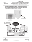
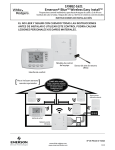
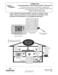
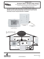
Emerson® Blue™ Wireless Easy Install™
Provides Wireless Control for up to 4 Heat/2 Cool Heat Pump Stages
or up to 2 Heat/2 Cool Stages on Conventional Systems
INSTALLATION INSTRUCTIONS
FAILURE TO READ AND FOLLOW ALL INSTRUCTIONS CAREFULLY
BEFORE INSTALLING OR OPERATING THIS CONTROL COULD CAUSE
PERSONAL INJURY AND/OR PROPERTY DAMAGE.
Equipment Control
Module
Return Air Sensor
(RAS)
Comfort Interface
[
Optional Remote
Sensor(s) not included
[
1F98EZ-1621 will accept
up to 3 remote sensors
1
Model 1F98EZ-1641
Includes Comfort/User
Interface, Equipment Control
and one Wireless Remote Sensor
Remote Sensor
(outdoor location)
Comfort Interface
Equipment Control
Module
PART NO. 37-7235A
www.white-rodgers.com
www.emersonclimate.com
1114
INDEX
)
3
4
5
5
6
7
8
8
10
Mount Return Air Sensor and Equipment Control
Equipment Control Module Wiring to HVAC Equipment
Install Batteries
Installer Quick Reference
Check System Operation
Locate and Mount Comfort Interface
View Wireless Devices
Troubleshooting
APPLICATIONS
'%
(
&
Applications
Single Stage
Gas, Oil, Electric, Heat Only, Cool Only or Heat Cool Systems
1/1
Multi-Stage
Gas, Oil, Electric, Heat Only, Cool Only or Heat Cool Systems
2/2
Heat Pump
Single or Two Compressor Systems with up to 2 Stages of Aux / Em Heat
4/2
Heat Pump with Dual Fuel Single or Two Compressor Systems with up to 2 Stages of Fossil fuel Heat
4/2
SPECIFICATIONS
Electrical Rating:
Input-Hardwire .......................................................
Terminal Load ................................................................
Setpoint Range ..............................................................
Operating Ambient ........................................................
Operating Humidity .......................................................
Shipping Temperature Range .........................................
Dimensions Interface .....................................................
Dimensions Control .......................................................
20 to 30 VAC
1.0A per terminal, 2.5A maximum all terminals combined
45° to 99°F (7° to 37°C)
32°F to +105°F (0° to +41°C)
90% non-condensing max.
-40° to +150°F (-40° to +65°C)
4-1/2”H x 6”W x 1-1/4”D
5-1/2”H x 5-3/4”W x 1-1/2”D
! CAUTION
! " #
$$%
!
WARNING
2
ATTENTION: MERCURY NOTICE
This product does not contain mercury. However, this product
may replace a product that contains mercury.
Mercury and products containing mercury must not be
discarded in household trash. Do not touch any spilled
mercury. Wearing non-absorbent gloves, clean up any spilled
mercury and place in a sealed container. For proper disposal of
a product containing mercury or a sealed container of spilled
mercury, place it in a suitable shipping container. Refer to
for location to send product
containing mercury.
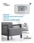
MOUNT RETURN AIR SENSOR AND EQUIPMENT CONTROL
IMPORTANT
-
$
0
1
3
Return Air
(043(1
The RAS monitors temperature of the return air and is needed at
all times for system operation.
Mount Equipment Control Module on wall near HVAC equipment,
or on the air handler. Do not install Equipment Control Module
inside of the HVAC equipment. Use screws to securely fasten
control in place. Do not drill into critical furnace components. Wall
anchors and screws are provided for dry wall mounting (3/16”).
See next page for wiring.
Drill 1/4” hole in return air duct at least 18” upstream from
Insert RAS into duct and fasten with two sheet metal screws.
If the system is hydronic, locate return air sensor in conditioned
space.
5(
1. Remove the cover from the Equipment Control Module.
2. Plug Return Air Sensor (RAS) lead into return air sensor
connection on the Equipment Control Module 0"
1.
Route the sensor lead into the wiring channel and out the top
of the control.
3. Use thermostat wire to make the connections from Equipment
Control Module to the HVAC equipment or terminal strip. Strip
the sheath of the wire bundle back approximately 10”.
Return Air Duct
Supply
Duct
Return
Air Sensor
(Required)
4. Insert wire bundle into the bottom of Equipment Control
Module. Two slots are provided if more than one bundle of wire
are required.
5. Route two wires from the bundle to the left side of the
Equipment Control Module for terminals R and C.
6. Route the rest of the wires in the bundle to the right side of the
Equipment Control Module and fasten loosely with wire ties.
7. Trim wires to length for each connection required, strip ends
and insert into control quick connect block.
Refer to wiring diagram for terminal functions and wire routing.
Equipment Control
Module
To Return Air Sensor (RAS) Required
Wire Tie
Note: Ten (10) feet of wire is supplied with the RAS.
DHM
DHM2
Connect
SYS
Wire Tie
HM2 HM
W/E
W2
Y
Y2
G
O/B
L
R
C
to terminal
connections on
HVAC equipment
DRY
HM
HM2
SYS
C
R
RC
RH
C
DRY
R
RC
DHM2 DHM
POWER
R and C
from HVAC
Terminal Strip
or System
Transformer
W/E
W2
Y
Y2
G
O/B
L
SYSTEM L
LED On/Off
HM
HM2
DHM
DHM2
"'
3
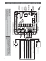
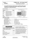
EQUIPMENT CONTROL WIRING TO HVAC EQUIPMENT
Status/Fault
7-Segment LED
Return Air Duct
Sensor Socket
R and C
from HVAC
Terminal Strip
or System
Transformer
Status LED
Connect Push
Button Switch
Return Air Sensor (RAS) Required
RC
R
RC
RH
C
Connect
LED Push
Button Switch
LED On/Off
W/E
W2
Y
Y2
G
O/B
L
HM
HM2
DHM
DHM2
W/E
Y
W2
G
Y2
O/B
**HM Switch **DHM Switch
**To use the HVAC transformer to power humidification/dehumidification switch HM/DHM
switches to “SYS” position:
- Connect humidifier to HM
- Connect dehumidifier to DHM
If humidifier or dehumidifier has a separate transformer switch HM or DHM switch to “DRY” position:
- Connect humidifier to HM and HM2 (or)
- Connect dehumidifier to DHM and DHM2
Y
Y2
O/B
C
(if Heat Pump)
Outdoor Condenser
(A/C or Heat Pump)
Stage 1 - Outdoor Condenser (Conventional or HP)
Stage 2 - Outdoor Condenser (Conventional or HP)
Fan Relay
Changeover Relay Heat Pump
Comfort Alert Connection
24 VAC Transformer Hot
24 VAC Transformer Neutral
Indoor Air Handler/Furnace Connections
W/E
W2
Y
Y2
G
O/B
L
R
C
Dehumidification Relay / Connection
Dehumidification Relay / Connection (for dry contacts)
120 VAC
Humidification Relay / Connection
Humidification Relay / Connection (for dry contacts)
Heat Stage 1 - Indoor Unit or Furnace (Conventional Gas, Oil, Elec) or HP 1 Stage Aux/Em
Heat Stage 2 - Indoor Unit or Furnace (Conventional Gas, Oil, Elec) or HP 2 Stage Aux/Em
HM
HM2
DHM
DHM2
HOT
24 VAC
NEUTRAL
*HVAC Transformer
* For two transformer system, cut and tape off one transformer. If
transformer safety circuits are only in one of the systems, remove
the transformer of the system with NO safety circuits. If required,
replace remaining transformer with a 75 VA Class II transformer. After
disconnecting one transformer, the two commons must be jumpered
together.
4
SYSTEM L
HM2 HM
DHM2 DHM
DRY
DRY
SYS
SYS
POWER
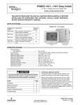
INSTALL BATTERIES
Install batteries in the Comfort Interface.
IMPORTANT
Wireless communication for the Comfort Interface and
!
"
#
the factory. It is not necessary to press the connect buttons at
installation.
+
-
+
-
+
-
+
-
4 “AA” Batteries
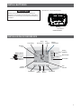
INSTALLER QUICK REFERENCE
Time of Day
Room
Temperature
Day
of Week
Setting
Temperature
Wireless
Icon
Setting
Up/Down
Battery Status
Full charge
Half capacity
Change
= Replace
Batteries
Menu Button
Run Button
Fan
Indicator
System
Indicator
Heat Button
A/C
Button
Fan
Button
OFF Button
5
CONFIGURE COMFORT INTERFACE FOR SYSTEM
9
3
'
On the Home Screen Display, press and hold the Menu button for approximately 5 seconds to enter the Comfort Interface Options
!
$
Menu button again for approximately 5
"
Menu. Press %
#
Menu
4 SS1
Number MS2
-
0;-1
or
Press
to select options
01
MS2
SS1#<)2#<)1
MS2 = Multi-Stage conventional (no heat pump)
HP1 = Single compressor
HP2 = 2 compressor 2 speed compressor
SS1 = Single Stage conventional (no heat pump)
02
0=3(1
ELE
0>1
GAS
Gas setting: Furnace controls blower
Elec setting: Comfort Interface controls blower
03
0&1
On
B
04
<3!&?
<3!3&?#
<;&?#
<&?#3!&?
3%<3!3&?#
3%<;&?#
3%<&?#3!&?
;3#(>
HP1
HP2
3%<3!&?
05
0'1
CR Heat
0'1
CR A/C
0'1
CR Heat A/C
0;31
43%<
0&?1
CA
06
07
08
09
6
;3#(>
;3#(>
SL
On
10
0&?1
-<
On
11
0&?1
ID Hum
On
12
0&?1
CL
On
13
0&?1
CO
On
14
MS2
0&1
FA Heat
&?
15
MS2
0&1
FA A/C
&?
Description
“O” Energizes O/B reversing valve terminal in cooling
“B” Energizes O/B reversing valve terminal in heating
%
1 or MS2
%
$1 or HP2
2
1. If longer cycles are desired, set to SL.
Heat cycle rate: Fast, Med, and Slow
2
1
Cool cycle rate: Fast, Med, and Slow
1
2)
Heat Pump cycle rate: Fast, Med, and Slow
! 1
2)
Auxiliary cycle rate: Fast, Med, and Slow
"
"#$
&Enables active protection for the compressor. If the CA module sends alerts for condition
number #2, 3, 4, 6 or 7 the interface will cancel the call for cool to protect compressor. The
interface will blink setpoint and display “Call for Service” as well as the Comfort Alert numbers.
(see troubleshooting for Comfort Alert)
&;; Will disable the active protection for the compressor
%&
&
#
'
*
OFF
'
+
01
345
past 80%
01
Selecting On energizes the DHM terminal(s) and fan terminal (G) when humidity is above the
6
+
from the heating and cooling system.
Note: 7
"
&
"
'
%
Menu #8)
%
#
'
*
OFF
'*
On
9
!
'*
';*
%
#%
setting. This feature is often used on steam systems and is independent from the call for heat or cool.
Note: 7
"
"
'
%
Menu #7)
'
(
>&Will cause the interface to wait 5 minutes between cooling cycles. This is intended to help
protect the compressor from short cycling. Some newer compressors already have a time delay
built in and do not require this feature. Your compressor manufacturer can tell you if the lockout
feature is already present in their system. When the Comfort Interface compressor time delay
%
>
"
>&;;Will disable the feature
"*
CO ON
6
"
1
When compressor turns on (for a call for heat in heat pump or a call for cool) the fan will be
"
#
%
#
1
%
?@
additional cooling from the system.
&&;; There will be no delay in fan operation
+
ON - Will enable this feature if you need to rapidly heat your home. Manually changing the
setpoint by 3 degrees or more will enable all stages of heat.
OFF - May not bring on secondary rapidly because it allows the Comfort Interface to compute
the optimum time to stage.
+
& Will enable this feature if you need to rapidly cool your home. Manually changing the
setpoint by 3 degrees or more will enable all stages of cool.
&;;May not bring on secondary rapidly because it allows the Comfort Interface to compute
the optimum time to stage.
CHECK SYSTEM OPERATION
<
!-
&
NOTE
"
$ $
$
<@3
Z
Apply power to Equipment Control Module.
Fan Operation
If your system does not have a G terminal connection, skip to
<
(section.
1. Press FAN button. Blower should turn on.
2. Press FAN button. The blower should stop immediately.
3. “
” indicates fan is in auto mode.
<
(
1. Press Heat or A/C button to heat or cool. Run temperature
1o above or below room temperature. The heating or cooling
system should start.
2. For staging systems, run temperature 3o above or below room
temperature. Heat or Cool - LED display will be indicated on
equipment control.
3. Run temperature to below or above room temperature. The
1
1. <!<
!-
+
%
!
#7 and 8.
(
(-
Your Comfort Interface is designed to determine the optimum
time to activate the second stage. Simply raising the temperature
in heating or lowering it in cooling will not always force the
Comfort Interface to bring the second stage on quickly. There is a
@6\@
EXAMPLE: For the last 2 hours the Comfort Interface is set on 70o
and the room temperature is 70o with the equipment using only the
^
within 1o of setpoint, the Comfort Interface will delay the second
stage for a longer time if you manually raise the temperature or
if the room temperature quickly changes. Once the second stage
%
_
1
#%
+
1
%
#
making temperature the second stage will delay longer. When
^
temperature in a reasonable time, the second stage will come on
sooner. This built in function automatically optimizes the use of
additional stages of heat or cool.
"
J&
%
indicate the selections of the Comfort Interface. The following
tables show the LED indications if LED indications are turned on.
Remove Equipment Control Module cover and press the LED switch
"%
J&
$
#
J&
1
W/E
W2
Y
Y2
G
O/B
Conventional
Gas or Elect
Pump
Gas or Elect
Amber
Amber
Amber
Amber
Amber
Amber
Amber
Amber
Green
Green
Green
Green
RH
DRY
Green
Amber
RH
DRY
Green
Amber
HM
W/E
W2
Y
Y2
G
O/B
DHM
"
LED Indicator legend:
= Amber
= Green
01
K
01
HM
DHM
J&X
%
#
%
J&X
%
>
"
W/E – 1st Stage Heating or Auxiliary
W2 – 2nd Stage Heating or Auxiliary
Y – 1st Stage Cooling
Y2 – 2nd Stage Cooling
G – Fan
!
Z
&!
Z
&
7
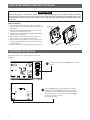
LOCATE AND MOUNT COMFORT INTERFACE
IMPORTANT
9 # )$
0$
1
[@
Wireless Devices (see $1\#
[;
\
?
$"
1. Locate Comfort Interface on interior wall approximately 5
1
"
"
temperature.
2.
$
1
#
`
Interface will cause damage to the unit.
3. Place sub-base on wall and mark mounting hole locations on
wall using base as a template.
4. Move sub-base out of the way. Drill mounting holes. Use
plastic screw anchors if needed to secure the base.
5. Fasten sub-base snugly to wall using two mounting screws.
J"
%
1
Interface operation.
6. Comfort Interface can be attached after checking operation.
Mounting Holes
Sub-base
Comfort Interface
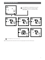
@554>((-@(
Enter wireless set-up menu - checking wireless components
installed.
1
2
8
At Comfort Interface, press the Menu button once and
release
Press the Connect button once and release. The Comfort
Interface will indicate [(\ and then display [>\
(for Equipment Control Module) when communication has
#
%
%
[;
\
or CTL will not appear on screen.
(see Troubleshooting)
@554>((-@(
3
Press the % button once, 4(1 (Remote sensor) should
be displayed if a remote sensor is installed. Press %
'*
4(2,4(3,&4(4
(outdoor), RAS.
Equipment Control
Module (Required)
Remote Sensor 1 (if installed)
Remote Sensor 2 (if installed)
Outdoor Remote Sensor (if installed)
4
Remote Sensor 3 (if installed)
Return Air Sensor (required)
Press the Run button to return to Home screen.
Note: The battery life for each wireless device is shown as it is being displayed on the Comfort Interface display.
9
TROUBLESHOOTING
Reset Operation
If a voltage spike or static discharge blanks out the display or
causes erratic Comfort Interface operation, you can reset it by
removing batteries for 2 minutes. After resetting it, replace the
batteries and reset clock. If it still does not function correctly,
press
and
and Fan button simultaneously. The Comfort
Interface should go blank and then all segments will be displayed
momentarily.
Note: j
"%
{
settings and programming will reset back to factory settings.
Symptom
Possible Cause
Correction Action
Communication Failure
1. Loss of 24 volt power to Equipment
Control Module.
2. Comfort Interface & Equipment Module
are located too far apart.
3. Too much interference between devices.
1. Check 24 volt power at R-C on Equipment Control Module.
Comfort Interface display setting requires
adjustment.
+
#
~
465o. See Temperature Display
~
!
;03
1
Cycles Too Fast or Too Slow
0
1
The location of the Comfort Interface and/
or the size of the heating system may be
>
Digital Comfort Interfaces provide precise control and cycle faster
+
1
frequently but runs for a shorter time so there is no increase in energy
use. If you would like an increased cycle time, choose SL for slow cycle
"
Cooling system requires service.
Verify you are set to cool. Lower the setting below the room
temperature.
;
2. Relocate Comfort Interface closer to the Equipment Control Module.
3. Relocate Comfort Interface away from obstruction or closer to
Equipment Control Module.
Check Easy Install module Y
'*
J&X
>
Interface/Equipment Control Module is calling for cool. Check for
broken or shorted wire from Equipment Control Module to HVAC
Equipment. If LED is OFF or solid ON Comfort Interface not calling.
Check 24 volt power to C - Y, G from Equipment Control Module to
HVAC Equipment.
See fault code table for Comfort Alert Systems.
<0
<)3%1
1. Furnace lock-out condition. Heat may also
be intermittent.
2. Heat pump system requires service.
3. Pilot light not lit.
<#;4
constantly
;]
>
1.
2.
3.
4.
Possible short in wiring.
Possible short in Comfort Interface.
Possible short in heat/cool/fan system.
Fan Switch set to Fan ON.
1. Verify you are set to heat. Raise setpoint above the room
temperature.
^
'*
J&X
>
Interface/module is calling for heat. Check for broken or shorted
wire from module to HVAC Equipment. If LED is &? or solid ON
Comfort Interface not calling.
Check for 24 volt power to C- W/E, W2 from module to HVAC
Equipment.
2. Many furnaces have safety devices that shut down when a lockout condition occurs. If the heat works intermittently, contact the
furnace manufacturer or local HVAC service person for assistance.
See fault code table for Comfort Alert Systems.
3. Re-light pilot.
Check each wire connection from module to HVAC Equipment to
verify they are not shorted or touching together.
^
!
J&X
>
Equipment Control Module is calling for heat, cool or fan. If heat or
cool runs with LED OFF solid ON check for shorted wire from module
to HVAC Equipment.
Press and hold the Menu button for a minimum of 15 seconds. The Comfort
Interface lock icon will be removed and Comfort Interface will return
to normal operation.
Note: For troubleshooting Wireless Remote Temperature Sensors, refer to Installation Instructions for F145RF-1600.
10
TROUBLESHOOTING
4$5-
If the system does not operate or communicate properly using
the previous troubleshooting page, follow the steps below. This
procedure removes and reconnects all wireless devices in the
system to assure communication.
Remove Wireless Devices
1. At the Comfort Interface, press Menu button once.
2. Press the Connect button.
3. Press and release the % button until the display shows the
device you want to delete, CTL, RS 1, RS 2, RS 3 or ORS.
CTL (Equipment Control Module )
RS 1 (Indoor remote sensor 1)
RS 2 (Indoor remote sensor 2)
RS 3 (Indoor remote sensor 3)
ORS (Outdoor remote sensor 4)
RAS (Return Air Sensor - do not delete)
4. Press and hold the
and
buttons simultaneously to
delete each device. Press %until the display shows the
next device to delete.
5. Press the Run button to exit the menu.
3
5-
1. Power the device.
2. Go to "'
and press the Connect
button. " '
J&
%
>
green indicating searching for wireless devices.
3. Press the Connect button on the device you want to add.
5-
1. Using the Comfort Interface, press the Menu button once.
2. Press the Connect button once and release. Comfort Interface
will display (CTL) control and wireless icon.
3. Continue pressing and releasing the % button to view all
connected and communicating wireless devices. They will
appear in the following order to a maximum of:
CTL (Equipment Control Module)
RS 1 (Indoor remote sensor 1)
RS 2 (Indoor remote sensor 2)
RS 3 (Indoor remote sensor 3)
ORS (Outdoor remote sensor 4)
RAS (Return Air Sensor)
11
TROUBLESHOOTING
Note: This is only applicable for systems featuring 3 (or similar) technology.
3TM $
"
3 '
'
7(>-
Status LED
Description
Comments
=[)&54\
Module has power
4
[4)\;
1. Compressor protector is open. Check high head pressure and compressor supply
voltage.
2. Check for open unit power disconnect, circuit breaker or fuses, low pressure switch
if present in system or Compressor contact or has failed open.
3. Broken wire or connector not making contact.
1. Low refrigerant charge.
2. Evaporator blower is not running. Check blower relay, blower motor capacitor,
motor failure or blockage, wiring and connectors, blower control board, Comfort
Interface wiring for open circuit.
3. Evaporator coil is frozen. Check for low suction pressure, low Comfort Interface
"
>%
'#^
%^
*
4.
'
#^
*
5. Check Comfort Interface sub-base or wiring for short circuit, Comfort Interface
installation (location, level)
6. Faulty TXV (Thermostatic Expansion Valve). Check TXV bulb installation (size,
*
+_
^
"
System Pressure Trip
1. High head pressure. Check high pressure switch if present in system, overcharge
Discharge or suction
with refrigerant, non-condensable in system.
pressure out of limits or 2. Condenser coil poor air circulation (dirty, blocked, damaged)
compressor overloaded 3. Condenser fan not running. Check fan capacitor, wiring and connectors, motor for
failure or blockage.
4. Return air duct has substantial leakage
5. If low pressure switch present in system, check Flash Code 1 information.
Short Cycling
1. Comfort Interface demand signal is intermittent
Compressor is running 2. Time delay or control board defective
#>
3. If high pressure switch present go to Flash Code 2 information
4. If low pressure switch present go to Flash Code 1 information
Locked Rotor
1. Run capacitor has failed.
2. Low line voltage (contact utility if voltage at disconnect is low) check wiring.
3. Excessive liquid refrigerant in compressor. Compressor bearings are seized,
measure compressor oil level.
Open Circuit
1. Open Outdoor unit power disconnect, circuit breaker, fuse(s). Compressor
contactor failed to open. Check wiring on compressor contactor and between
supply and compressor, contactor failure (burned, pitted), low pilot voltage at
compressor contactor coil.
2. High pressure switch is open and requires manual reset.
3. Unusually long compressor protector reset time due to extreme ambient
temperature.
4. Compressor windings are damaged. Check compressor motor winding resistance.
Open Start Circuit
1. Run capacitor has failed.
Current only in run
2. Open circuit in compressor start wiring or connections. Check wiring and
circuit
connectors between supply and the compressor “S” terminal.
3. Compressor start winding is damaged. Check compressor motor winding resistance.
Open Run Circuit
1. Open circuit in compressor run wiring or connections. Check wiring and connectors
Current only in start
between supply and the compressor “R” terminal.
circuit
2. Compressor run winding is damaged. Check compressor motor winding resistance.
Welded Contactor
1. Compressor contactor has failed closed
Compressor always runs 2. Comfort Interface demand signal not connected to module
Low Voltage Control
1. Control circuit transformer is overloaded
Circuit < 17 VAC
2. Low line voltage (contact utility if voltage at disconnect is low). Check wiring
connections
Control circuit voltage
too low for operation
^[3>4\
;1
1
^[3>4\
;2
2
^[3>4\
;3
3
^[3>4\
;4
4
^[3>4\
;5
5
^[3>4\
; 6
6
^[3>4\
;7
7
^[3>4\
; 8
^[3>4\
;9
8
9
Supply voltage is present at module terminals
Comfort Interface energizing “Y” terminal
to call for cool but the
compressor is not running
Long Run Time
Compressor is running
extremely long run
cycles
4
;
^3;
0
!
>
#
#
J&
>
%
#
White-Rodgers is a division
of Emerson Electric Co.
The Emerson logo is a
trademark and service mark
of Emerson Electric Co.
www.emersonclimate.com