1
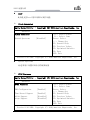
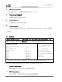
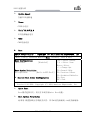
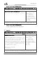
特种计算机 Industrial Computer 产品说明书 User Manual EC3-1816CLD2NA(B) Cedar Trail + NM10 3.5 寸主板 Cedar Trail+NM10 3.5-inch Motherboard Version:C01 法律资讯 警告提示 为了您的人身安全以及避免财产损失,必须注意本手册中的提示。人身安全 的提示用一个警告三角表示,仅与财产损失有关的提示不带警告三角。警告提示 根据危险等级由高到低如下表示。 危险 表示如果不采取相应的小心措施,将会导致死亡或者严重的人身伤害。 警告 表示如果不采取相应的小心措施,可能导致死亡或者严重的人身伤害。 小心 带有警告三角,表示如果不采取相应的小心措施,可能导致轻微的人身伤害。 注意 表示如果不注意相应的提示,可能会出现不希望的结果或状态。 合格的专业人员 本文件所属的产品/系统只允许由符合各项工作要求的合格人员进行操作。 其操作必须遵照各自附带的文件说明,特别是其中的安全及警告提示。 由于具 备相关培训及经验,合格人员可以察觉本产品/系统的风险,并避免可能的危险。 EVOC产品 请注意下列说明: 警告 EVOC产品只允许用于目录和相关技术文件中规定的使用情况。如果要使用其他 公司的产品和组件,必须得到EVOC推荐和允许。正确的运输、储存、组装、装 配、安装、调试、操作和维护是产品安全、正常运行的前提。必须保证允许的环 境条件。必须注意相关文件中的提示。 免责声明 本公司保留对此手册更改的权利,产品后续相关变更时,恕不另行通知。 对于任何因安装、使用不当而导致的直接、间接、有意或无意的损坏及隐患概不 负责。 订购产品前,请向经销商详细了解产品性能是否符合您的需求。 EVOC是研祥智能科技股份有限公司的注册商标。本手册所涉及到的其他商 标,其所有权为相应的产品厂家所拥有。 研祥智能科技股份有限公司©2014,版权所有,违者必究。未经许可,不得 以机械、电子或其它任何方式进行复制。 保修条款: 产品保修期一年。用户如另有要求,以双方签署的合同为准。 欲获更多信息请访问: 研祥网站:http://www.evoc.com 研祥技术支持邮箱:[email protected](国际) 、[email protected](国内) 免费客服热线: 4008809666 文档说明 本文档适用范围 本文档适用于EVOC EC3-1816CLD2NA(B)型号。 约定 在本文档中,术语“本板”或“产品”有时特指EVOC EC3-1816CLD2NA(B) 产品。 说明 安全相关注意事项 为避免财产损失以及出于个人安全方面的原因,请注意本入门指南中关于安 全方面的信息。 文中使用警告三角来指示这些安全信息,警告三角的出现 取决于潜在危险的程度。 目录 1. 产品介绍 .................................................................................................................1 1.1 简介 ...............................................................................................................1 1.2 机械尺寸、重量与环境................................................................................1 1.3 典型功耗 .......................................................................................................2 1.4 微处理器 .......................................................................................................2 1.5 芯片组 ...........................................................................................................2 1.6 系统内存 .......................................................................................................2 1.7 显示功能 .......................................................................................................2 1.8 网络功能 .......................................................................................................2 1.9 音频功能 .......................................................................................................3 1.10 电源特性 .....................................................................................................3 1.11 Watchdog功能 ..............................................................................................3 1.12 操作系统 ......................................................................................................3 1.13 I/O接口.........................................................................................................3 2.安装说明 ...................................................................................................................4 2.1 产品外形尺寸图 ............................................................................................4 2.2 接口位置示意图 ...........................................................................................5 2.3 架构图 ...........................................................................................................6 2.4 跳线设置 .......................................................................................................7 2.5 串口 ................................................................................................................8 2.6 LCD背光控制接口 ........................................................................................9 2.7 显示接口 ........................................................................................................9 2.8 USB接口 ...................................................................................................... 11 2.9 网络接口 ......................................................................................................12 2.10 音频接口 ....................................................................................................13 2.11 鼠标键盘接口 ............................................................................................13 2.12 SATA接口...................................................................................................13 2.13 SATA硬盘热插拔.......................................................................................14 2.14 GPIO接口...................................................................................................15 2.15 风扇接口 ....................................................................................................15 2.16 电源接口 ....................................................................................................16 2.17 状态指示控制接口 ....................................................................................17 2.18 MSATA接口 ...............................................................................................18 2.19 CF卡(可选) ...........................................................................................19 3. BIOS功能介绍 .......................................................................................................20 3.1 UEFI简介 .....................................................................................................20 3.2 UEFI参数设置 .............................................................................................20 3.3 UEFI基本功能设置 .....................................................................................21 3.4 x86 平台下UEFI所要管理的系统资源 .......................................................34 4.驱动程序安装说明 .................................................................................................37 5.附录.........................................................................................................................38 5.1 BPI功能介绍 ................................................................................................38 5.2 常见故障分析与解决 ..................................................................................39 产品介绍 1.产品介绍 1.1 简介 本板采用Intel® Atom™D2550/N2600 + NM10芯片组(EC3-1816CLD2NA(B)-DW 采用Intel® Atom™ D2550 + NM10芯片组,EC3-1816CLD2NA(B)-N2600采用Intel® Atom™ N2600 + NM10芯片组);其中D2550为1M Cache 1.86GHz,N2600为1M Cache 1.6GHz;支持板载2GB DDR3 内存(EC3-1816CLD2NA(B)-DW的主板板载1066MHz 的2GB内存, EC3-1816CLD2NA(B)-N2600的主板板载800MHz的2GB内存);显示支 持VGA、LVDS,支持单显或双显。板载2个10/100/1000Mbps网络接口。 本板具有丰富的外围接口,支持1个SATA接口,1个MSATA接口(可选)和1 个CF卡(可选),MSATA和CF不可同时使用,选择方式可在BIOS SETUP里面设置; 6个USB 2.0接口、4个串口(其中COM1支持RS-232/RS-485);1个标准的 MIC-IN/LINE-IN/LINE-OUT音频接口。 1.2 机械尺寸、重量与环境 外形尺寸(带散热器): EC3-1816CLD2NA(B)-DW:146.1mm(长)×101.6mm(宽)×28mm(高) EC3-1816CLD2NA(B)-N2600:146.1mm(长)×101.6mm(宽)×33mm(高) 净重:0.19Kg; 工作环境: EC3-1816CLD2NA(B)-DW 支持: 工作温度:0℃~60℃,可扩展温度:-40℃~80℃ 湿度:5 %~95%(非凝结状态) EC3-1816CLD2NA(B)-N2600 支持: 工作温度:0℃~60℃,可扩展温度:-40℃~85℃ 湿度:5%~95%(非凝结状态) 贮存环境: 温度:-40℃~80℃ 湿度:5%~95%(非凝结状态) EC3-1816CLD2NA(B) - 1 - 产品介绍 1.3 典型功耗 典型功耗是基于以下配置闲置状态的数值。 EC3-1816CLD2NA(B)-DW CPU:板载 Intel® Atom ™ CPU D2550 @ 1.86GHz 内存:板载 Samsung/DDRIII 1066/2G [email protected];+5%/-3%; EC3-1816CLD2NA(B)-N2600 CPU: 板载 Intel® Atom ™ CPU N2600 @ 1.60GHz 内存:板载 Samsung/DDRIII 1066/2G [email protected];+5%/-3%; 1.4 微处理器 板载Intel® Atom™ D2550(双核)1M Cache 1.86GHz/N2600(双核)1M Cache 1.6GHz处理器。封装为Micro-FCBGA11。 1.5 芯片组 Intel® ATOM™ D2550/N2600 + NM10 1.6 系统内存 板 载 2GB DDR3 内 存 , EC3-1816CLD2NA(B)-DW 内 存 支 持 1066MHz , EC3-1816CLD2NA(B)-N2600 内存支持 800MHz。 1.7 显示功能 支持VGA、LVDS显示, VGA支持热插拔功能;都为同步输出; VGA支持最高分辨率及刷新率为1920×1200@60Hz,LVDS最大支持1920× 1080@60HZ。 1.8 网络功能 提供2个10/100/1000Mbps网络接口,LAN1可支持网络唤醒功能。 - 2 - EC3-1816CLD2NA(B) 产品介绍 1.9 音频功能 采用HDA标准,支持 MIC-IN/LINE-IN/LINE-OUT。 1.10 电源特性 采用单12V供电。 注:默认模拟ATX电源开关机,如需采用AT开机模式,请参看说明书2.4.2部分, 做相应的跳线设置。 1.11 Watchdog功能 支持 255 级,可编程按分或秒; 支持看门狗超时中断或复位系统。 1.12 操作系统 支持操作系统:WINCE/WINXP/WINXPE/WIN7/Linux 1.13 I/O接口 提供 4 个串口,其中 COM1 支持 RS-232/RS-485 模式选择; 支持 1 个 SATA 接口,1 个 MSATA 接口(可选)或者 1 个 CF 卡接口(可选)。 (通过 BIOS 中的“Advanced”-“SATA”—“SATA port Mode as”,在这 里选择 MSATA 或者 CF 卡) ; 提供 6 个 USB2.0 接口; 提供 1 个 PS/2 键盘/鼠标接口; 提供 1 个 8 路数字 I/O 接口。 提示:如何识别跳线、接口第一脚 1、观察插头、插座旁边的文字标记,通常用“1”或加粗的线条或三角符号表示。 2、看看背面的焊盘,通常方型焊盘为第一脚。 EC3-1816CLD2NA(B) - 3 - 安装说明 2.安装说明 2.1 产品外形尺寸图 146.1 130 102 5 8. 4.3 12.5 12.4 25 25 8.7 1.6 4.1 6.5 14.1 15.5 12.6 6.3 39 22 5.1 65 146.1 137.2 101.6 98.4 3.2 3.2 单位:mm 警告! 请务必选择合适的螺钉和使用正确的安装方法(包括板卡定位、CPU、散热 器等安装),否则可能损坏板。此板推荐 H1~H4 使用 M3×6 GB9074.4-88 螺钉。 - 4 - EC3-1816CLD2NA(B) 安装说明 2.2 接口位置示意图 在板背面 在板背面 EC3-1816CLD2NA(B) - 5 - 安装说明 2.3 架构图 EC3-1816CLD2NA (B) Function Block Diagram VGA DB15 D2550/ N2600 CPU CH A DP to LVDS Onbord DDR3 DDI1 DMI SATA II (1*7) SATA to CF SATA1 SATA2 PCI-E Port1 82583 LAN1 RJ45 Connector PCI-E Port 2 82583 LAN2 RJ45 Connector NM10 MSATA1 USB 2.0 X6 HDA ALC892 SPI SPI Flash LPC USB SIO W83627UHG LPT - 6 - GPIO COM*4 PS/2 (K/M) WDT FAN EC3-1816CLD2NA(B) 安装说明 提示:如何识别跳线、接口第一脚 1、观察插头、插座旁边的文字标记,通常用“1”或加粗的线条或三角符号表示。 2、看看背面的焊盘,通常方型焊盘为第一脚。 2.4 跳线设置 1. JCC1:CMOS内容清除/保持设置(脚距:2.0mm) CMOS由板上钮扣电池供电。清CMOS会导致永久性消除以前系统配置并将其设 为原始(工厂设置)系统设置。其步骤:(1)关闭计算机,断开电源;(2)瞬间短 接JCC1插针;(3)开计算机;(4)启动时按屏幕提示按键进入BIOS设置,重新加载 最优缺省值;(5)保存并退出设置。设置方式如下: JCC1 2. 设置 功能 1-2 开路 正常工作状态(Default) 1-2 短路 清除 CMOS 内容,所有 BIOS 设置恢复成出厂值 JP1:AT/ATX开机模式选择(脚距:2.0mm) JP1 3. 设置 功能 1-2 短路 AT 开机模式 2-3 短路 ATX 开机模式(Default) JP2~JP3:COM1 RS-232/ RS-485模式选择(脚距:2.0mm) COM1支持RS-232/RS-485两种工作模式,通过跳线JP2/JP3来实现工作模式的 选择。 模式选择 管脚设置 JP2、JP3 RS-232 (Default) RS-485 JP2 1-2 3-4 JP3 1-3 2-4 3-5 4-6 EC3-1816CLD2NA(B) - 7 - 安装说明 4. JCF1:CF卡工作电压选择(脚距:2.0mm) JCF1 5. 设置 功能 1-2 短路 +3.3V 2-3 短路 +5V(Default) JLCD1:LCD工作电压选择(脚距:2.0mm) 不同的 LCD 屏电压可能不同,本板提供了 3.3V 和 5V 两种电压选择,当所 选择的 LCD 电压与所使用的 LCD 屏的工作电压一致时,LCD 屏才能正常显示。设 置方式如下: 设置 JLCD1 功能 1-2 短路 +3.3V(Default) 2-3 短路 +5V 2.5 串口 1、 本板卡提供1个DB9串口,COM1支持RS-232/RS-485。 信号名称 管脚 COM1 RS-232 RS-485 1 DCD# Data- 2 RXD Data+ 3 TXD NC 4 DTR# NC 5 GND GND 6 DSR# NC 7 RTS# NC 8 CTS# NC 9 RI# NC 注:在 RS485 模式下,数据收发方向为自动控制。 - 8 - EC3-1816CLD2NA(B) 安装说明 2、 本主板提供3个2×5Pin的插针串口(脚距:2.0mm),管脚定义如下: 管脚 信号名称 管脚 信号名称 1 DCD# 2 RXD 3 TXD 4 DTR# 5 GND 6 DSR# 7 RTS# 8 CTS# 9 RI# 10 NA COM2~COM4 2.6 LCD背光控制接口 本板提供1个1×4Pin 的wafer LCD背光控制接口(脚距:2.0mm),管脚定 义如下: LCDB1 管脚 信号名称 1 VCC_LCDBKLT 2 LCD_BKLTCTL 3 LCD_BKLTEN 4 GND 注:VCC_LCDBKLT—— +12V 背光电源(电流限制在 1A 以下); LCD_BKLTCTL——背光控制(该信号由 CPU 直接输出,为 PWM 信号,电压幅 值 0V—3.3V,占空比在 0%~100%之间); LCD_BKLTEN ——背光使能,高有效(此板该信号由 CPU 直接输出,CMOS 输 出,电压幅值为 0V-3.3V)。 2.7 显示接口 1、 本主板提供1个标准DB15 VGA接口,管脚定义如下: EC3-1816CLD2NA(B) - 9 - 安装说明 VGA1 管脚 信号名称 管脚 信号名称 1 Red 2 Green 3 Blue 4 NC 5 GND 6 GND 7 GND 8 GND 9 NC 10 GND 11 NC 12 DDCDATA 13 HSYNC 14 VSYNC 15 DDCCLK 注意:由于Intel GMA驱动限制,在安装完显卡驱动后重启进入系统,CRT可能会 成为扩展模式或者CRT不显示(此时CRT为副显),此时可通过Ctrl+Alt+F1热键 进行切换,将CRT转换为主显示。 2、 LVDS接口 本板提供1个双通道24bitLVDS接口(LVDS1、LVDS2;脚距:1.0mm),使用 单通道的18位/24位的LVDS屏时,LVDS数据线要接在LVDS1位置。双通道24位LVDS 管脚定义如下: LVDS1 - 10 - 管脚 信号名称 管脚 信号名称 1 LVDSO_D0+ 2 LVDSO_D0- 3 GND 4 GND 5 LVDSO_D1+ 6 LVDSO_D1- 7 GND 8 GND 9 LVDSO_D2+ 10 LVDSO_D2- 11 GND 12 GND 13 LVDSO_CLK+ 14 LVDSO_CLK- 15 GND 16 GND 17 LVDSO_D3+ 18 LVDSO_D3- 19 VDD 20 VDD EC3-1816CLD2NA(B) 安装说明 管脚 信号名称 管脚 信号名称 1 LVDSE_D0+ 2 LVDSE_D0- 3 GND 4 GND 5 LVDSE_D1+ 6 LVDSE_D1- 7 GND 8 GND 9 LVDSE_D2+ 10 LVDSE_D2- 11 GND 12 GND 13 LVDSE_CLK+ 14 LVDSE_CLK- 15 GND 16 GND 17 LVDSE_D3+ 18 LVDSE_D3- 19 VDD 20 VDD LVDS2 注:LVDSOx表示双扫描PANEL的奇数行,LVDSEx表示双扫描PANEL的偶数行。本板 用到LVDS插座型号为DF20G-20DP-1V,建议使用对应端子的型号DF20A-20DF-1C。 2.8 USB接口 本板提供1组双USB接口连接器(J1)和2组2×5Pin插针USB接口(J2,J3, 脚距:2.0mm),共可支持6个USB设备。 J1(USB1\ USB2) J2、J3 管脚 信号名称 1 +5V 2 USB_Data- 3 USB_Data+ 4 GND 管脚 信号名称 管脚 信号名称 1 +5V 2 +5V 3 USB1_Data- 4 USB2_Data- 5 USB1_Data+ 6 USB2_Data+ 7 GND 8 GND 9 NA 10 GND EC3-1816CLD2NA(B) - 11 - 安装说明 2.9 网络接口 本板提供2个10/100/1000Mbps网络接口,1个是RJ45连接器LAN1,另1个是2 ×7的插针接口(LAN2 脚距:2.0mm)。 LAN1 LILED 网络速度 (双色:黄绿双色) 指示状态 绿色 1000Mbps 有数据传输 橙色 100Mbps 无数据传输 灭 10Mbps ACTLED 网络活动 (单色:绿色灯) 指示状态 闪烁 灭 注:千兆网卡不管有/无Link信号,左边的ACTLED灯表示的是有无数据传输,有 数据传输时,左边的绿色灯应为“闪烁”状态,只连接网络未收发数据时,绿色 灯应为“熄灭”状态,有广播包时,ACTLED灯“闪烁”属于正常。 LAN2 - 12 - 管脚 信号名称 管脚 信号名称 1 MX0+ 2 MX0- 3 MX1+ 4 MX1- 5 MX2+ 6 MX2- 7 MX3+ 8 MX3- 9 GND 10 GND 11 LINK1000- 12 LINK100- 13 ACT_LED+ 14 ACT_LED- EC3-1816CLD2NA(B) 安装说明 2.10 音频接口 本板提供1个2×5Pin的音频接口(脚距:2.0mm)。 管脚 信号名称 管脚 信号名称 1 LOUT_R 2 LOUT_L 3 GND_AUDIO 4 GND_AUDIO 5 LIN_R 6 LIN_L 7 GND_AUDIO 8 GND_AUDIO 9 MIC_L 10 MIC_R AUDIO1 2.11 鼠标键盘接口 本板提供1个Mini DIN一转二的PS/2接口。 KM1 管脚 信号名称 1 KB_DATA 2 MS_DATA 3 GND 4 +5V 5 KB_CLK 6 MS_CLK 2.12 SATA接口 本主板提供1个SATA接口,1个MSATA接口(可选),选择方式可在BIOS SETUP 里面设置,详见BIOS功能介绍。 管脚 SATA1 信号名称 1 GND 2 SATA_TX+ 3 SATA_TX- 4 GND 5 SATA_RX- 6 SATA_RX+ 7 GND EC3-1816CLD2NA(B) - 13 - 安装说明 2.13 SATA硬盘热插拔 SATA 硬盘热插拔需注意: (1) 硬盘必须支持:SATA 2.0 接口,并且采用 15 芯 SATA 硬盘电源接口。 (2) 芯片组驱动程序支持 SATA 硬盘的热插拔。 (3) 不能对操作系统所在的 SATA 硬盘进行带电热插拔。 SATA 硬盘数据线 SATA 硬盘电源线 请按照如下步骤进行 SATA 硬盘热插拔,否则,操作不当会导致硬盘损坏和 数据丢失。 热插入SATA硬盘步骤: 步骤1:请将SATA电源线1x4-针脚(白色)一端接到电源适配器的1x4-针脚电源线 一端。 步骤2:将SATA 数据线接到主板上的SATA接口。 - 14 - EC3-1816CLD2NA(B) 安装说明 步骤3:将SATA电源线15-针脚接口(黑色)一端接到SATA硬盘。 步骤4:将SATA数据线接到SATA硬盘。 热拔出SATA硬盘步骤: 步骤 1:从设备管理器中卸载该硬盘。 步骤 2:从 SATA 硬盘一侧拔去 SATA 数据线。 步骤 3:从 SATA 硬盘一侧拔去 SATA 15-针脚电源线接口(黑色)。 2.14 GPIO 接口 GPIO1 (脚距:2.0mm) 管脚 信号名称 管脚 信号名称 1 GPIO1 2 GPIO5 3 GPIO2 4 GPIO6 5 GPIO3 6 GPIO7 7 GPIO4 8 GPIO8 9 GND 10 NC 注:GPIO Default值为TTL输入/输出,输入输出信号的电压范围为0~5V,1、3、 5、7脚为输入,2、4、6、8脚为输出,出厂默认状态为高5V。 EC3-1816CLD2NA(B) - 15 - 安装说明 2.15 风扇接口 本主板提供 1 个 1×4Pin 的 CPU 风扇接口(CPUFAN1,脚距:2.54mm)。使 用风扇插座时要注意以下三点: 风扇电流不大于 500 毫安(12 伏特)。 请确认风扇接线和本插座的接线是否相符。电源线(通常为红色)在 中间位置。另外就是地线(通常为黑色)和风扇转速输出脉冲信号线 (其它颜色)。有些风扇没有转速检测,但该引线却有高达 12V 的输 出,会损坏主板,这是非标准接线。建议使用带转速检测风扇。 将风扇气流调整成能将热量排出的方向。 CPUFAN1 管脚 信号名称 1 GND 2 +12V 3 FAN_IO 4 FAN_PWM 注:FAN_IO:风扇转速脉冲输出,FAN_PWM:风扇转速PWM控制。 2.16 电源接口 1、AT电源接口,单12V电源接口(脚距:4.2mm) PWR1 - 16 - 管脚 信号名称 1 GND 2 GND 3 +12V 4 +12V EC3-1816CLD2NA(B) 安装说明 2、SATA电源转接接口 wafer 1x4P电源插座( 白色,脚距:2.54mm) PWR2 管脚 信号名称 1 +12V 2 GND 3 GND 4 +5V 2.17 状态指示控制接口 1、电源开关及硬盘指示灯接口(脚距:2.54mm) FP1 管脚 信号名称 管脚 信号名称 1 PWRBTN# 2 GND 3 GND 4 RESET# 5 HDD_LED- 6 HDD_LED+ 2、电源指示灯接口(脚距:2.54mm) FP2 管脚 信号名称 1 PWR_LED+ 2 NC 3 GND 3、扬声器输出接口(脚距:2.54mm) FP3 管脚 信号名称 1 SPEAKER 2 NC 3 GND 4 +5V EC3-1816CLD2NA(B) - 17 - 安装说明 2.18 MSATA接口 MSATA1(在板背面) - 18 - 管脚 信号名称 管脚 信号名称 1 WAKE# 2 +3.3V 3 NC 4 GND 5 NC 6 +1.5V 7 CLKREQ# 8 NC 9 GND 10 NC 11 NC 12 NC 13 NC 14 NC 15 GND 16 NC 17 NC 18 GND 19 NC 20 W_DISABLE# 21 GND 22 23 SATA_RX+ 24 +3.3V 25 SATA_RX- 26 GND 27 GND 28 +1.5V 29 GND 30 NC 31 SATA_TX- 32 NC 33 SATA_TX+ 34 GND 35 GND 36 NC 37 GND 38 NC 39 +3.3V 40 GND 41 +3.3V 42 NC 43 GND 44 NC 45 NC 46 NC 47 NC 48 +1.5V 49 NC 50 GND 51 Reserved 52 +3.3V EC3-1816CLD2NA(B) NC 安装说明 2.19 CF卡(可选) 本主板提供CF卡可选,选择方式可通过BIOS SETUP里面设置,详见BIOS功 能介绍。 CF卡是一种快速存储器,体积很小,使用方便,存储量随使用的卡变化, 如128M、256M等。CF卡插入时只能以一个方向插入,板上标识为CF1,在背面。 管脚 信号名称 管脚 信号名称 1 GND 26 CD1# 2 D3 27 D11 3 D4 28 D12 4 D5 29 D13 5 D6 30 D14 6 D7 31 D15 7 CS0# 32 CS1# 8 GND 33 VS1# 9 ATASEL# 34 IOR# 10 GND 35 IOW# 11 GND 36 WE# 12 GND 37 IRQ 13 VCC 38 VCC 14 GND 39 CSEL# 15 GND 40 VS2# 16 GND 41 RESET# 17 GND 42 IORDY 18 A2 43 DREQ 19 A1 44 DACK# 20 A0 45 DASP# 21 D0 46 ATA66_DET 22 D1 47 D8 23 D2 48 D9 24 WP/IOCS16# 49 D10 25 CD2# 50 GND EC3-1816CLD2NA(B) - 19 - BIOS 功能介绍 3.BIOS功能介绍 3.1 UEFI简介 UEFI(Unified Extensible Firmware Interface:标准的可扩展固件接口), 是新一代的计算机固件,用于取代传统的BIOS。UEFI固件存储在主板的闪存存储 器中,主要功能包括:初始化系统硬件,设置各系统部件的工作状态,调整各系 统部件的工作参数,诊断系统各部件的功能并报告故障,给上层软件系统提供硬 件操作控制接口,引导操作系统等。UEFI提供用户一个菜单式的人机接口,方便 用户配置各系统参数设置,控制电源管理模式,调整系统设备的资源分配等。 正确设置UEFI的各项参数,可使系统稳定可靠地工作,同时也能提升系统的 整体性能。不适当的甚至错误的UEFI参数设置,则会使系统工作性能大为降低, 使系统工作不稳定,甚至无法正常工作。 3.2 UEFI参数设置 每当系统接通电源,正常开机后,便可看见进入UEFI设置程序提示的信息。 此时(其它时间无效),按下提示信息所指定的按键(通常为<Del>键或<F2>键) 即可进入UEFI设置程序。 通过UEFI设置程序修改的所有设置值(除了日期、时间)都保存在系统的闪 存存储器中,即使掉电或拔掉主板电池,其内容也不会丢失;而日期、时间则保 存在系统的CMOS存储器中,该CMOS存储器由电池供电,即使切断外部电源,其内 容也不会丢失,除非执行清除CMOS内容的操作。 注意!UEFI的设置直接影响到电脑的性能,设置错误的参数将造成电脑的 损坏,甚至不能开机,请使用UEFI内置缺省值来恢复系统正常运行。 由于本公司不断研发更新UEFI,其设置界面也会略有不同,以下的画面供 您参考,有可能跟您目前所使用的UEFI设置程序不完全相同。 - 20 - EC3-1816CLD2NA(B) BIOS 功能介绍 3.3 UEFI基本功能设置 当SETUP程序启动之后,您可以看到Aptio Setup Utility – Copyright (C) 2012 American Megatrends, Inc.主画面如下: Main Aptio Setup Utility – Copyright (C) 2012 American Megatrends, Inc. Main Config Advanced Monitor Boot Security Save & Exit Set the Date. Use‘Tab’ Motherboard Information to switch between Date Project Name EC3-1816CLD2NA(B) elements. BIOS Version C00 P9173012 Build Date 1/31/2013 10:10:10 →←:Select Screen ↑↓:Select Item Processor Type Enter:Select Intel(R) Atom(TM) CPU N2600 @1.60GHz +/-:Change Opt F1:General Help Memory Frequency 800 MHz(DDR3) F2:Previous Values Total Memory 2048 MB F3:Optimized Defaults Power Type ATX F4:Save ESC:Exit LAN0 MAC 00 90 27 E0 00 51 LAN1 MAC 00 90 27 E0 00 52 System Date [Mon 11/01/2009] System Time [00:47:55] Version 2.16.1226. Copyright (C) 2012,American Megatrends, Inc. System Date 选择此选项,用< + > / < - >来设置目前的日期。以月/日/年的格式来表 示。各项目合理的范围是:Month/月(1-12), Date/日(01-31),Year/年(最大至 2099), Week/星期(Mon.~ Sun.)。 System Time 选择此选项,用< + > / < - >来设置目前的时间。以时/分/秒的格式来表 示。各项目合理的范围是:Hour/时(00-23), Minute/分(00-59),Second/秒 (00-59)。 EC3-1816CLD2NA(B) - 21 - BIOS 功能介绍 Config Aptio Setup Utility – Copyright (C) 2012 American Megatrends, Inc. Main Config Advanced Monitor Boot Security Save & Exit Power Configuration Restore AC Power Loss [Last State] Display Configuration IGFX – Boot Type [CRT] DP-to-LVDS Panel Type [800x600/18/Single] LVDS BackLight Value 128 Fixed Graphics Memory Size [128MB] Audio Configuration Azalia Controller USB Configuration UHCI #1 (ports 0 and 1) UHCI #2 (ports 2 and 3) UHCI #3 (ports 4 and 5) UHCI #4 (ports 6 and 7) USB 2.0(EHCI) Support PCIe Root Port Configruation All PCIe Port Automatic ASPM ASPM L0s ASPM L1 Mini PCIe Slot Automatic ASPM ASPM L0s ASPM L1 LAN Configuration LAN2 Automatic ASPM ASPM L0s ASPM L1 [HD Audio] →←:Select Screen ↑↓:Select Item Enter:Select +/-:Change Opt F1:General Help F2:Previous Values F3:Optimized Defaults F4:Save ESC:Exit [Enabled] [Enabled] [Enabled] [Enabled] [Enabled] [Enabled] [Manual] [Disabled] [Disabled] [Auto] [Manual] [Disabled] [Disabled] [Auto] [Manual] [Disabled] [Disabled] Version 2.16.1226. Copyright (C) 2012,American Megatrends, Inc. Restore AC Power Loss 当 AC 电源断掉又供上后,期望计算机回到哪种状态的设置项。 * - 22 - Power Off EC3-1816CLD2NA(B) BIOS 功能介绍 S5 状态,即供上交流电后还需手动开机。 * Power On S0 状态,即供上交流电后自动开机。 * Last State 回到 S0 还是 S5 状态,依赖于计算机断开 AC 电源时的状态。例如,断 开 AC 电源时计算机处在开机状态(S0 状态),那么当重新给 AC 电源时 计算机将自动开机;当断开 AC 电源时计算机已处在关机状态(S5 状态), 那么重新供给 AC 电源时不自动开机(保持 S5 状态)。 IGFX – Boot Type 设置IGD启动主显示设备 DP-to-LVDS Panel Type 用来选择板载LVDS屏的分辨率 LVDS BackLight Value 用来设置LVDS背光亮度调节 Fixed Grapics Memory Size 设置显存大小 Azalia Controller 此选项用于打开或关闭声卡控制器 UHCI #X (ports X and X) 此选项用于按控制器方式来打开或关闭 USB 2.0(EHCI) Support 此选项用于使能USB2.0 All PCIE Port 此选项打开或关闭所有PCIE port口的设备,包括网口1,网口2,Mini PCIE Slot。 Mini PCIE Slot EC3-1816CLD2NA(B) - 23 - BIOS 功能介绍 此选项用于打开或关闭主板上的Mini PCIe Slot接口。 LAN2 此选项用于打开或关闭主板上的网口2 Automatic ASPM 此选项用于选择自动还是手动配置主板上设备的电源管理功能 ASPM L0s 此选项用于打开或关闭L0s省电功能 ASPM L1 此选项用于打开或关闭L1省电功能 Advanced Aptio Setup Utility – Copyright (C) 2012 American Megatrends, Inc. Main Config Advanced Monitor Boot Security Save & Exit →←:Select Screen ↑↓:Select Item Enter:Select +/-:Change Opt F1:General Help F2:Previous Values F3:Optimized Defaults F4:Save ESC:Exit CPU SATA USB COM PPM Clock Generator EVOC Features Version 2.16.1226. Copyright (C) 2012,American Megatrends, Inc. - 24 - EC3-1816CLD2NA(B) BIOS 功能介绍 CPU Aptio Setup Utility – Copyright (C) 2012 American Megatrends, Inc. Advanced CPU Processor Type Intel(R) Atom(TM) i5 CPU EMT64 Supported Processor Speed 1600 MHz System Bus Speed 400 MHz Ratio Status 16 Actual Ratio 16 System Bus Speed 400 MHz Processor Stepping 30661 Microcode Revision 266 L1 Cache RAM 2x56 k L2 Cache RAM 2x512 k Processor Core Dual Hyper-Threading Supported Hyper-threading →←:Select Screen ↑↓:Select Item Enter:Select +/-:Change Opt F1:General Help F2:Previous Values F3:Optimized Defaults F4:Save ESC:Exit [Enabled] Version 2.16.1226. Copyright (C) 2012,American Megatrends, Inc. 显示CPU的相关信息。注意,CPU的Type, Speed, Core, HT等跟平台所安装的CPU 有关,不同系列的CPU所显示的信息不同。 Hyper-Threading Hyper Threading Technology功能的控制开关 EC3-1816CLD2NA(B) - 25 - BIOS 功能介绍 SATA Aptio Setup Utility – Copyright (C) 2012 American Megatrends, Inc. Advanced SATA Port0 SATA Port1 SATA Controller(S) Configure SATA as SATA Port Mode as HDD Latency Time Not Present Not Present [Enabled] [IDE] [mSATA Device] [Disabled] →←:Select Screen ↑↓:Select Item Enter:Select +/-:Change Opt F1:General Help F2:Previous Values F3:Optimized Defaults F4:Save ESC:Exit Version 2.16.1226. Copyright (C) 2012,American Megatrends, Inc. SATA Port0~1动态侦测主板上有没有接SATA设备,如果对应的Port上有接设备, 则显示该SATA设备的型号。否则,显示Not Present。 SATA Controller(S) SATA控制器用来打开或关闭SATA Port上的设备 Configure SATA as 配置SATA设置的类型:IDE或AHCI SATA Port Mode as 用来选择SATA接口是作为mSATA设备,还是CF卡 HDD Latency Time 用来增加开机阶段硬盘侦测时间 - 26 - EC3-1816CLD2NA(B) BIOS 功能介绍 USB Aptio Setup Utility – Copyright (C) 2012 American Megatrends, Inc. Advanced →←:Select Screen ↑↓:Select Item Enter:Select +/-:Change Opt F1:General Help F2:Previous Values F3:Optimized Defaults F4:Save ESC:Exit USB Configuration USB Devices: 1 Keyboard,1 Mouse, 2 Hubs Legacy USB Support [Enabled] Version 2.16.1226. Copyright (C) 2012,American Megatrends, Inc. Legacy USB Support 此选项用于支持传统的USB设备(键盘,鼠标,存储设备等),当该项设为 Enabled时,即使不支持USB的操作系统如DOS下也能使用USB设备。当设置成 Disabled时,传统设备在不支持USB的操作系统中将不可用。 注意:EFI application下USB仍然可用,如Shell下。 COM Aptio Setup Utility – Copyright (C) 2012 American Megatrends, Inc. Advanced COM Serial Serial Serial Serial Port Port Port Port 0 1 2 3 Configuration Configuration Configuration Configuration →←:Select Screen ↑↓:Select Item Enter:Select +/-:Change Opt F1:General Help F2:Previous Values F3:Optimized Defaults F4:Save ESC:Exit Version 2.16.1226. Copyright (C) 2012,American Megatrends, Inc. EC3-1816CLD2NA(B) - 27 - BIOS 功能介绍 Serial Port 0~3 Configuration Aptio Setup Utility – Copyright (C) 2012 American Megatrends, Inc. Advanced Serial Port 0~3 Configuration Serial Port Device Settings [Enabled] IO=3F8h; IRQ=4; Change Settings [Auto] →←:Select Screen ↑↓:Select Item Enter:Select +/-:Change Opt F1:General Help F2:Previous Values F3:Optimized Defaults F4:Save ESC:Exit Version 2.16.1226. Copyright (C) 2012,American Megatrends, Inc. * Serial Port0~3 此项用于打开或关闭当前串口 * Device Settings 此项用于显示串口当前的资源配置 * Change Settings 此项用于配置串口所用的资源(IO和IRQ) PPM Aptio Setup Utility – Copyright (C) 2012 American Megatrends, Inc. Advanced PPM Configration EIST [Enabled] →←:Select Screen ↑↓:Select Item Enter:Select +/-:Change Opt F1:General Help F2:Previous Values F3:Optimized Defaults F4:Save ESC:Exit Version 2.16.1226. Copyright (C) 2012,American Megatrends, Inc. - 28 - EC3-1816CLD2NA(B) BIOS 功能介绍 EIST 此项是支持Intel的CPU频率可调节功能 Clock Generator Aptio Setup Utility – Copyright (C) 2012 American Megatrends, Inc. Advanced Clock Generator Spread Spectrum [Disabled] →←:Select Screen ↑↓:Select Item Enter:Select +/-:Change Opt F1:General Help F2:Previous Values F3:Optimized Defaults F4:Save ESC:Exit Version 2.16.1226. Copyright (C) 2012,American Megatrends, Inc. Spread Spectrum 此选项用于设置时钟信号的展频功能 EVOC Features Aptio Setup Utility – Copyright (C) 2012 American Megatrends, Inc. Advanced EVOC Features FMI Configuration [Enabled] Time Record Support eDisk Support eLogo Support [Enabled] [Disabled] [Disabled] →←:Select Screen ↑↓:Select Item Enter:Select +/-:Change Opt F1:General Help F2:Previous Values F3:Optimized Defaults F4:Save ESC:Exit Version 2.16.1226. Copyright (C) 2012,American Megatrends, Inc. EC3-1816CLD2NA(B) - 29 - BIOS 功能介绍 FMI Configuration 此项是总开关,用来控制是否支持EVOC Features Time Record Support 此项用来记录主板运行时长 eDisk Support 此项用来打开或关闭虚拟磁盘 eLogo support 此项用来在线更换开机Logo,只有当eDisk Support是enabled时,该功能 才能实现 Monitor Aptio Setup Utility – Copyright (C) 2012 American Megatrends, Inc. Main Config Advanced Monitor Boot Security PC Health Status System Temperature CPU Temperature CpuFan Speed Vcore V3.3 V5.0 V12.0 VBAT : +26 C : +57 C :N/A : +1.152 V : +3.328 V : +5.058 V : +12.091 V : +3.296 V Save & Exit →←:Select Screen ↑↓:Select Item Enter:Select +/-:Change Opt F1:General Help F2:Previous Values F3:Optimized Defaults F4:Save ESC:Exit Version 2.16.1226. Copyright (C) 2012,American Megatrends, Inc. 显示当前所侦测到得硬件的电压,温度,风扇转速等监控信息。 System Temperature 当前系统温度,一般主板上有热敏电阻监测。 CPU Temperature 当前CPU温度。CPU的温度由板上的温度传感器监测。 - 30 - EC3-1816CLD2NA(B) BIOS 功能介绍 CpuFan Speed 当前CPU风扇转速 Vcore CPU核心电压 V3.3/ V5.0/V12.0 开关电源输出电压 VBAT CMOS电池电压 Boot Aptio Setup Utility – Copyright (C) 2012 American Megatrends, Inc. Main Config Advanced Monitor Boot Boot Configuration Quiet Boot Security [Disabled] Boot Option Priorities Boot Option #1 [Built-in EFI Shell] Special Boot Order Configuration Save & Exit →←:Select Screen ↑↓:Select Item Enter:Select +/-:Change Opt F1:General Help F2:Previous Values F3:Optimized Defaults F4:Save ESC:Exit Version 2.16.1226. Copyright (C) 2012,American Megatrends, Inc. Quiet Boot Boot模式选择开关,用于打开或关闭Quiet Boot功能。 Boot Option Priorities 此项用于配置系统引导的优先次序。其中#1优先级最高,#n优先级最低。 EC3-1816CLD2NA(B) - 31 - BIOS 功能介绍 Special Boot Order Configuration Aptio Setup Utility – Copyright (C) 2012 American Megatrends, Inc. Boot Special Boot Order Configuration Special Boot Order Configuration →←:Select Screen ↑↓:Select Item Enter:Select +/-:Change Opt F1:General Help F2:Previous Values F3:Optimized Defaults F4:Save ESC:Exit [Disabled] Version 2.16.1226. Copyright (C) 2012,American Megatrends, Inc. Special Boot Order Configuration 此项用于配置传统设备在BBS中的优先次序 Security Aptio Setup Utility – Copyright (C) 2012 American Megatrends, Inc. Main Config Advanced Monitor Boot Security Password Description If ONLY the Administrator's password is set, then this only limits access to Setup and is only asked for when entering Setup. If ONLY the User's password is set, then this is a power on password and must be entered to boot or enter Setup. In Setup the User will have Administrator rights. Save & Exit →←:Select Screen ↑↓:Select Item Enter:Select +/-:Change Opt F1:General Help F2:Previous Values F3:Optimized Defaults F4:Save ESC:Exit Administrator Password User Password Version 2.16.1226. Copyright (C) 2012,American Megatrends, Inc. - 32 - EC3-1816CLD2NA(B) BIOS 功能介绍 Setup Administrator Password 此项用于设置管理员密码 注:如果只设置管理员密码,则只当进入Setup设置程序时需要 输入管理员密码。 Save & Exit Aptio Setup Utility – Copyright (C) 2012 American Megatrends, Inc. Main Config Advanced Monitor Boot Security Save Changes and Reset Discard Changes and Reset Save & Exit →←:Select Screen ↑↓:Select Item Enter:Select +/-:Change Opt F1:General Help F2:Previous Values F3:Optimized Defaults F4:Save ESC:Exit Version 2.16.1226. Copyright (C) 2012,American Megatrends, Inc. Save Changes and Reset 此项用于保存修改并重启 Discard Changes and Reset 此项用于放弃所作修改并重启 EC3-1816CLD2NA(B) - 33 - BIOS 功能介绍 3.4 x86 平台下UEFI所要管理的系统资源 这里的系统资源我们定义三种:I/O端口地址,IRQ中断号和DMA号。 DMA 级别 功能 DMA0 未分配 DMA1 未分配 DMA2 未分配 DMA3 未分配 DMA4 用于 DMAC 的级联 DMA5 未分配 DMA6 未分配 DMA7 未分配 APIC 高级可编程中断控制器。在现代P4以上级别的主板中,大都支持APIC,可 以提供多于16个中断源,如IRQ16—IRQ23,部分主板如支持PCI-X的主板可以有 多达28个中断源。但要启用该功能必须相应的操作系统支持。 IO端口地址 X86的I/O地址线只设计16条,从0~0FFFFh,I/O地址空间总共有64K,在传 统的ISA接口,只使用到前面的1024个(0000~03FFh),0400h以上的端口为PCI 接口与EISA接口所使用。每一外围设备都会占用一段I/O地址空间。下表给出了 X86平台大致上所要用到的I/O接口列表。 - 34 - EC3-1816CLD2NA(B) BIOS 功能介绍 地 址 设备描述 000h – 001Fh DMA 控制器#1 020h - 021h 可编程中断控制器 040h - 043h 系统计时器 060h - 060h PS/2 标准键盘 064h – 064h PS/2 标准键盘 070h - 071h 系统 CMOS/实时时钟 081h - 091h DMA 控制器 0A0h – 0A1h 可编程中断控制器 0C0h – 0DFh DMA 控制器 0F0h – 0FFh 数据数值处理器 2E8h – 2EFh 通信端口 4 2F8h – 2FFh 通信端口 2 3B0h – 3BBh Intel(R) Graphic Media Accelerator 3C0h – 3DFh Intel(R) Graphic Media Accelerator 3E8h – 3EFh 通信端口 3 3F8h – 3FFh 通信端口 1 4D0h – 4D1h 可编程中断控制器 D00h – FFFFh PCI Bus EC3-1816CLD2NA(B) - 35 - BIOS 功能介绍 IRQ中断分配表 系统共0有15个中断源,有些已被系统设备独占。只有未被独占的中断才可 分配给其它设备使用。ISA设备要求独占使用中断;只有即插即用ISA设备才可由 UEFI或操作系统分配中断。而多个PCI设备可共享同一中断,并由UEFI或操作系 统分配。下表给出了X86平台部分设备的中断分配情况,但没有给出PCI设备所占 用的中断资源。 级别 - 36 - 功能 IRQ0 系统计时器 IRQ1 标准 101/102 键或 Microsoft 键盘 IRQ2 保留 IRQ3 通信端口 2 IRQ4 通信端口 1 IRQ5 保留 IRQ6 保留 IRQ7 通信端口 3 4 IRQ8 系统 CMOS/实时时钟 IRQ9 保留 IRQ10 保留 IRQ11 保留 IRQ12 PS/2 鼠标 IRQ13 数据数值处理器 IRQ14 保留 IRQ15 保留 EC3-1816CLD2NA(B) 驱动程序安装说明 4.驱动程序安装说明 本产品的驱动程序可依据配套光盘内容安装,在此不做介绍。 EC3-1816CLD2NA(B) - 37 - 附录 5.附录 5.1 BPI功能介绍 EVOC BPI(BIOS Programming Interface)是一种跨平台的,易维护的,支 持操作系统保护模式下访问硬件的软件接口规范。本产品的功能是为应用层软件 或驱动提供统一的标准接口,在主板硬件升级时,无需修改应用层软件或驱动, 原来的软件就可在新的平台上正常运行。大大提高产品的开发速度和降低产品的 维护成本。目前 BPI 支持 WDT,GPIO 的配置及 H/W monitor 功能,其测试程序及 库函数等相关文档详见说明书光盘。 BPI 具有如下特点: 1、 平台无关性 使用 BPI 库函数开发的软件,无需做任何修改,就可直接在支持 BPI 功能的新平台上正常运行。 2、 安全性和可靠性高 访问硬件的 BPI 库函数由主板开发商编写,并经过严格测试,可避免 因对系统硬件操作不当,造成系统异常问题。 3、 配置灵活 如 GPIO 配置,通过 BPI 库函数或测试程序,用户可很方便地配置任意 一个 GPIO 功能。 4、 易维护 传统方式的 WDT 及 GPIO 编程与硬件密切相关,测试及调试复杂,且需 要维护不同平台的软件,而使用 BPI 开发的软件,只要维护一套软件 即可。 5、 成本低 用户使用 BPI 开发应用程序,不会增加额外的硬件和软件成本。相反 会大大降低软件开发难度,缩短开发周期,可帮助系统集成商产品快 速上市。 - 38 - EC3-1816CLD2NA(B) 附录 5.2 常见故障分析与解决 常见故障 检查点 1. 请确认电源连接线是否连接正常 2. 请确认所用电源是否满足主板的供电要求 3. 查看CPU是否安装到位,CPU卡扣是否扣好 通电之后不开机 4. 尝试重新插拔内存条 5. 尝试更换内存条 6. 尝试根据主板说明书清除主板CMOS 7. 请确认是否有外接卡,去除外接卡后是否正常 BIOS Setup设置不 能保存 1. 请确认CMOS电池电压是否低于2.8V,如低于2.8V,请更 换新电池,重新设置保存 1. 请确认硬盘电源线、数据线是否连接正常 提示无法找到可引 2. 请确认硬盘是否有物理损坏 导设备 3. 请确认硬盘中是否正常安装操作系统 进入系统过程中蓝 1. 请确认内存条及外接卡是否松动 2. 尝试去掉新安装的硬件,卸载驱动或软件 屏或死机 3. 尝试更换内存 1. 尝试使用第三方软件检查硬盘是否有坏道 进入操作系统缓慢 2. 请确认系统所在分区剩余空间是否过少 3. 请确认 CPU 散热风扇是否正常转动 1. 请确认 CPU 散热风扇是否正常转动 2. 请确认是否误触发工控机复位按钮 系统自动重启 3. 请使用杀毒软件确认系统是否感染病毒 4. 请确认内存条及外接卡是否松动 5. 请确认所用电源带载能力是否足够,可尝试更换电源 EC3-1816CLD2NA(B) - 39 - 附录 无法检测到USB设 1. 请确认 USB 设备是否需要单独供电 2. 请确认 USB 接口是否存在接触不良 备 3. 请确认 BIOS Setup 中 USB 控制器是否打开 1. 请确认 PCI 卡是否需要额外供电 无法检测到PCI卡 2. 请确认 PCI 卡工作所需电压与主板 PCI 提供电压(默认 5V)是否相符 3. 请确认更换 PCI 槽位后能否被识别 1. 依据 ISA 卡手册确定 ISA 卡所使用的资源已经被 BIOS 预 留--大部分主板 BIOS Setup 中有针对 ISA 使用 I/O 或 无法检测到ISA卡 memory 资源的预留选项,ISA 卡所使用的 IRQ 是否在 BIOS Setup 中被 reserved 2. ISA 卡一般在系统下无法直接识别,Windows 系统需在 “控制面板”中选择“添加硬件”进行添加 - 40 - EC3-1816CLD2NA(B) Legal Information Warnings Please pay attention to the tips within the manual so as to avoid personal injury or property losses. The tips for personal injury are indicated in warning triangles while the tips only related to property losses have no warning triangles. The warning tips are listed as follows with the hazardous scale from severe to slight. Danger If handled carelessly, death or severe human injury will occur. Warning If handled carelessly, death or severe human injury might occur. Caution Warning triangle indicates that slight human injury might occur if handled carelessly. Note Unexpected result or status might occur, if not handled according to the tips. Professional Personnel The product/system covered by the manual can only be handled by qualified and professional personnel. During operation, please follow the respective instructive manuals, especially the safety warnings. The professional personnel have been trained and possess relevant experiences; therefore, he/she could be aware of the risks of the product/system and avoid possible damages. EVOC Product Please pay attention to the following instructions: Warning EVOC product can only be used according to the descriptions within the manual, including the contents and the relevant technical documents. If the products or components from other companies are required, please get the recommendation and grant from EVOC first. Proper transportation, storage, assembly, installation, debugging, operation and maintenance are prerequisite to ensure product safety and normal operation; therefore, please ensure permitted environment conditions and pay attention to the tips within the manual. Copyright Notice Information offered in this manual is believed to be correct at the time of printing, and is subject to change without prior notice in order to improve reliability, design and function and does not represent a commitment on the part of the manufacturer. In no event will the manufacturer be liable for direct, indirect, special, incidental, or consequential damages arising out of improper installation and/or use, or inability to use the product or documentation. This user manual is protected by copyright. No part of this manual may be reproduced, stored in any retrieval system, or transmitted, in any form or by any means, mechanical, electronic, photocopied, recorded or otherwise, without the prior written permission from the manufacturer. Trademarks EVOC is a registered trademark of EVOC Intelligent Technology Co., Ltd. Other product names mentioned herein are used for identification purposes only and may be trademark and/or registered trademarks of their respective companies. Warranty Terms: The warranty on the product lasts for one year. If the user has additional requirements, the contract signed between the two sides shall prevail. Please visit our website: http://www.evoc.com for more information, or send an email to the Technical Support Mailbox [email protected] (International) or [email protected] (Domestic) for consultation. Hotline: 4008809666 About this manual Scope of the Manual The manual is appropriate for EVOC EC3-1816CLD2NA(B). Convention The term “the PC” or “the Product” within the manual usually stands for EVOC EC3-1816CLD2NA(B). Instructions Safety instructions To avoid property losses or individual injury, please pay attention to the safety instructions within the manual. The warnings within the manual are marked with warning triangle potential hazard. , whose existence is dependent upon the scale of the Contents 1. Product Introduction .................................................................................................1 1.1 Overview ........................................................................................................1 1.2 Mechanical Dimensions, Weight and Environment ........................................1 1.3 Typical Consumption ......................................................................................2 1.4 Microprocessor ...............................................................................................2 1.5 Chipset............................................................................................................2 1.6 System Memory..............................................................................................2 1.7 Display............................................................................................................2 1.8 Network ..........................................................................................................3 1.9 Audio ..............................................................................................................3 1.10 Power Feature ...............................................................................................3 1.11 Watchdog ......................................................................................................3 1.12 Operating System..........................................................................................3 1.13 I/O Ports........................................................................................................3 2. Installation Instructions ............................................................................................4 2.1 Product Dimensions Drawing .........................................................................4 2.2 Port Location ..................................................................................................5 2.3 Structure Diagram...........................................................................................6 2.4 Jumper Setting ................................................................................................7 2.5 COM Port .......................................................................................................8 2.6 LCD Backlight Control Connector .................................................................9 2.7 Display Port ....................................................................................................9 2.8 USB Port....................................................................................................... 11 2.9 LAN Port ......................................................................................................12 2.10 Audio Port...................................................................................................13 2.11 Mouse/Keyboard Port .................................................................................13 2.12 SATA Interface............................................................................................13 2.13 SATA HDD Hot Plugging...........................................................................14 2.14 GPIO Port ...................................................................................................15 2.15 Fan Connector.............................................................................................16 2.16 Power Connector ........................................................................................16 2.17 Status Indicating and Control Connectors...................................................17 2.18 MSATA Port................................................................................................18 2.19 CF Card (optional)......................................................................................19 3. BIOS Setup.............................................................................................................20 3.1 UEFI Overview.............................................................................................20 3.2 UEFI Parameter Setup ..................................................................................20 3.3 Basic Function Setting for UEFI...................................................................21 3.4 System Resource Managed by UEFI under X86 Platform............................34 4. Installing the Drivers ..............................................................................................37 5. Appendix ................................................................................................................38 5.1 BPI Function.................................................................................................38 5.2 Troubleshooting and Solutions .....................................................................40 Product Introduction 1. Product Introduction 1.1 Overview This motherboard contains Intel® Atom™D2550/N2600 + NM10 chipset (EC3-1816CLD2NA(B)-DW contains Intel® Atom™ D2550 + NM10 chipset, EC3-1816CLD2NA(B)-N2600 contains Intel® Atom™ N2600 + NM10 chipset), D2550 is 1M Cache 1.86GHz,N2600 is 1M Cache 1.6GHz;supports onboard 2GB DDR3 memory (EC3-1816CLD2NA(B)-DW motherboard supports onboard 1066MHz 2GB memory; EC3-1816CLD2NA(B)-N2600 motherboard supports onboard 800MHz 2GB memory). The motherboard supports VGA and LVDS displays, single or dual-display, and onboard two 10/100/1000Mbps network ports. This board provides multiple external ports, including one SATA interfaces , one MSATA interfaces (optional) and one CF card (optional), MSATA and CF cannot be used simultaneously ,the selection method can be set in BIOS SETUP; six USB 2.0 ports, four COM ports (COM1 supports RS-232/RS-485), and standard MIC-IN/LINE-IN/LINE-OUT audio ports. 1.2 Mechanical Dimensions, Weight and Environment Dimensions (with heat sink): EC3-1816CLD2NA(B)-DW:146.1mm(L) x 101.6mm(W) x28mm(H) EC3-1816CLD2NA(B)-N2600:146.1mm(L) x 101.6mm(W) x 33mm(H) Net weight:0.19Kg; Operating environment: EC3-1816CLD2NA(B)-DW: Temperature: 0℃~60℃; extendable to: -40℃~80℃ Humidity: 5 %~95% (non-condensing) EC3-1816CLD2NA(B)-N2600: Temperature: 0℃~60℃; extendable to: -40℃~85℃ Humidity: 5%~95% (non-condensing) Storage environment: Temperature: -40℃~80℃ Humidity: 5%~95% (non-condensing) EC3-1816CLD2NA(B) -1- Product Introduction 1.3 Typical Consumption The typical consumption is calculated based on the following configuration under idle status. EC3-1816CLD2NA(B)-DW CPU:Onboard Intel® Atom ™ CPU D2550 @ 1.86GHz Memory: Onboard Samsung/DDRIII 1066/2G [email protected];+5%/-3%; EC3-1816CLD2NA(B)-N2600 CPU:Onboard Intel® Atom ™ CPU N2600 @ 1.60GHz Memory: Onboard Samsung/DDRIII 1066/2G [email protected];+5%/-3%; 1.4 Microprocessor Onboard Intel® Atom™ D2550 (dual-core) 1M Cache 1.86GHz/N2600/N2600 (dual-core) 1M Cache 1.6GHz processor, Micro-FCBGA11 package. 1.5 Chipset Intel® ATOM™ D2550/N2600 + NM10. 1.6 System Memory Onboard 2GB DDR3 memory, EC3-1816CLD2NA(B)-DW supports 1066MHz memory; EC3-1816CLD2NA(B)-N2600 supports 800MHz memory. 1.7 Display Supports VGA and LVDS display; VGA supports hot swap; all are sync output; The maximum resolution and refresh rate supported by VGA 1920×1200@60Hz, and that supported by LVDS is 1920×1080@60HZ. -2- EC3-1816CLD2NA(B) is Product Introduction 1.8 Network Provides two 10/100/1000Mbps network ports; LAN1 supports Wake-On-LAN. 1.9 Audio HDA standard, supporting MIC-IN/LINE-IN/LINE-OUT. Note: Analog ATX power bootup mode by default. If AT bootup mode needs to be used, please refer to 2.4.2 in User Manual for corresponding jumper setting. 1.10 Power Feature Single 12V power supply. 1.11 Watchdog 255 levels, programmable by minute or second; Supports watchdog timeout interrupt or reset system. 1.12 Operating System Supported operating systems: WINCE/WINXP/WINXPE/WIN7/Linux 1.13 I/O Ports 4 x COM port; COM1 supports RS-232/RS-485 mode selection; 1 x SATA interface, 1 x MSATA interface (optional) or 1 x CF card slot (optional). (MSATA or CF card can be selected via "Advanced"-"SATA"--"SATA port Mode as" in BIOS.) 6 x USB2.0 port; 1 x PS/2 keyboard/mouse port; 1 x 8-channel digital I/O port. Tips: How to identify alarms 1. A long beep indicates a system memory error. 2. A short beep means to power on the product. EC3-1816CLD2NA(B) -3- Installation Instructions 2. Installation Instructions 2.1 Product Dimensions Drawing 146.1 130 102 5 8. 4.3 6.5 14.1 12.5 12.4 25 25 8.7 4.1 1.6 15.5 12.6 6.3 39 22 5.1 65 146.1 137.2 101.6 98.4 3.2 3.2 Unit: mm Warning! Please adopt appropriate screws and proper installation methods (including board allocation, CPU and heat sink installation, etc); otherwise, the board may be damaged. It is recommended to use M3x6 GB9074.4-88 screws at H1 ~ H4. -4- EC3-1816CLD2NA(B) Installation Instructions 2.2 Port Location on the back side of the board on the back side of the board EC3-1816CLD2NA(B) -5- Installation Instructions 2.3 Structure Diagram EC3-1816CLD2NA (B) Function Block Diagram VGA DB15 D2550/ N2600 CPU Onbord DDR3 CH A DP to LVDS DDI1 DMI SATA II (1*7) SATA to CF SATA1 SATA2 PCI-E Port1 82583 LAN1 RJ45 Connector PCI-E Port 2 82583 LAN2 RJ45 Connector NM10 MSATA1 USB 2.0 X6 HDA ALC892 SPI SPI Flash LPC USB SIO W83627UHG LPT -6- GPIO COM*4 PS/2 (K/M) WDT FAN EC3-1816CLD2NA(B) Installation Instructions Tip: How to identify the first pin of the jumpers and connectors 1. Observe the letter beside the socket: the first pin is usually marked with “1” or bold lines or triangular symbols; 2. Observe the solder pad on the back: usually the square pad is the first pin. 2.4 Jumper Setting 1. JCC1: Clear/Keep CMOS Setting (Pitch: 2.0mm) CMOS is powered by the button battery on board. Clearing CMOS will restore original settings (factory default). The steps are listed as follows: (1) Turn off the computer and unplug the power cable; (2) Instantly short circuit JCC1; (3) Turn on the computer; (4) Follow the prompt on screen to enter BIOS setup when booting the computer, load optimized defaults; (5) Save and exit. Please set as follows: JCC1 2. Setup Function 1-2 Open Normal ((Default) 1-2 Short Clear the contents of CMOS and all BIOS settings will restore to factory default values. JP1: AT/ATX Power-on Mode Selection (Pitch: 2.0mm) JP1 3. Setup Function 1-2 Open AT power-on mode 2-3 Short ATX power-on mode (Default) JP2~JP3: COM1 RS-232/ RS-485 Mode selection (Pitch: 2.0mm) COM1 supports two operating modes: RS-232/RS-485. The mode selection can be realized by setting JP2/JP3. Pin JP2, JP3 Mode Selection Setting RS-232 (Default) RS-485 JP2 1-2 3-4 JP3 1-3 2-4 3-5 4-6 EC3-1816CLD2NA(B) -7- Installation Instructions 4. JCF1: CF Card Operating Voltage Selection (Pitch: 2.0mm) JCF1 5. Setup Function 1-2 Short +3.3V 2-3 Short +5V(Default) JLCD1: Select LCD Operating Voltage (Pitch: 2.0mm) Different LCD screens have different voltages; the board provides two voltage options, +3.3V and +5V. Only when the selected LCD voltage is in accord with the LCD screen operating voltage in use, can the LCD screen operate normally. Please set as follows: Setup JLCD1 Function 1-2 Short +3.3V(Default) 2-3 Short +5V 2.5 COM Port 1. The board provides one DB9 COM port. The COM1 supports RS-232/RS-485. Signal Pin COM1 RS-232 RS-485 1 DCD# Data- 2 RXD Data+ 3 TXD NC 4 DTR# NC 5 GND GND 6 DSR# NC 7 RTS# NC 8 CTS# NC 9 RI# NC Note: Under RS-485 mode, the data transmission direction is controlled automatically. -8- EC3-1816CLD2NA(B) Installation Instructions 2. This motherboard provides three 2×5Pin COM ports (pitch: 2.0mm). Their pin definitions are as follows: COM2~COM4 Pin Signal Pin Signal 1 DCD# 2 RXD 3 TXD 4 DTR# 5 GND 6 DSR# 7 RTS# 8 CTS# 9 RI# 10 NA 2.6 LCD Backlight Control Connector This board provides one 1×4Pin wafer LCD backlight control connector (pitch: 2.0mm). Its pin definitions are as follows: LCDB1 Pin Signal 1 VCC_LCDBKLT 2 LCD_BKLTCTL 3 LCD_BKLTEN 4 GND Notes: VCC_LCDBKLT--- backlight power (+12V); the current should be limited below 1A. LCD_BKLTCTL--- backlight control (The signal is output directly from CPU, and is PWM signal; voltage amplitude 0V—3.3V, duty cycle is within 0-100%); LCD_BKLTEN --- backlight enabling signal, active high. (The signal is output directly from CPU, CMOS output, voltage amplitude 0V-3.3V.) 2.7 Display Port 1. This motherboard provides one standard DB15 VGA port. Its pin definitions are as follows: EC3-1816CLD2NA(B) -9- Installation Instructions Pin Signal Pin Signal 1 Red 2 Green 3 Blue 4 NC 5 GND 6 GND 7 GND 8 GND 9 NC 10 GND 11 NC 12 DDCDATA 13 HSYNC 14 VSYNC 15 DDCCLK VGA1 Note: Due to Intel GMA driver limitation, the CRT may become extended mode or not have signal to it (the CRT is secondary display) after restarting from the graphics driver installation. To work out this limitation, press the Ctrl+Alt+F1 hotkey to switch the CRT mode to primary display. 2. LVDS port This board provides one dual-channel 24bitLVDS port (LVDS1, LVDS2; pitch: 1.0mm). If single-channel 18-bit/24-bit LVDS screen is used, LVDS data cable must be connected to LVDS1. The pin definitions of dual-channel 24-bit LVDS are as follows: LVDS1 - 10 - Pin Signal Pin Signal 1 LVDSO_D0+ 2 LVDSO_D0- 3 GND 4 GND 5 LVDSO_D1+ 6 LVDSO_D1- 7 GND 8 GND 9 LVDSO_D2+ 10 LVDSO_D2- 11 GND 12 GND 13 LVDSO_CLK+ 14 LVDSO_CLK- 15 GND 16 GND 17 LVDSO_D3+ 18 LVDSO_D3- 19 VDD 20 VDD EC3-1816CLD2NA(B) Installation Instructions LVDS2 Pin Signal Pin Signal 1 LVDSE_D0+ 2 LVDSE_D0- 3 GND 4 GND 5 LVDSE_D1+ 6 LVDSE_D1- 7 GND 8 GND 9 LVDSE_D2+ 10 LVDSE_D2- 11 GND 12 GND 13 LVDSE_CLK+ 14 LVDSE_CLK- 15 GND 16 GND 17 LVDSE_D3+ 18 LVDSE_D3- 19 VDD 20 VDD Note: LVDSOx refers to the odd lines of dual-scan PANEL, and LVDSEx refers to the even lines of dual-scan PANEL. The model of LVDS socket used by this motherboard is DF20G-20DP-1V, and the recommended corresponding terminal is DF20A-20DF-1C. 2.8 USB Port This board provides one dual-USB port connector (J1) and two 2x5Pin USB ports (J2, J3, pitch: 2.0mm), supporting six USB devices. Their pin definitions are as follows: J1(USB1\ USB2) J2、J3 Pin Signal 1 +5V 2 USB_Data- 3 USB_Data+ 4 GND Pin Signal Pin Signal 1 +5V 2 +5V 3 USB1_Data- 4 USB2_Data- 5 USB1_Data+ 6 USB2_Data+ 7 GND 8 GND 9 NA 10 GND EC3-1816CLD2NA(B) - 11 - Installation Instructions 2.9 LAN Port The motherboard provides two 10/100/1000Mbps LAN ports: one is a RJ45 connector LAN1, the other is a 2×7 pin header (LAN2, pitch: 2.0mm). LAN1 ACTLED (Single color: green) Flash Off LAN Activity Status Indicator LILED (Dual-Color: orange/green) LAN Speed Indicator Green 1000Mbps Orange 100Mbps Off 10Mbps Data being transmitted No Data being transmitted Note: no matter the Gigabit LAN card contains Link signal or not, the ACTLED on the left always indicates the data transmission status. When data is being transmitted, the green LED on the left is “flashing”; when it is connected to network with no data transmission, the green LED is “off”; when there are broadcasting packages, it is normal if the ACTLED is “flashing”. LAN2 - 12 - Pin Signal Pin Signal 1 MX0+ 2 MX0- 3 MX1+ 4 MX1- 5 MX2+ 6 MX2- 7 MX3+ 8 MX3- 9 GND 10 GND 11 LINK1000- 12 LINK100- 13 ACT_LED+ 14 ACT_LED- EC3-1816CLD2NA(B) Installation Instructions 2.10 Audio Port This board provides one 2×5Pin audio port (pitch: 2.0mm). AUDIO1 Pin Signal Pin Signal 1 LOUT_R 2 LOUT_L 3 GND_AUDIO 4 GND_AUDIO 5 LIN_R 6 LIN_L 7 GND_AUDIO 8 GND_AUDIO 9 MIC_L 10 MIC_R 2.11 Mouse/Keyboard Port This board provides one Mini DIN 1-to-2 PS/2 port. KM1 Pin Signal 1 KB_DATA 2 MS_DATA 3 GND 4 +5V 5 KB_CLK 6 MS_CLK 2.12 SATA Interface This motherboard provides one SATA interfaces , one MSATA interfaces (optional), and the selection method can be set in BIOS SETUP. Please refer to BIOS Setup part for detailed information. SATA1 Pin Signal 1 GND 2 SATA_TX+ 3 SATA_TX- 4 GND 5 SATA_RX- 6 SATA_RX+ 7 GND EC3-1816CLD2NA(B) - 13 - Installation Instructions 2.13 SATA HDD Hot Plugging Notes for hot-swap of SATA hard disk: 1. The hard disk shall support SATA 2.0 and use 15-pin SATA hard disk power connector. 2. The driver of chipset shall support the hot-swap of SATA hard disk. 3. Hot-swap of SATA hard disk where the operating system is located is forbidden when system is powered-on. SATA Data Cable SATA Power Cable Please carry out hot plugging as follows. Improper operation may destroy the hard disk or result in data loss. SATA HDD Hot Plugging Steps Step 1: Please connect the 1 x 4 pin SATA power connector (white) with the 1x4-pin power cable of power adapter. Step 2: Please connect the SATA data cable to the SATA connector on the motherboard. - 14 - EC3-1816CLD2NA(B) Installation Instructions Step 3: Please connect the 15-pin SATA power connector (black) to the SATA hard disk. Step 4: Please connect the SATA data cable to the SATA hard disk. SATA HDD Hot Unplugging Steps Step 1: Uninstall the hard disk from the device manager. Step 2: Unplug the data cable from the SATA hard disk. Step 3: Unplug the SATA 15-pin power connector (black) from the SATA hard disk. 2.14 GPIO Port Pin Signal Pin Signal 1 GPIO1 2 GPIO5 3 GPIO2 4 GPIO6 5 GPIO3 6 GPIO7 GPIO1 7 GPIO4 8 GPIO8 (Pitch: 2.0mm) 9 GND 10 NC Note: GPIO Default is TTL input/ output and the voltage range for input/output signal is 0-5V. The pin 1, 3, 5 and 7 are input, while pin 2, 4, 6, and 8 are output. The factory default state is high 5V. EC3-1816CLD2NA(B) - 15 - Installation Instructions 2.15 Fan Connector The motherboard provides one 1×4Pin CPU fan connector (CPUFAN1, pitch: 2.54mm). When using the fan connector, please pay attention to the following two issues: The current for the fan should be no more than 500mA (12v). Please confirm that the fan cable complies with the socket cable. Power cable (usually red) is in the middle. In addition, please confirm the position of earth cable (usually black) and fan speed output pulse signal cable (other colors). Some fans have no speed detection while the output of the cable is up to 12V. These substandard connection will damage the CPU card. It is recommended to use a fan with speed detection. Adjust the fan’s airflow to the direction of heat venting. CPUFAN1 Pin Signal 1 GND 2 +12V 3 FAN_IO 4 FAN_PWM FAN_IO: fan speed pulse output; FAN_PWM: fan speed PWM control. 2.16 Power Connector 1. AT power connector, single 12V power connector (pitch: 4.2mm) PWR1 - 16 - Pin Signal 1 GND 2 GND 3 +12V 4 +12V EC3-1816CLD2NA(B) Installation Instructions 2. SATA power connector Wafer 1x4P power connector (white, pitch: 2.54mm) PWR2 Pin Signal 1 +12V 2 GND 3 GND 4 +5V 2.17 Status Indicating and Control Connectors 1. Power switch and HDD indicator ports (Pitch: 2.54mm) FP1 2. Signal Pin Signal 1 PWRBTN# 2 GND 3 GND 4 RESET# 5 HDD_LED- 6 HDD_LED+ Power indicator port (Pitch: 2.54mm) FP2 3. Pin Pin Signal 1 PWR_LED+ 2 NC 3 GND Speaker output port (Pitch: 2.54mm) FP3 Pin Signal 1 SPEAKER 2 NC 3 GND 4 +5V EC3-1816CLD2NA(B) - 17 - Installation Instructions 2.18 MSATA Port Signal Pin Signal 1 WAKE# 2 +3.3V 3 NC 4 GND 5 NC 6 +1.5V 7 CLKREQ# 8 NC 9 GND 10 NC 11 NC 12 NC 13 NC 14 NC 15 GND 16 NC 17 NC 18 GND 19 NC 20 W_DISABLE# 21 GND 22 NC 23 SATA_RX+ 24 +3.3V 25 SATA_RX- 26 GND 27 GND 28 +1.5V 29 GND 30 NC back side of the 31 SATA_TX- 32 NC board) 33 SATA_TX+ 34 GND 35 GND 36 NC 37 GND 38 NC 39 +3.3V 40 GND 41 +3.3V 42 NC 43 GND 44 NC 45 NC 46 NC 47 NC 48 +1.5V 49 NC 50 GND 51 Reserved 52 +3.3V MSATA1 (on the - 18 - Pin EC3-1816CLD2NA(B) Installation Instructions 2.19 CF Card (optional) This motherboard provides CF card (optional), which can be set in the BIOS SETUP. Please refer to BIOS Setup part for detailed information. CF card is a sort of high speed memory, small in size and easy to use. The storage capacity varies with different cards in use, such as 128M, 256M. CF card could only be inserted in one direction and it is marked as CF1 on the back of the board. Pin Signal Pin Signal 1 GND 26 CD1# 2 D3 27 D11 3 D4 28 D12 4 D5 29 D13 5 D6 30 D14 6 D7 31 D15 7 CS0# 32 CS1# 8 GND 33 VS1# 9 ATASEL# 34 IOR# 10 GND 35 IOW# 11 GND 36 WE# 12 GND 37 IRQ 13 VCC 38 VCC 14 GND 39 CSEL# 15 GND 40 VS2# 16 GND 41 RESET# 17 GND 42 IORDY 18 A2 43 DREQ 19 A1 44 DACK# 20 A0 45 DASP# 21 D0 46 ATA66_DET 22 D1 47 D8 23 D2 48 D9 24 WP/IOCS16# 49 D10 25 CD2# 50 GND EC3-1816CLD2NA(B) - 19 - BIOS Setup 3. BIOS Setup 3.1 UEFI Overview UEFI (Unified Extensible Firmware Interface) is the latest computer firmware to replace traditional BIOS. UEFI is solidified in the flash memory on the CPU board. Its main functions include: initialize system hardware, set the operating status of the system components, adjust the operating parameters of the system components, diagnose the functions of the system components and report failures, provide hardware operating and control interface for the upper level software system, guide operating system and so on. UEFI provides users with a human-computer interface in menu style to facilitate the configuration of system parameters for users, control power management mode and adjust the resource distribution of system device, etc. Setting the parameters of the UEFI correctly can enable the system to operate stably and reliably; meanwhile it can also improve the overall performance of the system. Improper even incorrect UEFI parameter setting will decrease the system operating capability and make the system unstable even unable to operate normally. 3.2 UEFI Parameter Setup Prompt message for BIOS setting may appear once powering on the system. At that time (invalid at other time), press the key specified in the prompt message (usually <Del> or <F2>) to enter UEFI setting. All the setup values modified by UEFI (excluding date and time) are saved in the flash storage in system; the contents will not be lost even if power is disconnected or the battery of the board is removed. The date and time are saved in CMOS storage, which is powered by battery; unless clearing CMOS is executed, its content would not be lost even if external power is cut off. Note: UEFI setting will influence the computer performance directly. Setting parameter improperly will cause damage to the computer; it may even be unable to power on. Please use the internal default value of UEFI to restore the system. Our company is constantly researching and updating UEFI, its setup interface may be a bit different. The figure below is for reference only; it may be different from your UEFI setting in use. - 20 - EC3-1816CLD2NA(B) BIOS Setup 3.3 Basic Function Setting for UEFI After starting SETUP program, the main interface of Aptio Setup Utility - Copyright (C) 2011 American Megatrends, Inc. will appear as below Main Aptio Setup Utility – Copyright (C) 2012 American Megatrends, Inc. Copyright (C) Main Config Advanced Monitor Boot Security Motherboard Information Project Name EC3-1816CLD2NA(B) BIOS Version C00 P9173012 Build Date 1/31/2013 10:10:10 Processor Type Intel(R) Atom(TM) CPU N2600 @1.60GHz Memory Frequency Total Memory 800 MHz(DDR3) 2048 MB Power Type ATX LAN0 MAC LAN1 MAC Save & Exit Set the Date. Use‘Tab’ to switch between Date elements. →←:Select Screen ↑↓:Select Item Enter:Select +/-:Change Opt F1:General Help F2:Previous Values F3:Optimized Defaults F4:Save ESC:Exit 00 90 27 E0 00 51 00 90 27 E0 00 52 System Date System Time [Mon 11/01/2009] [00:47:55] Version 2.16.1226. Copyright (C) 2012,American Megatrends, Inc. System Date Choose this option and set the current date by < + > / < - >, which is displayed in format of month/date/year. Reasonable range for each option is: Month (1-12), Date (01-31), Year (Maximum to 2099), Week (Mon. ~ Sun.) System Time Choose this option and set the current time by < + > / < - >, which is displayed in format of hour/minute/second. Reasonable range for each option is: Hour (00-23), Minute (00-59), Second (00-59) EC3-1816CLD2NA(B) - 21 - BIOS Setup Config Aptio Setup Utility – Copyright (C) 2012 American Megatrends, Inc. Main Config Advanced Monitor Boot Security Power Configuration Restore AC Power Loss [Last State] Display Configuration IGFX – Boot Type [CRT] DP-to-LVDS Panel Type [800x600/18/Single] LVDS BackLight Value 128 Fixed Graphics Memory Size [128MB] Audio Configuration Azalia Controller USB Configuration UHCI #1 (ports 0 and 1) UHCI #2 (ports 2 and 3) UHCI #3 (ports 4 and 5) UHCI #4 (ports 6 and 7) USB 2.0(EHCI) Support PCIe Root Port Configruation All PCIe Port Automatic ASPM ASPM L0s ASPM L1 Mini PCIe Slot Automatic ASPM ASPM L0s ASPM L1 LAN Configuration LAN2 Automatic ASPM ASPM L0s ASPM L1 [HD Audio] Save & Exit →←:Select Screen ↑↓:Select Item Enter:Select +/-:Change Opt F1:General Help F2:Previous Values F3:Optimized Defaults F4:Save ESC:Exit [Enabled] [Enabled] [Enabled] [Enabled] [Enabled] [Enabled] [Manual] [Disabled] [Disabled] [Auto] [Manual] [Disabled] [Disabled] [Auto] [Manual] [Disabled] [Disabled] Version 2.16.1226. Copyright (C) 2012,American Megatrends, Inc. Restore AC Power Loss This option can set the system status when the computer is powered on after powered off under AC. - 22 - EC3-1816CLD2NA(B) BIOS Setup * Power Off S5 status, i.e. the computer needs to be manually powered on after AC power is connected. * Power On S0 status, i.e. the computer is automatically powered on after AC power is connected. * Last State Return to S0 or S5, depending on the status when the computer is disconnected from AC power. For example, if the computer is at power-on status (S0 status), the computer is automatically powered on after AC power is connected; if the computer is at power-off status (S5 status), the computer will not be automatically powered on after AC power is connected (remain S5 status). IGFX – Boot Type Set the primary display device booted by IGD. DP-to-LVDS Panel Type Used to select resolution of onboard LVDS LVDS BackLight Value Set LVDS backlight brightness adjustment Fixed Graphics Memory Size Set the graphics memory size. Azalia Controller Used to enable or disable audio card controller UHCI #X (ports X and X) Used to set controller mode to enable or disable. USB 2.0(EHCI) Support EC3-1816CLD2NA(B) - 23 - BIOS Setup Used to enable USB2.0. All PCIE Port Used to enable or disable all devices connected to PCIE ports, including LAN1, LAN2 and Mini PCIE Slot. Mini PCIE Slot Used to enable or disable Mini PCIe Slot on the motherboard. LAN2 Used to enable or disable LAN2 on the motherboard. Automatic ASPM This option is used to select automatic or manual setup of power management function for devices on the motherboard. ASPM L0s This option is used to enable or disable L0s power saving function ASPM L1 This option is used to enable or disable L1 power saving function Advanced Aptio Setup Utility – Copyright (C) 2012 American Megatrends, Inc. Main Config Advanced Monitor Boot CPU SATA USB COM PPM Clock Generator EVOC Features Security Save & Exit →←:Select Screen ↑↓:Select Item Enter:Select +/-:Change Opt F1:General Help F2:Previous Values F3:Optimized Defaults F4:Save ESC:Exit Version 2.16.1226. Copyright (C) 2012,American Megatrends, Inc. - 24 - EC3-1816CLD2NA(B) BIOS Setup CPU Aptio Setup Utility – Copyright (C) 2012 American Megatrends, Inc. Advanced CPU Processor Type Intel(R) Atom(TM) i5 CPU EMT64 Supported Processor Speed 1600 MHz System Bus Speed 400 MHz Ratio Status 16 Actual Ratio 16 System Bus Speed 400 MHz Processor Stepping 30661 Microcode Revision 266 L1 Cache RAM 2x56 k L2 Cache RAM 2x512 k Processor Core Dual Hyper-Threading Supported Hyper-threading →←:Select Screen ↑↓:Select Item Enter:Select +/-:Change Opt F1:General Help F2:Previous Values F3:Optimized Defaults F4:Save ESC:Exit [Enabled] Version 2.16.1226. Copyright (C) 2012,American Megatrends, Inc. Display the relevant information of CPU. Note: the Type, Speed, Core, HT and other information of CPU are related to the CPU installed in the platform, and different information will be displayed for different series of CPUs. Hyper-Threading Control switch of the Hyper Threading Technology function EC3-1816CLD2NA(B) - 25 - BIOS Setup SATA Aptio Setup Utility – Copyright (C) 2012 American Megatrends, Inc. Advanced SATA Port0 SATA Port1 SATA Controller(S) Configure SATA as SATA Port Mode as HDD Latency Time Not Present Not Present [Enabled] [IDE] [mSATA Device] [Disabled] →←:Select Screen ↑↓:Select Item Enter:Select +/-:Change Opt F1:General Help F2:Previous Values F3:Optimized Defaults F4:Save ESC:Exit Version 2.16.1226. Copyright (C) 2012,American Megatrends, Inc. SATA Port0 ~ 1 dynamically detect whether there are SATA devices on the motherboard. If devices are connected with the corresponding ports, then it will display the SATA device type. Otherwise, it will display “Not Present”. SATA Controller(S) SATA controller is used to enable or disable devices on SATA Port. Configure SATA as To configure the type of SATA settings: IDE or AHCI. SATA Port Mode as To select whether SATA interface is used for mSATA device or CF card. HDD Latency Time Used to increase HDD detection time during power-on. - 26 - EC3-1816CLD2NA(B) BIOS Setup USB Aptio Setup Utility – Copyright (C) 2012 American Megatrends, Inc. Advanced →←:Select Screen ↑↓:Select Item Enter:Select +/-:Change Opt F1:General Help F2:Previous Values F3:Optimized Defaults F4:Save ESC:Exit USB Configuration USB Devices: 1 Keyboard,1 Mouse, 2 Hubs Legacy USB Support [Enabled] Version 2.16.1226. Copyright (C) 2012,American Megatrends, Inc. Legacy USB Support This option is used to support legacy USB devices (keyboard, mouse, storage device, etc). When it is set to Enabled, the USB devices can be used in the OS that does not support USB, such as DOS. When it is set to Disabled, the legacy devices cannot be used in the OS that does not support USB Note: USB can be used in EFI application, such as in Shell. COM Aptio Setup Utility – Copyright (C) 2012 American Megatrends, Inc. Advanced COM Serial Port 0 Configuration Serial Port 1 Configuration Serial Port 2 Configuration Serial Port 3 Configuration →←:Select Screen ↑↓:Select Item Enter:Select +/-:Change Opt F1:General Help F2:Previous Values F3:Optimized Defaults F4:Save ESC:Exit Version 2.16.1226. Copyright (C) 2012,American Megatrends, Inc. EC3-1816CLD2NA(B) - 27 - BIOS Setup Serial Port 0~3 Configuration Aptio Setup Utility – Copyright (C) 2012 American Megatrends, Inc. Advanced Serial Port 0~3 Configuration Serial Port Device Settings [Enabled] IO=3F8h; IRQ=4; Change Settings [Auto] →←:Select Screen ↑↓:Select Item Enter:Select +/-:Change Opt F1:General Help F2:Previous Values F3:Optimized Defaults F4:Save ESC:Exit Version 2.16.1226. Copyright (C) 2012,American Megatrends, Inc. * Serial Port0~3 This option is used to enabled or disable the current serial port. * Device Settings This option is used to display the current resource configuration of the serial port. * Change Settings This option is used to configure the resources (IO and IRQ) used by the serial port. PPM Aptio Setup Utility – Copyright (C) 2012 American Megatrends, Inc. Advanced PPM Configuration EIST [Enabled] →←:Select Screen ↑↓:Select Item Enter:Select +/-:Change Opt F1:General Help F2:Previous Values F3:Optimized Defaults F4:Save ESC:Exit Version 2.16.1226. Copyright (C) 2012,American Megatrends, Inc. - 28 - EC3-1816CLD2NA(B) BIOS Setup EIST This option is used to support frequency regulation capability of Intel CPUs. Clock Generator Aptio Setup Utility – Copyright (C) 2012 American Megatrends, Inc. Advanced Clock Generator Spread Spectrum [Disabled] →←:Select Screen ↑↓:Select Item Enter:Select +/-:Change Opt F1:General Help F2:Previous Values F3:Optimized Defaults F4:Save ESC:Exit Version 2.16.1226. Copyright (C) 2012,American Megatrends, Inc. Spread Spectrum This option is used to set spread spectrum function of clock signal. EVOC Features Aptio Setup Utility – Copyright (C) 2012 American Megatrends, Inc. Advanced EVOC Features FMI Configuration [Enabled] Time Record Support eDisk Support eLogo Support [Enabled] [Disabled] [Disabled] →←:Select Screen ↑↓:Select Item Enter:Select +/-:Change Opt F1:General Help F2:Previous Values F3:Optimized Defaults F4:Save ESC:Exit Version 2.16.1226. Copyright (C) 2012,American Megatrends, Inc. EC3-1816CLD2NA(B) - 29 - BIOS Setup FMI Configuration This option is a general switch, used to control whether EVOC Features are supported. 。 Time Record Support Use to record the time of motherboard operation eDisk Support Used to enable or disable virtual disk eLogo support Used to change boot Logo online. This function can be realized only when eDisk Support is enabled. Monitor Aptio Setup Utility – Copyright (C) 2012 American Megatrends, Inc. Main Config Advanced Monitor Boot PC Health Status System Temperature CPU Temperature CpuFan Speed Vcore V3.3 V5.0 V12.0 VBAT Security : +26 C : +57 C :N/A : +1.152 V : +3.328 V : +5.058 V : +12.091 V : +3.296 V Save & Exit →←:Select Screen ↑↓:Select Item Enter:Select +/-:Change Opt F1:General Help F2:Previous Values F3:Optimized Defaults F4:Save ESC:Exit Version 2.16.1226. Copyright (C) 2012,American Megatrends, Inc. Display the currently detected hardware monitoring information, such as voltage, temperature, fan speed, etc. System Temperature Current system temperature, usually monitored by the thermal resistor on motherboard. - 30 - EC3-1816CLD2NA(B) BIOS Setup CPU Temperature Current CPU temperature, monitored by the temperature sensor on the motherboard. CPU Fan Speed Monitoring of current system fan and CPU fan speed. Vcore CPU core voltage. V3.3/ V5.0/V12.0 Switching power output voltage. VBAT CMOS battery voltage . Boot Aptio Setup Utility – Copyright (C) 2012 American Megatrends, Inc. Main Config Advanced Monitor Boot Security Save & Exit →←:Select Screen Boot Configuration ↑↓:Select Item Quiet Boot [Disabled] Enter:Select +/-:Change Opt F1:General Help Boot Option Priorities F2:Previous Values Boot Option #1 [Built-in EFI Shell] F3:Optimized Defaults F4:Save Special Boot Order Configuration ESC:Exit Version 2.16.1226. Copyright (C) 2012,American Megatrends, Inc. Quiet Boot Boot mode selection switch, which is used to enable or disable Quiet Boot function. Boot Option Priorities This option is used to configure the system booting priorities. #1 represents the highest priorities while #n represents the lowest priorities. EC3-1816CLD2NA(B) - 31 - BIOS Setup Special Boot Order Configuration Aptio Setup Utility – Copyright (C) 2012 American Megatrends, Inc. Boot Special Boot Order Configuration Special Boot Order Configuration [Disabled] →←:Select Screen ↑↓:Select Item Enter:Select +/-:Change Opt F1:General Help F2:Previous Values F3:Optimized Defaults F4:Save ESC:Exit Version 2.16.1226. Copyright (C) 2012,American Megatrends, Inc. Special Boot Order Configuration This option is used to configure the boot order of traditional devices in BBS. Security Aptio Setup Utility – Copyright (C) 2012 American Megatrends, Inc. Main Config Advanced Monitor Boot Security Password Description If ONLY the Administrator's password is set, then this only limits access to Setup and is only asked for when entering Setup. If ONLY the User's password is set, then this is a power on password and must be entered to boot or enter Setup. In Setup the User will have Administrator rights. Administrator Password User Password Save & Exit →←:Select Screen ↑↓:Select Item Enter:Select +/-:Change Opt F1:General Help F2:Previous Values F3:Optimized Defaults F4:Save ESC:Exit Version 2.16.1226. Copyright (C) 2012,American Megatrends, Inc. Setup Administrator Password This option is used to set administrator password. - 32 - EC3-1816CLD2NA(B) BIOS Setup Note: If ONLY the Administrator's password is set, the password is only asked for when entering Setup; Save & Exit Aptio Setup Utility – Copyright (C) 2012 American Megatrends, Inc. Main Config Advanced Monitor Boot Security Save Changes and Reset Discard Changes and Reset Save & Exit →←:Select Screen ↑↓:Select Item Enter:Select +/-:Change Opt F1:General Help F2:Previous Values F3:Optimized Defaults F4:Save ESC:Exit Version 2.16.1226. Copyright (C) 2012,American Megatrends, Inc. Save Changes and Reset This option is used to save changes and reset. Discard Changes and Reset This option is used to discard changes and reset. EC3-1816CLD2NA(B) - 33 - BIOS Setup 3.4 System Resource Managed by UEFI under X86 Platform We define three kinds of system resources here: I/O port address, IRQ interrupt number and DMA number. DMA Level Function DMA0 Unassigned DMA1 Unassigned DMA2 Unassigned DMA3 Unassigned DMA4 Used for DMAC cascade DMA5 Unassigned DMA6 Unassigned DMA7 Unassigned APIC Advanced programmable interrupt controller. Most motherboards above P4 level support APIC and provide more than 16 interrupt sources, like IRQ16 - IRQ23; while some others can have up to 28 interrupt sources, such as motherboard supporting PCI-X. However, relevant OS are required to enable that function. IO Port Address Only 16 IO address lines are designed for X86, from 0 ~ 0FFFFh; there is 64K for the system I/O address space. In traditional ISA connector, only the foregoing 1024 (0000 ~ 03FFh) are adopted while the ports above 0400h are adopted by PCI and EISA connectors. Each peripheral will occupy portion of the space. The table below shows the I/O connectors used in X86 platform: - 34 - EC3-1816CLD2NA(B) BIOS Setup Address Device Description 000h – 001Fh DMA Controller #1 020h - 021h Programmable Interrupt Controller 040h - 043h System Timer 060h - 060h PS/2 standard keyboard 064h – 064h PS/2 standard keyboard 070h - 071h System CMOS/real-time clock 081h - 091h DMA controller 0A0h – 0A1h Programmable Interrupt Controller 0C0h – 0DFh DMA Controller 0F0h – 0FFh Numeric data processor 2E8h – 2EFh COM4 2F8h – 2FFh COM 2 3B0h – 3BBh Intel(R) Graphic Media Accelerator 3C0h – 3DFh Intel(R) Graphic Media Accelerator 3E8h – 3EFh COM 3 3F8h – 3FFh COM1 4D0h – 4D1h Programmable Interrupt Controller D00h – FFFFh PCI Bus IRQ Assignment Table There are 15 interrupt sources of the system. Some are occupied by the system devices. Only the ones that are not occupied can be assigned to other devices. ISA device requests exclusive use of its interrupt. Only the plug and play ISA devices can be assigned by the UEFI or the OS. And several PCI devices share one interrupt, which is assigned by UEFI or OS. Interrupt assignment of some devices of X86 platform is shown in the table below, but it does not show the interrupt source occupied by the PCI devices EC3-1816CLD2NA(B) - 35 - BIOS Setup Level - 36 - Function IRQ0 System Timer IRQ1 Standard 101/102 keyboard or Microsoft keyboard IRQ2 Reserved IRQ3 COM2 IRQ4 COM1 IRQ5 Reserved IRQ6 Reserved IRQ7 COM3/4 IRQ8 System CMOS/real-time clock IRQ9 Reserved IRQ10 Reserved IRQ11 Reserved IRQ12 PS/2 keyboard IRQ13 Numeric data processor IRQ14 Reserved IRQ15 Reserved EC3-1816CLD2NA(B) Installing the Drivers 4. Installing the Drivers Regarding the driver program of this product, please refer to the enclosed CD. EC3-1816CLD2NA(B) - 37 - Appendix 5. Appendix 5.1 BPI Function EVOC BPI (BIOS Programming Interface) is a cross-platform, easy-to-maintain software interface specification, which supports access to hardware under the Protected Mode of the operating system. The function of the product is to provide a unified standard interface for the application software or driver; therefore, when the hardware of the motherboard is upgraded, there is no need to modify the application software or driver and the former software can operate on the new platform normally. It has greatly sped up the product development and reduced the maintenance cost. Currently, BPI supports the configuration of WDT and GPIO as well as H/W monitor function. As for the test program and function library, please refer to the relevant documents in the enclosed CD. Features of the BPI include: 1. Platform Irrelevant The software developed by BPI function library can operate on a new platform, supporting BPI function, normally without making any modification. 2. Security and High Reliability The BPI function library accessing the hardware is programmed by the motherboard developer and is strictly tested; therefore, it can avoid system malfunction caused by improper operation of the system hardware. 3. Flexible Configuration Take GPIO configuration as an example, users may conveniently configure an arbitrary GPIO function by BPI function library or test program. - 38 - EC3-1816CLD2NA(B) Appendix 4. Easy Maintenance Traditional WDT and GPIO programming are closely related to the hardware with complicated test and debug process and software of different platforms; however, the software developed by BPI only requires one set of the maintenance software. 5. Low Cost Developing the applications by BPI will not result in additional hardware and software cost, but it will reduce the development difficulty, development cycle and time-to-market for the system integrator. EC3-1816CLD2NA(B) - 39 - Appendix 5.2 Troubleshooting and Solutions Common Fault Issues to be Checked 1. Please make sure whether the power cord is well connected; 2. Please make sure whether the adopted power supply meets the power requirement of the motherboard; 3. Please check whether the CPU has been properly installed Unable to bootup after powered on and whether the CPU has been buckled properly; 4. Remove and install the memory module again; 5. Replace the memory module; 6. Please clear the CMOS according to the Manual; 7. Please make sure whether there are peripheral cards connected, and whether it is normal after removing the peripheral cards; BIOS Setup cannot Please check whether the CMOS battery voltage is lower than 2.8V; if so, replace it with a new battery, set and save the BIOS be saved Setup again. 1. Please make sure the power cable or data cable of the HDD is No bootable device connected properly; 2. Please check whether there is physical damage to the HDD; can be found 3. Please make sure operating system has been normally installed in the HDD. Blue screen or computer crush 1. Please check whether the memory module or the peripheral card is loose; 2. Try to remove the newly installed hardware, uninstall the occurred when entering system driver or software; 3. Try to replace the memory module. 1. Please check whether there are bad tracks on the hard disk by Slow to enter third party software; 2. Please make sure the remaining space on the system partition operating system is enough; 3. Please check whether the CPU fan is operating normally. - 40 - EC3-1816CLD2NA(B) Appendix 1. Please make sure the CPU fan is operating normally; 2. Please check whether the reset button has been triggered by accident; System reboots 3. Please check whether the system is affected by virus using anti-virus software; automatically 4. Please check whether the memory module or the peripheral card is loose; 5. Please make sure the load carrying capability of the adopted power supply is enough; you may try to replace the power. 1. Please confirm whether independent power supply is required No USB device can on the USB device; 2. Please check whether ill contact exists on the USB port; be detected 3. Please make sure the USB controller in BIOS Setup has been enabled. 1. Please check whether additional power supply is needed on the PCI card; No PCI card can be 2. Please make sure whether the operating voltage of the PCI card is in accord with that supplied by motherboard (5V by detected default); 3. Please make sure whether the PCI slot can be identified after replacement. 1. Please make sure the resources used by ISA card have been reserved by BIOS according to the ISA card manual -- there are reserved options in BIOS Setup for ISA to use I/O or memory No ISA card can be resource on most of the motherboards; and check whether the detected IRQ used by ISA card has been reserved in BIOS Setup; 2. The ISA card usually cannot be identified directly under the system; please choose “Add Hardware” in the “Control Panel” in Windows system to set. EC3-1816CLD2NA(B) - 41 -