1
®
Shop Manual
Model Numbers
HHE-200-07E - 12 VDC
HHE-500-07M - 12 VDC
TABLE OF CONTENTS
Contents
Section 1
Section 2
General Heater Information
1.1
Component Overview .............................................. 1
1.2
Identification Plate ................................................... 2
Wiring Information
2.0
Section 3
Section 4
Wiring Information ................................................... 3
Switch Panel
3.1
Diesel Switch ........................................................... 4
3.2
Electric Switch ......................................................... 4
3.3
Engine Preheat Switch ............................................. 4
Electronic Controller
4.1
Electric Heating Element Status Indicator Light ....... 5
4.2
Heating Zones Status Indicator Light ....................... 5
4.3
Low Voltage Reset Button ........................................ 6
4.4
Emergency Cutoff Indicator Light ............................. 6
4.5
Heating Status Indicator Light .................................. 6
4.6
Engine Preheat Pump Indicator Light ...................... 6
4.7
Circulation Pump #1 Indicator Light ......................... 6
4.8
Circulation Pump #2 Indicator Light ......................... 7
4.9
Stir Pump Indicator Light .......................................... 7
4.10 Low Battery Voltage Fault Indicator Light ................. 7
4.11
Low Temp Cutoff Status Indicator Light .................... 7
4.12 Diesel-Burner Status Indicator Light ......................... 7
4.13 Overload Fault Indicator Light .................................. 7
Section 5
R
Diesel-Burner
5.1
Component Overview. ............................................. 8
5.2
Operational Flow-Chart ............................................ 9
5.3
Operational Sequence ............................................ 10
5.4
Identification Plate .................................................. 13
Hydro-Hot Hydronic Heating System Shop Manual 07/03
TABLE OF CONTENTS
Contents
Section 6
Diesel-Burner Wiring
6.1
Section 7
Troubleshooting
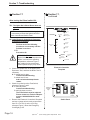
7.1
Section 8
Control Unit Wiring ................................................. 14
Troubleshooting ...................................................... 15
Diesel-Burner Service, Maintenance, and Repair
Information
8.1
General Recommended Maintenance .................... 41
8.2
Detaching and Reattaching the Diesel-Burner ........
Head ....................................................................... 42
8.3
Motor ...................................................................... 43
8.4
Flame Sensor ......................................................... 47
8.5
Ignition Electrodes .................................................. 48
8.6
Fuel Nozzle ............................................................. 50
8.7
Fuel Solenoid .......................................................... 52
8.8
Fuel Pump .............................................................. 54
8.9
Bearings ................................................................. 60
8.10 Ignition Coil ............................................................. 64
8.11
Section 9
Warranty Information
9.0
Section 10
Control Unit ............................................................. 65
Warranty Information .............................................. 70
Spare Parts List
10.0 Spare Parts List ...................................................... 71
Section 11
Special Tools
11.0
R
Special Tools ........................................................... 72
Hydro-Hot Hydronic Heating System Shop Manual 07/03
Section 1: General Heater Information
Component
Overview
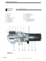
1.1
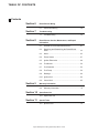
Component Overview
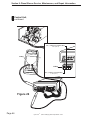
Figure 1
R
Hydro-Hot Hydronic Heating System Shop Manual 07/03
Page 1
Section 1: General Heater Information
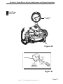
I.D. Plate
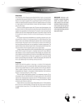
1.2
Identification Plate
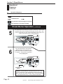
For Installation Only in Compartment Completely
Closed Off from Living Quarters and Accessible
Only from the Outdoors
Exhaust system MUST NOT terminate beneath
the vehicle or under an openable window or vent.
HHE-500-07M
12 VDC / 170 Watts
Model Number
Diesel-Burner / DC Power
Combustion Air MUST BE supplied
from outside the vehicle.
CAUTION: This appliance operates on
both AC and DC Electrical Power.
The AC Powered Electrical Heating Element can be
wired using flexible nonmetallic cable (ROMEX).
USE COPPER CONDUCTORS ONLY
HM02-224
120 VAC, 60 Hz / 1.65 kW
Serial Number
Electric Heating
Element / AC Power
06-02
DIESEL / 50,000 BTU
Manufactured Date
Fuel Type / Firing Rate
Testing
Engineers
International
Complies with the requirements
of UL 307A
Made in U.S.A.
CAUTION: The Mixing / Anti-Scald Valve
must be installed with this product.
Use 25 Amp fuse for over current protection
for DC Power supply.
Use 20 Amp Circuit Breaker for over current
protection for AC Power supply.
Mount Heater near a Bay / Storage Door so
Acess Cover can be easily removed.
Minimum Heater clearances
Front - Open Acess
Back - 8 inches
Top - 9 inches
Sides - 0 inches
Install in strict compliance with local codes, NFPA
501c and manufacturer’s instructions.
Manufactured
Date Box
Reference Figure 1 for
I.D. Plate locations.
Serial Number
Box
Model Number
Box
Figure 2
Page 2
R
Hydro-Hot Hydronic Heating System Shop Manual 07/03
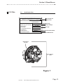
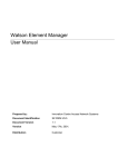
") - Indicates "Polarity Sensitive" Connections
- Indicates Interior Room / Fresh Water Tank
Thermostats
- Indicates Cozy III Heat Exchangers
TSTAT
Bathroom Heating
Zone
+ oorraannggee
-
+ bblluuee
-
+ white
-
white
+ vviioolleett
-
+
-
+
-
brown -
violet +
orange -
yellow +
blue -
blue +
+brleadck
-
+brleadck
-
+brleadck
-
+brleadck
-
white -
green +
B3 INDIC
B6 INDIC
PREHEAT +
PREHEAT -
ELECTRIC +
ELECTRIC -
DIESEL +
DIESEL -
INDICATOR LIGHT -
12 Volt-DC
Battery
Connections
B3
B6
INDICATOR LIGHT +
B4
B2
GROUND BATTERY +
C7
C1
B1
THERM. WHITE
ON/OFF SWITCH
THERM. ORANGE
NOTE:
The two-way plug connector is used
ONLY when replacing older
Hydro-Hot Electronic Controllers.
JP 4
A
B-PLUG
B
Diesel-Burner
Control Unit
C
C-PLUG
Wiring
iring Diagram
Diagram
4-brown
3-red
2-blue
1-green
7-yellow
6-white
5-orange
1-red
2-black
3-brown
5-violet
4-green
7-red
6-white
11-orange
10-yellow
9-yellow
8-brown
16-red
15-red
14-black
13-black
12-orange
yellow
green
brown
blue
black
For Technical Support call 1-800-685-4298
12 VDC - (Ground)
Screw Terminal /
Black wire
-
Switch Panel
Connections
Diesel-Burner
Control Unit
Wiring
GND +12V
12 VDC + (Positive)
Screw Terminal /
Red wire
JP 2
# 1 THERM +
# 1 THERM -
# 1 FAN +
# 1 FAN -
# 2 THERM +
# 2 THERM -
# 2 FAN +
# 2 FAN -
STPUMP STPUMP +
ZPUMP2 ZPUMP2 +
# 3 THERM +
# 3 THERM -
ZPUMP1 ZPUMP1 +
PHPUMP PHPUMP +
# 3 FAN +
# 3 FAN -
Field Wiring
Connections
Component Wiring
Connections
LTCO SW LTCO SW +
# 4 THERM +
# 4 THERM -
# 4 FAN +
# 4 FAN -
# 5 THERM +
# 5 THERM -
AC REL SW AC REL SW +
TSTAT SW TSTAT SW +
JP 3
Electronic
lectronic Controller
Controller
LWCO SW LWCO SW +
R
Black
Black
C -8
C-6
C-5
C-4
C-2
Stir Pump
Circulation Pump #2
Circulation Pump #1
Engine Preheat Pump
Low Temperature
Thermostat
Common
VAC High-Limit
Thermostat
Burner Motor
Diesel-Burner Components
White
120 VAC Power Supply
VDC / VAC
Control Thermostat
Black
120 VAC/1650 Watt
Electric Heating Element
VAC Element Relay
ZETTLER
AZ2280-1A-12D
Float Switch
Hydro-Hot Components
Figure 3
Ignition coil
Flame Sensor
Fuel Solenoid
VDC High-Limit
Thermostat
2455RM8589-6 L220
CAUTION: Reversed polarity to the
12 Volt-DC Battery Connections will
seriously damage the Electronic
Controller.
+
-
"ENGINE
PREHEAT" "ELECTRIC" "DIESEL"
Switch Panel,
Backside View
TSTAT
TSTAT
Bedroom Heating
Zone
-
+
Hydro-Hot Hydronic Heating System Shop Manual 07/03
R
Living Room /
Kitchen
Heating Zone
TSTAT
Fresh Water Tank
Heating Zone
Accessory / Optional
Heating Zone
# 5 FAN -
+
VEHICLE
SYSTEMS
INC.
HYDRO-HOT
Note: All wire colors shown, for "Field Wiring Connections",
CONTROLLER
and "Switch Panel Connections" may vary from actual OEM
/ Converter wiring colors.
JP 1 # 5 FAN +
("
TSTAT
K ey
Section 2: Wiring Information
GEMS
2455RM8589-6 L220
Page 3
Section 3: General Heater Information
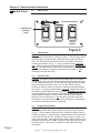
Switch Panel
3.0
Switch Panel
���
� �����
��������
TM
R
By Vehicle Systems
Diesel-Burner’s
Indicator
Light
Diesel
3.1
Electric
Diesel Switch
Engine
Preheat
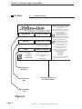
Figure 4
Function: The Diesel switch activates the indicator light on the switch and
the Hydro-Hot's Diesel-Burner, reference Figure 4. This procedure allows
the Diesel-Burner to operate and supply heat to the Hydro-Hot's Boiler
Tank. The Diesel-Burner will heat the Hydro-Hot System to maximum
operating temperature (190�F {+/- 5 deg.}) in approximately 10-20 minutes. Please note that the Diesel-Burner is the Hydro-Hot's primary heat
source for heating both the interior and/or the domestic hot water (such
as when cool ambient temperatures exist and/or when there is a high
demand for domestic hot water).
3.2
Electric Switch
Function: The Electric switch activates the indicator light on the switch
and the Hydro-Hot's 120 VAC Electric Heating Element, reference Figure
4. This procedure allows the 120 VAC Electric Heating Element to supply
heat to the Hydro-Hot's Boiler Tank. The 120 VAC Electric Heating
Element will heat the Hydro-Hot System to maixmum operating temperature (190�F {+/- 5 deg.}) in approximately 1-2 hours. Please note the 120
VAC Electric Heating Element is the Hydro-Hot's secondary heat source
for heating both the interior and/or the domestic hot water during low
heating demand situations (such as when moderate ambient temperatures exist and/or when there is a low demand for domestic hot water).
This feature is only operational whenever the motorhome is connected to
VAC power or when the generator is operating.
3.3
Engine Preheat Switch
Function: The Engine Preheat switch activates the indicator light on the
switch and the Hydro-Hot's Engine Preheat Circulation Pump, reference
Figure 4. This procedure allows the Engine Preheat Circulation Pump to
circulate the engine's coolant through a separate double wall copper loop
in the Hydro-Hot's Boiler Tank, resulting in a warm engine for easy startups on cool mornings. Please note that this feature will be effective only if
the Engine Preheat switch is ON in conjunction with either the Diesel and/
or Electric switch. This feature is available on HHE-200 Model HydroHot's, ONLY.
Page 4
R
Hydro-Hot Hydronic Heating System Shop Manual 07/03
Section 4: General Heater Information
Electronic
Controller
4.0
Electronic Controller
���
� �����
��������
TM
R
Electronic
Controller
Emergency
Cutoff
Electric Heating
Element Status
Low Voltage
Hydro-Hot
Heating Status
Reset
Engine Preheat
Pump
#5
#4
Circulation
Pump #1
Heating Zones
Status
#3
Circulation
Pump #2
#2
#1
Stir Pump
Low Battery
Voltage Fault
Diesel-Burner
Status
Low Temp
Cutoff Status
Overload Fault
Figure 5
4.1
Electric Heating Element Status Indicator Light
This indicator light will illuminate GREEN whenever the Hydro-Hot's 120
VAC Electric Heating Element is operating and providing heat to the HydroHot's Boiler Tank, reference Figure 5. Please note that this light will only be
active if the Electric switch is in the ON position, reference Figure 4. If this
indicator light illuminates RED, it indicates an electrical overload condition
(i.e. short) has occurred in the Electric Heating Element's VDC powered
circuitry.
4.2
Heating Zones Status Indicator Lights
These five indicator lights (separately) will illuminate GREEN whenever a
Zone Thermostat, for each particular zone, is calling for heat, reference
Figure 5. The GREEN indicator lights also indicate that VDC power is being
supplied to the particular interior heating zone's Heat Exchangers (i.e. fan
motors). If any of the five indicator lights illuminate RED, it indicates that an
electrical overload condition (i.e. short) has occurred in a particular heating
zone's circuitry.
NOTE: A short in either a heating zone's Thermostat or a heating zone's
Heat Exchanger circuit, will cause the indicator light to illuminate RED.
R
Hydro-Hot Hydronic Heating System Shop Manual 07/03
Page 5
Section 4: General Heater Information
Electronic
Controller,
continued
4.3
Low Voltage Reset (Button)
The Hydro-Hot's Electronic Controller must be manually reset whenever the
Low Battery Voltage fault indicator light has been activated, reference
Figure 5. To reset the Electronic Controller, simply depress the "Low
Voltage Reset" button located on the Electronic Controller (use a thin
straight object to access the reset button through the small hole in the
faceplate).
4.4
Emergency Cutoff Indicator Light
This indicator light will illuminate RED when either the 120 VAC Electric
Heating Element and/or the Diesel-Burner have automatically shutdown
due to a low water and antifreeze solution level inside the Hydro-Hot's
Boiler Tank, reference Figure 5. This fault will automatically reset when the
low level condition is corrected.
4.5
Heating Status Indicator Light
This indicator light will illuminate GREEN whenever the Hydro-Hot's VDC /
VAC Control Thermostat is calling for heat, allowing the water and
antifreeze solution in the Hydro-Hot's Boiler Tank to be heated by either the
Diesel-Burner and/or the 120 VAC Electric Heating Element, reference
Figure 5. When this indicator light is off, no heat is being supplied to the
Hydro-Hot's Boiler Tank. Please note that this light will only be active if
either the Diesel and/or the Electric switch are turned ON, reference Figure
4.
NOTE: The Hydro-Hot's VDC / VAC Control Thermostat will automatically activate the Diesel-Burner and/or the 120 VAC Electric Heating
Element, only if the Diesel and/or Electric switch is in the ON position.
So to heat the motorhome / domestic hot water, simply choose the
desired heat source(s) and leave the switch(s) (i.e. Diesel and/or
Electric) ON.
4.6
Engine Preheat Pump Indicator Light
This indicator light will illuminate GREEN whenever the Engine Preheat
Pump is operating, reference Figures 1 and 5. Please note that this light
will only be active if the Engine Preheat switch is ON in conjunction with
either the Diesel and/or the Electric switch, reference Figure 4. If this
indicator light illuminates RED, it indicates an electrical overload condition
(i.e. short) has occurred in this particular component's circuitry.
4.7
Circulation Pump #1 Indicator Light
This indicator light will illuminate GREEN whenever Circulation Pump #1 is
operating, reference Figures 1 and 5. Please note that this light will only be
active if the Hydro-Hot is at normal operating temperature (i.e. between
160�� F and 190�� F) and if either Heating Zone #1 or #5 are calling for heat,
reference Figure 3. If this light illuminates RED, it indicates an electrical
overload condition (i.e. short) has occurred in this particular component's
circuitry.
Page 6
R
Hydro-Hot Hydronic Heating System Shop Manual 07/03
Section 4: General Heater Information
Electronic
Controller,
continued
4.8
Circulation Pump #2 Indicator Light
This indicator light will illuminate GREEN whenever Circulation Pump #2 is
operating, reference Figures 1 and 5. Please note that this light will only be
active if the Hydro-Hot is at normal operating temperature (i.e. between
160�� F and 190�� F) and if either Heating Zones #2, #3, or #4 are calling for
heat, reference Figure 3. If this light illuminates RED, it indicates an
electrical overload condition (i.e. short) has occurred in this particular
component's circuitry.
4.9
Stir Pump Indicator Light
This indicator light will illuminate GREEN whenever there is a continuous
demand for domestic hot water (i.e. during a shower), reference Figures 1
and 5. Please note that this light will be active only when the Diesel switch
is turned ON, reference Figure 4.
4.10
Low Battery Voltage Fault Indicator Light
This indicator light will illuminate RED whenever the VDC voltage level is
too low for the Hydro-Hot to operate properly, reference Figure 5. This fault
must be manually reset after the voltage level has been restored to the VDC
battery system, reference Section 4.3 for reset instructions.
4.11
Low Temp Cutoff Status Indicator Light
This indicator light will illuminate GREEN whenever the Hydro-Hot is able to
provide heat for both the Interior and Fresh Water Tank Heating Zones,
reference Figure 5. Whenever this indicator light is OFF, it indicates that
domestic hot water is being used on a continuous basis (i.e. during a
shower).
NOTE: The Hydro-Hot will not provide both interior zone heating and a
continuous supply of domestic hot water simultaneously; Domestic Hot
Water will take priority over Interior Heating. This is referred to as the
"Domestic Water Priority System".
4.12
Diesel-Burner Status Indicator Light
This indicator light will illuminate GREEN whenever the Hydro-Hot's DieselBurner is operating and supplying heat to the Hydro-Hot's Boiler Tank,
reference Figures 1 and 5. Please note that this light will only be active if
the Diesel switch is turned ON, reference Figure 4.
4.13
Overload Fault Indicator Light
This indicator light will illuminate RED (reference Figure 5) whenever one of
the following conditions have occurred:
1. The Hydro-Hot is off due to an electrical overload (i.e. short) in the
main VDC power supply circuitry.
2. The Hydro-Hot is off due to a combination of high electrical VDC
power loads and a high surface temperature of the Electronic
Controller.
The Hydro-Hot will automatically restart once the electrical overload (i.e.
short) and/or high heat condition is corrected.
R
Hydro-Hot Hydronic Heating System Shop Manual 07/03
Page 7
Section 5: Diesel-Burner
Component
Overview
1.
2.
3.
4.
5.
6.
7.
8.
9.
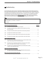
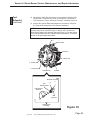
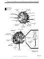
5.1
Component Overview
10.
11.
12.
13.
14.
15.
16.
Control Unit
Motor
Ignition Coil
Clutch
Combustion Air Blower
Fuel Solenoid
Electrode Holder
Ignition Electrodes
Fuel Nozzle
Heat Exchanger
Combustion Chamber
Exhaust Port
Flame Sensor
Fuel Pump
Fuel Ports (Supply / Return)
Combustion Air Intake Port,
with Adjustable Shutter
Figure 6
Page 8
R
Hydro-Hot Hydronic Heating System Shop Manual 07/03
Section 5: Diesel-Burner
Operational
Flow-Chart
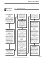
5.2
Operational Flow-Chart
~ Reference Figure 6 for all numbers indicated inside parenthesis. (e.g. #8).
Operation sequence once the
Hydro-Hot’s Diesel switch is
turned ON.
NOTE:
The Diesel switch’s Indicator
Light will illuminate (reference
Figure 4), while the Hydro-Hot
Heating Status and DieselBurner Status lights illuminate
on the Electronic Controller,
reference Figure 5.
The Motor (#2), which turns
the Combustion Air Blower
(#5) and drives the Fuel Pump
(#14), will begin to operate.
NOTE:
If the Hydro-Hot’s coolant
temperature is approximately
190 (+/- 5 deg.) degrees
fahrenheit, or higher, the Motor
(#2) will not operate. Only
when the coolant temperature
has dropped below 160 (+/- 5
deg.) degrees fahrenheit, and
the VDC / VAC Control
Thermostat (see Figure 3) is
calling for heat, will the Motor
(#2) begin to operate.
Simultaneously the Ignition
Coil (#3) produces a high
voltage spark across the
Ignition Electrodes (#8),
which ignites the incoming
air-fuel mixture.
Once the heater switches OFF,
thermostatically or manually,
the Fuel Solenoid (#6) closes,
which interrupts the supply of
diesel fuel to the Fuel Nozzle
(#9).
Once the ignited air-fuel
mixture (FLAME) is observed
by the Flame Sensor (#13),
the Ignition Coil (#3) will
automatically switch OFF. The
combustion process now
continues to operate
unassisted.
The Motor (#2) will continue
to run for approximately three
(3) additional minutes. This
process is refered to as the
purge-cycle, which cools
down the heater’s internal
components and purges the
Combustion Chamber (#11)
of any residual exhaust
gases.
The combustion process will
continue to operate in this
manner until one of the following
take’s place:
When the Hydro-Hot’s DieselBurner is switched OFF, by the
VDC / VAC Control Thermostat
(see Figure 3), the following
process will take place:
A.) The VDC / VAC Control
Thermostat (see Figure 3),
which senses coolant
temperature, reaches the preset
temperature of approximately
190 (+/-5 deg.) degrees
fahrenheit.
NOTE:
If process "A" occurs, the Low
Temp Cutoff Status, Hydro-Hot
Heating Status, and DieselBurner Status lights on the
Electronic Controller will go
OFF, reference Figure 5.
B.) The Hydro-Hot’s Diesel
switch is turned OFF.
NOTE:
If process "B" occurs, the Diesel
switch’s Indicator Light, on the
Switch Panel (reference Figure
4), will go OFF along with the
Hydro-Hot Heating Status,
Diesel-Burner Status, and Stir
Pump lights on the Electronic
Controller, reference Figure 5.
After approximately 10 - 25
seconds, the Fuel Solenoid
(#6) opens and fuel is
sprayed into the
Combustion Chamber (#11)
through the Fuel Nozzle (#9).
R
Hydro-Hot Hydronic Heating System Shop Manual 07/03
NOTE:
1.) The Motor (#2) will shut-off
once the three (3) minute purgecycle has expired.
-THEN2.) The Hydro-Hot’s DieselBurner will automatically turn
back ON once the coolant
temperature reaches the preset
temperature of approximately
160 (+/- 5 deg.) degrees
fahrenheit.
SUMMARY:
The Hydro-Hot’s Diesel-Burner
is operational anytime the
operator activates the Diesel
switch (reference Figure 4) to
the ON position. The DieselBurner will then automatically
maintain the coolant
temperature in the Hydro-Hot’s
Boiler Tank without additional
involvement from the operator.
Page 9
Section 5: Diesel-Burner
Operational
Sequence
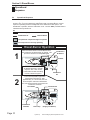
5.3
Operational Sequence
The following sequence illustrates how the Hydro-Hot’s Diesel-Burner operates once it is
activated. Also, if you are experiencing malfunctions with your Diesel-Burner, use this
sequence of operating events as a diagnostic tool to determine at what point, in the
Diesel-Burner’s operation, does the malfunction occur. Use the "KEY" provided below to
understand each symbol shown.
KEY
Diesel Fuel Spray
Exhaust Gases
Combustion Air
The particular component begins to operate.
The component is currently operating.
Diesel-Burner Operation
1
When the Diesel switch is turned ON, the Motor
and Combustion Air Blower begin to operate. This
process is referred to as the prime-cycle.
Motor
NOTE: The Motor and Combustion
Air Blower will begin to operate
only if the VDC / VAC Control
Thermostat is closed and calling
for heat, reference Figure 3.
2
The Fuel Pump builds up pressure
against the Fuel Solenoid. After
approximately 10 - 25 seconds, the Fuel
Solenoid opens and fuel is released into
the Fuel Nozzle and then sprayed into the
Combustion Chamber.
Fuel Nozzle
Combustion
Chamber
Page 10
Combustion
Air Blower
Fuel Pump
R
Combustion
Air
Fuel Solenoid
Diesel Fuel
(Supply and Return)
Hydro-Hot Hydronic Heating System Shop Manual 07/03
Section 5: Diesel-Burner
Operational
Sequence,
continued
5.3
Operational Sequence
KEY
Diesel Fuel Spray
Combustion Air
Exhaust Gases
The particular component begins to operate.
The component is currently operating.
Diesel-Burner Operation, continued
The Ignition Coil produces a high voltage spark, which is transferred
across the Ignition Electrodes. The incoming air-fuel mixture is then
ignited, creating combustion.
3
Ignition Coil
Ignition
Electrodes
Combustion
The combustion’s flame is detected by the
Flame Sensor and the Ignition Coil is then
automatically switched off (no more spark
across the Ignition Electrodes).
4
Hot Exhaust
Gases
R
Flame
Sensor
Hydro-Hot Hydronic Heating System Shop Manual 07/03
Page 11
Section 5: Diesel-Burner
Operational
Sequence
continued
5.3
Operational Sequence
KEY
Diesel Fuel Spray
Combustion Air
The particular component begins to operate.
The component is currently operating.
Diesel-Burner Operation, continued
5
6
The Diesel-Burner will continue to operate continuously in this manner
(produce heat) until it is switched off manually, or by the VDC / VAC
Control Thermostat once the coolant temperature in the Hydro-Hot’s
Boiler Tank reaches 190 (+/- 5 deg.) farenheit.
Once the Diesel-Burner has switched
OFF, the Motor and Combustion Air
Blower will continue to operate for approx.
2-3 minutes. This process is referred to
as the purge-cycle.
Cool Exhaust
Gases
NOTE: If the Diesel-Burner is switched off by the VDC / VAC
Control Thermostat, it will automatically reactivate the DieselBurner whenever the Hydro-Hot Boiler Tank’s coolant temperature
has dropped below 160 (+/- 5 deg.) degrees fahrenheit.
Page 12
R
Hydro-Hot Hydronic Heating System Shop Manual 07/03
Section 5: Diesel-Burner
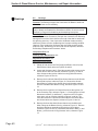
I.D. Plate
5.4
Identification Plate
Fabrikschild-Duplikat
gultig nur zusammen mit Original
Thermosysteme GmbH
To be shipped with
Original Heater
MADE IN GERMANY
DBW 2010.75
HEIZGERAT Typ
Spannung / El. Leistung
12 V / 60W
13,2 kW
Warmestrom
Brennstoff
Diesel
zul. Betriebsuberdruck
2 bar
Prufzeichen
Fabriknummer
1B230410
Inbetriebnahmejahr
2001 2002 2003
Model Type
Voltage / Wattage
Fuel Type
Serial Number (230410)
Year Manufactured
Diesel-Burner
I.D. Plate
Diesel-Burner
Head
Figure 7
R
Hydro-Hot Hydronic Heating System Shop Manual 07/03
Page 13
Section 6: Diesel Burner Wiring
Control
Unit Wiring
6.1
Control Unit Wiring
NOTE: Reference Figure 3 for all "JP" Plug
and Pin locations on the Electronic Conroller.
C-1 ( + ) VDC / VAC Control Thermostat
Circuit (Orange Wire) to JP-4 (Pin 5).
C-2 ( + ) Motor Circuit (Black Wire)
to Diesel-Burner.
B-3 (+) Indicator Light Circuit (Blue
Wire) to JP-4, (Pin 2).
C-4 ( - ) VDC High-Limit Thermostat
Circuit (Blue Wire) to Hydro-Hot’s
Boiler Tank.
B-2 ( - ) Battery Circuit (Brown Wire)
to JP-4 (Pin 4)
B-1 ( + ) On / Off Switch
Circuit, with Low Voltage
Protection (Yellow Wire) to
JP-4 (Pin 7).
B-Plug
B-1 B-2 B-3
B-6
B-4
C-4
C-1 C-2
C-5 C-6 C-7 C-8
C-Plug
C-8 ( + ) Ignition Coil Circuit (Yellow Wire)
to Diesel-Burner.
B-4 ( + ) Battery Circuit (Red Wire)
to JP-4 (Pin 3)
C-7 ( + ) VDC / VAC Control Thermostat Circuit
(White Wire) to JP-4 (Pin 6).
B-6 ( - ) Indicator Light Circuit
(Green Wire) to JP-4 (Pin 1).
C-6 ( + ) Flame Sensor Circuit (Green Wire)
to Diesel-Burner.
C-5 ( - ) Ground Circuit (Brown Wire), for
Diesel-Burner components, to Diesel-Burner.
Figure 8
Page 14
R
Hydro-Hot Hydronic Heating System Shop Manual 07/03
Section 7: Troubleshooting
Troubleshooting
This Troubleshooting Section has been separated into different Hydro-Hot Troubleshooting Scenario's,
that may be experienced by the heater. Each section listed below begins with the most probable cause
and remedy, to the least probable cause and remedy. This concept has been put in place to expedite the
troubleshooting process and pinpoint the problem quickly. However, if you need additional assistance,
please feel free to contact our Technical Department at 1-800-685-4298 or e-mail them by going to
www.vehiclesys.com and clicking on the Technical Support button. Also, please review the following
"KEY", prior to troubleshooting, as it may be helpful in understanding each nomenclature.
KEY:
TS#: (i.e. TS1, TS2, ....) = Troubleshooting Scenario 1, Troubleshooting Scenario 2, ....
Q#: (i.e. Q1, Q2,....) = Question 1, Question 2, ....
A: = Answer
After turning the Diesel switch ON:
Section
TS1 - The Hydro-Hot's Diesel-Burner does not operate. ................................................................. 7.1
TS2 - The Hydro-Hot's Diesel-Burner operates (3-minute prime cycle only), ...................................
but does not ignite. ................................................................................................................ 7.2
TS3 - The Hydro-Hot's Diesel-Burner ignites after several starting attempts. .................................. 7.3
TS4 - The Hydro-Hot's exhaust system sputters. ............................................................................ 7.4
TS5 - The Hydro-Hot's exhaust system produces white smoke after ignition. ................................. 7.5
TS6 - The Hydro-Hot's exhaust system produces black smoke after ignition. ................................. 7.6
Other troubleshooting issues:
TS7 - The Hydro-Hot is at operating temperature, but an Interior and/or Fresh ...............................
Water Tank Heating Zone is not producing heat. .................................................................. 7.7
TS8 - The Hydro-Hot is at operating temperature, but the fans of an Interior ..................................
and/or Fresh Water Heat Exchangers are not operating. ....................................................... 7.8
TS9 - The Hydro-Hot is at operating temperature, but the domestic hot water
system is not producing hot water. ........................................................................................ 7.9
After turning the Electric switch ON:
TS10 - The Hydro-Hot's 120 VAC Electric Heating Element does not operate
(i.e. lack of hot water and/or interior heat). ............................................................................. 7.10
After turning the Engine Preheat switch ON:
TS11 - The Hydro-Hot's Engine Preheat System does not preheat the engine. ................................ 7.11
R
Hydro-Hot Hydronic Heating System Shop Manual 07/03
Page 15
Section 7: Troubleshooting
Section 7.1,
continued
Section 7.1
After turning the Diesel switch ON:
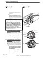
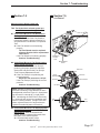
TS1: The Hydro-Hot's Diesel-Burner does not
operate.
NOTE: In order to perform the following checks,
it is necessary to locate the Hydro-Hot's Electronic Controller and Switch Panel.
���
� �����
��������
TM
R
Electronic
Controller
Emergency
Cutoff
Electric Heating
Element Status
Low Voltage
Hydro-Hot
Heating Status
Reset
Q1: Is the Electronic Controller's Emergency
Cutoff light Illuminated?
A: If YES:
Perform each of the following
procedures as necessary until the
problem is resolved.
If NO:
Proceed to Q2.
#4
Circulation
Pump #1
Heating Zones
Status
#3
Page 16
R
Circulation
Pump #2
#2
#1
Stir Pump
Low Battery
Voltage Fault
WARNING: DO NOT remove the
Hydro-Hot's Radiator Cap when the
heater is at maximum operating
temperature, reference Figure 1.
Hot coolant can be present and
serious personal injury may result.
a. Check the coolant level in the Hydro-Hot's
Expansion Tank, and then the Boiler Tank if
necessary.
A: If coolant level is okay:
Continue troubleshooting.
If coolant level is low:
Add coolant and attempt heater
restart.
b. Check for continuity at the Float Switch,
reference Figures 1 and 3.
A: If continuity exists:
Continue troubleshooting.
If continuity does not exist:
The Float Switch must be replaced.
Please contact our Technical Department at 1-800-685-4298 for assistance.
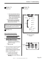
c. Remove the Electronic Controller's Faceplate
and use a jumper wire to make a connection
from Pin 15 to Pin 16 on the JP-3 Plug,
reference Figure 3. Does the Emergency
Cutoff light go off?
Engine Preheat
Pump
#5
Diesel-Burner
Status
Low Temp
Cutoff Status
Overload Fault
Electronic Controller
Faceplate
���
� �����
��������
TM
R
By Vehicle Systems
Diesel-Burner’s
Indicator
Light
Diesel
Hydro-Hot Hydronic Heating System Shop Manual 07/03
Electric
Switch Panel
Engine
Preheat
Section 7: Troubleshooting
Section 7.1,
continued
Section 7.1,
continued
A: If YES:
Check the JP-3 Plug for loose wire
connections and/or harness damage.
If NO:
The Electronic Controller must be
replaced. Please contact our Technical Department at 1-800-685-4298 for
assistance.
Q2: Is the Electronic Controller's Low Battery
Voltage Fault light illuminated?
A: If YES:
Perform each of the following
procedures as necessary until the
problem is resolved.
If NO:
Proceed to Q3.
a. Remove the Electronic Controller's Faceplate.
Check the DC battery voltage level at the
supply batteries and at the Electronic
Controller's Battery Connections, reference
Figure 3. Both voltage readings should be
between 11.5 and 14.0 volts.
A: If the voltage level is within specs:
Continue troubleshooting.
If the voltage level is out of specs:
Recharge and/or replace batteries, if
necessary.
b. Reset the Low Voltage Reset (button) on the
Electronic Controller (this can be accomplished by using a thin straight object to
access the reset button through the small
hole in the Faceplate). Continue to read the
voltage level at the Electronic Controller's
Battery Connections and then turn the Diesel
switch ON. Under load, is the voltage level
within 0.5 volts of the supply battery's voltage?
A: If YES:
See the "NOTE" at the top right of
this page.
If NO:
Load-test the supply batteries,
inspect battery wiring for damage
R
and/or loose connections, and
ensure that all of the Hydro-Hot's
electrical motors are operating
normally when under load.
NOTE: If after testing and correcting the battery
system, the Low Battery Voltage Fault indicator
light continues to illuminate, and/or if the Low
Voltage Reset (button) will not reset, the Electronic Controller must be replaced. Please
contact our Technical Department at 1-800685-4298 for assistance.
Q3: Is the Electronic Controller's DieselBurner Status light illuminated?
A: If NO:
Perform each of the following
procedures as necessary until the
problem is resolved.
If YES:
Proceed to Q5.
a. Remove the Electronic Controller's Faceplate.
Use a jumper wire to make a connection from
the Diesel (+) to the Diesel (-) on the JP-2
Plug, reference Figure 3. Does the DieselBurner Status light illuminate?
A: If YES:
The Diesel switch must be replaced.
Please contact our Technical Department at 1-800-685-4298 for assistance. Attempt heater restart.
If NO:
Continue troubleshooting.
b. Turn the Diesel switch OFF (also, make sure
the Electric switch is OFF ). Use a jumper
wire to make a connection from Pin 13 to Pin
14 on the JP-3 Plug, reference Figure 3. With
the jumper wire in place, turn the Diesel
switch ON. Does the Diesel-Burner ignite and
the Diesel-Burner Status light illuminate?
A: If YES:
The VDC / VAC Control Thermostat
must be replaced, reference Figure
3. Please contact our Technical
Hydro-Hot Hydronic Heating System Shop Manual 07/03
Page 17
Section 7: Troubleshooting
Section 7.1,
continued
Section 7.1,
continued
Department at 1-800-685-4298 for
assistance.
If NO:
The Electronic Controller must be
replaced. Please contact our Technical Department at 1-800-685-4298 for
assistance.
NOTE: If no problems were discovered up to
this point, the problem most likely lies within
the Diesel-Burner Head. However, prior to
troubleshooting the Diesel-Burner Head, be
sure to review the "Operational Flow-Chart"
in Section 5.2, the "Operational Sequence"
in Section 5.3, and the "Function" section for
each of the Diesel-Burner Components,
reference Sections 8.3 thru 8.11. This information may help determine at what point the
Diesel-Burner fails to operate.
Q4: Is the Diesel-Burner's Motor operating?
Quick Check - Listen at the heater for the
Diesel-Burner's Motor to operate, or check for
output air at the heater's exhaust pipe.
A: If the Motor does not seem to be operating:
Reference Section 8.3 and perform
the Motor's "Component Test".
If the Motor is operating:
Continue troubleshooting.
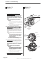
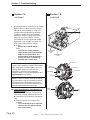
Q5: Is the Diesel-Burner's Control Unit functioning properly?
In order to determine if the Control Unit is
functioning properly, reference Section 8.11
and perform the Control Unit's "Component
Test".
A: If the Control Unit is not functioning properly:
The Control Unit must be replaced,
reference Section 8.11 for replacement instructions.
If the Control Unit is functioning properly:
See the "NOTE" on the top left-hand
side of the following page.
Page 18
R
Diesel-Burner
Control
Unit
Diesel-Burner
Head
Ignition Coil
Ignition
Electrodes
Flame Sensor
Photo Disc
Fuel Solenoid
Fuel Pump
Control
Unit
Hydro-Hot Hydronic Heating System Shop Manual 07/03
Fuel
Nozzle
Section 7: Troubleshooting
Section 7.1,
continued
Section 7.2,
continued
NOTE: If the Hydro-Hot still does not operate
after performing all of the listed checks, contact
our Technical Department at 1-800-685-4298 for
additional assistance.
Section 7.2
After turning the Diesel switch ON:
TS2: The Hydro-Hot's Diesel-Burner operates
(3-minute prime cycle only), but does
not ignite.
NOTES:
A. It is ideal to have the Hydro-Hot's Fuel Filter
replaced yearly, reference Section 8.1. A
plugged Fuel Filter will not allow the DieselBurner to operate properly. Also, before
proceeding on to the following procedures,
be sure to check that the vehicle's fuel
tank has a sufficient level of fuel.
B. In order to perform some of the following
procedures it may be necessary to detach
the Diesel-Burner Head from the Hydro-Hot.
Therefore, be sure to reference Section 8.2
for detaching and reattaching instructions.
Q1: Has the Hydro-Hot's VDC High-Limit Thermostat tripped?
Locate the VDC High-Limit Thermostat and
check for continuity, reference Figure 1. Is
continuity present?
A: If YES:
Proceed to Q2.
If NO:
Press the red reset button located on
the VDC High-Limit Thermostat and
attempt heater restart.
NOTE: Although the Diesel-Burner is now
functioning, be sure to perform the following
steps until the cause for overheating has been
discovered and corrected. Failure to do so
could result in another overheating condition.
R
a. Turn the Diesel switch ON and allow the
Hydro-Hot to reach operating temperature
(i.e. until the Diesel-Burner cycles OFF).
Locate both the VDC High-Limit Thermostat
and the VAC / VDC Control Thermostat and
check them for continuity, reference Figure 1.
A: If there is no continuity at the VDC HighLimit Thermostat, but there is continuity at
the VAC / VDC Control Thermostat:
The VAC / VDC Control Thermostat
must be replaced. Please contact
our Technical Department at 1-800685-4298 for assistance.
If there is continuity at the VDC High-Limit
Thermostat, but none at the VAC / VDC
Control Thermostat:
The overheat condition may have
been caused by another faulty
component and no further troubleshooting is necessary, see the
"NOTE" below and please contact
our Technical Department at 1-800685-4298 for additional assistance.
NOTE: If the VDC High-Limit Thermostat
continues to trip, and no overheating problems
were discovered (i.e. faulty VAC / VDC Control
Thermostat or Control Unit), it may be that the
VDC High-Limit Thermostat is not operating
properly and it may need to be replaced.
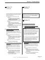
Q2: Is the Diesel-Burner's Fuel Nozzle functioning properly?
In order to determine if the Fuel Nozzle is
functioning properly, reference Section 8.6
and perform the Fuel Nozzle's "Component
Test".
A: If the Fuel Nozzle is not functioning
properly:
The Fuel Nozzle must be replaced,
reference Section 8.6 for replacement instructions.
If the Fuel Nozzle is functioning properly:
Continue Troubleshooting.
Hydro-Hot Hydronic Heating System Shop Manual 07/03
Page 19
Section 7: Troubleshooting
Section 7.2,
continued
Section 7.2,
continued
Q3: Is the Diesel-Burner's Fuel Solenoid
functioning properly?
In order to determine if the Fuel Solenoid is
functioning properly, reference Section 8.7
and perform the Fuel Solenoid's "Component
Test".
A: If the Fuel Solenoid is not functioning
properly:
The Fuel Solenoid must be replaced,
reference Section 8.7 for replacement
instructions.
If the Fuel Solenoid is functioning properly:
Continue Troubleshooting.
Q4: Is the Diesel-Burner's Control Unit functioning properly?
In order to determine if the Control Unit is
functioning properly, reference Section 8.11
and perform the Control Unit's "Component
Test".
A: If the Control Unit is not functioning properly:
The Control Unit must be replaced,
reference Section 8.11 for replacement instructions.
If the Control Unit is functioning properly:
Continue Troubleshooting.
Q5: Is the Diesel-Burner's Ignition Coil functioning properly?
In order to determine if the Ignition Coil is
functioning properly, reference Section 8.10
and perform the Ignition Coil's "Component
Test".
A: If the Ignition Coil is not functioning
properly:
The Ignition Coil must be replaced,
reference Section 8.10 for replacement instructions.
If the Ignition Coil is functioning properly:
Continue Troubleshooting.
Diesel-Burner
Control
Unit
Diesel-Burner
Head
Ignition Coil
Ignition
Electrodes
Flame Sensor
R
Fuel Solenoid
Fuel Pump
Control
Unit
Q6: Are the Diesel-Burner's Ignition Electrodes
in good condition and properly adjusted?
Page 20
Photo Disc
Hydro-Hot Hydronic Heating System Shop Manual 07/03
Fuel
Nozzle
Section 7: Troubleshooting
Section 7.2,
continued
Section 7.2,
continued
In order to determine if the Ignition Electrodes
are in good condition and properly adjusted,
reference Section 8.5.
A: If the Ignition Electrodes are in poor
condition:
The Ignition Electrodes must be
replaced, reference Section 8.5 for
replacement instructions.
If the Ignition Electrodes are not properly
adjusted:
Adjust the Ignition Electrodes,
reference Section 8.5 for adjustment
instructions.
If the Ignition Electrodes are both in good
condition and properly adjusted:
Continue Troubleshooting.
Q7: Is the Diesel-Burner's Flame Sensor
functioning properly?
In order to determine if the Flame Sensor is
functioning properly, reference Section 8.4
and perform the Flame Sensor's "Component
Test".
A: If the Flame Sensor is not functioning
properly:
The Flame Sensor must be replaced,
reference Section 8.4 for replacement instructions.
If the Flame Sensor is functioning properly:
Continue Troubleshooting.
Q8: Is the Diesel-Burner's Fuel Pump functioning properly?
In order to determine if the Fuel Pump is
functioning properly, reference Section 8.8
and perform the Fuel Pump's "Component
Test".
A: If the Fuel Pump is not functioning properly:
The Fuel Pump must be replaced,
reference Section 8.8 for replacement instructions.
If the Fuel Pump is functioning properly:
See the "NOTE" below.
R
NOTE: If the Hydro-Hot still does not ignite after
performing all of the listed checks, contact our
Technical Department at 1-800-685-4298 for
additional assistance.
Section 7.3
After turning the Diesel switch ON:
TS3: The Hydro-Hot's Diesel-Burner ignites
after several starting attempts.
NOTES:
A. It is ideal to have the Hydro-Hot's Fuel Filter
replaced yearly, reference Section 8.1. A
plugged Fuel Filter will not allow the DieselBurner to operate properly. Also, before
proceeding to the following procedures,
be sure to check that the vehicle's fuel
tank has a sufficient level of fuel.
B. In order to perform the following procedures,
it is necessary to detach the Diesel-Burner
Head from the Hydro-Hot. Be sure to
reference Section 8.2 for detaching and
reattaching instructions.
Q1: Is the Diesel-Burner's Fuel Nozzle functioning properly?
In order to determine if the Fuel Nozzle is
functioning properly, reference Section 8.6
and perform the Fuel Nozzle's "Component
Test".
A: If the Fuel Nozzle is not functioning
properly:
The Fuel Nozzle must be replaced,
reference Section 8.6 for replacement
instructions.
If the Fuel Nozzle is functioning properly:
Continue Troubleshooting.
Hydro-Hot Hydronic Heating System Shop Manual 07/03
Page 21
Section 7: Troubleshooting
Section 7.3,
continued
Section 7.3,
continued
Q2: Is the Diesel-Burner's Flame Sensor functioning properly?
In order to determine if the Flame Sensor is
functioning properly, reference Section 8.4
and perform the Flame Sensor's "Component
Test".
A: If the Flame Sensor is not functioning
properly:
The Flame Sensor must be replaced,
reference Section 8.4 for replacement instructions.
If the Flame Sensor is functioning properly:
Continue Troubleshooting.
Q3: Are the Diesel-Burner's Ignition Electrodes
in good condition and properly adjusted?
In order to determine if the Ignition Electrodes
are in good condition and properly adjusted,
reference Section 8.5.
A: If the Ignition Electrodes are in poor
condition:
The Ignition Electrodes must be
replaced, reference Section 8.5 for
replacement instructions.
If the Ignition Electrodes are not properly
adjusted:
Adjust the Ignition Electrodes,
reference Section 8.5 for adjustment
instructions.
If the Ignition Electrodes are both in good
condition and properly adjusted:
Continue Troubleshooting.
Q4: Is the Diesel-Burner's Fuel Pump functioning properly?
In order to determine if the Fuel Pump is
functioning properly, reference Section 8.8
and perform the Fuel Pump's "Component
Test".
A: If the Fuel Pump is not functioning
properly:
The Fuel Pump must be replaced,
reference Section 8.8 for replacement instructions.
If the Fuel Pump is functioning properly:
Page 22
R
Diesel-Burner
Control
Unit
Diesel-Burner
Head
Ignition Coil
Ignition
Electrodes
Flame Sensor
Photo Disc
Fuel Solenoid
Fuel Pump
Control
Unit
Hydro-Hot Hydronic Heating System Shop Manual 07/03
Fuel
Nozzle
Section 7: Troubleshooting
Section 7.3,
continued
Section 7.3,
continued
Continue Troubleshooting.
Fuel Filter
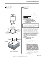
Q5: Is the Diesel-Burner's Fuel Supply System
functioning properly?
Quick Check - With the Diesel-Burner ignited,
listen for constant sputtering from the HydroHot's exhaust system.
A: If constant sputtering exists:
Continue Troubleshooting.
If constant sputtering does not exist:
Proceed to Q6.
NOTE: Inspect the clear bowl of the Fuel Filter
for water. If water exists, be sure to purge the
Hydro-Hot's entire fuel system prior to replacing
the Fuel Filter. Attempt heater restart.
TOP VIEW:
of Fuel Filter Head
Plug
input
from Fuel Tank /
fuel pick-up
2
4
1
3
output to
Hydro-Hot’s Fuel
"Supply" Port
Plug
SUPPLY PORT:
to Hydro-Hot’s
Fuel Filter
RETURN PORT:
from Hydro-Hot’s
"Return" Port
dedicated
fuel pick-up
Fuel Pick-up Pipe Illustration
R
a. Clamp off and remove the Hydro-Hot's Fuel
Return Line, reference Figure 1. Now attach
a short piece of fuel line to the Hydro-Hot's
Fuel Return Port and place the other end in a
container of diesel fuel. Remove the clamp
and ensure that the fuel line is completely
submersed in the fuel and then turn the Diesel
switch ON. Are air bubbles visible in the
container of fuel when the Diesel-Burner is
operating?
A: If air bubbles are not visible:
Proceed to Q6.
If air bubbles are visible:
You will need to inspect the fuel
system (supply side) for air leaks.
Therefore, be sure to perform the
inspections listed below until the air
leak has been detected:
1. Inspect the fuel system (supply
side) from the vehicle's fuel tank
to the Diesel-Burner. Inspect the
fuel connections at the Hydro-Hot,
Diesel-Burner, and at the vehicle's
fuel tank for looseness. Tighten if
necessary. Also, check that all
Fuel Filter Head fittings are securely tightened; see the "NOTE"
at the top left-hand side of the
following page.
Hydro-Hot Hydronic Heating System Shop Manual 07/03
Page 23
Section 7: Troubleshooting
Section 7.3,
continued
Section 7.3,
continued
NOTE: Be sure to check that each fitting at the
Fuel Filter Head contains thread sealant. A
fitting without thread sealant could result in an
air leak. Be sure to clamp off both fuel lines at
the filter head prior to any fitting removal. If
fittings are removed and reinstalled, be sure to
remove the fuel line clamps prior to attempting a
heater restart. Failure to do so could result in
serious damage to the Diesel-Burner's Fuel
Pump.
2. Once the potential air leak has
been discovered and corrected,
reattach the Hydro-Hot's Fuel
Return Line and attempt heater
restart. Does the Hydro-Hot's exhaust system still sputter?
If the exhaust system is still sputtering:
Perform the air leak inspections
again, until all air leaks have been
discovered and corrected.
Q6: Is the Diesel-Burner's Control Unit functioning properly?
In order to determine if the Control Unit is
functioning properly, reference Section 8.11
and perform the Control Unit's "Component
Test".
A: If the Control Unit is not functioning
properly:
The Control Unit must be replaced,
reference Section 8.11 for replacement instructions.
If the Control Unit is functioning properly:
Continue Troubleshooting.
reference Section 8.10 for replacement instructions.
If the Ignition Coil is functioning properly:
See the "NOTE" below.
NOTE: If the Hydro-Hot still does not ignite
after several starting attempts and all of the
listed checks were performed, contact our
Technical Department at 1-800-685-4298 for
additional assistance.
Ignition Coil
Ignition
Electrodes
Flame Sensor
R
Fuel Solenoid
Fuel Pump
Control
Unit
Q7: Is the Diesel-Burner's Ignition Coil functioning properly?
In order to determine if the Ignition Coil is
functioning properly, reference Section 8.10
and perform the Ignition Coil's "Component
Test".
A: If the Ignition Coil is not functioning properly:
The Ignition Coil must be replaced,
Page 24
Photo Disc
Hydro-Hot Hydronic Heating System Shop Manual 07/03
Fuel
Nozzle
Section 7: Troubleshooting
Section 7.4
Section 7.4,
continued
After turning the Diesel switch ON:
TS4: The Hydro-Hot's exhaust system sputters.
Fuel Filter
NOTE: Before proceeding to the following
procedures, be sure to check that the vehicle's
fuel tank has a sufficient level of fuel.
Q1: Is the Diesel-Burner's Fuel Nozzle functioning properly?
In order to determine if the Fuel Nozzle is
functioning properly, reference Section 8.6
and perform the Fuel Nozzle's "Component
Test".
A: If the Fuel Nozzle is not functioning
properly:
The Fuel Nozzle must be replaced,
reference Section 8.6 for replacement instructions.
If the Fuel Nozzle is functioning properly:
Continue Troubleshooting.
Q2: Is the Diesel-Burner's Fuel Supply System
functioning properly?
Quick Check - With the Diesel-Burner
ignited, listen for constant sputtering from the
Hydro-Hot's exhaust system.
A: If constant sputtering exists:
Continue Troubleshooting.
NOTE: Inspect the clear bowl of the Fuel Filter
for water. If water exists, be sure to purge the
Hydro-Hot's entire fuel system prior to replacing
the Fuel Filter. Attempt heater restart.
a. Clamp off and remove the Hydro-Hot's Fuel
Return Line, reference Figure 1. Now attach
a short piece of fuel line to the Hydro-Hot's
Fuel Return Port and place the other end in a
container of diesel fuel. Remove the clamp
and ensure that the fuel line is completely
submersed in the fuel and then turn the
Diesel switch ON. Are air bubbles visible in
the container of fuel when the Diesel-Burner
is operating?
A: If air bubbles are not visible:
See the last "NOTE" in this section
(Section 7.4).
R
TOP VIEW:
of Fuel Filter Head
Plug
input
from Fuel Tank /
fuel pick-up
2
4
1
3
SUPPLY PORT:
to Hydro-Hot’s
Fuel Filter
output to
Hydro-Hot’s Fuel
"Supply" Port
Plug
RETURN PORT:
from Hydro-Hot’s
"Return" Port
dedicated
fuel pick-up
Fuel Pick-up Pipe Illustration
Hydro-Hot Hydronic Heating System Shop Manual 07/03
Page 25
Section 7: Troubleshooting
Section 7.4,
continued
Section 7.4,
continued
If air bubbles are visible:
You will need to inspect the fuel
system (supply side) for air leaks.
Therefore, be sure to perform the
inspections listed below until the air
leak has been detected:
1. Inspect the fuel system (supply
side) from the vehicle's fuel tank
to the Diesel-Burner. Inspect the
fuel connections at the HydroHot, Diesel-Burner, and at the
vehicle's fuel tank for looseness.
Tighten if necessary. Also, check
that all Fuel Filter Head fittings
are securely tightened, see the
"NOTE" below.
NOTE: Be sure to check that each fitting at the
Fuel Filter Head contains thread sealant. A
fitting without thread sealant could result in an
air leak. Be sure to clamp off both fuel lines at
the filter head prior to any fitting removal. If
fittings are removed and reinstalled, be sure to
remove both clamps prior to attempting a
heater restart. Failure to do so could result in
serious damage to the Diesel-Burner's Fuel
Pump.
2. Once the potential air leak has
been discovered and corrected,
reattach the Hydro-Hot's Fuel
Return Line and attempt heater
restart. Does the Hydro-Hot's exhaust system still sputter?
If the exhaust system is still sputtering:
Perform the air leak inspections
again, until all air leaks have been
discovered and corrected.
Fuel Filter
TOP VIEW:
of Fuel Filter Head
Plug
input
from Fuel Tank /
fuel pick-up
2
4
1
3
SUPPLY PORT:
to Hydro-Hot’s
Fuel Filter
output to
Hydro-Hot’s Fuel
"Supply" Port
Plug
RETURN PORT:
from Hydro-Hot’s
"Return" Port
dedicated
fuel pick-up
NOTE: If the Hydro-Hot's exhaust system still
sputters after performing all of the listed checks,
contact our Technical Department at 1-800-6854298 for additional assistance.
Fuel Pick-up Pipe Illustration
Page 26
R
Hydro-Hot Hydronic Heating System Shop Manual 07/03
Section 7: Troubleshooting
Section 7.5
Section 7.5,
continued
After turning the Diesel switch ON:
TS5: The Hydro-Hot's exhaust system produces white smoke after ignition.
Q1: Is the Diesel-Burner's Fuel Nozzle functioning properly?
In order to determine if the Fuel Nozzle is
functioning properly, reference Section 8.6
and perform the Fuel Nozzle's "Component
Test".
A: If the Fuel Nozzle is not functioning
properly:
The Fuel Nozzle must be replaced,
reference Section 8.6 for replacement
instructions.
If the Fuel Nozzle is functioning properly:
Continue Troubleshooting.
Q2: Is the Diesel-Burner's Fuel Pump producing the proper pressure?
In order to determine if the Fuel Pump is
producing the proper pressure, reference
Section 8.8 and perform the Fuel Pump's
"Fuel Pressure Adjustment Check".
A: If the Fuel Pump is not producing the
correct pressure:
Adjust the fuel pressure to 145 psi.
If the Fuel Pump is producing the correct
pressure:
Continue Troubleshooting.
NOTE: Be sure to check that the Ignition
Electrode's Retaining Clamp Bolt has not been
overtightened, reference Figure 16. Overtightening can result in a bound-up (i.e. rigid) Photo
Disc. Not allowing the Photo Disc to float freely
(i.e. a loose fit) will cause poor combustion and
result in a smoky exhaust. If a tight Photo Disc
exists, reference Section 8.5 and perform the
"Ignition Electrode Adjustment Procedure".
Diesel-Burner
Control
Unit
Diesel-Burner
Head
Ignition Coil
Ignition
Electrodes
Flame Sensor
Photo Disc
Fuel Solenoid
Fuel Pump
Control
Unit
Fuel
Nozzle
Q3: Is the Diesel-Burner's Fuel Supply System
functioning properly?
Quick Check - With the Diesel-Burner
ignited, look for constant white smoke from
the Hydro-Hot's exhaust system.
A: If constant white smoke exists:
Continue Troubleshooting.
R
Hydro-Hot Hydronic Heating System Shop Manual 07/03
Page 27
Section 7: Troubleshooting
Section 7.5,
continued
Section 7.5,
continued
Fuel Filter
NOTE: Inspect the clear bowl of the Fuel Filter
for water. If water exists, be sure to purge the
Hydro-Hot's entire fuel system prior to replacing
the Fuel Filter. Attempt heater restart.
a. Clamp off and remove the Hydro-Hot's Fuel
Return Line, reference Figure 1. Now attach
a short piece of fuel line to the Hydro-Hot's
Fuel Return Port and place the other end in a
container of diesel fuel. Remove the clamp
and ensure that the fuel line is completely
submersed in the fuel and then turn the
Diesel switch ON. Are air bubbles visible in
the container of fuel when the Diesel-Burner
is operating?
A: If air bubbles are not visible:
Proceed to Q6.
If air bubbles are visible:
You will need to inspect the fuel
system (supply side) for air leaks.
Therefore, be sure to perform the
inspections listed below until the air
leak has been detected:
1. Inspect the fuel system (supply
side) from the vehicle's fuel tank
to the Diesel-Burner. Inspect the
fuel connections at the HydroHot, Diesel-Burner, and at the
vehicle's fuel tank for looseness.
Tighten if necessary. Also, check
that all Fuel Filter Head fittings
are securely tightened, see the
"NOTE" below.
NOTE: Be sure to check that each fitting at the
Fuel Filter Head contains thread sealant. A
fitting without thread sealant could result in an
air leak. Be sure to clamp off both fuel lines at
the filter head prior to any fitting removal. If
fittings are removed and reinstalled, be sure to
remove both clamps prior to attempting a
heater restart. Failure to do so could result in
serious damage to the Diesel-Burner's Fuel
Pump.
Page 28
R
TOP VIEW:
of Fuel Filter Head
Plug
input
from Fuel Tank /
fuel pick-up
2
4
1
3
SUPPLY PORT:
to Hydro-Hot’s
Fuel Filter
output to
Hydro-Hot’s Fuel
"Supply" Port
Plug
RETURN PORT:
from Hydro-Hot’s
"Return" Port
dedicated
fuel pick-up
Fuel Pick-up Pipe Illustration
Hydro-Hot Hydronic Heating System Shop Manual 07/03
Section 7: Troubleshooting
Section 7.5,
continued
Section 7.6,
continued
2. Once the potential air leak has
been discovered and corrected,
reattach the Hydro-Hot's Fuel
Return Line and attempt heater
restart. Does the Hydro-Hot's exhaust system still sputter?
If the exhaust system is still sputtering:
Perform the air leak inspections
again, until all air leaks have been
discovered and corrected.
NOTE: If the Hydro-Hot's exhaust system still
produces white smoke after performing all of the
listed checks, contact our Technical Department
at 1-800-685-4298 for additional assistance.
���
� �����
��������
TM
R
Electronic
Controller
Emergency
Cutoff
Electric Heating
Element Status
Low Voltage
Hydro-Hot
Heating Status
Reset
Engine Preheat
Pump
#5
#4
Circulation
Pump #1
Heating Zones
Status
#3
Circulation
Pump #2
#2
#1
Stir Pump
Low Battery
Voltage Fault
Diesel-Burner
Status
Low Temp
Cutoff Status
Section 7.6
Overload Fault
After turning the Diesel switch ON:
Electronic Controller
Faceplate
TS6: The Hydro-Hot's exhaust system produces black smoke after ignition.
Q1: Is the Electronic Controller's Low Battery
Voltage Fault light illuminated?
A: If YES:
Perform each of the following
procedures as necessary until the
problem is resolved.
If NO:
Proceed to Q2.
a. Remove the Electronic Controller's Faceplate.
Check the DC battery voltage level at the
supply batteries and at the Electronic
Controller's Battery Connections, reference
Figure 3. Both voltage readings should be
between 11.5 and 14.0 volts.
A: If the voltage level is within specs:
Continue troubleshooting.
If the voltage level is out of specs:
Recharge and/or replace batteries, if
necessary.
R
���
� �����
��������
TM
R
By Vehicle Systems
Diesel-Burner’s
Indicator
Light
Hydro-Hot Hydronic Heating System Shop Manual 07/03
Diesel
Electric
Engine
Preheat
Page 29
Section 7: Troubleshooting
Section 7.6,
continued
Section 7.6,
continued
b. Reset the Electronic Controller's Low Voltage
Reset (button) on the Electronic Controller
(this can be accomplished by using a thin
straight object to access the reset button
through the small hole in the faceplate).
Continue to read the voltage level at the
Electronic Controller's Battery Connections and then turn the Diesel switch ON.
Under load, is the voltage level within 0.5
volts of the supply batteries voltage?
A: If YES:
See the first "NOTE" below.
If NO:
Load-test the supply batteries,
inspect battery wiring for damage
and/or loose connections, and
ensure that all of the Hydro-Hot's
electrical motors are operating
normally when under load.
NOTE: If after testing and correcting the battery
system, the Low Battery Voltage Fault indicator
light continues to illuminate, and/or if the Low
Voltage Reset (button) will not reset, the
Electronic Controller must be replaced.
Please contact our Technical Department at 1800-685-4298 for assistance.
Diesel-Burner
Control
Unit
Diesel-Burner
Head
Ignition Coil
Ignition
Electrodes
Flame Sensor
Photo Disc
Fuel Solenoid
Fuel Pump
NOTE: In order to perform some of the following procedures it may be necessary to detach
the Diesel-Burner Head from the Hydro-Hot.
Therefore, be sure to reference Section 8.2 for
detaching and reattaching instructions.
Q2: Is the Diesel-Burner's Fuel Nozzle functioning properly?
In order to determine if the Fuel Nozzle is
functioning properly, reference Section 8.6
and perform the Fuel Nozzle's "Component
Test".
A: If the Fuel Nozzle is not functioning
properly:
The Fuel Nozzle must be replaced,
reference Section 8.6 for replacement instructions.
Page 30
R
Control
Unit
Hydro-Hot Hydronic Heating System Shop Manual 07/03
Fuel
Nozzle
Section 7: Troubleshooting
Section 7.6,
continued
Section 7.6,
continued
If the Fuel Nozzle is functioning properly:
Continue Troubleshooting.
Q3: Is the Diesel-Burner's Motor operating at
the proper RPM speed?
In order to determine if the Motor is operating
properly, reference Section 8.3 and perform
the Motor's "RPM Test".
A: If the Motor is not operating at the proper
RPM:
The Motor must be replaced, reference Section 8.3 for replacement
instructions.
If the Motor is operating at the proper
RPM:
Continue Troubleshooting.
#3 - Plunger
#4 - Rubber Ball
CO2 Gas
Analyzer
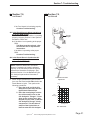
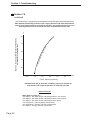
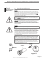
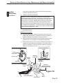
Q4: Is the Diesel-Burner's Combustion Air
Intake adjusted properly?
A: See the "NOTE" below.
NOTE: Inorder to determine if the DieselBurner's Combustion Air Intake is adjusted
properly, a CO2 Gas-Analyzer will be required,
reference the illustration on this page. Also,
reference Section 11 for the Bacharach Fyrite
CO2 Analyzer's part number information, if
necessary.
a. When using the Bacharach Fyrite CO2 Analyzer, turn the Diesel switch ON and allow the
Diesel-Burner to ignite. Then perform the
following procedures:
1. Place the small end of the CO2
Analyzer's suction hose into the
Hydro-Hot's Exhaust Pipe.
2. Place the round plunger connection of the suction hose on the
CO2 Analyzer's "Plunger". Press
down on the suction hose, with
the palm of your hand, so that the
CO2 Analyzer's Plunger" is fully
compressed. This will allow a
sample of the Hydro-Hot's exhaust to enter the CO2 Analyzer.
R
CO2 -
+ CO2
Combustion Air Intake
Adjustment
Vol %
13
12
11
CO2
Percentage
Hydro-Hot Hydronic Heating System Shop Manual 07/03
10
9
8
7
20
10
24 26 28
12
14
DC Voltage Level
22
V-
CO2 - Value Chart
Page 31
Section 7: Troubleshooting
Section 7.6,
continued
Section 7.6,
continued
3. Pump the rubber ball - 18 times.
4. Release the suction hose from the
CO2 Analyzer's plunger.
5. Turn the CO2 Analyzer upside
down so that the fluid runs to the
top and then turn it right side up
again. Perform this procedure
twice.
6. Place the CO2 Analyzer on a flat
surface and read the CO2 level.
7. The CO2 level should be between
10.5 and 11.5 percent (at a nominal 12 volts DC). If the CO2 level is
not within specs, an adjustment of
the Diesel-Burner's Combustion
Air Intake will be necessary,
reference the illustration on the
previous page. Once the proper
CO2 adjustment has been made,
be sure to tighten the adjustment
screw.
Fuel Pump is producing the proper
pressure. In order to determine if the
Fuel Pump is producing the proper
pressure, reference Section 8.8 and
perform the Fuel Pump's "Fuel Pressure
Adjustment Check".
D. Check and reset the Combustion Air
Blower gap, if applicable. In order to
determine if the Combustion Air Blower's
gap is set properly, reference Section 8.9
and perform Steps 1-6 and 11-17 of the
Bearings "Replacement Procedure".
E. See the "NOTE" below.
NOTE: If the Hydro-Hot's exhaust system still
produces black smoke after performing all of
the listed checks, contact our Technical Department at 1-800-685-4298 for additional assistance.
NOTE: For temporary high altitude situations
(less available oxygen) the CO2 will rise by
0.3% CO2 per 1,000 feet of elevation. (e.g. a
Diesel-Burner adjusted at sea level should
register approximately a 1.5% higher CO2
reading when in Denver, Colorado {5,000
above sea level}). If permanently residing in a
high altitude area, be sure to properly adjust
the Diesel-Burner so that it operates within the
10.5% - 11.5% CO2 range.
NOTES: If the proper CO2 - value cannot be
obtained, perform each of the following inspections as necessary until the cause has been
detected:
A. Check the rubber Grommets on the top
and bottom of the Diesel-Burner Head's
cast-aluminum Blower Casing to ensure
they are securely in place.
B. Check the Diesel-Burner Head for proper
alignment. (torque specification = approx.
20-40 in. lbs.), reference Section 8.2.
C. Check to ensure that the Diesel-Burner's
Page 32
R
Hydro-Hot Hydronic Heating System Shop Manual 07/03
Section 7: Troubleshooting
Section 7.7,
continued
Section 7.7
After turning the Diesel switch ON:
TS7: The Hydro-Hot is at operating temperature, but an Interior and/or Fresh Water
Tank Heating Zone is not producing heat.
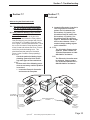
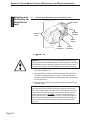
Q1: Is the particular Heating Loop's Circulation Pump operating?
Quick Check - Remove the Hydro-Hot's
Access Cover and determine if the problem
Heat Exchanger(s) are plumbed with Circulation Pump #1 or Circulation Pump #2, reference Figure 1 and the illustration below. Once
the correct Circulation Pump has been determined, locate and activate the Room Thermostat for the particular heating zone. This
should activate that particular Circulation
Pump. Is the Circulation Pump operating?
A: If YES:
Check the particular Heating Loops
plumbing system for kinks and/or
any other types of flow restrictions.
If NO:
Perform each of the following procedures as necessary until the problem
is resolved.
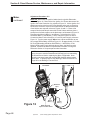
1. Locate the Electronic Controller
and remove the Faceplate.
Living Room
Cozy III Heat
Exchanger
Living Room /
Kitchen Zone
2. Locate the Electronic Controller's
JP-3 Plug and then insert the
probes of a DC voltmeter into
Pin locations 5 (+) and 6 (-) for
Circulation Pump #1, and/or into
Pin locations 3 (+) and 4 (-) for
Circulation Pump #2, reference
Figure 3. Observe the DC voltage
level on the voltmeter. Does a
nominal voltage reading register
on the voltmeter?
A: If YES:
The Circulation Pump must be
replaced. Please contact our
Technical Department at 1-800685-4298 for assistance.
If NO:
The Electronic Controller must
be replaced. Please contact
our Technical Department at 1800-685-4298 for assistance.
Heating
Loop 2
Heating
Loop 1
Living Room
Cozy III Heat
Exchanger
Fresh Water
Tank Zone
Cozy III Heat
Exchanger
Bathroom
Zone
Cozy III Heat
Exchanger
Typical Heat Exchanger
Locations
Bedroom
Zone
Cozy III Heat
Exchanger
Kitchen
Cozy III Heat
Exchanger
R
Hydro-Hot Hydronic Heating System Shop Manual 07/03
Page 33
Section 7: Troubleshooting
Section 7.8,
continued
Section 7.8
After turning the Diesel switch ON:
TS8: The Hydro-Hot is at operating temperature, but the fans of an Interior and/or
Fresh Water Tank Heat Exchangers are
not operating.
Q1: Is the Electronic Controller's Low Temp
Cutoff Status light illuminated?
A: If YES:
Perform each of the following
procedures as necessary until the
problem is resolved.
If NO:
Inspect the Heat Exchanger fans
and interior Room Thermostat wiring
for loose connections at JP-1 Plug of
the Electronic Controller, reference
Figure 3.
a. Activate the interior Room Thermostat and
then turn the Diesel switch ON. Remove the
Hydro-Hot's Access Cover and locate the two
yellow colored wires, which connect to the two
black wires, reference the illustration on this
page. Disconnect the wires and then connect
the two yellow wires together by utilizing an
ATO type automotive fuse, again reference
the illustration. Do the Heat Exchanger fans
now operate?
A: If YES:
The Low Temp Cutoff Thermostat
may need to be replaced. Please
contact our Technical Department at
1-800-685-4298 for assistance.
If NO:
Perform each of the following
procedures as necessary until the
problem is resolved.
1. Locate the Electronic Controller
and remove the Faceplate.
2. Locate the Electronic Controller's
JP-1 Plug and read the DC voltage
signal output, and input, at the
particular interior Room
Thermostat's circuit, reference
Figure 3. Is there an output DC
Page 34
R
���
� �����
��������
TM
R
Electronic
Controller
Emergency
Cutoff
Electric Heating
Element Status
Low Voltage
Hydro-Hot
Heating Status
Reset
Engine Preheat
Pump
#5
#4
Circulation
Pump #1
Heating Zones
Status
#3
Circulation
Pump #2
#2
#1
Stir Pump
Low Battery
Voltage Fault
Diesel-Burner
Status
Low Temp
Cutoff Status
Overload Fault
Electronic Controller
Faceplate
Black wires
Yellow wire
ATO
Fuse
Yellow wire
Black wires
Yellow wires
Hydro-Hot Hydronic Heating System Shop Manual 07/03
Section 7: Troubleshooting
Section 7.9
Section 7.8,
continued
After turning the Diesel switch ON:
voltage signal at the Electronic
Controller?
A: If YES:
The interior Room Thermostat may
need to be replaced. Please contact
our Technical Department at 1-800685-4298 for assistance.
If NO:
The Electronic Controller must be
replaced. Please contact our Technical Department at 1-800-685-4298 for
assistance.
TS9: The Hydro-Hot is at operating temperature, but the domestic hot water system is
not producing hot water.
Q1: Is the Electronic Controller's Stir Pump
Status light illuminated? (reference Figure
5)
A: If YES:
Perform each of the following
procedures as necessary until the
problem is resolved.
1. Seal all openings that may allow
cool air to enter the open area at
the backside of the Hydro-Hot.
2. Locate the Low-Temp Cutoff Thermostat, reference Figure 1. Make
sure that the thermostat has not
been dislodged from the copper
line, reference Figure 1.
3. Turn the Diesel switch ON and
allow the Hydro-Hot to reach it's
maximum operating temperature.
Once the Diesel-Burner has
cycled OFF, check the Low-Temp
Cutoff Thermostat for continuity,
reference Figures 1 and 3. If no
continuity is present, the Low
Temp Cutoff Thermostat must be
replaced. Please contact our
Technical Department at 1-800685-4298 for assistance.
If NO:
Check the Hydro-Hot's heating
solution for the proper antifreeze to
water mixture (should be 33% antifreeze and 67% water). A high
concentration of antifreeze will cause
a poor domestic hot water performance.
NOTE: If there is still a lack of hot water after
performing all of the listed checks, contact our
Technical Department at 1-800-685-4298 for
additional assistance. Also, be sure to reference the chart on the following page regarding
the Hydro-Hot's Domestic Hot Water System.
R
Hydro-Hot Hydronic Heating System Shop Manual 07/03
Page 35
Section 7: Troubleshooting
Section 7.9,
continued
The chart below, is a graphical representation of how the Hydro-Hot’s Domestic Hot
Water System theoretically performs under varying domestic cold water temperatures.
Because each Hydro-Hot has a performance tolerance, this graph should be used as a
general guideline and not as actual domestic hot water performance data.
F
at e
rc
ur v
e
70
dom
e st
ic h
ot w
60
50
115
F
Input (i.e. incoming) Temperature of Domestic
Cold Water to the Hydro-Hot
80
40
0.5
1.0
1.5
2.0
2.5
3.0
GPM
(GPM - Gallons per Minute)
Estimated flow rate, of domestic cold water, required to maintain an
approximate 115 F output temperature of domestic hot water.
Notes of interest:
When water is heated to.....
156 degrees - Hot water causes a third-degree burn in one second
149 degrees - Hot water causes a third-degree burn in two seconds
133 degrees - Hot water causes a third-degree burn quickly
115-120 degrees - General purpose temperatures
107-109 degrees - Average "Hot-Tub" temperatures
105 degrees - Average "Shower" temperature
Page 36
Section 7: Troubleshooting
Section 7.10
Section 7.10,
continued
After turning the Electric switch ON:
TS10: The Hydro-Hot's 120 VAC Electric Heating Element does not operate (i.e. lack of
hot water and/or interior heat).
Q1: Is the Electronic Controller's Electric
Heating Element Status light illuminated?
(reference Figure 5)
A: If YES:
Perform each of the following procedures as necessary until the problem
is resolved.
1. Locate the Electronic Controller
and remove the Faceplate.
2. Locate the Electronic Controller's
JP-3 Plug and check for DC
voltage at Pin 11 (+) and Pin 12 (-),
reference Figure 3.
A: If voltage is present:
Check for loose wire connections
at Pin 11 (+) and Pin 12 (-) of the
JP-3 Plug. If the wire connections are in good condition,
proceed to Q2.
If no voltage is present:
Replace the Electronic Controller.
Please contact our Technical
Department at 1-800-685-4298 for
assistance.
If NO:
Perform each of the following procedures as necessary until the problem
is resolved.
1. Locate the Electronic Controller
and remove the Faceplate.
2. Locate the Electronic Controller's
JP-2 Plug. Use a jumper wire to
make a connection from the
Electric (+) pin to the Electric (-)
pin, reference Figure 3. Does
Electronic Controller's Electric
Heating Element Status light
illuminate?
A: If the Electric Heating Element Status
light illuminates:
Check for loose wire connections
at Electric switch and at the JP-2
Plug's Electric (+) and Electric (-)
pins. If connections are in good
condition, replace the Electric
switch.
If the Electric Heating Element
Status light did not illuminate:
Locate the Electronic Controller's
JP-2 Plug and check for DC
voltage at the Electric (+) and
Electric (-) pins, reference Figure
3.
If no voltage is present:
Replace the Electronic Controller.
Please contact our Technical
Department at 1-800-685-4298 for
assistance.
Q2: Has the Hydro-Hot's VAC High-Limit Thermostat tripped?
WARNING: Turn the VAC breaker
OFF prior to performing the following checks. Failure to do so may
result in serious bodily injury (i.e.
electrical shock).
Remove the 4 in. x 4 in. Electric Heating
Element Access Panel and locate the VAC
High-Limit Thermostat, reference Figure 1.
Check for continuity at the VAC High-Limit
Thermostat. Is continuity present?
A: If YES:
Proceed to Q3.
If NO:
Press the red reset button located on
the VAC High-Limit Thermostat.
Reset the VAC breaker and then turn
the Electric switch ON.
NOTE: Although the 120 VAC Electric Heating
Element is now functioning, be sure to perform
the following steps until the cause for overheating has been discovered and corrected.
Failure to do so could result in another overheating condition.
Page 37
Section 7: Troubleshooting
Section 7.10,
continued
Section 7.10,
continued
a. Turn the Diesel and Electric switches ON and
allow the Hydro-Hot to reach maximum
operating temperature (i.e. until the DieselBurner cycles OFF). Locate both the VAC
High-Limit Thermostat and the VAC / VDC
Control Thermostat and check for continuity,
reference Figure 1.
A: If there is no continuity at the VAC HighLimit Thermostat, but there is continuity at
the VAC / VDC Control Thermostat:
The VAC / VDC Control Thermostat
must be replaced. Please contact
our Technical Department at 1-800685-4298 for assistance.
If there is continuity at the VAC High-Limit
Thermostat, but none at the VAC / VDC
Control Thermostat:
The overheat condition may have
been caused by another faulty
component and no further troubleshooting is necessary, see the
"NOTE" below. Please contact our
Technical Department at 1-800-6854298 for additional assistance.
NOTE: If the VDC High-Limit Thermostat
continues to trip, and no overheating problems
were discovered (i.e. faulty VAC / VDC Control
Thermostat), it may be that the VDC High-Limit
Thermostat is not operating properly and it may
need to be replaced.
Q3: Is VAC power being supplied to the VAC
Element Relay?
WARNING: The following checks
need to be performed with the
motorhome connected to VAC
power. Be sure to use extreme
caution when performing each
check, as 120 VAC power will be
present at each of the electrical
components. Failure to do so may
result in serious bodily injury (i.e.
electrical shock).
Page 38
R
Turn the Electric switch ON. Locate the VAC
Element Relay in the 4 in. x 4 in. junction box,
reference Figure 1. Check for AC voltage at
the Black (+) wire ("120 VAC Power Supply")
connection at the AC Element Relay, reference Figure 3. For a common ground, use
the White wire connection at the 120 VAC
Electric Heating Element. Is voltage present?
A: If YES:
Proceed to Q4.
If NO:
Check for loose wire connections
at the motorhome's VAC junction
box. If the wire connections are in
good condition, please contact our
Technical Department at 1-800-6854298 for additional assistance.
Q4: Is VAC Element Relay functioning properly?
WARNING: The following checks
need to be performed with the
motorhome connected to VAC
power. Be sure to use extreme
caution when performing each
check, as 120 VAC power will be
present at each of the electrical
components. Also, be sure to
disconnect VAC power prior to
replacing any electrical components. Failure to do so may result
in serious bodily injury (i.e. electrical shock).
NOTE: Inspect the VAC Element Relay for
damage. If visual signs of damage exist, the
relay must be replaced.
Turn the Electric switch ON. Locate the VAC
Element Relay in the 4 in. x 4 in. junction box.
Check for AC voltage at the Black (+) wire
(from the VAC High-Limit Thermostat) connection at the AC Element Relay, reference
Figure 3. For a common ground, use the
Hydro-Hot Hydronic Heating System Shop Manual 07/03
Section 7: Troubleshooting
Section 7.10,
continued
Section 7.10,
continued
White wire connection at the 120 VAC Electric
Heating Element. Is voltage present?
A: If YES:
Proceed to Q5.
If NO:
The VAC Element Relay must be
replaced. Please contact out Technical Department at 1-800-685-4298 for
assistance.
Q5: Is 120 VAC Electric Heating Element
functioning properly?
WARNING: The following checks
need to be performed with the
motorhome connected to VAC
power. Be sure to use extreme
caution when performing each
check, as 120 VAC power will be
present at each of the electrical
components. Also, be sure to
disconnect VAC power prior to
replacing any electrical components. Failure to do so may result
in serious bodily injury (i.e. electrical shock).
Disconnect the motorhome from VAC shore
power. Locate the 120 VAC Electric Heating
Element in the 4 in. x 4 in. junction box.
Remove the White (common) wire from the
120 VAC Electric Heating Element. Check for
continuity at the Black (+) wire and at the
terminal where the White (common) wire was
removed. Is continuity present?
A: If YES:
See the "NOTE" on the top righthand side of this page.
If NO:
The 120 VAC Electric Heating Element must be replaced. Please
contact out Technical Department at
1-800-685-4298 for assistance.
R
NOTE: If the 120 VAC Electric Heating Element
still does not seem to operate after performing
all of the listed checks, contact our Technical
Department at 1-800-685-4298 for additional
assistance.
Section 7.11
After turning the Engine Preheat switch ON:
TS11: The Hydro-Hot's Engine Preheat System
does not preheat the engine.
NOTE: The Diesel or Electric switch must be
activated, along with the Engine Preheat
switch, prior to performing the following checks.
Q1: Is the Electronic Controller's Engine
Preheat Pump light illuminated? (reference
Figure 5)
A: If YES:
Perform each of the following procedures as necessary until the problem is resolved.
1. Locate the Electronic Controller
and remove the Faceplate.
2. Locate the Electronic Controller's
JP-3 Plug and check for DC
voltage at Pin 7 (+) and Pin 8 (-),
reference Figure 3.
A: If voltage is present:
Check for loose wire connections
at Pin 7 (+) and Pin 8 (-) of the JP3 Plug. Also, check the wire connections at the Engine Preheat
Pump. If all connections are in
good condition, listen and feel the
Engine Preheat Pump to ensure
that it is operating, reference
Figure 1. If the Engine Preheat
Pump is not operating, it must be
replaced.
Hydro-Hot Hydronic Heating System Shop Manual 07/03
Page 39
Section 7: Troubleshooting
Section 7.11,
continued
If no voltage is present:
Replace the Electronic Controller.
If NO:
Perform each of the following procedures as necessary until the problem
is resolved.
1. Locate the Electronic Controller
and remove the Faceplate.
2. Locate the Electronic Controller's
JP-2 Plug. Use a jumper wire to
make a connection from the
Preheat (+) pin to the Preheat (-)
pin, reference Figure 3. Does
Electronic Controller's Engine
Preheat Pump light illuminate?
A: If the Engine Preheat Pump light
illuminates:
Check for loose wire connections
at Engine Preheat switch and at
the JP-2 Plug's Preheat (+) and
Preheat (-) pins, reference Figure
3. If connections are in good
condition, replace the Engine
Preheat switch.
If the Engine Preheat Pump light did
not illuminate:
Locate the Electronic Controller's
JP-2 Plug and check for DC
voltage at the Preheat (+) and
Preheat (-) pins, reference Figure
3.
If no voltage is present:
Replace the Electronic Controller.
Please contact our Technical
Department at 1-800-685-4298 for
assistance.
If voltage is present:
See "NOTE" below.
NOTE: If the Engine Preheat Pump still does
not seem to operate after performing all of the
listed checks, contact our Technical Department
at 1-800-685-4298 for additional assistance.
Page 40
R
Hydro-Hot Hydronic Heating System Shop Manual 07/03
Section 8: Diesel-Burner Service, Maintenance, and Repair Information
General
Recommended
Maintenance
8.1
General Recommended Maintenance
Monthly
Check the Hydro-Hot's water and antifreeze solution to ensure that it is at
the proper level. Do this by visually checking the coolant level in the HydroHot's Expansion Tank, reference Figure 1. This should be checked only
when the Hydro-Hot is at maximum operating temperature (i.e. when the
Diesel-Burner cycles OFF), "HOT".
WARNING: When the Hydro-Hot is at maximum operating temperature
(HOT), DO NOT loosen the Radiator Cap. If removed, scalding by hot
vapor or coolant could result.
If the coolant needs replenishing, fill the Hydro-Hot's Expansion Tank to the
FULL HOT level mark. Be sure to reference the Hydro-Hot "Owner's
Manual" for the proper antifreeze type and mixture. If coolant frequently
needs replenishing, please contact our Technical Department at 1-800-6854298 for assistance.
Annually
WARNING: Before cleaning or servicing, disconnect all power supplies.
To keep your Hydro-Hot running smoothly, it is ideal to have the DieselBurner tuned-up annually. A tune-up should consist of a new Fuel Nozzle
and Fuel Filter, along with a thorough cleaning of the Combustion Chamber,
if necessary (reference Figure 9). To ensure maximum Diesel-Burner
performance, always use the recommended Fuel Nozzle and Fuel Filter
(i.e. 10 Micron) when replacing these parts. Reference Section 10 for
spare parts information.
NOTE: Be sure to use care when handling the Fuel Nozzle. Oils and/or
small dust or dirt particles from your hands may plug the nozzle's small
orifice. A partially plugged orifice will restrict fuel flow, which will affect
the combustion process of the Diesel-Burner (i.e. excessive smoking).
CAUTION: Operating the Hydro-Hot's Diesel-Burner or the 120 VAC
Electric Heating Element, without the water and antifreeze solution, will
cause serious damage to the heater.
Combustion
Chamber
Fuel Nozzle
(0.35 GPH)
Fuel Filter
(10 Micron)
small orifice
Figure 9
R
Hydro-Hot Hydronic Heating System Shop Manual 07/03
Page 41
Section 8: Diesel-Burner Service, Maintenance, and Repair Information
Detaching and
Reattaching the
Diesel-Burner
Head
8.2
Detaching and Reattaching the Diesel-Burner Head
Grommets
Eye-Bolts
and Nuts
Diesel-Burner
Head
Blower
Casing
Diesel
Fuel Supply
Diesel
Fuel Return
Figure 10
WARNING: Be sure to turn the Diesel switch OFF and disconnect the
B-Plug Harness from the Diesel-Burner's Control Unit prior to detaching
the Diesel-Burner Head, reference Figures 8 and 26. Failure to do so
may result in the ignition of the Diesel-Burner and serious bodily injury.
1. Loosen the two Eye-Bolt Nuts and swing the Eye-Bolts out of the
way, reference Figure 10.
2. With both hands, carefully pull the Diesel-Burner Head away from
the Hydro-Hot (approximately 4-5 inches). Please note that you
may have to lift the Diesel-Burner Head slightly while pulling it away
from the Hydro-Hot.
3. Rotate the Diesel-Burner Head upward until all the internal components are visible.
CAUTION: When reattaching the Diesel-Burner Head, be sure to
properly align the Diesel-Burner Head before tightening the Eye Bolt
Nuts. Also, visually inspect all of the rubber Grommets on the top and
bottom of the Diesel-Burner Head's cast-aluminum Blower Casing to
ensure they are in place. DO NOT over tighten the Eye-Bolt Nuts
(torque specification = approx. 20-40 in. lbs.). An improper alignment
and/or an over tightening of the Eye-Bolt Nuts can cause damage to
the Diesel-Burner Head's cast-aluminum Blower Casing, reference
Figure 10.
Page 42
Section 8: Diesel-Burner Service, Maintenance, and Repair Information
Motor
8.3
Motor
Function: The Motor drives the Combustion Air Blower and the Fuel
Pump.
NOTE: In order to perform the following procedures, it may be necessary to detach and reattach the Diesel-Burner Head. Be sure to reference Section 8.2, Page 42 for detaching and reattaching instructions.
Component Test: Locate the Control Unit's C-Plug and insert the probes
of a DC voltmeter into the C-2 (+) and C-5 (-) locations, reference Figure
11. Turn the Diesel switch ON and observe the voltage level. If a nominal
voltage registers on the voltmeter and the Motor is not operating, inspect
the C-Plug Harness for loose or damaged wire connections. If the C-Plug
Harness and connections are in good condition, the Motor must be replaced, reference the Motor's "Replacement Procedure" on Page 45.
Cleaning Tips / Maintenance: N/A
C-2 ( + ) Motor Circuit (Black Wire)
to Diesel-Burner.
12.5 V
COM (-)
(+)
C-4
C-1 C-2
C-5 C-6 C-7 C-8
C-Plug
C-5 ( - ) Ground Circuit (Brown Wire), for
Diesel-Burner components, to Diesel-Burner.
Figure 11
Page 43
Section 8: Diesel-Burner Service, Maintenance, and Repair Information
Motor,
continued
Adjustment Procedure: N/A
RPM Test: Disconnect the Ignition Cables from the Ignition Electrodes,
reference Figure 16. Remove the four Ignition Coil Screws that secure the
Ignition Coil to the Protection Cap, reference Figure 13. Lift the Ignition Coil
and disconnect its wires from the C-Plug Harness wires prior to removing.
Remove the Protection Cap from the Diesel-Burner so that the Motor and
Clutch Halves are exposed, reference Figures 12 and 13. Place a few
wraps of black electrical tape around the Clutch Halves and then place a
small piece of reflective tape over the black tape, as illustrated in Figure 12.
Disconnect the Motor's Black (+) and Brown (-) wires from the C-Plug
Harnesses Black (+) and Brown (-) wires, reference Figures 12 and 13.
Connect the Motor's wires directly to a 12 volt DC power supply, reference
Figure 12. Turn the power supply ON and use a photo-tachometer to test
for a proper RPM reading, reference Figure 12. At approximately 12.5 volts
DC, the RPM reading should be 4500 RPM's (+/- 300 RPM's). If the
Motor's RPM reading is not within the above specs, the Motor must be
replaced, reference the Motor's "Replacement Procedure" on Page 45.
Reference Section 10 for spare part number information.
NOTE: If the Motor's RPM reading is out of specs, or even if within
specs, be sure to test the Diesel-Burner's Bearings prior to reattaching
the Diesel-Burner Head or replacing the Motor, if applicable. Worn
Bearings can cause lower than normal RPM readings and premature
Motor wear. To properly test for worn Bearings, reference Section 8.9,
Page 60 for the Bearings "Function Test".
Photo
Tachometer
450
0 RP
M
Reflective
Tape
Motor
Black
Wire (+)
Figure 12
Page 44
Brown
Wire (-)
Black Electrical
Tape on Clutch Halves
R
Hydro-Hot Hydronic Heating System Shop Manual 07/03
Section 8: Diesel-Burner Service, Maintenance, and Repair Information
Motor,
continued
Replacement Procedure:
1. Remove the four Ignition Coil Screws that secure the Ignition Coil to
the Protection Cap, reference Figure 13. Lift the Ignition Coil to
disconnect its wires from the C-Plug Harness wires prior to removing. Remove the Protection Cap from the Diesel-Burner so that the
Motor and Clutch Halves are exposed, reference Figures 13 and 14.
2. Remove the three Hex Head Screws that secure the Motor and
flange assembly to the Blower Housing, reference Figure 13.
Remove the Motor and flange assembly along with the Clutch
Halves, reference Figures 13 and 14. Disconnect the Motor's Black
(+) and Brown (-) wires from the C-Plug Harness' wires, reference
Figure 13.
NOTE: Inspect the Clutch Halves' for cracks and also ensure that the
flat portion in each shaft hole is free of wear and tear. Too much play on
the shaft produces a loud clacking noise. If any cracks or wear are
detected, the Clutch Half must be replaced. Reference the Hydro-Hot's
"Parts Manual" for spare parts information.
3. Detach the Motor from the Motor Flange by removing the two
Phillips Head Screws that fasten the two parts together, reference
Figure 13.
NOTES:
A: Be sure to test the Diesel-Burner's Bearings prior to reinstalling the
Motor. Worn Bearings can cause lower than normal RPM readings
and premature Motor wear. To properly test for worn Bearings,
reference Section 8.9, Page 60 for the Bearings "Function Test"..
B: The Motor must be mounted to the flange with the wires and drain
hole pointing downward and the recessed edge of the Motor Flange
pointing upward, reference Figure 14. This will ensure a proper
Protection Cap fit.
4. Reinstall a Clutch Half on both the new Motor's shaft and the
Combustion Air Blower's shaft. Attach the Motor and flange assembly, with the recessed edge of the Motor Flange in-line with the
wiring access slot of the Blower Casing, to the Blower Housing with
the three Hex Head Screws, reference Figure 14.
NOTE: Inspect the Blower Casing's O-Ring for damage or wear prior to
reinstalling the Diesel-Burner Head's Protection Cap, reference Figure
14. If damage or wear exists, replace the O-Ring. Reference the HydroHot's "Parts Manual" for spare parts information.
5. Connect the Black (+) and Brown (-) wires of the new Motor to the
C-Plug Harness' Black (+) and Brown (-) wires, reference Figure 13.
Feed the C-Plug Harness' Yellow and Brown wires back through the
wiring access hole in the Protection Cap, reference Figure 14.
6. Reinstall the Protection Cap. Reconnect the Black (+) and Brown (-)
wires of the Ignition Coil to the C-Plug Harness' Yellow (+) and
Brown (-) wires, reference Figure 24. Reinstall the Ignition Coil and
R
Hydro-Hot Hydronic Heating System Shop Manual 07/03
Page 45
Section 8: Diesel-Burner Service, Maintenance, and Repair Information
Motor,
continued
secure to the Protection Cap with the four Ignition Coil Screws,
reference Figure 13.
Figure 13
Figure 14
Page 46
R
Hydro-Hot Hydronic Heating System Shop Manual 07/03
Section 8: Diesel-Burner Service, Maintenance, and Repair Information
Flame
Sensor
8.4
Flame Sensor
Function: The Flame Sensor is a photoresistive device which supplies
the Diesel-Burner's Control Unit with a DC voltage signal when it detects
a flame (i.e. light source).
NOTES:
A: In order to perform the following procedures it is necessary to
detach and reattach the Diesel-Burner Head. Be sure to review
Section 8.2, Page 42 for detaching and reattaching instructions.
B: Be sure to calibrate your ohmmeter prior to checking the Flame
Sensor for proper resistance values.
Component Test: Locate and detach the Flame Sensor's Green and Blue
wires from the C-Plug Harness wires, reference Figure 15. Connect the
Flame Sensor's Green and Blue wires to an ohmmeter, reference Figure
15. Check resistance by placing a shop rag over the Flame Sensor's glass
surface, to simulate a no flame condition, and then remove the rag (and
expose to a light source) to simulate a flame condition. If the Flame
Sensor is operating properly, the ohmmeter should register high resistance
(i.e. 100K �����when the glass surface is covered, and less than 300 �
when exposed to a light source. If these resistance numbers cannot be
obtained, the Flame Sensor must be replaced, reference the Flame
Sensor's "Replacement Procedure" below. Reference Section 10 for spare
parts information.
Cleaning Tips / Maintenance: For light dirt, dust, and/or carbon deposits,
simply wipe off the Flame Sensor with a soft cloth. Should heavy carbon
deposits be present, completely remove the Flame Sensor from the Photo
Disc and clean with brake cleaner, reference Figure 15.
Adjustment Procedure: N/A
Replacement Procedure:
1. Remove the Screw that fastens the Flame Sensor to the Photo Disc
and detach the sensor's Green and Blue wires from the C-Plug
Harness' Green and Violet wires, reference Figure 15.
2. Slide the tab of the new Flame Sensor into the provided slot in the
Photo Disc and secure in place with the screw, reference Figure 15.
Connect the Flame Sensor's Green wire to the Green C-Plug
Harness wire and the Blue wire to the C-Plug Harness' Violet
wire, reference Figure 15.
R
Hydro-Hot Hydronic Heating System Shop Manual 07/03
Page 47
Section 8: Diesel-Burner Service, Maintenance, and Repair Information
Flame
Sensor,
continued
Flame
Sensor
Green
Wire
Photo
Disc
Green Wire
(to Diesel-Burner)
Blue
Wire
Figure 15
Ignition
Electrodes
8.5
NOTE: This screw is used to
fasten the Flame Sensor to
the Photo Disc. Remove
when replacing the Flame
Sensor.
Violet Wire
(to Diesel-Burner)
Ignition Electrodes
Function: The Diesel-Burner's Ignition Coil (reference Figure 24) produces a high voltage ignition spark across the Ignition Electrodes, which
ignites the incoming air / fuel mixture.
NOTE: In order to perform the following procedures it is necessary to
detach and reattach the Diesel-Burner Head. Be sure to review Section
8.2, Page 42 for detaching and reattaching instructions.
Component Test: N/A
Cleaning Tips / Maintenance: Polish away any carbon deposits that may
have baked onto the metal tips of the Ignition Electrodes with a scotch
brite pad (or similar), reference Figure 16. If the Ignition Electrode's
electrical insulator (reference Figure 16) is cracked and/or damaged, the
Ignition Electrode must be replaced, reference the Ignition Electrode
"Replacement Procedure" on Page 49. Reference Section 10 for spare
parts information.
R
NOTE: The Electrode Adjustment Gauge is to used to set the gap
between the Ignition Electrodes. The Electrode Adjustment Gauge is
located on the outside surface of the Diesel-Burner Head on the lefthand
side.
Ignition Electrode Adjustment Procedure: An adjustment of the Ignition
Electrodes can be accomplished by performing the following procedures:
1. Slightly loosen the Retaining Clamp Bolt, reference Figure 16.
2. Place the Electrode Adjustment Gauge on the Nozzle Stand Hex
(reference Figure 17) and insert the metal tips of the Ignition Elec-
Page 48
Section 8: Diesel-Burner Service, Maintenance, and Repair Information
Ignition
Electrodes,
continued
trodes into the appropriate notches of the Electrode Adjustment
Gauge as illustrated in Figure 16.
3. Tighten the Retaining Clamp Bolt.
NOTE: Be sure not to overtighten the Retaining Clamp Bolt when
readjusting the Ignition Electrodes. Overtightening the Retaining Clamp
Bolt will bend the Retaining Clamp and prevent the Photo Disc from
floating freely (i.e. loose fit). Not allowing the Photo Disc to float freely
will cause poor combustion and result in a smoky exhaust. A bent
Retaining Clamp can be restraightened with a punch and hammer. Lay
the clamp's beveled side down on a solid flat surface and align the thick
end of the punch at dead center. Tap the punch lightly until the Retaining
Clamp returns to proper form (i.e. flat).
4. Remove the Electrode Adjustment Gauge and reattach to the
Diesel-Burner Head.
Replacement Procedure:
1. Disconnect the Ignition Cables from the Ignition Electrodes and
slightly loosen the Retaining Clamp Bolt just enough to allow the
Ignition Electrodes to be removed, reference Figure 16.
2. Slide the new Ignition Electrodes up through the Retaining Clamp
and Photo Disc. Do not tighten the Retaining Clamp Bolt yet.
3. Perform Steps 2 thru 4, of this section's "Adjustment Procedure", to
complete the Ignition Electrode installation. Once Steps 2 thru 4
have been performed, connect the Ignition Cables to the Ignition
Electrodes, reference Figure 16.
Electrode Adjustment
Gauge
Igniton
Electrodes
(metal tips)
Ignition
Cables
Retaining
Clamp Bolt
Ignition
Electrodes
Photo Disc
Retaining
Clamp
Electrode
Adjustment Gauge
(Properly Positioned)
Figure 16
Electrical Insulators
Nozzle Stand
Fuel
Nozzle
Page 49
Section 8: Diesel-Burner Service, Maintenance, and Repair Information
Fuel
Nozzle
8.6
Fuel Nozzle
Function: The Fuel Nozzle is simply a fuel atomizer. It reduces the diesel
fuel into a fine spray which is mixed with incoming combustion air and is
ignited within the Combustion Chamber.
NOTE: In order to perform the following procedures it is necessary to
detach and reattach the Diesel-Burner Head. Be sure to review Section
8.2, Page 42 for detaching and reattaching instructions.
Component Test: Remove both Ignition Cables from the Ignition Electrodes
(reference Figure 16), or connect a jumper wire (with alligator clips) across
the metal tips of the electrodes.
WARNING: Failure to connect a jumper wire across the Ignition Electrodes, or to remove the Ignition Cables from the Ignition Electrodes
(reference Figure 16), will result in a HIGH VOLTAGE shock and/or a fire.
If the Ignition Cables are removed, be sure to place a piece of electrical
tape to the end of each cable.
Remove the B-Plug from the Diesel-Burner Head's Control Unit, reference
Figure 8. Turn the Diesel switch ON (reference Figure 4) and then plug the
B-Plug back into the Control Unit to activate the Diesel-Burner. After approx.
20 seconds, the Fuel Solenoid will "click" and a fine mist of fuel should
appear from the Fuel Nozzle in a cone shaped spray pattern. Remove the
B-Plug from the Control Unit. If the cone shaped spray pattern did not
appear, the Fuel Nozzle must be replaced, reference the Fuel Nozzle's
"Replacement Procedure" below. Reference Section 10 for spare parts
information.
Cleaning Tips / Maintenance: The Fuel Nozzle is a precision calibrated
part and cannot be cleaned or serviced. A replacement of the Fuel Nozzle
is recommended annually. Reference Section 8.1, Page 41 for maintenance
information.
Adjustment Procedure: N/A
Replacement Procedure:
1. Use a 3/4 in. wrench to hold the Fuel Nozzle Stand Hex while loosening the Fuel Nozzle with a 5/8 in. wrench, reference Figure 17.
NOTE: Be sure to use care when handling the new Fuel Nozzle. Oils
and/or small dust or dirt particles from your hands may plug the nozzle's
small orifice. A partially plugged orifice will restrict fuel flow, which will
affect the combustion process of the Diesel-Burner (i.e. excessive
smoking).
2. When replacing the Fuel Nozzle, be sure to tighten the nozzle, loosen
it a 1/4 turn, and then firmly retighten. This will establish a seated fit
and avoid any leaks.
Page 50
R
Hydro-Hot Hydronic Heating System Shop Manual 07/03
Section 8: Diesel-Burner Service, Maintenance, and Repair Information
Fuel
Nozzle,
continued
NOTE: An adjustment of the Ignition Electrodes may be necessary after
replacing the Fuel Nozzle. Reference Section 8.5, Page 48 for the
Ignition Electrode "Adjustment Procedure".
3. After replacing the Fuel Nozzle, reattach the Diesel-Burner Head.
WARNING: Be sure to reattach the Diesel-Burner Head prior to switching the heater ON. Failure to do so may result in ignition of the DieselBurner and serious bodily injury.
4. Turn ON the Diesel switch (reference Figure 4) for 5 seconds, then
turn it OFF. This will activate the Diesel-Burner's prime-cycle and
flush the fuel system of any potential contaminants.
Ignition Electrodes
Fuel Nozzle
Fuel Nozzle
Diesel-Burner
Head
Fuel Nozzle
Nozzle Stand Hex
5/8 in.
Wrench
Figure 17
3/4 in.
Wrench
R
Hydro-Hot Hydronic Heating System Shop Manual 07/03
Page 51
Section 8: Diesel-Burner Service, Maintenance, and Repair Information
Fuel
Solenoid
8.7
Fuel Solenoid
Function: The Fuel Solenoid allows the flow of diesel fuel to the DieselBurner's Fuel Nozzle.
NOTE: In order to perform the following procedures it is necessary to
detach and reattach the Diesel-Burner Head. Be sure to review Section
8.2, Page 42 for detaching and reattaching instructions.
Component Test: Locate and detach the C-Plug Harness' Violet (+) and
Brown (-) wires from the Fuel Solenoid. Connect the (-) lead of a 12 volt
DC power supply to the Fuel Solenoid's (-) Electrical Terminal, reference
Figure 18. Now, intermittently apply the (+) lead of the power supply to the
Fuel Solenoid's (+) Electrical Terminal and listen for the Fuel Solenoid to
click (i.e. open and close). If the Fuel Solenoid does not click, it must be
replaced, reference the Fuel Solenoid's "Replacement Procedure" below.
Reference Section 10 for spare parts information.
Cleaning Tips / Maintenance: N/A
Adjustment Procedure: N/A
Replacement Procedure:
1. Disconnect the Ignition Cables from the Ignition Electrodes and
loosen the Retaining Clamp Bolt, reference Figure 16.
2. Remove the Retaining Clip that secures the Photo Disc in place.
Gently lift the Photo Disc (with Flame Sensor attached) so that it
releases from the Nozzle Stand and the Ignition Electrodes, reference Figures 16 and 19.
3. Disconnect the C-Plug Harness' Violet (+) and Brown (-) wires from
the Fuel Solenoid, reference Figure 18.
4. Remove the four Nozzle Stand Plate Screws that secure the Nozzle
Stand Plate in place, reference Figure 19. Remove the Nozzle
Stand Plate by pulling on the Nozzle Stand until the plate releases
from the cast-aluminum Blower Casing, reference Figures 13 and
19.
5. Remove the Lock Nut and Flat Washer from the end of the Fuel
Solenoid Shaft and then remove the Fuel Solenoid. With the
appropriate wrench, remove the Fuel Solenoid Shaft from the
Nozzle Stand. Discard the shaft and valve kit, as replacements are
provided with the new Fuel Solenoid Assembly.
6. Insert the contents of the new Fuel Solenoid Valve Kit into the new
Fuel Solenoid Shaft, as illustrated in Figure 18. Thread the new Fuel
Solenoid Shaft to the Fuel Nozzle Stand and tighten. Slide the new
Fuel Solenoid onto the Fuel Solenoid Shaft and secure in place with
the new Flat Washer and Lock Nut.
7. Fit the Nozzle Stand Plate inside the cast-aluminum Blower Casing
and secure in place with the four Nozzle Stand Plate Screws.
Page 52
R
Hydro-Hot Hydronic Heating System Shop Manual 07/03
Section 8: Diesel-Burner Service, Maintenance, and Repair Information
Fuel
Solenoid,
continued
8. Reinstall the Photo Disc and secure in place with the Retaining Clip.
Connect the C-Plug Harness' Violet (+) and Brown (-) wires to the
Fuel Solenoid's (+) and (-) Electrical Terminals, reference Figure 18.
9. Perform the "Ignition Electrodes Adjustment Procedure" in Section
8.5, Page 48 to complete the Fuel Solenoid installation.
NOTE: If a long after-smoking condition exists during the DieselBurner's purge-cycle (reference Page 12, Step 6), the Fuel Solenoid
Valve Kit may need to be replaced, reference Figure 18. Please contact
our Technical Department at 1-800-685-4298 for assistance. Reference
Section 10 for spare parts information.
Retaining Clamp
Ignition Cable
Violet wire
Brown wire
Photo Disc
Retaining Clip
Fuel Solenoid
Lock Nut
Electrical Terminals
Fuel
Solenoid Shaft
(+)
(-)
Fuel Solenoid
Valve Kit
Fuel
Solenoid
Fuel Solenoid
Assembly
R
Hydro-Hot Hydronic Heating System Shop Manual 07/03
Figure 18
Page 53
Section 8: Diesel-Burner Service, Maintenance, and Repair Information
Fuel Pump
8.8
Fuel Pump
Function: The Fuel Pump draws diesel fuel from the vehicle's fuel tank
and creates a preset pressure of 145 psi (required for proper fuel atomization). Reference the illustration below for a basic overview and understanding of how the Fuel Pump functions.
FUEL PUMP
OVERVIEW
1.
2.
3.
4.
5.
6.
Fuel Nozzle
Air Relief Bore
Fuel Supply Line
Fuel Return Line
Fuel Pressure Regulator
Fuel Solenoid
NOTE: In order to perform some of the following procedures it may be
necessary to detach and reattach the Diesel-Burner Head. Be sure to
reference Section 8.2, Page 42 for detaching and reattaching instructions.
Component Test:
Clamp off and remove the Hydro-Hot's Fuel Return and Fuel Supply Lines,
reference Figure 1. Attach a short piece of fuel line to both the Hydro-Hot's
Fuel Return and Fuel Supply ports, reference Figure 1. Submerse the
opposite end of the temporary fuel supply line in a container of diesel fuel.
Place the opposite end of the temporary fuel return line in an empty
container. Turn the Diesel switch ON to activate the Diesel-Burner, reference Figure 4. If fuel does not flow out of the return line into the empty
container, the Fuel Pump must be replaced, reference the Fuel Pump's
"Replacement Procedure" on Page 58. Reference Section 10 for spare
parts information.
NOTE: Prior to replacing the Fuel Pump, be sure to inspect the Screen
Filter in the supply inlet of the Fuel Pump, for dirt particles (reference
Figure 19). Clean and/or replace, if necessary. A plugged Screen Filter
will restrict fuel from entering the Fuel Pump. Reference the Hydro-Hot's
"Parts Manual" for spare parts information.
Cleaning Tips / Maintenance:
1. Check all Fuel Connections for tightness (i.e. Banjo Bolts, High
Pressure Fuel Pipe Connections, reference Figure 19.
2. Check the Screen Filter, located in the fuel supply inlet of the Fuel
Pump, for dirt particles. Clean and/or replace, if necessary (reference Figure 19).
Page 54
R
Hydro-Hot Hydronic Heating System Shop Manual 07/03
Section 8: Diesel-Burner Service, Maintenance, and Repair Information
Fuel Pump,
continued
Ignition Cable (1)
Nozzle Stand
Plate Screw (1)
Retaining
Clamp
Retaining Clip
Ignition
Electrodes
Photo Disc
Flame Sensor
Supply
Banjo Bolt
Fuel Pump
Fuel Return
Banjo Pipe
Fuel Supply
Banjo Pipe
Nozzle Stand
Plate Screw (2)
Fuel Supply
Line
Ignition Cable (2)
Nozzle Stand
Plate Screw (4)
Top Cover
Plate Screws
High Pressure
Fuel Pipe Connections
Pump Mounting
Screw
Nozzle Stand
Plate
Fuel Pressure
Regulator
Nozzle Stand
Plate Screw (3)
Fuel Return
Line
R
Screen
Filter
Return
Banjo Bolt
Hydro-Hot Hydronic Heating System Shop Manual 07/03
Figure 19
Page 55
Section 8: Diesel-Burner Service, Maintenance, and Repair Information
Fuel Pump,
continued
Fuel Pressure Adjustment Check:
NOTES:
A: A Fuel Pressure Gauge (reference Section 11 for special tools
information) is used to properly check the Fuel Pump's pressure
setting, reference Figure 20. The Fuel Pump is preset to 145 psi
(the pressure required for proper fuel atomization at the Fuel
Nozzle). Perform the following procedures to check for a proper
fuel pressure setting.
B: Be sure to use care when handling the Fuel Nozzle. Oils and/or
small dust or dirt particles from your hands may plug the nozzle's
small orifice, reference Figure 9. A partially plugged orifice will
restrict fuel flow, which will affect the combustion process of the
Diesel-Burner (i.e. excessive smoking from the exhaust pipe).
1. Remove the Fuel Nozzle (reference Figure 17) and replace it with
the Fuel Pressure Gauge, reference Figure 20.
WARNING: A spark will appear across the Ignition Electrodes (reference Figure 16) for a brief moment after the Diesel-Burner has been
activated. DO NOT attempt to make any fuel pressure adjustments until
the spark has disappeared. Failure to do so may result in serious bodily
injury (i.e. electrical shock).
2. Turn the Diesel switch ON, reference Figure 4. A pressure will
register on the Fuel Pressure Gauge once the Fuel Solenoid opens
(after approx. 10-25 seconds).
3. If the Fuel Pressure Gauge registers a 145 psi pressure reading, no
pressure adjustment is necessary. Turn the Diesel switch OFF and
wait until the motor stops running. Remove the Fuel Pressure
Gauge and reinstall the Fuel Nozzle (reference Section 8.6, Page 50
for the Fuel Nozzle's "Replacement Procedure"). Reattach the
Diesel-Burner Head.
NOTE: If the Fuel Pressure Gauge registers below or above 145 psi,
perform the adjustment procedures listed below.
Fuel Pressure Adjustment Procedure:
1. Turn the Diesel switch ON and simply turn the Pressure Regulator
Adjustment Screw clockwise to increase fuel pressure or counter
clockwise to decrease fuel pressure, reference Figure 21.
NOTE: If the fuel pressure will not maintain a 145 psi setting, the Fuel
Pump must be replaced, reference the Fuel Pump's "Replacement
Procedure" on Page 58. Also, reference Section 10 for spare parts
information.
2. Once the pressure adjustment has been made, turn the Diesel
switch OFF and wait until the motor stops running. Remove the Fuel
Pressure Gauge and reinstall the Fuel Nozzle (reference Section
8.6, Page 50 for the Fuel Nozzle's "Replacement Procedure").
Reattach the Diesel-Burner Head.
Page 56
R
Hydro-Hot Hydronic Heating System Shop Manual 07/03
Section 8: Diesel-Burner Service, Maintenance, and Repair Information
Fuel Pump,
continued
60
80 100 120
140
40
160
20
psi
0
Fuel Pressure
Gauge
180
200
ASHCROFT
MADE IN U.S.A
Figure 20
increase
Fuel Pump
Pressure
Regulator
(Adjustment)
decrease
Figure 21
R
Hydro-Hot Hydronic Heating System Shop Manual 07/03
Page 57
Section 8: Diesel-Burner Service, Maintenance, and Repair Information
Fuel Pump,
continued
Replacement Procedure:
1. Locate and disconnect the C-Plug Harness wires that connect to the
Flame Sensor and the Fuel Solenoid, reference Figures 3, 15, and
18. Also, disconnect the Ignition Cables from the Ignition Electrodes, reference Figures 16 and 19.
2. Remove the Retaining Clip that secures the Photo Disc in place,
reference Figure 19. Gently lift the Photo Disc (with Flame Sensor
attached) so that it releases from the Nozzle Stand and the Ignition
Electrodes, reference Figures 16 and 19.
3. Clamp off both the Fuel Supply and Return Lines from the DieselBurner Head, reference Figures 19 and 22. Loosen the Supply and
Return Banjo Bolts to remove the Fuel Supply and Return Pipes
(with the fuel lines attached) from the Fuel Pump, reference Figures
19 and 22. Also, disconnect the High Pressure Fuel Pipe from both
the Fuel Pump and the Nozzle Stand, reference Figures 19 and 22.
Discard the High Pressure Fuel Pipe, Gasket Rings, Banjo Bolts,
and Grommets, as replacements are provided in the new Fuel Pump
Kit (Part No. WPX-502-05A).
4. Remove the four Nozzle Stand Plate Screws that secure the Nozzle
Stand Plate in place, reference Figure 19. Remove the Nozzle
Stand Plate by pulling on the Nozzle Stand until the plate releases
from the cast-aluminum Blower Casing, reference Figures 13 and
19.
5. Remove the two Pump Mounting Screws that secure the Fuel Pump
in place, reference item 70 of Figure 22. Turn the Nozzle Stand
Plate over and remove the Snap Ring from the Fuel Pump shaft,
using snap ring pliers, reference item 89 of Figure 22. Remove the
nylon Drive Gear and then the Fuel Pump, reference items 88 and
72 of Figure 22.
6. Attach the new Fuel Pump to the Nozzle Stand Plate with the two
Pump Mounting Screws. Turn the Nozzle Stand Plate over to
install the nylon Drive Gear on the Fuel Pump's shaft and secure in
place with the Snap Ring. Dab the teeth of the nylon Drive Gear
with white lithium grease (Isoflex LDS-18 is recommended).
NOTES:
A: Do not adjust the Fuel Pressure Regulator of the new Fuel Pump, as
it has been factory preset.
B: Inspect the nylon Drive Gear's cavity inside the cast aluminum
Blower Casing for fuel stains. If fuel stains are present, a replacement of the Bearings and/or the entire Bower Casing may be
necessary (leaking fuel could cause Bearing seizure, resulting in
potential damage to the internal bore / bearing cavity of the Blower
Casing). Reference Section 8.9, Page 60 for the Bearing "Replacement Procedure" and contact our Technical Department at 1-800685-4298 for additional assistance.
7. Fit the Nozzle Stand Plate inside the cast-aluminum Blower Casing
Page 58
R
Hydro-Hot Hydronic Heating System Shop Manual 07/03
Section 8: Diesel-Burner Service, Maintenance, and Repair Information
Fuel Pump,
continued
and secure in place with the four Nozzle Stand Plate Screws.
Install the new Grommets on the Fuel Return and Supply Banjo
Pipes (with the fuel lines attached) and secure the pipes to the Fuel
Pump with the new Banjo Bolts and Gasket Rings, reference Figure
22.
NOTE: Reference Figure 22 for the correct order placement of the (4)
Gasket Rings. Failure to use the new Gasket Rings, and/or the correct
order placement, could result in a fuel leak.
8. Reconnect the C-Plug Harness' Violet (+) and Brown (-) wires to the
Fuel Solenoid's (+) and (-) Electrical Terminals, reference Figure 18.
Insert both Ignition Cables into the new rubber Grommet and slide
into the appropriate notch on the Blower Casing, reference Figure
19. Reconnect the Ignition Cables to the Ignition Electrodes and
remove the fuel line clamps from the Fuel Return and Supply Lines.
9. Reinstall the Photo Disc and secure it in place with the Retaining
Clip, reference Figure 19. Reconnect the Flame Sensor's Green
wire to the Green C-Plug Harness wire and the Blue wire to the CPlug Harness' Violet wire, reference Figure 15.
NOTE: Check the Ignition Electrodes for proper adjustment, reference
Steps 2 thru 4, of the Adjustment Procedure in Section 8.5, Page 48 to
ensure proper Ignition Electrode adjustment.
Figure 22
R
Hydro-Hot Hydronic Heating System Shop Manual 07/03
Page 59
Section 8: Diesel-Burner Service, Maintenance, and Repair Information
Bearings
8.9
Bearings
Function: The Bearings support the Combustion Air Blower's shaft and
allows the blower to turn smoothly.
NOTE: In order to perform some of the following procedures it is necessary to detach and reattach the Diesel-Burner Head. Be sure to review
Section 8.2, Page 42 for detaching and reattaching instructions.
Function Test: Remove the Motor (reference Section 8.3, Page 45 for the
Motor's "Replacement Procedure") and spin the Combustion Air Blower by
hand (place one of the Clutch Halves to the end of the shaft to assist with
this spinning exercise). If the Combustion Air Blower rotates smoothly
without any friction or noise, the Bearings are in proper working condition.
However, if the Combustion Air Blower does not rotate smoothly and/or
produces noise, the Bearings are worn and must be replaced, reference
the Bearings "Replacement Procedure" below.
Component Test: N/A
Cleaning Tips / Maintenance: N/A
Adjustment Procedure: N/A
Replacement Procedure:
1. Clamp off and remove the Fuel Supply and Return Lines from the
Diesel-Burner Head, reference Figures 19 and 22.
2. Locate and disconnect the C-Plug Harness wires that connect to the
Flame Sensor and Fuel Solenoid, reference Figures 3, 15 and 18.
Also, disconnect the Ignition Cables from the Ignition Electrodes,
reference Figures 16 and 19.
3. Remove the four Nozzle Stand Plate Screws that secure the Nozzle
Stand Plate in place, reference Figure 19. Remove the Nozzle
Stand Plate by pulling on the Nozzle Stand until the plate releases
from the cast-aluminum Blower Casing, reference Figures 13 and
19.
4. Remove the four Ignition Coil Screws that secure the Ignition Coil
to the Protection Cap, reference Figure 13. Lift the Ignition Coil and
disconnect its Black (+) and Brown (-) wires from the C-Plug Harness wires, prior to removing (reference Figures 3 and 24). Remove the Protection Cap from the Diesel-Burner so that the Motor
and Clutch Halves are exposed, reference Figures 12 and 14.
5. Remove the three Hex Head Screws that secure the Motor and
Motor Flange to the Blower Housing, reference Figure 13. Remove
the Motor and flange assembly along with the Clutch Halves,
reference Figures 13 and 14. Disconnect the Motor's Black (+) and
Brown (-) wires from the C-Plug Harness' wires, reference Figure
13.
Page 60
R
Hydro-Hot Hydronic Heating System Shop Manual 07/03
Section 8: Diesel-Burner Service, Maintenance, and Repair Information
Bearings,
continued
NOTE: Inspect the Clutch Halves' for cracks and also ensure that the
flat portion in each shaft hole is free of wear and tear. Too much play on
the shaft produces a loud clacking noise. If any cracks or wear are
detected, the Clutch Half must be replaced. Reference the Hydro-Hot's
"Parts Manual" for spare parts information.
6. Remove the four Blower Housing Screws that secure the Blower
Housing to the Blower Casing, reference Figure 23. Remove the
Blower Housing so that the Combustion Air Blower is exposed,
reference Figure 23.
NOTE: Be sure to observe the placement of the three Washers of the
Bearing Kit illustrated in Figure 23. To ensure proper tension, the same
order and direction of the dished surfaces of the Washers must be
followed when reassembling.
7. Hold Side-B of the Blower Casing and loosen the Retaining Nut
located in Side-A of the Blower Casing. Remove the Retaining Nut,
steel Drive Gear, and thick Flat Washer from the Combustion Air
Blower's shaft. Lightly tap the threaded end of the shaft so that the
Combustion Air Blower can be easily removed from the Blower
Casing.
8. With a pair of snap-ring pliers, remove the Snap Rings from both
Side-A and Side-B of the Blower Casing, reference Figure 23. Push
all the contents of the Bearing Kit out of the Blower Casing's bore /
bearing cavity. Discard the Retaining Nut, steel Drive Gear, Snap
Rings, Bearings, Spacer Tube, and Washers, as replacements are
provided in the new Bearing Kit.
NOTE: Be sure to inspect the Blower Casing's bore / bearing cavity for
signs of damage due to potentially seized Bearings. If damage is
present, the Blower Casing must be replaced. Reference the HydroHot's "Parts Manual" for spare parts information.
9. Install a new Snap Ring into Side-A of the Blower Casing, reference Figure 23. Once the Snap Ring is in place, insert the remaining contents of the new Bearing Kit into Side-B of the Blower
Casing, starting with the Wave Washer, as illustrated in Figure 23.
Secure the Bearing Kit assembly in place with the remaining Snap
Ring (Side-B).
NOTES:
A: Reference Figure 23 for exact placement of the three Washers that
slide over the threaded end of the Combustion Air Blower's shaft
prior to installation. Failure to follow the correct order and direction
of the dished surfaces on the Washers will result in a restricted
rotation of the Combustion Air Blower.
B: Inspect the Combustion Air Blower for warpage and/or damage. If
warpage or damage is visible, the Combustion Air Blower must be
replaced. Reference the Hydro-Hot's "Parts Manual" for spare parts
information.
10. Slide the Combustion Air Blower's shaft (with the three washers) up
R
Hydro-Hot Hydronic Heating System Shop Manual 07/03
Page 61
Section 8: Diesel-Burner Service, Maintenance, and Repair Information
Bearings,
continued
through the Bearing Kit assembly until the threaded portion appears
on Side-A of the Blower Casing, reference Figure 23. Place the new
thick flat Washer and steel Drive Gear on the threaded end of the
Combustion Air Blower's shaft. Thread the new Retaining Nut on the
Combustion Air Blower's shaft until it is finger tight (DO NOT
TIGHTEN).
11. Place a feeler gauge between the Combustion Air Blower and the
flat surface of the Blower Casing. Slowly tighten (or loosen) the
Retaining Nut, holding the Combustion Air Blower, until a .003 - .005
gap is achieved.
12. Spin the Combustion Air Blower to ensure a friction free rotation.
NOTE: If the Combustion Air Blower is rubbing, loosen the Retaining
Nut slightly and lightly tap on the Combustion Air Blower's shaft (opposite side {i.e. Side-B}), then readjust the gap (repeat Steps 11 and 12).
13. Reattach the Blower Housing to the Blower Casing using the four
Blower Housing Screws. Reinstall a Clutch Half on both the Motor's
shaft and the Combustion Air Blower's shaft. Attach the Motor and
flange assembly, with the recessed edge of the Motor Flange in-line
with the wiring access slot of the Blower Casing, to the Blower
Housing with the three Hex Head Screws, reference Figure 14.
Reconnect the Black (+) and Brown (-) wires of the Motor to the CPlug Harness' Black (+) and Brown (-) wires, reference Figure 13.
Feed the C-Plug Harness' Yellow and Brown wires back through the
wiring access hole in the Protection Cap, reference Figure 14.
15. Reinstall the Protection Cap. Reconnect the Black (+) and Brown (-)
wires of the Ignition Coil to the C-Plug Harness' Yellow (+) and
Brown (-) wires, reference Figure 24. Reinstall the Ignition Coil and
secure to the Protection Cap with the four Ignition Coil Screws,
reference Figure 13. Reconnect the Ignition Cables to the Ignition
Electrodes, reference Figure 16.
16. Fit the Nozzle Stand Plate inside the cast-aluminum Blower Casing
and secure in place with the four Nozzle Stand Plate Screws.
Reattach the Fuel Supply and Return Lines to the Diesel-Burner
Head.
17. Reconnect the Blue (+) and Brown (-) wires to the Fuel Solenoid's
(+) and (-) Electrical Terminals, reference Figure 18. Also, reconnect the Flame Sensor's Green wire to the Green C-Plug Harness
wire and the Blue wire to the C-Plug Harness' Violet wire, reference
Figure 15.
Page 62
R
Hydro-Hot Hydronic Heating System Shop Manual 07/03
Section 8: Diesel-Burner Service, Maintenance, and Repair Information
Bearings,
continued
Side-B
Blower Casing
Blower Housing
Rubber
Grommets
Blower Casing
O-Ring
Combustion Air
Blower w/shaft
Blower Housing
Screws
Side-A
Dished
Surface
Washer
Dished
Surface
Washer
Flat
Washer
Snap
Ring
Spacer
Tube
Wave
Washer
Bearing
Flat
Washer
(Thick)
Drive
Gear
(Steel)
Retaining
Nut
Bearing
Bearing Kit
R
Snap
Ring
Hydro-Hot Hydronic Heating System Shop Manual 07/03
Figure 23
Page 63
Section 8: Diesel-Burner Service, Maintenance, and Repair Information
Ignition Coil
8.10
Ignition Coil
Function: The Ignition Coil produces a high voltage ignition spark
(approx. 8000 volts), which is released across the metal tips of the
Ignition Electrodes during the initial Diesel-Burner start-up.
WARNING: Use extreme care when testing the Ignition Coil, as a High
Voltage Shock may result.
NOTE: In order to perform some of the following procedures it is necessary to detach and reattach the Diesel-Burner Head. Be sure to review
Section 8.2, Page 42 for detaching and reattaching instructions.
Component Test: Remove the four Ignition Coil Screws that secure the
Ignition Coil in place, reference Figure 13. Disconnect the Ignition Coil's
Black (+) and Brown (-) wires from the C-Plug Harness' Yellow (+) and
Brown (-) wires. Connect the Ignition Coil wires directly to a 12 volt DC
power supply (i.e. Black (+) wire to (+) lead and Brown (-) wire to (-) lead).
Turn the power supply ON and watch for a spark to appear across the
metal tips of the Ignition Electrodes, reference Figure 16. If a spark does
not appear, the Ignition Coil must be replaced, reference the Ignition Coil's
"Replacement Procedure" below. Reference Section 10 for spare parts
information.
Cleaning Tips / Maintenance: N/A
Adjustment Procedure: N/A
Replacement Procedure:
1. Disconnect the Ignition Cables from the Ignition Electrodes, reference Figures 16 and 19. Remove the four Ignition Coil Screws that
secure the Ignition Coil to the Protection Cap, reference Figure 13.
Lift the Ignition Coil and disconnect its wires from the C-Plug
Harness wires, prior to removing (reference Figures 3 and 24).
2. Connect the new Ignition Coil's Black (+) and Brown (-) wires to the
C-Plug Harness' Yellow (+) and Brown (-) wires, reference Figure
24. Attach the Ignition Coil to the Protection Cap with the four
Ignition Coil Screws, then reconnect the Ignition Cables to the
Ignition Electrodes.
Ignition
Coil
Ignition
Cable
Brown
Wire (-)
Brown Wire (-)
(to Diesel-Burner)
Figure 24
Page 64
R
Black
Wire (+)
Yellow Wire (+)
(to Diesel-Burner)
Hydro-Hot Hydronic Heating System Shop Manual 07/03
Section 8: Diesel-Burner Service, Maintenance, and Repair Information
Control Unit
8.11
Control Unit
Function: The Control Unit operates all the components of the DieselBurner Head and safely shuts the heater OFF in the event of an overheat,
flameout, and low voltage condition. It also receives Diesel-Burner
operation status signals from the Flame Sensor, VDC Control Thermostat,
and VDC High-Limit Thermostat.
Component Test: The following conditions must exist prior to performing
the Control Unit circuit tests on the following page. If one of the conditions
below does not exist, please contact our Technical Support Department at
1-800-685-4298 for additional assistance.
Condition #1
A battery voltage level of between 11.5 to 14.0 volts DC must be
present at the Control Unit during all testing, reference Figure 25. It
may be necessary to perform a voltage check to ensure that this
condition exists. To perform the voltage check, locate the Control
Unit's B-Plug, and insert the probes of a DC voltmeter into the B-4
(+) and B-2 (-) locations, reference Figure 26.
Condition #2
A voltage level of between 11.5 to 14.0 volts must be present at the
Diesel ON/OFF switch circuit of the Control Unit during all testing. It
may be necessary to perform a voltage check to ensure that this
condition exists. To perform the voltage check, locate the Control
Unit's B-Plug, and insert the probes of a DC voltmeter into the B-1
(+) and B-2 (-) locations, reference Figure 8. Turn the Diesel switch
ON and observe the voltage level, reference Figure 4.
Diesel-Burner
Control Unit
Diesel-Burner
Head
R
Hydro-Hot Hydronic Heating System Shop Manual 07/03
Figure 25
Page 65
Section 8: Diesel-Burner Service, Maintenance, and Repair Information
Control Unit,
continued
B-2 ( - ) Battery Circuit (Brown Wire)
to JP-4 (Pin 4)
12.5 V
COM (-)
(+)
B-Plug
B-4 ( + ) Battery Circuit (Red Wire)
to JP-4 (Pin 3)
Figure 26
Page 66
R
Hydro-Hot Hydronic Heating System Shop Manual 07/03
B-1 B-2 B-3
B-6
B-4
Section 8: Diesel-Burner Service, Maintenance, and Repair Information
Control Unit,
continued
NOTE: If after performing the following circuit tests, the Control Unit is
determined to be defective, and must be replaced, reference the Control
Unit's "Replacement Procedure" on the following page. Reference
Section 10 for spare parts information.
Ground circuit test
Locate the Control Unit's B-Plug and C-Plug, reference Figure 8. Insert the
probes of a DC voltmeter into the B-4 (+) and C-5 (-) locations and turn the
Diesel switch ON, reference Figures 4 and 8. If a voltage reading does not
register on the voltmeter, the Control Unit must be replaced. If voltage is
present, proceed to the next circuit test.
VDC / VAC Control Thermostat circuit test
Locate the Control Unit's B-Plug and C-Plug, reference Figure 8. Insert the
probes of a DC voltmeter into the C-1 (+) and B-2 (-) locations and turn the
Diesel switch ON, reference Figures 4 and 8. If a voltage reading does not
register on the voltmeter, the Control Unit must be replaced. If voltage is
present, proceed to the next circuit test.
VDC High-Limit Thermostat circuit test
Locate the Control Unit's B-Plug and C-Plug, reference Figure 8. Insert the
probes of a DC voltmeter into the C-4 (+) and B-2 (-) locations and turn the
Diesel switch ON, reference Figures 4 and 8. If a voltage reading does not
register on the voltmeter, the Control Unit must be replaced. If voltage is
present, proceed to the next circuit test.
Motor circuit test
Locate the Control Unit's C-Plug, reference Figure 8. Use a jumper wire to
make a connection from the C-1 location to the C-7 location, reference
Figure 8. Turn the Diesel switch ON and insert the probes of a DC voltmeter into the C-2 (+) and C-5 (-) locations, reference Figures 4 and 8. If no
voltage reading registers on the voltmeter, the Control Unit must be replaced. If voltage is present, proceed to the next circuit test.
CAUTION: Be sure to remove the jumper wire that was used to make
the connection from the C-1 location to the C-7 location. A failure to do
so will result in an overheating condition during normal operation.
Ignition Coil circuit test
Turn the Diesel switch OFF and locate the Control Unit's C-Plug, reference
Figures 4 and 8. Use a jumper wire to make a connection from the C-1
location to the C-7 location, reference Figure 8. Also, locate the VDC HighLimit Thermostat and disconnect it's 2-way male plug from the (white
plastic) 6-way female connector, reference Figure 1. Insert the probes of a
DC voltmeter into the C-8 (+) and C-5 (-) locations and turn the Diesel
switch ON, reference Figures 4 and 8. If a voltage reading does not
register on the voltmeter, 18-25 seconds after the initial start-up, the
Control Unit must be replaced.
R
Hydro-Hot Hydronic Heating System Shop Manual 07/03
Page 67
Section 8: Diesel-Burner Service, Maintenance, and Repair Information
Control Unit,
continued
NOTE: Be sure to reconnect the VDC High Limit Thermostat's 2-way
male plug to the 6-way female plug. The Diesel-Burner will not ignite
during normal operation if the VDC High-Limit Thermostat is left disconnected.
CAUTION: Be sure to remove the jumper wire that was used to make
the connection from the C-1 location to the C-7 location. A failure to do
so will result in an overheating condition during normal operation.
Cleaning Tips / Maintenance: N/A
Adjustment Procedure: N/A
Replacement Procedure:
1. Remove both the B-Plug and C-Plug from the Control Unit, reference Figure 8. Gently pry away each side of the Control Unit
Bracket from the Control Unit's locking posts with a flat-head screw
driver. Once the locking posts have been released, pull on the
Control Unit to remove it from the Diesel-Burner Head.
2. Slide the new Control Unit into the Control Unit Bracket, reference
Figure 27. Push down on the Control Unit until the locking posts
snap into the bracket slots. Reinstall both the B-Plug and C-Plug.
NOTE: Be sure to install the Control Unit with it's C-Plug and B-Plug
ports facing downward. Failure to do so, will result in moisture collecting
in the ports and potential damage to the Control Unit's internal circuitry,
reference Figure 27.
Page 68
R
Hydro-Hot Hydronic Heating System Shop Manual 07/03
Section 8: Diesel-Burner Service, Maintenance, and Repair Information
Control Unit,
continued
7.11
Control Unit
Bracket Slots
Locking Posts
Control Unit
Control Unit
Bracket
R
Hydro-Hot Hydronic Heating System Shop Manual 07/03
Figure 27
Page 69
Section 9: Warranty Information
WARRANTY INFORMATION
- FOR ALL HYDRO-HOT MODELS Vehicle Systems Inc. warrants the HYDRO-HOT Heater to be free from defects in material and
workmanship under normal use and service for a period of two (2) years on both parts and labor
commencing upon the original date of registration of the vehicle. Replacement parts are warranted for the remainder of the Heater's standard warranty period or for six months (180 days),
whichever is greater.
This warranty is conditional upon proper use of the Heater by the end-user. This warranty does not apply to damage or failure of the HYDRO-HOT Heater, or the vehicle into
which it was installed, due to improper installation, assembly, maintenance, abuse,
neglect, accident, or the use of parts not supplied by Vehicle Systems Inc. Vehicle Systems is not responsible for incidental or consequential damages.
The intent of this warranty is to protect the end-user of the heating system from such defects,
which would occur in the manufacture of the product. The warranty is not intended to protect
the end-user from problems, which are outside the ability of Vehicle Systems’ control.
To obtain warranty repair authorization or for additional product information, please contact our
Technical Department at 1-800-685-4298 (8 AM to 5 PM Mountain Standard Time).
Page 70
R
Hydro-Hot Hydronic Heating System Shop Manual 07/03
Section 10: Spare Parts List
Control Unit
305
1
2
313
A
1 2 3
4 5 6
B
1 2
4
5 6 7 8
2455RM8589-6 L220
72
302
303
C
409
410
GEMS
2
59
411
2455RM8589-6 L220
62
412
61
50
5
56
27
51
2
WPX-287-962
Control Unit, 12 VDC, DBW 2010-300, AH/HH/WH
5
WPX-101-838
Coil, Ignition, 12 VDC, DBW 2010-300, AH/HH/WH
27
WPX-425-060
Motor, Combustion Air/Fuel Pump, 12 VDC, DBW-2010, AH/HH/WH
50
WPX-322-083
Assembly, Fuel Solenoid, 12 VDC, DBW 2010-300, AH/HH/WH
51
WPX-386-650
Valve, Kit, Fuel Solenoid, DBW 2010-300, AH/HH/WH
56
WPX-274-313
Electrode, Ignition, DBW-2010, AH/HH/WH
59
WPX-638-78A
Sensor, Flame, DBW 2010-300, AH/HH/WH
61
WPX-887-71A
Photo Disc, DBW-2010, AH/HH/WH
62
WPX-886-41A
Nozzle, Fuel, 0.35 GPH, DBW-2010, AH/HH/WH
72
WPX-502-05A
Pump, Fuel, 10 Bar, DBW 2010-300, AH/HH/WH
302
FLX-120-VS1
Filter, Fuel, System, 10 Micron, AH/HH
303
FLX-R12-TRA
Filter, Fuel, Spin-On Element, 10 Micron, AH/HH
305
WPE-905-83H
Burner-Head, Diesel, Modified, VSI DBW-2010, 12 VDC, HH
313
WPX-265-53A
Combustion Chamber, DBW-2010, AH/HH/WH
409
ELE-ASY-001
Thermostat Assembly, VAC High-Limit, 220�F, HH
410
ELX-01G-ML7
Switch, Float, HH
411
ELE-C14-001
Thermostat, VDC / VAC Control, 200�F, HH
412
ELE-HLT-222
Thermostat, VAC High-Limit, 220�F, HH
R
Hydro-Hot Hydronic Heating System Shop Manual 07/03
Page 71
Section 11: Special Tools
60
80 100 120
140
40
160
20
psi
0
180
200
ASHCROFT
MADE IN U.S.A
102
WPX-310-646
Gauge, Adjustment, Electrode, DBW 2010-300, AH/HH/WH
138
WPX-440-280
Control Box, Tester, DBW 2010-300, AH/HH/WH
139
WPE-600-190
Gauge Kit, Fuel Pressure, DBW 2010-300, AH/HH/WH
140
****************
Gas Analyzer, CO2, AH/HH/WH
Order item #140 from a Grainger Industrial Supply Store near you
or visit the Grainger website at www.grainger.com.
(Grainger Part# 6T153)
Page 72
R
Hydro-Hot Hydronic Heating System Shop Manual 07/03
Motor Coach Heating Specialists • Manufacturers and Distributors
15549 East Highway 52 • Fort Lupton, Colorado 80621 • 1-800-685-4298 • Fax: 303-857-9000
© Copyright 2002 Vehicle Systems, Inc. All rights reserved
www.vehiclesys.com
LTE-VHS-220