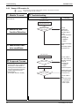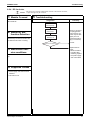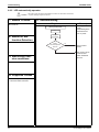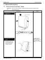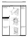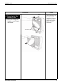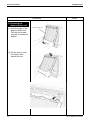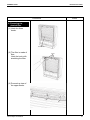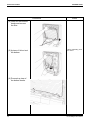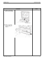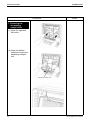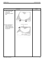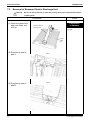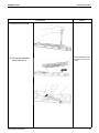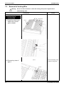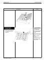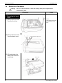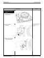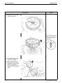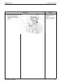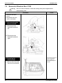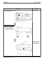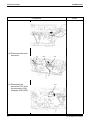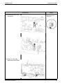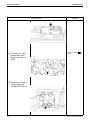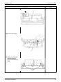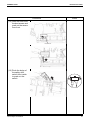
1
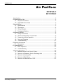
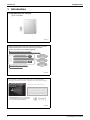
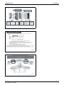
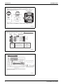
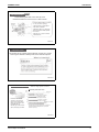
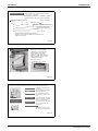
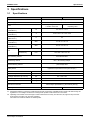
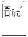
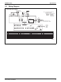
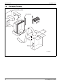
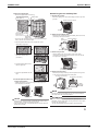
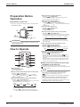
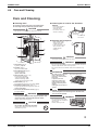
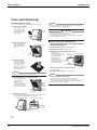
SiENBE81-623A
Service
Manual
Photocatalytic Air Purifiers
SiENBE81-623A
Air Purifiers
MC707VM-S
MC707VM-W
1.Introduction ......................................................................................................2
2.Precautions for Use..........................................................................................8
2.1 Required Conditions ............................................................................8
2.2 Applicable Room Area .........................................................................8
3.Specifications ...................................................................................................9
3.1 Specifications ......................................................................................9
3.2 Dimensions ........................................................................................10
3.3 Wiring Diagram ..................................................................................11
3.4 Packaging Drawing ............................................................................12
4.Operation Manual...........................................................................................13
4.1 Safety Precautions ............................................................................13
4.2 Names and Operation of each Part ...................................................14
4.3 Preparation before Operation ............................................................16
4.4 Care and Cleaning .............................................................................19
4.5 Troubleshooting .................................................................................27
5.Optional Accessories .....................................................................................28
5.1 Dimensions ........................................................................................28
6.Troubleshooting .............................................................................................29
6.1 Basic Inspection ................................................................................29
6.2 Troubleshooting .................................................................................30
7.Removal Procedure .......................................................................................35
7.1 Removal of the Front Panel / Filters ..................................................35
7.2 Removal of Streamer Electric Discharge Unit ...................................44
7.3 Removal of lonizing Wire ...................................................................46
7.4 Removal of Fan Motor .......................................................................48
7.5 Removal of Electrical Box / PCB .......................................................52
Photocatalytic Air Purifiers
1
Introduction
SiENBE81-623A
1. Introduction
Photocatalytic Air Purifier
flash streamer
06CJG-2
Daikin's original electro-discharge streamer technology is used for
powerful decomposition and removal efficiency in the flash
streamer air purifiers we are marketing globally.
Totally differentiated from the competition,
our technology and performance are available nowhere else.
World’s
first
World’s
first
World’s
first
Flash streamer
NEW
Titanium Apatite Photocatalytic Filter
Bio-antibody filter
NEW
Allergen
Allergen
total
total removal
removal
Powerful
Powerful
deodorizing
deodorizing
Powerful
bacteria removal
Air purifier with renewed design for
performance and beauty.
06CJG-3
Flash streamer is the electro-discharge used in our air purifier that
decomposes (oxidizes) more than 1,000 times more than glow discharge*.
Streamer discharge
Area high-speed electrons
are generated
What is Flash Streamer?
Flash Streamer is a unique
technology developed by Daikin.
The Flash Streamer releases
streams of high-speed electrons
with strong oxidation power.
*Glow discharge: The most common type
of plasma that is used by a plasma ionizer,
etc., for electrostatic dust collection.
06CJG-4
2
Photocatalytic Air Purifiers
SiENBE81-623A
Introduction
NEW
Daikin original
Flash streamer
discharge unit
NEW
Prefilter
Bio-antibody
(with
filter
catechin)
Plasma
ionizer
NEW
Streamer space
NEW
Titanium
Electrostatic
Streamer
Apatite
dust
deodorizing
Photocatalytic
collection
catalyst
Filter
filter
06CJG-5
Decomposition is continuous
Formaldehyde
concentration
in room (ppm)
When formaldehyde’s concentration of 0.2*2 ppmis continually emanated
Operation start
*2
Without Flash streamer
*1
With Flash streamer
Running time (mins.)
Test conditions: Air flow: 420m3/h.; Test room: approx. 9.6 m2
(Compliant with Ministry of Land, Infrastructure and Transport (Japan) guideline.*)
*Tentative WG guideline based on Ministry of Land, Infrastructureand Transport (Japan)
sick house evaluation method.
*2 0.2 ppm = average of amount of formaldehyde released in
newly built home and formaldehyde released from furniture, etc.
Differing from transitory pollutants such as cigarette smoke, the removal of formaldehyde is considered
more difficult because it continually emanates. Flash streamer makes removal possible.
06CJG-6
With
WithTitanium
TitaniumApatite
ApatitePhotocatalytic
PhotocatalyticFilter,
Filter,
Flash
Flashstreamer,
streamer,
and
andBio-antibody
Bio-antibody filter,
filter,
Mites
Pollen
Mold
and others
Removal
al
of
allergens
Powerful
deodorizing
Allergen
total removal
Removal of
Diesel exhaust
adjuvants
ad
particles
Exhaust gas
VOC
and others
Powerful
bacteria removal
06CJG-7
Photocatalytic Air Purifiers
3
Introduction
SiENBE81-623A
Adjuvants are substances included in air pollutants such as
exhaust gas that, when inhaled along with allergens, make one's
allergy symptoms worsen.
Allergy symptoms
worsen.
Adjuvant
Allergens
Adjuvant
Mites
Pollen
Mold
and others
Diesel
Diesel exhaust(DPE)
exhaust(DPE)
Diesel exhaust
particles
Exhaust gas
(NOx, formaldehyde,
etc.)
VOC
(toluene,xylene, etc.)
and others
Allergens
Pollen
Only flash streamer removes adjuvants.
06CJG-8
Powerfully breaks down odors in 3 stages!
Odor
molecules
Electrostatic dust
collection filter
Purified air
Plasma
ionizer
deodorizing efficiency
efficiency
95%% deodorizing
Flash
streamer
Flash streamer
X
Titanium Apatite
Photocatalytic Filter
Flash streamer
X
Streamer
deodorizing
catalyst
06CJG-9
Disinfection
Titanium Apatite
Photocatalyst
Almost all
removed
after 24 hrs.
The Flash Streamer
further activates the
photocatalyst!
06CJG-10
4
Photocatalytic Air Purifiers
SiENBE81-623A
Introduction
NEW
Bio-Antibody Filter
The Bio-Antibody filter works in the same way as the
influenza vaccination. It removes viruses in about 1 minute.
• The Bio-Antibody filter is usable
for one year after opening.
• Replacement for subsequent
years will be available.
• Operation will not be adversely
affected if the Bio-Antibody filter
is not used.
• Effective for 3 years from date
of manufacture.
06CJG-11
Catechin Pre-Filter
The pre-filter not only catches large dust particles, pet hairs, etc., but also
removes germs attached to them by means of the catechincomponent.
What is Catechin?
06CJG-12
Purifies with large air flow
Guideline purification times
High power
420m /h.
3
Powerful 4-directional
suction is used to reach
every corner of the room.
Odors, dust, bacteria and
formaldehyde are
relentlessly sucked in from
above, left, right, and front.
420m3/h. high-power suction!
Area
(m2)
Time (min.)
7
Purified in 7minutes
Suction of room air takes about 2.5 minutes.
9
Purified in 8 minutes
Suction of room air takes about 3 minutes.
13
Purified in 10 minutes
Suction of room air takes about 4 minutes.
23
Purified in 17 minutes
Suction of room air takes about 7.5 minutes.
(Results based on testing carried out in accordance
with Japan Electrical Manufacturers Association
JEM1467 standard.)
06CJG-13
Photocatalytic Air Purifiers
5
Introduction
SiENBE81-623A
Designed to be quiet A mere 31 dB even in M mode (standard mode).
It's as quiet as a whisper.
Top-ranking silent operation is achieved by Daikin's
original shroud fan and a low-pressure-loss filter.
Operation sound and air flow
Operation sound (dB)
Airflow
(m3/h)
Quiet Low noise
16 dB in LL mode
60
Noise level of 40 dB is that of a library.
24 dB in L mode
120
With this air purifier silence
is kept even in standard mode!
31 dB in M mode
180
38 dB in H mode
285
Operation sound is kept below 47dB even at maximum air flow
of 420 m3/h. (HH mode).
06CJG-14
7-year pleated filter
Comes with 7 pleated filters
Operation is economical since
the air purifier comes with 7
filters. You won't need to buy
filters for 7 years. Also, since the
filter is replaced each year, filter
efficiency will not drop.
Easy filter storage!
Unused filters can be stowed
neatly inside the unit.
06CJG-15
Control the numerous features with the easy-to-use remote control.
Antitamper lock
It prevents small children from
mishandling.
TURBO mode
This convenient mode provides
high-power operation.
Off timer
The remote control can be set
to turn off the unit after 1, 2 or 4
hours.
Pollen mode
By creating a gentle turbulence
in the room air, pollen is caught
before it lands on the floor.
Negative ions
The large air flow fills the entire
room, corner to corner, with
freshened air.
Remote control
storage space
The remote control stores
neatly in the top of the unit.
Display adjustment
The brightness of lamps on the
indicator panel can be adjusted.
06CJG-16
6
Photocatalytic Air Purifiers
SiENBE81-623A
Introduction
Flat panel blends with interiors and is easy to clean.
Quick-wipe panel
Designed for easy
maintenance, a single
wipe with a wet cloth is all
it takes to keep it clean.
06CJG-17
Photocatalytic Air Purifiers
7
Precautions for Use
SiENBE81-623A
2. Precautions for Use
2.1
Required Conditions
!Ambient Temperature/Humidity
Use this product under the following conditions.
Operating conditions
Room temperature
0°C - 32°C
Room humidity
80% or less
Use under other conditions may cause malfunction.
!Miscellaneous
•This product is for home use. Do not use for special purpose.
•This product is for indoor use only. Do not use in bathroom or outdoors as it is not water/condensation proof.
•Do not modify this product.
2.2
Applicable Room Area
MC707VM-S
MC707VM-W
House
less than 48m2
JEM1467
8
Photocatalytic Air Purifiers
SiENBE81-623A
Specifications
3. Specifications
3.1
Specifications
Model
MC707VM-S
Type
MC707VM-W
Photocatalytic air purifier
1φ 220-240 / 220-230V 50 / 60Hz
Power supply
Sparkling silver
+ metallic ocean blue
Color
White
+ Sparkling silver
Rated power consumption
(HH/H/M/L/LL)
W
55 / 23 / 14 / 10 / 8
Running current
(HH/H/M/L/LL)
A
0.48 / 0.22 / 0.14 / 0.10 / 0.08
Deodorizing Efficiency
(JEM1467"1)
%
95
Operating sound "2
(HH/H/M/L/LL)
dBA
47 / 38 / 31 / 24 / 16
Sound power "2
(HH/H/M/L/LL)
dBA
62 / 52 / 40 / 39 / 31
Type
Fan
Air flow rate
(HH/H/M/L/LL)
Multi blade fan (Sirocco fan with shroud assembly)
m3/h
Plasma ionizer (Electrostatic dust collection) + Electrostatic
dust collection filter
Dust collecting method
Flash streamer + Titanium apatite photocatalytic
filter + Deodorizing catalyst
Deodorizing method
Bio-antibody filter + Flash streamer + Titanium apatite
photocatalytic filter
Bacteria filtering method
Safety switch
(Operation stops when the front panel is open.)
Safety device
Power cord
420 / 285 / 180 / 120 / 60
m
2.0
Dimensions (H x W x D)
mm
533 x 425 x 213
Package dimensions (H x W x D)
mm
587 x 478 x 263
Product weight
kg
8.7
Gross weight
kg
11.0
Standard accessories
Drawing number
Operation manual (1), Wireless remote control (1),
Photocatalytic pleated filter (7), Bio-antibody filter (1)
3D051236
3D051237
NOTE:
"1. Deodorizing efficiency means the combined removal rate of ammonia, acetaldehyde and acetic acid after burning five
cigarettes in a 1m3 airtight container and running the air purifier at rated air flow for one minute.
"2. Operating sound levels are the average of values measured at 1m away from the front, left, right and top of the unit.
(This equal to the value in an anechoic chamber.)
The values are measured without bio-antibody filter.
Photocatalytic Air Purifiers
9
Specifications
3.2
SiENBE81-623A
Dimensions
· Required installation space
Signal Transmitter
11
8
90
Air outlet grille
100.or more
MC707VM-S, MC707VM-W
500. or more
1000.or more
500. or more
52
• Dimension of remote controller
Air inlet grille
1000. or more
(ARC437A3)
Handles
533
Air inlet grille
Manufacturer's Label
1
1.3
425
2
4
1.3
213
11
Power supply cord
Approx. 2.0m
3D050511
10
Photocatalytic Air Purifiers
SiENBE81-623A
3.3
Specifications
Wiring Diagram
MC707VM-S, MC707VM-W
IONIZATION PART
/STREAMER PART
GRN
A2P
BLK
GRN
M1F
A4P
NEGATIVE ION
GENERATION PART
6 1
RED WHT
CN1
6
A1P
S1
RED
S2
6 1
7
4 3 2 1
4
10
10
DC 340V OUT PS
DC 15V OUT
DC 12V OUT
AC IN
DC 5V OUT
GND
S11
1
1
S127
1
20
3
3
Z1C
BLK
F1U
N=3
BLK
1
S8
2
BLU
BRN
POWER SUPPLY PLUG
220-240V/220-230V 50/60Hz
1
20
A3P
LED8 LED9 LED10 LED11 LED12
1
20
H1O
K1A
A1P
A2P
A3P
A4P
F1U
M1F
BS1
BLU ORG
BRN WHT
K1A
S401
10
H8P
Note : 1.S,CN SHOWS A CONNECTOR
2.BS SHOWS A SWITCH.
3.SYMBOLS SHOWS AS FOLLOWS.
RED:RED
BLK:BLACK
WHT:WHITE YLW:YELLOW
GRN:GREEN BLU:BLUE
PNK:PINK
BRN:BROWN
ORG:ORANGE
MS
H9P
S128
H1O
H10P H11P H12P
LED1 LED2 LED3 LED4 LED5
LED6
LED7
LED16
LED13 LED14 LED15 LED18 LED19
H1P
H6P
H7P
H16P
H13P H14P
H2P
H3P
BUZZER
SAFETY SWITCH
PRINTED CIRCUIT BOARD (FOR POWER SUPPLY & CONTROL)
PRINTED CIRCUIT BOARD (FOR HIGH VOLTAGE POWER SUPPLY UNIT)
PRINTED CIRCUIT BOARD (FOR DISPLAY)
DUST SENSOR
FUSE (250V, 3.15A)
FAN MOTOR
MAIN SWITCH
H4P
BS2
H1P
H2P
H3P
H4P
H5P
H6P
H7P
H8P
H5P
FILTER RESET SWITCH
LED (AUTO OPERATION:YELLOW)
LED (LL:GREEN
LED (L :GREEN)
LED (M :GREEN)
LED (H :GREEN)
LED (TURBO:GREEN)
LED (POLLEN:GREEN)
LED (DUST SIGN:RED)
H15P H18P H19P
H9P
H10P
)H11P
H12P
H13P
H14P
H15P
H16P
H17P
ODOR
SIGNAL
SENSOR RECEIVER
REMOTE
CONTROL
LED17
BS2
H17P
BS1
LED (DUST SIGN:YELLOW)
H18P LED(CLEANING OF IONIZATION PART:RED)
LED (SIGN:GREEN)
H19P LED (FILTER REPLACEMENT:RED)
LED (ODOR SIGN:YELLOW)
Z1C FERRITE CORE
LED (ODOR SIGN:RED)
LED (STOP TIMER(1 HOUR):YELLOW)
LED (STOP TIMER(2 HOUR):YELLOW)
LED (STOP TIMER(4 HOUR):YELLOW)
LED (NEGATIVE ION:GREEN)
LED (ANTITAMPER LOCK:ORANGE)
3D050510
Photocatalytic Air Purifiers
11
Specifications
3.4
SiENBE81-623A
Packaging Drawing
Packed Filter (Bio-Antibody)
Filter (Pleated)
Accessory kit
Warranty
C: 3P165820A
12
Photocatalytic Air Purifiers
SiENBE81-623A
Operation Manual
4. Operation Manual
4.1
Safety Precautions
Safety Precautions
• Keep this manual where the operator can easily find them.
• Read this manual attentively before starting up the unit.
• For the reason of safety the operator must read the following
cautions carefully.
• Do not use outdoors or where exposed to direct sunlight.
Direct sunlight can weaken remote control signal reception
sensitivity and discolor the casing.
• Do not use near to sources of heat such as heaters.
• This manual classifies precautions into WARNING and CAUTION.
Be sure to follow all precautions below: they are all important for
ensuring safety.
Heat can discolor and deform the casing.
• Keep the unit and remote control minimum 2m from
WARNING
If you do not follow these instructions exactly, the unit may cause
property damage, personal injury or loss of life.
CAUTION
If you do not follow these instructions exactly, the unit may cause minor
or moderate property damage or personal injury.
Never do.
Be sure to follow the
instructions.
Never touch the air purifier
(including the remote
control) with a wet hand.
Never cause the air purifier
(including the remote
control) to get wet.
•
•
•
•
lighting, TVs, radios, stereos and aerials.
This unit can disturb TV pictures and generate interference.
Illumination can weaken remote control signal reception
sensitivity and discolor the casing.
Do not use in the place of kitchen fans or cooker hood fans.
Adverse conditions of use can shorten service-life of the
prelilter and ion filter, as well as lead to equipment damage.
Prevent combustibles (hair sprays, etc.), sparks and
incenfrom being drawn into the unit.
Such substances can cause fire.
Do not insert fingers or foreign objects into the inlet or
outlet openings.
Electric shock or damage may occur.
There exists a danger of hands getting caught in the motor and
causing injury.
The appliance is not intended for use by young children or
pets without supervision.
• Young children or pets should be supervised to ensure
that they do not play with the appliance.
• When using pesticides of an indoor fumigation type (fume
• Do not use the power cable if it is damaged.
Using a damaged power cable is extremely hazardous; if the
power cord becomes damaged, you must obtain a replacement
from the manufacturer or from a properly-authorized service
agent. Do not attempt replacement yourself.
• Do not disassemble, remodel or attempt to service this
equipment.
Unwarranted tampering can lead to fire and/or malfunction.
• Do not operate with wet hands.
Electric shock may occur.
• Do not use power supplies other than the rated supplies
Fire or electric shock may occur.
•
•
•
• Do not damage the electrical power cord, construct
•
•
•
•
•
anything, or forcibly bend, stretch or twist the cord.
Do not set heavy items on the cord or place the cord
between items.
If the electrical power cord is damaged, fire or electric shock may occur.
Before changing filters, cleaning the equipment or moving
it, turn it OFF and unplug the power cable.
Working with power ON can lead to fire and/or electric shock.
Do not use the power cable if damaged or loose in the socket.
Using the power cable in anything but proper working
condition can lead to short-circuits and subsequently electric
shock and/or fire.
Do not use in humid places or places which might be wet,
such as bathrooms.
Contact with water can lead to electric shock or damage the
equipment.
Do not use where oil components, such as machine oil,
are floating around.
There is the danger of cracking, electric shock or combustion.
Do not wet the air outlet or the main unit.
It may cause fire or electric shock.
• Do not use in locations where there is a large amount
fsoot, such as a kitchen or locations where there
combustible gas, corrosive gas or metallic dust is
present.
Fire or malfunction may occur.
CAUTION
•
•
•
•
release), stop the operation of the air purifier to none of the
chemical is sucked inside the unit.
The chemical components will accumulate inside the
unitdepending on your physical condition, you may react to the
irritation which is bad for your health.
When used in conjunction with a humidifier, keep mist from
being directly drawn into the unit.
Mists can lead to electric shock and/or equipment damage.
Do not block the intake or outlet.
Blocked openings can reduce capacity (air will not be cleaned
throughout the entire room) and/or damage the equipment.
Do not place any containers which hold water such as
goldfish bowls or flower vases on or close to the unit.
If water gets inside the unit, electric shock or malfunction may
occur.
Do not wipe with benzine or thinner, or spray with
insecticide.
Such substances can cause cracking, electric shock and/or fire.
If not using the unit for long periods of time, unplug the power cable.
Dielectric breakdown can lead to leakage current and subsequently
electrical shock and or short-circuit may occur causing a fire.
If the power plug is unplugged, be sure to hold and pull out
the end of the power plug without holding the power cord.
There is a chance that an electrical short or short-circuit may
occur causing a fire.
Do not operate with a pre-filter or filter removed.
Malfunction may occur.
• Do not sit on, stand on or shake the unit.
Malfunction may occur.
• Do not use when the unit is on its side or leaning.
Malfunction may occur.
• When using another burner at the same time, actively
ventilate the area.
This unit cannot remove carbon monoxide.
If the ventilation is not sufficient, carbon monoxide poisoning
may occur.
Toxic substances such as cigarettes (carbon monoxide) cannot be
removed.
• Do not use close to lighting equipment (within 1m).
The reception sensitivity of the remote control may be
reduced and the color may change.
2
Photocatalytic Air Purifiers
13
Operation Manual
4.2
SiENBE81-623A
Names and Operation of each Part
Names and Operation of each Part
Main unit
Front
6 4
8
Shock-absorbing
material (cardboard)
13
12
3
5
Be sure to remove the
shock-absorbing material
before operating. (page 5.)
10
11
2
Pleated filter
Rear
16
14
15
17
18
19
19
14
7
9
1
20
1 Front panel
14 Air inlet
2 Main unit display (page 4.)
15 Remote control storage slot
Shows operation status.
3 Pre-filter (green)
Removes comparatively large material and dust.
Stores the accessory remote control.
16 Handle
Use when moving the main unit.
4 Plasma ionizer
17 Air outlet
5 Bio-antibody filter (white)
18 Negative ionization assembly
Absorbs viruses.
6 Ionizing frame
7 Ionized wire
Small dust particles which are not captured by the pre-filter are
positively charged to that they can be more easily absorbed by the
negatively-charged pleated filter.
8 Streamer discharger
9 Opposing pole plates
Generates negative ions. Functions to combine positively charged
toxic substances in a room and neutralize and transform them.
• If static electricity is applied, the amount of negative ions
generated will be temporarily reduced.
19 Power supply cord hook
Winds the power supply cord when storing the main unit.
Do not wind the cord during operation.
20 Power supply cord
10 Pleated filter (front: white, back: blue)
Absorbs dust particles using the principle of static electricity.
11 Deodorizing catalyst (black)
Absorbs and decomposes elements which could not be removed
before returning the air back to the room.
Note: cannot be washed with water.
12 Filter container
Six replacement pleated filters are included.
13 Ventilation fan
3
14
Photocatalytic Air Purifiers
SiENBE81-623A
Operation Manual
Main unit display
1
2
4
3
5
13
6
Air is taken in from here and the dust sensor detects the dirty state
of the air.
2 Clean monitor (Dust)
Detects the dirty state of the air and indicates the results.
Indicator
8
9
10
11
12
14
4 Automatic operation indicator (yellow)
1 Air intake for dust sensor
Dust
7
15
Off
On
Green
Low
Lit during automatic operation.
5 Airflow rate indicator (green) (page 7.)
Lit by the set airflow rate setting.(The air volume lamp is on during
automatic or manual operation.)
6 Turbo mode indicator (green) (page 7.)
Lit during turbo mode.
7 Anti-pollen mode indicator (page 7.)
Lit during pollen mode.
Yellow
Green
8 Negative ion mode indicator (page 7.)
Indicates during negative ion operation.
Red
Yellow
Green
High
• In the following case, only the green light is on for the first
7 seconds regardless of pollution from the air.
• Operation directly after setting the front panel or plasma ionizer
• Operation directly after inserting the power plug
• You can change sensitivity setting of the dust sensor lamp.
3 Clean monitor (Odor)
Detects changes to odors and indicates the results.
Odor
Indicator
Off
9 OFF timer setting indicator (yellow) (page 7.)
Indicates the set OFF timer time.Indicates the remaining time after
setting as the time passes.
10 Clean indicator (red) (pages 11, 12.)
The lamp will blink for cleaning time of the plasma ionizer.
11 Replace indicator (red) / Reset button
The lamp will be on for replacement time of the pleated filter and
blink after certain time has elapsed from the turning on.*Press the
reset button after replacement. (page 10.)
12 Lock lamp (page 7.)
On
Green
Lit during lock.
13 Air intake for odor sensor
Air is taken in from here and the odor sensor detects the odor state.
Weak
14 Receiver
Green
Receives signals from the remote control.
Yellow
15 Operation switch / stop button
Green
Yellow
Red
Each time this button is pressed, the operation mode switches as
shown below.
Strong
• Reactions to sudden temperature/humidity changes and odorless
gas (carbon monoxide) may occur.
• There may not be any reaction for a uniform case without any
changes to the intensity of the odor.
• There may be no reaction to pet odors or garlic odors.
• Different people have different sensitivity to odors so you may not
notice an odor even though the lamp is green.
• In the following case, only the green light is on for the first
1 minute and this state is regarded as the reference value of the
odor sensor.
• Operation directly after setting the front panel or plasma ionizer
• Operation directly after inserting the power plug
“ ”
(Automatic)
“
”
LL (Quiet)
“ ”
L (Low)
“ ”
M (Standard)
(Stop)
“
”
(Pollen)
“ ”
HH (Turbo)
“ ”
H (High)
* During automatic operation the airflow rate at that time will also be
lit.
4
Photocatalytic Air Purifiers
15
Operation Manual
4.3
SiENBE81-623A
Preparation before Operation
Preparation Before Operation
Remote control setup
Remote control
• Do not drop or place the remote control in water.
1. Remote control
preparations
(Damage may occur.)
• Do not press the remote control buttons with sharp objects.
• Battery is already set in the remote
control but the remote control
cannot be used as is without first
preparing it.
Use the remote control after
pulling out the clear sheet from the
battery cover.
(Damage may occur.)
• The signals may not be received well of electronic lighting style
fluorescent lamps (such as inverter fluorescent lamps) are in the
same room. For these cases, discuss with the dealer.
• If other electrical device operate by the remote control, either
separate them from the remote control or discuss with the dealer.
Attaching the pleated filter
2. Remote control storage
WARNING
• When the remote control is not being
used, you can store it in the remote
control storage slot.
Set the filter while the power supply plug is not plugged in.
CAUTION
• The unit must be operated with a pre-filter.
If they are not set and the unit is operated, malfunctions may occur.
3. Using the remote control
• Point the transmitter of the remote
control towards the receiver of the
main unit.
If an obstruction to the signal, such
as a curtain, exists, the remote
control will not operate.
• The distance from which the
remote control can transmit is
approximately 6m.
1. Remove the front panel.
• Place your fingers in the indentations on the bottom of the unit
and pull forward, holding on to the bottom of the panel.
Front panel
Receiver
4. Battery replacement
1) Open the cover on the rear of the
remote control towards the
arrow.
2) Replace the battery with CR2025
battery.
(Be sure to set the battery with
the + side of the cover as shown
in the figure.)
3) Close the cover to its original
position.
NOTE
CAUTION
• Do this before plugging the unit into a power supply.
• Always install the pleated filter before running the unit.
2. Remove the shock-absorbing material and then remove
the plasma ionizer.
1) Remove the shock-absorbing material.
• Store the batteries where babies and children cannot reach them.
If, by chance, a battery is swallowed, be sure to contact a doctor
immediately.
• When discarding batteries, cover the terminals of the batteries with
tape.
If mixed with other metal or batteries, heat, explosion or combustion
may occur.
Shock-absorbing
material (cardboard)
ATTENTION
Battery
• The included coin type battery is prepared for initial use.
They will be consumed within 1 year from the manufacturing date of
the air purifier.
• A replacement target is approximately 1 year but if the reception
becomes difficult, replace the batteries with new coin type battery
CR2025.
• Coin type battery close to the “recommended usage period” may
need to be replaced soon.
• In order to prevent malfunctions or injuries due to leaking or
explosions, be sure to remove the coin type battery when the unit
will not be used for a long period of time.
2) Holding the handle, lift towards yourself and remove from the top
2 hooks.
Plasma ionizer
Hooks
(one left and one right)
5
16
Photocatalytic Air Purifiers
SiENBE81-623A
Operation Manual
! Attaching the bio-antibody filter
3. Attach the pleated filter.
• Remove the pleated filter from the bag.
The side with the three
holes goes up
1. Remove the pre-filter.
Pleated filter
• Remove by pulling out in front while holding the tabs on top of the
pre-filter.
1)
Pull out in front to remove.
3)
3)
2)
4)
2)
The white side should
be facing you.
Deodorizing
Securing tape
catalyst unit
• Hook on the top and bottom hooks, insert into the left and right
hooks, and then secure with the tape.
Pre-filter
2. Attach the bio-antibody filter.
• Hook the holes (2 locations) of the bio-antibody filter on the hooks
(2 locations) of the plasma ionizer.
Top hooks (2 locations)
Holes
(2 locations)
1) Place the pleated filter holes on the 3 upper tabs of the
deodorizing catalyst unit.
Bio-antibody filter
3. Restore the pre-filter.
2) Hook the holes of the pleated
filter on the bottom hooks.
(2 locations)
• Hook the bottom part of the pre-filter on the bottom hooks
(2 locations) of the plasma ionizer and then insert it into the left
and right hooks (4 locations).
Left and
right
hooks
(4 locations)
3) Insert the pleated filter into the
left and right hooks.
Plasma
ionizer
Hooks
(2 locations)
4) Secure the pleated filter with the
tape.
4. Restore the front panel.
• Hook the top hooks (3 locations) of the front panel on the grooves
on top of the main unit and then close the panel.
Top hooks (3 locations)
Top grooves (3 locations)
4. Install the plasma ionizer in its
original configuration.
• Holding the handle, snap onto the 2 upper hooks and push in.
• Insert the plasma ionizer fully.
Hook
Pre-filter
Overhead view
Front panel
NOTE
• Securely close the panel. Failing to do so may cause activation of
the safety switch and out of unit operation.
Plasma ionizer
NOTE
• Only run the unit with the pre-filter and pleated filter in place. If they
are not in place, running the machine may break it.
• If the front and blue sides of the pleated filter are reversed, the unit’s
performance will suffer.
ATTENTION
• The bio-antibody filter is a dedicated filter to speed up virus
elimination. Use it in winter when air is dry and virus is easy to grow.
Change and storage (page 9.)
*The air cleaning effect remains regardless of the attachment.
6
Photocatalytic Air Purifiers
17
Operation Manual
SiENBE81-623A
4 When you want to quickly clean the air
Preparation Before
Operation
Press the “
” [TURBO] button.
• A high airflow rate will quickly remove any dirtiness in the air.
• This is convenient to use when cleaning.
5 When you want to remove pollen
! Installation of main unit
To install the unit, comply with the following standards to ensure performance.
<If installed on a table>
Press the “
” [ANTI-POLLEN] button.
• Switching the airflow speed every 5 minutes between
“
” M (Standard) and “ ” L (Low) will catch pollen before they
fall on the floor.
6 When you expel negative ions
Min. 100cm
Press the “
” [RELAX] button.
Pressing again will cancel.
• Generates negative ions.
Airflow
7 When you want to decide a time to stop operation
Press the “
” [OFF TIMER] button.
• Each time it is pressed the timer setting switches as shown below.
The remaining time will be lit in the “OFF timer setting indicator”.
Min. 10cm
Min. 50cm
“ 1 ” (1 hour)
Min. 50cm
ATTENTION
• If operated outside the conditions shown below, malfunction may occur. .
• Indoor temperature 0-32°C
• Indoor humidity 80% or less
“ 2 ” (2 hour)
“ 4 ” (4 hour)
(Cancel)
• When the set time is reached, the operation will automatically
stop.
• The set time can be changed if the button is pressed while the
timer is operating.
8 When you want to change the brightness of the
operation lamp and clean monitors
Press the “
” [BRIGHTNESS] button.
• Each time it is pressed, the display will switch as shown below.
(Dark)
How to Operate
(Off)
(Standard)
9 When you want to prevent incorrect operation
9
1
2
3
4
5
6
8
7
Press the [ON/OFF] button.
Pressing again will stop.
NOTE
2 When you want to automatically switch the airflow rate
Press the “
” [AUTO] button.
• Automatically adjusts the airflow rate to “
” LL (Quiet),
“
” L (Low), “ ” M (Standard), “ ” H (high) in response to
the dirty condition of the air.
3 When you want to manually switch the airflow rate
Press the “
” [FANSPEED] button.
• Each time it is pressed the airflow rate switches as shown below
allowing you to choose your desired flow.
”
LL (Quiet)
! When you want to operate the unit using
the button on the main unit
When the remote control is not in your hand, you can use the
“
” [Operation Switch / Stop] button on the main unit without using the
remote control. (page 4.)
1 When operating
“
Press the “
” [LOCK] button for 2 seconds.
Pressing again for 2 seconds will cancel.
• Stops the function of the button other than the “
” [LOCK]
button on the main unit and buttons on the remote control.
• This makes it possible to prevent children from operating the unit
incorrectly.
• When you want to release the child lock settings and the remote
controller is not in your hand, remove the power plug once and
then reinsert it and operate the unit.
“
”
L (Low)
“ ”
“ ”
M (Standard)
H (High)
• The unit will not operate for 3 seconds after the front panel or
plasma ionizer is set or power plug is inserted even though
“
” button on the remote control is pressed.
• Operation will stop for safety when the front panel is opened during
operation.
• When an incorrect operation is performed during operation
If the main unit display is abnormally on or remote control is
disabled due to thunder or radio transmission during operation, pull
the power plug and then re-insert it after 3 seconds.
• The setting “
” LL (Quiet) is a very slow airflow rate and is
convenient when sleeping.
• After setting “
” LL (Quite) the power for cleaning the air
decresases because of the operation at slow airflow rate.
7
18
Photocatalytic Air Purifiers
SiENBE81-623A
4.4
Operation Manual
Care and Cleaning
Care and Cleaning
Cleaning chart
Cleaning the air inlet for the dust/odor
sensor
For cleaning, remove each part in the number order.
For restoring each part, follow the opposite order.
• Clean dusts clogged in
the air inlet for the
dust/odor sensor.
• Use crevice nozzle of a
cleaner for cleaning.
CAUTION
• Stop operation and pull the power plug before cleaning.
Air inlet for the
dust sensor
Air inlet for the
odor sensor
1
4
2
5
Cleaning the front panel
• Wipe off the dirt with a
cloth or tissue slightly
soaked with water.
• In the case of heavy dirt,
wipe it off with a cloth
soaked with mild
detergent.
6
3
CAUTION
• Do not use hard sponge. Scratch may result.
7
WARNING
1 Front panel (page 8.)
• Do not use gasoline, benzene, thinner, polishing powder, keroseneor
If gets dirty; wipe off
alcohol. Crack, electric shock or fire may result.
• Do not rinse the main unit. Electric shock, fire or breakdown may
2 Pre-filter (page 9.)
result.
Once in two weeks; clean
3 Bio-antibody filter (page 9.)
1 year after opening;
replace Unwashable
ATTENTION
• Be careful not to scratch the
4 Plasma ionizer (pages 11, 12.)
If the cleaning sign blinks;
• Opposing pole plate; soak
• Streamer discharger; soak
• Ionizing frame (Ionized wire); soak
5 Pleated filter (page 10.)
If the replacement sign turns on or blinks; replace
6 Deodorizing catalyst unit (page 15.)
If it gets dirty, without removing from the main unit;
vacuum Unwashable
7 Air inlet for the dust/odor sensor (page 8.)
If clogged; vacuum
WARNING
During maintenance you must stop the operation and
remove the power plug from the electrical outlet.
Electric shock or injury may occur.
CAUTION
Do not wash the main unit with water.
If water gets inside the unit, electric shock or
malfunction may occur.
front or damage the rear
protrusions of the removed
front panel.
In particular, the rear
protrusions function as a
safety switch to turn OFF
thpower if the front panel is
opened.
If damaged, the unit will not
operate.
Rear side of front panel
Protrusion
NOTE
If the front panel is not correctly set on the main unit,
the unit will not operate.
WARNING
• Do not touch the safety switch
on back of the hole on bottom of
the main unit.
Electric shock may result.
Bottom hole
8
Photocatalytic Air Purifiers
19
Operation Manual
SiENBE81-623A
Care and Cleaning
! Cleaning the pre-filter
NOTE
It is recommended to clean the pre-filter every two weeks.
• Securely close the panel. Failing to do so may cause activation of
1. Remove the front panel.
the safety switch and out of unit operation.
• Lay your finger to the
dent at bottom of the
main unit, hold bottom
part of the panel and
then pull it up.
Front
panel
CAUTION
• Do not dry at a location directly exposed to the sun.
• Do not clean with water hotter than 50°C.
• Do not burn with fire.Color changes or deformation may occur and
the unit may become unusable.
2. Remove the pre-filter.
• Remove by pulling out in
front while holding the
tabs on top of the prefilter.
Pull out in front to remove.
Replacing the bio-antibody filter
(The bio-antibody filter should be replaced
around once a year.)
1. Remove the front panel. (See the left figure.)
2. Remove the pre-filter. (See the left figure.)
3. Replace the bio-antibody filter with new one.
• Remove a used
bio-antibody filter from the
hooks (2 locations) on top
of the plasma ionizer.
• Hook the holes (2
locations) of a new
bio-antibody filter on the
hooks (2 locations) on top
of the plasma ionizer.
Pre-filter
3. Clean the pre-filter.
• After using a vacuum
cleaner to remove any
dust, clean with water.
• If it is very dirty, use a
soft brush or a neutral
cleaner to clean then dry
well in the shade.
Top hooks (2 locations)
Holes
(2 locations)
Bio-antibody filter
4. Install the pre-filter in its original position.
(See the left figure.)
5. Restore the front panel. (See the left figure.)
NOTE
• “Cleaning sign” may blink if any droplet remains.
NOTE
Replacing the bio-antibody filter
4. Install the pre-filter in its original position.
• Hook the bottom part of
the pre-filter on the
bottom hooks
(2 locations) of the
plasma ionizer and then
insert it into the left and
right hooks (4 locations).
Left and
right
hooks
(4 locations)
Hooks
(2 locations)
Contact your dealer for replacement bio-antibody filter.
Life of the bio-antibody filter is about 1 year after opening.
If you do not use the bio-antibody filter for a long time, store it away
from direct sunlight without opening.
Plasma
ionizer
5. Restore the front panel.
• Hook the top hooks (3 locations) of the front panel on the grooves
on top of the main unit and then close the panel.
Top hooks (3 locations)
Top grooves (3 locations)
Hook
Overhead view
Front panel
9
20
Photocatalytic Air Purifiers
SiENBE81-623A
Operation Manual
Replace a pleated filter
(Replace the pleated filter when the “replace indicator” on the
main unit display turns on or blinks.)
5) Insert the pleated filter into the
left and right hooks.
turn on
1. Remove the front panel. (page 9.)
2. Remove the plasma ionizer.
Holding the handle, lift towards yourself and remove from the top 2
hooks.
4. Restore the plasma ionizer and the front panel. (page 6.
5. Insert the power plug.
6. Press the reset switch on the main unit display.
Hooks
(one left and one right)
Plasma ionizer
Press the reset switch
with a sharp material
such as a tooth pick to
turn off the replacement
sign. (It will beep.)
3. Replace a pleated filter with new one.
1) Remove a used pleated filter.
• Remove a pleated filter from the tape at bottom of the
deodorization catalytic unit and then unhook the hooks
(3 locations on top and 2 locations on bottom).
Top hooks
(3 locations)
Deodorizing
catalyst unit
Pleated Filter
Bottom hooks
(2 locations)
Securing tape
2)Take out a new pleated filter (1 sheet) and then attach it to the
deodorization catalytic unit.
• Hook on top and bottom hooks, insert into left and right hooks
and then secure with the tape.
3)Place the pleated filter holes on the 3 upper tabs of the
deodorizing catalyst unit.
The side with the three holes goes up.
NOTE
Replace a pleated filter
Contact your dealer for replacement pleated filter.
It is not necessary to replace a pleated filter until the replacement
sign turns on or blinks. When the replacement sign turns on, replace
a filter even though it is not dirty.
* Apparent dirt is not proportional to filter performance.
The replacement timing of the pleated filter differs depending on
usage and installed place.
The replacement sign turns on after a year of everyday use in a
home where 10 cigarettes are smoked per day.
(The replacement timing will be shorten for use in a heavily air
polluted place.)
Remove the plasma ionizer
CAUTION
When cleaning be careful not to cut your hands on the ionizing line.
(Wearing rubber gloves is safer.)
1. Remove the front panel.
The white side should be facing you.
4) Hook the holes of the pleated
filter on the bottom hooks.
(2 locations)
• Lay your finger to the
dent at bottom of the
main unit, hold bottom
part of the panel and
then pull it up.
Front
panel
2. Remove the pre-filter.
(page 9.)
10
Photocatalytic Air Purifiers
21
Operation Manual
SiENBE81-623A
Care and Cleaning
3. Remove the bio-antibody filter.
Remove the bio-antibody filter from hooks (2 locations) at top of
the plasma ionizer.
Clean the plasma ionizer
(If “cleaning sign” on the main unit display blinks)
Top hooks (2 locations)
Blink
CAUTION
Stop operation before cleaning and be careful not to cut your hands
with the opposing pole plate or ionizer wires.
(It is safer to use rubber gloves.)
Bio-antibody filter
4. Remove the plasma ionizer.
• Holding the handle, lift towards yourself and remove from the top
2 hooks.
Plasma ionizer
1) Ionizing frame
3) Streamer discharger
Hooks
(one left and one right)
Plasma ionizer
5. Remove the opposing pole plates at back of the plasma
ionizer.
Open the knob of the ionizer frame and hold up the opposing pole
plate to remove.
Be careful not
to catch in the
internal ionizer
wires.
It is easier to
remove if lifted
from outside.
2) Ionized wire
4) Opposing pole plates
CAUTION
There are ionizer wires at back of the opposing pole
plate. When attaching or removing, be careful not to cut
them.
“Cleaning sign” blinks if operated while the ionizer wires are cut.
The dust elimination efficiency deteriorates while the sign is
blinking.
If the ionizer wires should be cut, replacement is necessary.
Contact your dealer.
Knob
Ionizing frame
Opposing
pole plate
Ionized wire
Open
6. Remove the streamer discharger.
• Insert your finger into the hole on top (hole with
then gently pull up the streamer discharger.
mark) and
Streamer discharger
11
22
Photocatalytic Air Purifiers
SiENBE81-623A
Operation Manual
Contents
Remove each part.
1) Ionizing frame
2) Ionized wire
(page 11.)
3) Streamer discharger
(page 11.)
4) Opposing pole plate
(page 11.)
Vacuum dusts on the
surface with a cleaner.
Vacuum
Caution
Do not remove the screws on the ionizer or streamer discharger. Breakdown may result.
Soak in water or warm
water with liquid mild
detergent. (about 1 hour)
Soak in water
with detergent
Clean off the dirt with a
cloth or soft brush.
Wipe off
Scrub down
Wipe off
Wipe the dirt off
(For detail, see page 13.)
(For detail, see page 13.)
Caution
Be sure to do in a shower-proof place such as bathroom or sink in a kitchen.
Use only specified volume of liquid mild detergent.
Do not use powder detergent or alkaline detergent and scrub with hard sponge.
Distortion or damage to the equipment may result.
Rinse with running water.
Rinse well
Soak in water or warm
water to remove
detergent.
(about 30 minutes)
Soak in water
or warm water
Caution
Soak well, as “cleaning sign” may be on even after cleaning if any detergent remains.
Rinse with running water
and then dry.
Rinse well
Caution
Be careful not to leave bits of tissue such as cloth. Malfunction may result.
Dry in the breezy shade.
(about 1 day)
Dry in the shade
Caution
Do not expose to direct sunlight. Resin part may be discolored or distorted.
Dry in the shade, as “cleaning sign” may be on even after cleaning if any moisture remains.
Attach each part.
(page 14.)
(page 14.)
(page 14.)
12
Photocatalytic Air Purifiers
23
Operation Manual
SiENBE81-623A
Care and Cleaning
CAUTION
When cleaning the unit, be careful not to cut your hands with the
opposing pole plate or ionizer wires.
(It is safer to use rubber gloves.)
When cleaning the unit, be careful not to cut the ionizer wires.
Be sure to do in a shower-proof place such as bathroom or sink in a
kitchen.
Use only specified volume of liquid mild detergent.
Do not use powder detergent or alkaline detergent and scrub with
hard sponge. Distortion or damage to the equipment may result.
1) Ionized wire
3) Ionizing frame
Clean off the resin part with a soft cloth.
Use a cotton bud to wipe off dirt of odd-shaped area where
your finger does not reach.
Be careful not to leave bits of tissue. Malfunction may result.
2) Streamer discharger
3) Ionizing frame
Cleaning the plasma ionizer
1) Ionized wire (8 pieces)
Clean off the ionizer wires and peripheral resin part with a soft
cloth.
Cotton bud
* Gently wipe off the ionizer wires.
Pulling hard may cut them.
* Use a cotton bud to wipe off dirt
of odd-shaped area.
2) Streamer discharger
Clean off the internal resin part with a soft cloth.
(For removal, see page 11.)
NOTE
If the ionizer wires are cut;
Replacement is necessary. Contact your dealer.
Discharge
needle
*2
: Resin part *1
*1 Wipe off only the resin part.
*2 Do not touch the discharge needle.
Bending the needle will reduce
deodorizing performance.
13
24
Photocatalytic Air Purifiers
SiENBE81-623A
Operation Manual
Assembling the plasma ionizer
2. Attach the streamer discharger.
1. Attach the opposing pole plates.
1) Securely insert the opposing pole plate into the hooks (2 locations
in the middle) of the plasma ionizer.
1) Insert bottom of the streamer discharger to the ionizer frame.
Insert downward
2) Attach the opposing pole plate while opening the knobs (one at a
side) of the plasma ionizer.
2) Insert top of the streamer discharger.
Open
3) Insert securely until it clicks.
3)Confirm if it is attached securely.
4) Attach another side of the opposing pole plate.
14
Photocatalytic Air Purifiers
25
Operation Manual
SiENBE81-623A
Care and Cleaning
Cleaning the deodorization catalytic unit
Vacuum dusts with a
cleaner without
removing from the
main unit.
(Do not wash.)
NOTE
If the operation of 4. is not performed, the unit will not return to
normal operation mode. If the operation of 4. is performed, during
the settings, the settings will not be correct.
When the sensitivity is set high, it will become difficult for the sensor
lamp to go out.
Optional accessories
For replacement pleated filter and bio-antibody filter, contact your
dealer.
Part name
Sensitivity settings of the dust sensor
The sensitivity of the sensor differs depending on the size of
room, installation place, and type of dirt.
Change the sensor sensitivity if you don’t like it.
” on the main unit for 10 seconds with the
1. Press “
remote control pointed at the main unit while holding
“
”.
The receiving tone sounds, one of “ ” L (Low),
“ ” M (Standard) and “ ” H (High) lamps blinks for 5 seconds,
and then the lamp corresponding to the set sensitivity turns on.
2. Change the settings using the “
Stop] button of the main unit.
” [Operation switch/
Switches each time it is pressed.
The settings is shown in the airflow rate indicator.
Airflow speed
display
“ ”
L (Low)
“ ”
M (Standard)
“ ”
H (High)
Dust sensor
sensitivity
High
(Sensor display
becomes easy
to light.)
Normal
(setting when
shipped)
Low
(Sensor display
will have difficulty
coming on.)
Part number
Pleated filter
(7 sheets)
KAC972A4E
Bio-antibody filter
(1 sheet)
KAF972A4E
If used with dirty parts;
Cannot obtain air clean effect.
Cannot obtain deodorization effect.
Odor may arise.
Disposal requirements
Your Daikin product is marked with this symbol. This
means that electrical and electronic products shall not
be mixed with unsorted household waste.
Disposal of this product must be done in accordance
with relevant local and national legislation. By disposing
of this product correctly, you will help ensure its proper
treatment, recovery and recycling, thus preventing
potential negative consequences for the environment and human
health. Please contact your local authority for more information.
Batteries must be removed from the remote control and disposed of
separately in accordance with relevant local and national legislation.
3. When you decide on the settings, point the remote
control at the main unit and press the “
”
[OFF TIMER] button.
The receive sound will beep and the setting lamp will flash.
4. Unplug the power plug one time and then after
3 seconds or more plug it in again.
This completes the settings.
Airflow rate indicator
Operation switch /
stop button
Off timer button
15
26
Photocatalytic Air Purifiers
SiENBE81-623A
4.5
Operation Manual
Troubleshooting
Frequently asked questions
Question
1. The dust sensor does not
change from the red (green)
lamp.
2. The sensitivity of the dust
sensor seems to be bad (or
too good).
3. Can I wash the
deodorization catalytic unit?
Is replacement necessary?
4. What to do if the ionizer
wires are cut?
5. Is not a problem to use
while the cleaning sign is
blinking?
Answer
This is due to dusts built up in the dust sensor.
Vacuum dusts from the air inlet with a crevice nozzle of a cleaner and then manually operate the unit for
a while. The sensor will go back to normal.
This is because react time of the dust sensor differs depending on the size of room.
If the unit is installed at the lower position of a room, reaction to smoke of cigarettes or others may be
bad. Re-install the unit at the higher place such as on a shelf. If the sensitivity is still bad, adjust the
sensor with sensitivity settings.
The deodorization catalytic unit cannot be washed.
(The unit will be ruined.)
Vacuum dusts with a cleaner without removing from the main unit. Replacement is not necessary.
If the ionizer wires should be cut, replacement is necessary.
Contact your dealer.
While the cleaning sign is blinking, electric dust collection and deodorization functions remarkably
deteriorate as electricity supply to the ionizer wires and streamer discharger stops for safety.
Be sure to inspect inside until the sign turns off.
(Blinking is not a problem from a safety viewpoint.)
Trouble Shooting
Investigate the problem once again before requesting repairs.
Case
Does not operate.
The four airflow rate displays, LL
(Quiet), L (Low), M (Standard) and H
(High) are flashing at the same time.
Check
Is the power plug unplugged?
Measure
Securely insert it.
Is the front panel correctly set?
Securely set it.
Are the battery of the remote control dead?
Replace with new battery. (page 5.)
Is there any foreign matter in the air outlet?
Remove the foreign matter.
For other cases, contact your dealer.
Is the unit installed at a location where the
flow does not pass or are there obstructions
close to the unit?
Remove the obstruction.
Is there too much dust in the pre-filter or
pleated filter?
Clean or replace. (pages 5, 6, 9)
Air does not come out.
Cleaning effect is not obtained.
Television screen is distorted.
Crackling, buzzing, and
fizzes sounds are audible
during operation.
Odor is coming from the air outlet.
The cleaning sign does not turn
off or blinks again even after
cleaning the plasma ionizer.
Is too much odors or smoke being generated?
For this case, contact your dealer.
Is a television or radio installed within 2m of
this unit or is an indoor antenna being used
close to this unit?
Separate the television, radio and indoor antenna from
this unit by 2m or more.
Is the power cord or antenna of the television
or radio close to this unit?
Separate the power cord and antenna of the television
or radio as much as possible away from this unit.
Is the plasma ionizer securely set?
Securely set it.
Is dust adhering to the ionizing line of the
plasma ionizer (resin part)?
Clean the plasma ionizer. (pages 11, 12.)
Has water entered into the spurt hole
moistening the negative ionization assembly?
The streamer discharger makes a fizzes
sound.
Is a large amount of odor being generated
temporarily? (Many people smoking or
grilling meat.)
If the negative ionization assembly is dry, the sound will
go away.
This is not abnormal.
If operated, the odor will gradually go away.
Have you moved the main unit to another room?
Odor from the original room may smell.
If the pre-filter or plasma ionizer dirty?
Clean it. (pages 9, 11, 12, 13.)
Is the plasma ionizer set securely?
Securely set it.
Are not droplets left in the opposing pole
plates or other places?
Wipe off droplets.
Are not bits of tissue left in the plasma ionizer?
Remove bits of tissue.
Did you rinse and soak the plasma ionizer
well after washing the plasma ionizer with
detergent?
Soak well.
Are not the ionizer wires cut?
Contact your dealer.
16
3P167171-1E
Photocatalytic Air Purifiers
27
Optional Accessories
SiENBE81-623A
5. Optional Accessories
5.1
Dimensions
5.1.1 Pleated Photocatalytic Filter
KAC972A4E
Specifications
Model
Item
Material
No. of packages
KAC972A4E
Non-woven fabric (electrostatic)
(Antibacterial and antiviral agent impregnated)
7
Notes: 1. Replacement guideline: Every year (for about 7
years in total)
2. Appearance color: White (front), blue (back)
338
100
12
130
260
C:3JHB10512
5.1.2 Bio-Antibody Filter
KAF972A4E
Specifications
Model
Item
Material
No. of packages
344
11
168
(b)
Bio-antibody filter
Model : KAF972A4E
Part
detail
6
Notes: 1. Replacement guideline: About 1 year (after
unpacking)
2. Appearance color: White
[Storage and handling precautions]
• If you do not use the filter soon, store it in a cool, dry place
that is not exposed to direct sunlight.
• The filter color density may become different for production
technique reasons. The performance is not affected.
• Unpack the filter just before use. (Otherwise the
performance may be affected or the quality degraded.)
• Dispose of the vinyl bag just after unpacking. Otherwise a
child may play with it (pulling it over his/her head, for
example), resulting in an accident.
• Keep the package out of children's reach.
• Dispose of a used filter as noncombustible waste. For
details, follow your local waste sorting rules and regulations.
288
325
6
KAF972A4E
Polyester/rayon non-woven fabric
(a) Filter
1
(b) Sheet
1
72
(a)
328
C:3JHB10513
28
Photocatalytic Air Purifiers
SiENBE81-623A
Troubleshooting
6. Troubleshooting
6.1
Basic Inspection
Good bye!
(1) Is the connector for the PCB plugged
in? Or is there any poor connection?
Where are
you going?
Connect firmly!
Broken!
Pulle
d ou
t!
(2) Is the wire harness broken?
!It is not malfunction
Red lamp is blinking.
Time for cleaning the
plasma ionizer.
Red lamp is on or blinking.
Replace the pleated filter and
press the reset button.
!Troubleshooting with Airflow Rate Indicator
The airflow rate indicators blink simultaneously.
The DC fan is locked.
Photocatalytic Air Purifiers
29
Troubleshooting
6.2
SiENBE81-623A
Troubleshooting
6.2.1 Equipment does not operate, or operation lamps does not light.
Caution
1
Be sure to turn off power switch before connect or disconnect connector,
or parts damage may be occurred.
Models Covered
5
Troubleshooting
Diagnosis
MC707VM-S
MC707VM-W
Is AC cord plugged in?
Or is breaker "ON"?
2
Plug in AC cord.
Set breaker to
“ON”.
No
Yes
Method of Malfunction Detection
Close the panel
firmly.
Is the panel closed
certainly?
Do other appliances operate?
No
Is there power failure?
Yes
No
Yes
3
Remedy
Is 220-240V supplied?
Malfunction Decision conditions
No
Yes
Is rated voltage within ±10%?
No
Wait for power restoration.
When unspecified
voltage is applied,
replace power supply PCB.
(Varistor or fuse
may be damaged.)
Contact power
company.
Yes
Is operation possible
with remote control?
4
Supposed Causes
• The unit is not turned on.
• Unspecified voltage is used.
• The safety device is activated due
to poor assembly of the panel.
• Front panel switch is defective.
• The PCB is defective.
Yes
(Cannot operate
with ON/OFF switch on unit)
Replace ON/OFF
switch cover.
(Replace display
PCB).
No
Is operation possible with
ON/OFF switch?
Yes
(Cannot operate with remote control)
Go to “6.2.2.
Remote control
sends signals erratically”.
No
Remove panel.
Is protrusion on the rear
panel damaged?
Yes
Rear side
No
Front panel switch operation check
Press front panel switch with a thin
stick, then press ON/OFF switch
after 5 seconds.
Front panel operation
lamp light?
No
Replace panel.
*Protrusion on front
panel switch
Protrusion
Yes
Replace panel
(front panel switch
is not securely
mounted due to
deformity).
Replace the equipment or the power
supply and control
PCB.
30
Photocatalytic Air Purifiers
SiENBE81-623A
Troubleshooting
6.2.2 Remote control sends signals erratically.
Caution
1
Be sure to turn off power switch before connect or disconnect connector,
or parts damage may be occurred.
Models Covered
MC707VM-S
MC707VM-W
5
Troubleshooting
Diagnosis
*Release child lock.
Is battery correct?
(2.5V or more?)
2
Method of Malfunction Detection
Replace battery.
No
Replace remote
control.
No
Replace display
PCB.
Check remote control for
normal operation.
Malfunction Decision conditions
You can operate with ON/OFF
switch on the unit, but not with
remote control.
Is there any inverter fluorescent
lamps around the unit?
Yes
4
No
Check if infrared signal is
sent from remote control.
(Check with an infrared checker.)
Is signal properly transmitted?
3
Remedy
Change installation
location.
Supposed Causes
• Remote control battery is
exhausted.
• Remote control is defective.
• Display PCB is defective.
• Malfunction is caused by inverter
fluorescent lamps.
Photocatalytic Air Purifiers
31
Troubleshooting
SiENBE81-623A
6.2.3 Sensor LED remains lit.
Caution
1
Be sure to turn off power switch before connect or disconnect connector,
or parts damage may be occurred.
Models Covered
MC707VM-S
MC707VM-W
5
Troubleshooting
Diagnosis
Remedy
<Dust sensor unit LED>
Put the plug in a socket while
pressing the ON/OFF switch.
2
3
Method of Malfunction Detection
Does LED light out for
about 5 seconds?
Yes
No
It is not
malfunction.
The sensor is
detecting dust in
the air.
• Clean around the
sensor.
• Change the
installation
location.
Replace the display
PCB.
(Preferably replace
the sensor too.)
Malfunction Decision conditions
<Odor sensor LED>
Check ambient humidity.
4
Supposed Causes
• Wrong diagnosis
(The red LED stays on while the
dust sensor or odor sensor is
sensing dust and moisture in the
air. Such LED light-up has been
wrongly judged as an error.)
• Sensor failure
(The display PCB is in trouble.)
80%RH or less?
Yes
Wait a while, then check again.
Does LED remain lit?
No
32
No
Yes
It is not malfunction. The sensor is
detecting moisture
in the air.
• Change the
installation
location.
• Reset the power.
Replace display PCB
(Preferably replace
the sensor too.)
It is not malfunction.
• The sensor may
be operating as
room is oversized or open.
Photocatalytic Air Purifiers
SiENBE81-623A
Troubleshooting
6.2.4 DC fan locks.
Caution
1
Be sure to turn off power switch before connect or disconnect connector,
or parts damage may be occurred.
Models Covered
MC707VM-S
MC707VM-W
5
Troubleshooting
Diagnosis
Remedy
Four airflow rate indicators
blink simultaneously.
2
Method of Malfunction Detection
Abnormality of the fan motor is
detected by revolutions with the Hall
IC while the fan motor is running.
Retry to operate with
ON/OFF switch.
Airflow rate indicators
blink then go off.
Is fan motor connector off?
No
3
Malfunction Decision conditions
When the fan motor is not revved
up.
4
NOTE: If connector
is unplugged with
unit turned on, fan
motor may be damaged. (Turn off
power before plugging in connector.)
Yes
Correct.
Replace the fan
motor.
• When the indicators blink after
restarting, replace
the power supply
and control PCB.
Supposed Causes
• Fan motor is defective.
• Power supply and control PCB is
defective.
• Connector is off.
Photocatalytic Air Purifiers
33
Troubleshooting
SiENBE81-623A
6.2.5 LED automatically operates.
Caution
1
Be sure to turn off power switch before connect or disconnect connector,
or parts damage may be occurred.
Models Covered
MC707VM-S
MC707VM-W
5
Troubleshooting
Diagnosis
Remedy
*Entering demo
mode
Keep holding down
reset switch and
turn on power.
LED may be in demo mode.
Exit demo mode.
2
Method of Malfunction Detection
Unplug unit or
turn off power.
Restart.
Does unit beep after 3
seconds?
No
Demo mode is
exited.
Yes
3
Malfunction Decision conditions
4
Supposed Causes
The unit is in demo
mode as reset
switch is blocked.
Check it.
• Malfunction (demo mode)
• The reset switch is blocked.
34
Photocatalytic Air Purifiers
SiENBE81-623A
Removal Procedure
7. Removal Procedure
7.1
Removal of the Front Panel / Filters
Warning
Be sure to wait 10 minutes or more after turning off all power supplies before
disassembling work.
Procedure
Points
1. Appearance
Rear topside
ON/OFF button
Dust sensor
* The upper part of the
panel is roundish.
When assembling, slide
the panel in upright
position for easy installation.
2. Removing the front
panel
(1) Hold both sides of
the front panel and
pull out the panel
toward yourself.
Photocatalytic Air Purifiers
Odor sensor
Front panel
35
Removal Procedure
SiENBE81-623A
Procedure
Points
* The projection at the
back side of the front
panel operates the
safety switch.
Be careful not to transform the projection.
(2) Lift the panel to undo
the hooks. Now
detach the panel.
Projection
(backside)
Knobs
3. Removing the prefilter
(1) Bend the pre-filter
slightly and detach
the two upper knobs.
Hooks
Hooks
Pre-filter
* When assembling, catch
the lower hooks first and
then the right and left
hooks.
(2) Lift the pre-filter and
release it from the
lower hooks.
Hooks
36
Photocatalytic Air Purifiers
SiENBE81-623A
Removal Procedure
Procedure
Points
Hooks
4. Removing the BioAntibody Filter
(1) Bend the fixing part
slightly to undo upper
two hooks.
* When assembling, catch
the bottom hooks.
(Unless the hooks are
caught, the pre-filter,
which uses the same
hooks, cannot be
assembled.)
Bio-Antibody Filter
Hooks
Photocatalytic Air Purifiers
37
Removal Procedure
SiENBE81-623A
Procedure
Points
5. Removing the
plasma ionizer unit
(1) Hold the grips of the
plasma ionizer unit.
Pull the unit toward
yourself to release its
bottom.
Plasma ionizer unit
(2) Lift the unit to undo
the hooks. Now
detach the unit.
38
Photocatalytic Air Purifiers
SiENBE81-623A
Removal Procedure
Procedure
Points
6. Removing the
pleated filter
(1) Undo the three
hooks.
Pleated filter
(2) The filter is made of
fiber.
Undo the hook with
stretching the filter.
Hooks
(3) Zoomed up view of
the upper hooks.
Photocatalytic Air Purifiers
39
Removal Procedure
SiENBE81-623A
Procedure
Points
(4) Undo the two bottom
hooks and remove
the filter.
Hooks
* When assembling, stick
the Velcro.
(5) A piece of Velcro is at
the bottom.
Velcro
(6) Zoomed up view of
the bottom hooks.
40
Photocatalytic Air Purifiers
SiENBE81-623A
Removal Procedure
Procedure
Points
(7) Take out the spare
filter from the holder.
Pleated filter holder
(8) Take out the filter
from the bag and
attach it.
Photocatalytic Air Purifiers
41
Removal Procedure
SiENBE81-623A
Procedure
Points
7. Removing the
deodorizing
catalytic filter
(1) Undo the right and
left hooks.
(2) Undo the bottom
hook and remove the
deodrizing catalytic
unit.
Deodrizing catalytic unit
42
Photocatalytic Air Purifiers
SiENBE81-623A
Removal Procedure
Procedure
Points
(3) Undo the two hooks
at the bottom and
remove the
deodorizing catalytic
filter.
(4) When assembling,
catch the bottom
hooks, slightly bend
the filter itself and fit it
into position.
Photocatalytic Air Purifiers
Deodorizing catalytic filter
43
Removal Procedure
7.2
SiENBE81-623A
Removal of Streamer Electric Discharge Unit
Warning
Be sure to wait 10 minutes or more after turning off all power supplies before disassembling work.
Procedure
(1) Catch the upper hole
with your finger and
lift it up.
Points
Preparation
in advance
Streamer electric
discharge unit
* Remove the plasma ionizer unit.
Part A
Plasma
ionizer
unit.
Part B
(2) Zoomed up view of
part A.
(3) Zoomed up view of
part B.
44
Part A
Part B
Photocatalytic Air Purifiers
SiENBE81-623A
Removal Procedure
Procedure
Points
(4) Remove the screw.
(5) Lift up and slide the
unit to remove it.
Photocatalytic Air Purifiers
* When assembling, insert
the upper narrow sheet
metal.
45
Removal Procedure
7.3
SiENBE81-623A
Removal of lonizing Wire
Warning
Be sure to wait 10 minutes or more after turning off all power supplies before
disassembling work.
Procedure
Points
Part A
1. Removing the
counter grid
(1) Undo the outer hook
and lift the counter
grid to detach.
(2) Zoomed up view of
part A.
Counter grid
Hook
Hook
* When assembling, fit the
position in the groove.
Part A
Groove
46
Photocatalytic Air Purifiers
SiENBE81-623A
Removal Procedure
Procedure
Points
Hook
2. Removing the
ionizing wires
CAUTION
Be careful not to get
your hands cut by
the ionizing wires.
(1) Pinch and detach the
ionizing wires with
pincers.
* Once removed, the ionizing wires cannot be
reused.
* When cleaning the ionizing wires, do not remove
them.
(See the Operation
Manual.)
* If the air purifier is used
with the wire cut, the
clean indicator will blink
after 24 hours.
Ionizing wires
Photocatalytic Air Purifiers
47
Removal Procedure
7.4
SiENBE81-623A
Removal of Fan Motor
Warning
Be sure to wait 10 minutes or more after turning off all power supplies before
disassembling work.
Procedure
Points
1. Removing the back
cover
* Point
Note that the screws are
provided deep at the
front.
(1) Remove the 2 screws
from the front top.
(2) Remove the 2 screws
from the back cover.
(3) Lift and detach the
back cover from the
main body.
48
Hooks for power supply cord
Back cover
Photocatalytic Air Purifiers
SiENBE81-623A
Removal Procedure
Procedure
Points
2. Removing the fan
motor
(1) The figure shows the
wiring routes.
(2) Peel the seal
material.
Seal material
* Once removed, the seal
material cannot be
reused.
(3) Disconnect the fan
motor connectors.
Photocatalytic Air Purifiers
49
Removal Procedure
SiENBE81-623A
Procedure
Points
(4) Remove the nut and
pull out the fan.
* When assembling, align
the
mark on the fan
with the D cut on the
motor shaft.
Fan
D cut
(5) Lift and detach the
harness retainer.
(6) When assembling,
put part A first in the
groove, and then
slide part B along the
way.
Part A
Part B
Harness retainer
50
Photocatalytic Air Purifiers
SiENBE81-623A
Removal Procedure
Procedure
(7) Remove the 3 screws
from the lock plate
and take out the fan
motor.
Points
Lock plate
* The motor and the harness are integrated
together.
* Make sure no washers
are left behind the fan.
Fan motor
Photocatalytic Air Purifiers
51
Removal Procedure
7.5
SiENBE81-623A
Removal of Electrical Box / PCB
Warning
Be sure to wait 10 minutes or more after turning off all power supplies before
disassembling work.
Procedure
Points
* Remove the back
cover.
* Disconnect the fan
motor connector.
1. Disconnecting the
faston terminal
(1) Disconnect the
terminal located at
left.
(2) Disconnect the
terminal located at
right.
2. Removing the
electrical box
(1) Remove the 2 screws
from the front bottom.
52
* The screws are M4×12
in size. (The other
ones are M4×16.)
Use regular length of
screws.
Photocatalytic Air Purifiers
SiENBE81-623A
Removal Procedure
Procedure
Points
* When assembling, fit the
box in the groove.
(2) Pull out the electrical
box to detach.
3. Removing the PCB
(1) Undo the 2 hooks at
the back and take out
the flame-proof plate.
Flame-proof plate
Photocatalytic Air Purifiers
* When fitting the flameproof plate in position,
be careful not to confuse
the inserting positions.
53
Removal Procedure
SiENBE81-623A
Procedure
(2) Disconnect the each
connector.
S8
Points
S129
S35
S1
(3) Disconnect the
connector S127 from
the connector S128
of display PCB (A3P).
54
S127
Photocatalytic Air Purifiers
SiENBE81-623A
Removal Procedure
Procedure
(4) Disconnect the PCB
connector.
Points
* When connecting, connect firmly not to be
unfastened.
(5) Undo the 2 hooks
and remove the PCB.
Photocatalytic Air Purifiers
55
Removal Procedure
SiENBE81-623A
Procedure
(6) The figure at right
shows the power
supply and control
PCB.
Points
* Lead-free solder PbF is
used.
S1
S35
S129
S127
Fuse
AC250V 3.15A
S8
(7) Undo the 4 hooks to
remove the high
voltage PCB (HVU).
56
Photocatalytic Air Purifiers
SiENBE81-623A
Removal Procedure
Procedure
Points
(8) Remove the tape.
(9) Undo the 3 hooks
from the back to
remove the display
PCB.
Hooks
Photocatalytic Air Purifiers
57
Removal Procedure
SiENBE81-623A
Procedure
Points
(10) Undo the 2 hooks
(1 each at right and
left) from the top.
(11) Undo the 3 hooks to
remove the PCB.
ON/OFF switch cover
SW1
SW2
ON/OFF switch Filter reset switch
Receiver
58
Odor sensor
Photocatalytic Air Purifiers
SiENBE81-623A
Removal Procedure
Procedure
Points
(12) Undo the hook from
the dust sensor and
push out the sensor
from front.
Dust sensor
(13) Pinch the bulge of
the safety door
switch from inside
to push out the
switch.
Photocatalytic Air Purifiers
59
ISO14001 assures an effective environmental
management system in order to help protect human health
and the environment from the potential impact of our
activities, products and services and to assist in
maintaining and improving the quality of the environment.
"The present publication is drawn up by way of information only and does
not constitute an offer binding upon Daikin Europe N.V.. Daikin Europe N.V.
has compiled the content of this publication to the best of its knowledge. No
express or implied warranty is given for the completeness, accuracy,
reliability or fitness for particular purpose of its content and the products and
services presented therein. Specifications are subject to change without
prior notice. Daikin Europe N.V. explicitly rejects any liability for any direct or
indirect damage, In the broadest sense, arising from or related to the use
and/or interpretation of this publication. All content is copyrighted by Daikin
Europe N.V.."
Daikin units comply with the European regulations that
guarantee the safety of the product.
Naamloze Vennootschap
Zandvoordestraat 300
B-8400 Oostende - Belgium
www.daikin.eu
BTW: BE 0412 120 336
RPR Oostende
Daikin Europe N.V. is participating in the EUROVENT
Certification Programme. Products are as listed in the
EUROVENT Directory of Certified Products.
ÉSiENBE81-623A,ËÍ
Prepared in Belgium by Lannoo (www.lannooprint.be), a company whose concern for
the environmont is set in the EMAS and ISO 14001 systems.
Responsible Editor: Daikin Europe N.V., Zandvoordestraat 300, B- 8400 Oostende
Daikin Europe N.V. is approved by LRQA for its Quality
Management System in accordance with the ISO9001
standard. ISO9001 pertains to quality assurance regarding
design, development, manufacturing as well as to services
related to the product.
SiENBE81-623A • 20 • 9/10/07 • Copyright © Daikin
Daikin’s unique position as a manufacturer of air
conditioning
equipment,
compressors
and
refrigerants has led to its close involvement in
environmental issues. For several years Daikin has
had the intension to become a leader in the provision
of products that have limited impact on the
environment. This challenge demands the eco design
and development of a wide range of products and an
energy management system, resulting in energy
conservation and a reduction of waste.