1
Product Manual
Welding equipment and wire feed system
A314E/316E/324E-L IRC5
3HEA 801219-002 2005-05
The information in this document is subject to alteration without prior notice and should not be regarded
as an undertaking from ABB Automation Technologies AB. ABB Automation Technologies AB assumes
no responsibility for errors that may occur in this document.
ABB Automation Technologies AB bears no responsibility for damage that is a consequence of using this
document or the software or hardware described in this document.
The document, or parts of it, may not be reproduced or copied without prior permission from ABB Automation Technologies AB. It may neither be imparted to a third party nor otherwise be used without authorization. Infringement hereof will be subject to action in accordance with applicable laws.
Further copies of this document can be obtained from ABB Automation Technologies AB at current prices.
© 2005 ABB Automation Technologies AB
ABB Automation Technologies AB
Arc Welding Products
SE-69582 Laxå
Sweden
Contents
Welding
equipment and
wire feed system
3HEA 801219-002
2005-06
1 Introduction
1
2 Safety
3
2.1 General
3
2.2 Safety insrtructions
3
2.2.1 DANGER – Ensure that the main power switch is turned
off.
5
2.2.2 WARNING – The unit is sensitive to ESD.
6
3 Technical Description
3.1 General
7
3.2 Welding equipment
8
3.3 Principle design
3.3.1 Robot Welding System
9
10
3.4 Components
13
3.5 Wire feed systemA314E/316E/A324E-L
3.5.1 General
3.5.2 Wire feed unit
3.5.3 Control and indicating devices on the wire feed unit
14
14
15
16
4 Installation
3HEA 801219-002 2005-05
7
17
4.1 Connection of welding equipment
4.1.1 Overview
4.1.2 Circuit diagram
4.1.3 Connection of feeder cables
17
18
19
20
4.2 Configuration of Welding Equipment
4.2.1 General
4.2.2 Installation disk
4.2.3 Reload configuration data
24
24
24
24
4.3 Connection of Welding Power Sources
4.3.1 Welding power source LRC 430
4.3.2 Welding power source RPB
4.3.3 Reference documents
25
25
27
28
4.4 Installation of accessories
4.4.1 Cooling unit OCE 2
4.4.2 Torch cleaner
29
29
31
4.5 Adjusting the brake hub (bobbin)
33
4.6 Before commissioning
34
i
5 Maintenance
5.1 Wire feed unit
5.1.1 Before commissioning
6 Repair
35
35
36
37
6.1 Changing wire feed motor
6.1.1 Before commissioning
37
38
7 PIB Process Interface Board
39
7.1 General
7.1.1 Overview
39
40
7.2 Technical Specification
7.2.1 Mechanical Data
7.2.2 Electrical Data
7.2.3 Environmental Data
41
41
41
42
7.3 Safety
7.3.1 Personal Safety
7.3.2 Machine safety
7.3.3 Collision Sensor
7.3.4 Electronics
43
43
44
45
47
7.4 Versions and options
7.4.1 Voltage versions
48
48
7.5 Marking and Version Handling
50
7.6 Options
7.6.1 Smartac
51
51
7.7 Configuration
7.7.1 General
7.7.2 Configuration parameters
52
52
52
7.8 Installation
53
7.8.1 Adaptation to IRC5 control system
53
7.8.2 Connecting Cable Shields
54
7.8.3 Signal Connections
55
7.8.4 Table - Signal Connections
55
7.8.5 Elementary Diagram - Power Supply and Interlocking59
ii
7.9 Manual wire feed with PIB and IRC5
7.9.1 Possibilities and limitations
60
60
7.10 Service and Programming Aids
7.10.1 CAN-Assist, art no. 502 800-880
62
62
7.11 Diagnostics – Error Handling
7.11.1 Light-emitting diodes
7.11.2 In the event of an error on PIB
63
63
64
3HEA 801219-002 2005-05
Appendix A:
Appendix B:
65
A - 1:Configuration parameters
65
A - 2:Table - Configuration parameters.
68
A - 3:Loading of configuration file
71
73
B - 1:System accuracy: verification and trimming possibilities. 73
3HEA 801219-002 2005-05
iii
iv
3HEA 801219-002 2005-05
Introduction
1 Introduction
About this manual
This manual provides information on:
• Mechanical/electrical installation.
• Operation
• Repair/maintenance.
Read through all included manuals carefully, especially the sections about safety
before you start to unpack, install and use the station.
Usage
This manual is intended for use in conjunction with:
• Installation
• Operation
• Maintenance
• Repairs
Who should read this manual?
This manual is intended for:
• Operators
• Installation personnel
• Repair and maintenance personnel
Basic knowledge
Readers of this manual must be:
• Familiar with industrial robots and the relevant terminology.
• Familiar with the equipment.
• Skilled in mechanical and electrical installation/maintenance/repairs.
3HEA 801215-001 Rev.- 2005-05
1
Introduction
2
3HEA 801215-001 Rev.- 2005-05
Safety
2 Safety
2.1 General
A robot is heavy and extremely powerful regardless of its speed. A stoppage or
longer stop can be followed by rapid, dangerous movements. Even if the robot's
pattern of movement is predetermined, an external signal can affect the movement
sequence, resulting in unanticipated movement.
It is therefore important that all safety instructions are observed when entering a
safety supervised area.
2.2 Safety instructions
All personnel working with the welding robot system must have full understanding of the
applicable safety instructions.
Safety instructions can be found under tab 1 in the AW system manual for all steps
that involve risk for personal injury or material damage. In addition, they are
included in the instructions for each step.
General warnings, where the intention is to avoid problems, are only included in the
pertinent instructions.
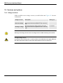
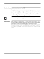
User environment
FUMES AND GASES - Can be hazardous to your health.
It is the responsibility of the buyer/user to ensure that national statutes regarding the
working environment are respected. The following should also be implemented:
:
Action
• Make sure that satisfactory exhaust devices are installed and used.
• Make sure that there is sufficient lighting over the workplace.
• If possible use environment-friendly shielding gas and vegetable oil for splatter
cleaning.
3HEA 801215-001 Rev.- 2005-05
3
Safety
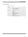
Reference document
Document
Described in:
Related safety instructions.
AW System manual, chapter introduction and safety
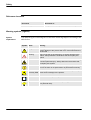
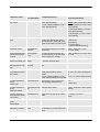
Warning symbols (signals)
Symbol
explanations
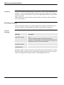
The different types of warnings are set out in the following chapters according to the
table below:
Symbol Name
Meaning
Danger
Warning that serious or life-threatening personal injury and/or
serious damage to the product will occur if the instructions are
not followed.
Warning
Warns of the risk of personal injury or serious damage to the
product. Always follow the instructions that accompany this
symbol.
Electric shock
Warns of possible electric shock that can cause life-threatening
or serious personal injury. Always follow the instructions that
accompany this symbol.
Caution
Draws your attention to the fact that damage to the product may
occur if an action is not performed or is performed incorrectly.
!
Static
The ESD symbol indicates a risk of static electricity that may
electricity ESD cause serious damage to the product.
4
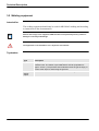
Note
Information about important parts.
Tips
This symbol refers to an instruction providing further information
on a particular step.
3HEA 801215-001 Rev.- 2005-05
Safety
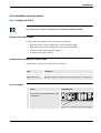
DANGER – Ensure that the main power switch is turned off.
2.2.1 DANGER – Ensure that the main power switch is turned off.
Description
Work with high voltage entails a potential lethal hazard. Persons subjected to high
voltages can suffer heart failure, burns or other serious injuries. To avoid such
injuries, never begin a job without first eliminating the risks to safety. These are
described below.
Elimination
Action
1.
Turn off the main power switch at the
control module.
2.
Turn off the main power switch at the
drive module.
Info/Illustration
1
2
3.
Single robot stations
3HEA 801215-001 Rev.- 2005-05
All voltage is lost when the main switch on
the drive module (DM1) is switched off.
5
Safety
WARNING – The unit is sensitive to ESD.
2.2.2 WARNING – The unit is sensitive to ESD.
Description
ESD (electrostatic discharge) is the transfer of electrostatic charges between two
objects with varying charges, either through direct contact or through an electrical
field.
The discharge contains very little electricity and is therefore not hazardous to
humans, however, electronics can be damaged by the high voltages.
Elimination
Action
Info/Illustration
1.
Use an ESD bracelet.
The bracelet must be regularly tested to
ensure that it is undamaged and functions
properly.
2.
Use an ESD-protected floor mat.
The mat must be grounded through a voltage
regulating resistor.
3.
Use an ESD-protected table mat.
The mat shall produce a controlled discharge
of static electricity and must be grounded.
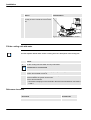
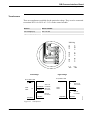
Location of attachment point for ESD bracelet
Button (A/B) for the ESD bracelet is located on the computer unit in the control
module. The location is shown in the following figure.
B
A
xx0400001061
Drivmodul, bild på knapp
för ESD
Figure 1 Location of attachment point for ESD bracelet
Item Name
6
A
Attachment point for ESD bracelet in the control module.
B
Attachment point for ESD bracelet in the drive module.
3HEA 801215-001 Rev.- 2005-05
Technical Description
Principle design
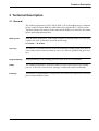
3 Technical Description
3.1 General
The welding equipment A314E/316E/A324E-L (E for Extended range) is adapted
for the control from the IRB 140/1400/2400 robot with the IRC5 control system.
Together with the AW software in the robot and the PIB process interface the system
has the following characteristics:
Working area
With an optical tachometer, with a high frequency resolution in the wire feed unit,
a stable wire feed is obtained, across the speed range:
0.3 m/min. – 30 m/min.
Accuracy
The transfer of information between the robot and the welding equipment is done in
series in the form of numerical data by way of a CAN bus, guaranteeing great accuracy.
Programmability
All programming of the welding process is done from the FlexPendant.
Safety
The welding equipment is fitted with sensors for the supervision of the welding
process. If an error occurs an error message is displayed on the FlexPendant.
Flexibility
The transfer of programmable configuration data enables the adaptation to different
power sources and feed units.
3HEA 801219-002 2005-05
7
Technical Description
Welding equipment
3.2 Welding equipment
Intended for
The welding equipment should only be used for MIG/MAG welding and according
to instructions in the documentation.
With all other usage of the equipment. ABB disclaims all responsibility and any claims for
damages or warranty undertakings
The equipment is not intended for use in explosive environments.
Tryckvakter
8
Type
Description
Gas sensor
The pressure switch functions as an open contact, which closes when the
pressure rises. The switch is pre-calibrated for 0.2 bar (equivalent of
approx. 5 l/min.). The pressure switch indicates when the gas is empty, or
if some other object is obstructing the gas flow.
Water
sensor,
Option
A water sensor is selected when a water cooled welding torch is included.
3HEA 801219-002 2005-05
Technical Description
Principle design
3.3 Principle design
The welding equipment consists of:
Components
Wire feed system
Type
• A314E (for robot IRB 1400)
• A316E (for robot IRB 1600)
• A324E-L (for robot IRB 2400)
Welding power
source
• RPB 320/420/520
• LRC 430
• MigRob 500
Options
The following options are available for the Welding
equipment:
• welding torch set (Dinse, Binzel)
• joint locator, "Smartac"
• torch cleaner “TC”
• wire cutter
• automatic TCP-gauging “BullsEye”
3HEA 801219-002 2005-05
9
Technical Description
Robot Welding System
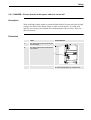
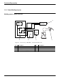
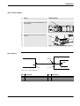
3.3.1 Robot Welding System
Welding power source LRC 430
5
A314E/A316E/
A324E-PIB
IRC5
PIB
Option
Option
Smartac
TC
Bullseye
LRC
CANbus
1
2
3
4
Figure 2. Overview of “ARCITEC” connections LRC 430
10
Pos
Description
Pos
Description
1
Control module
4
Collision sensor
2
Welding power source
5
Gas/water sensor
3
Wire cutter/ BullsEye (option)
3HEA 801219-002 2005-05
Technical Description
Principle design
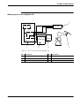
Welding power source MigRob 500
5
A314E/A316E
A324E-PIB
IRC5
PIB
Option
Option
Smartac
CANbus
TC
Bullseye
M igRob 500
1
2
3
4
Figure 3. Overview of connection MigRob 500
Pos
Description
Pos
Description
1
Control module
4
Collision sensor
2
Welding power source
5
Gas/water sensor
3
Wire cutter/ BullsEye (option)
3HEA 801219-002 2005-05
11
Technical Description
Robot Welding System
Welding power source RPB
A314E/A316E
A324E-PIB
5
IRC5
Option
RPB
CANbus
Device Net
TC
BullsEye
PIB
Option
Smartac
1
2
3
4
Figure 4. Overview of connections RPB
12
Pos
Description
Pos
Description
1
Control module
4
Collision sensor
2
Welding power source
5
Gas/water sensor
3
Wire cutter/ BullsEye (option)
3HEA 801219-002 2005-05
Technical Description
Principle design
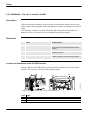
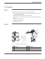
3.4 Components
General
The welding equipment can include the following components:
• Wire feed unit mounted on the robot arm and fitted with a Euro-socket for
connecting the welding torch.
• Attachment for the wire feed mechanism and cables.
• Hoses for gas, water and compressed air, as well as cables for signal and power
supplies.
• Cable for the welding current.
• Cable for the power source
• Welding power source
Overview
4
5
3
2
1
Figure 5. IRB 2400 with welding equipment
Pos
Description
Pos
Description
1
Welding power source
4
Wire feed unit
2
Attachment
5
Wire conduit
3
Hoses/cables for welding current
3HEA 801219-002 2005-05
13
Technical Description
Wire feed systemA314E/316E/A324E-L
3.5 Wire feed systemA314E/316E/A324E-L
3.5.1 General
There are two options of wire feed systems:
• Bobbin
• Marathon pac.
A314E/316E/A324E-L should be used for gas arc welding.
It is intended to be mounted directly on the robot IRB 1400/IRB1600/IRB 2400L,
which results in a short cable bundle and a good wire feed, furthermore, a smaller
floor area is required.
Bobbin
If a bobbin is used it may be necessary to adjust the brake hub. See “Adjusting the
brake hub (bobbin)” on page 33
Working area
The wire feed system A314E/316E/A324E-L meets Arc Welding & Application
Equipment’s recommended layout setup.
This means the robot has a full working area within a section of ±150° for A314E/
316E/A324E-L, around axle 1.
Great care should be exercised outside of this sector, e.g. when programming otherwise the
welding equipment can be damaged.
This is especially the case for IRB 1600 and “Bending backwards” movements.
Technical specifications and requirements
14
Type
Data
Wire diameter
0,8 mm - 1,6 mm
Max wire feed speed
30 m/min.
Permitted ambient temperature
0ºC - +40ºC
3HEA 801219-002 2005-05
Technical Description
Principle design
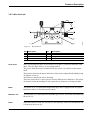
3.5.2 Wire feed unit
2
4
1
5
1
3
3
j5000841
6
Figure 6. Wire feed unit
Pos Description
Pos
Description
1
Upper feed roller
4
Motor
2
Adjuster screw
5
Inlet guide
3
Lower feed roller
6
Screw
Feed rollers
Wire is fed using two pairs of feed rollers, see Figure 8, which are linked to each
other. The two upper rollers (1) are spring-loaded.
The power from the motor is transferred to the rollers via a pinion on the motor
shaft.
The pressure between the upper and lower rollers can be adjusted individually using
an adjuster screw (2).
All rollers are fitted with sleeve bearings.
The lower feed rollers (3) have grooves for two different wire diameters. The rollers
are turned so that the marking for the required wire diameter is facing forwards.
Motor
The motor (4) is of a permanent magnetized type and is equipped with an optical
tachometer meter for accurate speed control.
Marathon Pac
An inlet guide (5) is fitted when the marathon pac is used. The nozzle is locked using
the screw (6).
Bobin
When the bobbin is used, the wire liner is fitted directly to the feed mechanism and
is locked by the screw (6).
3HEA 801219-002 2005-05
15
Technical Description
Control and indicating devices on the wire feed unit
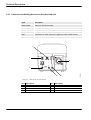
3.5.3 Control and indicating devices on the wire feed unit
Type
Description
WIRE FEED
Switch for manual wire feed.
RESET (Option)
Switch for resetting the torch collision sensor.
AIR
AIR connection to the welding torch.
IN
Connection for water (blue hose). Applies to water cooled torches.
OUT
Connection for water (red hose). Applies to water cooled torches.
Euro-socket
Connection for the welding torch.
1
2
6
4
j5000842
5
3
Figure 7. Side of the wire feed unit.
16
Pos Description
Pos Description
1
Switch “WIRE FEED”
4
Connection “IN”
2
Switch “RESET” Option
5
Connection “OUT”
3
Connection “AIR”
6
Euro-socket
3HEA 801219-002 2005-05
Installation
Connection of welding equipment
4 Installation
4.1 Connection of welding equipment
All personnel working with the welding robot system must be fully conversant with the applicable safety instructions that are available.
The cables and hoses are connected as follows. For more information, see Figure 12.
Cable/Hose
Type
Connection
Feeder cable 1
(signal cable)
A314E/316E/
324E-L
Foot of the robot - Control module
23-pole connection at both ends.
Figure 8. Connection on control module
Feeder cable 2
(Power cable)
A314E/316E/
324E-L
Foot of the robot - Control module
12-pole connection at foot of the robot and 19-pole
connection at Control module.
.
Figure 9. Connection on control module
Gas
Red hose
Connected to the central gas supply or to the gas
cylinder.
Cooling water
Blue hose (1)
Red hose (2)
IN
OUT
1
2
Figure 10. Wire feed unit
3HEA 801219-002 2005-05
17
Installation
Overview
Cable/Hose
Type
Connection
Air in
PVC-slang D14/8 Connected to the compressed air supply, system
pressure, approx., 6 bar.
Wire guide input (1) for bobin
for Marathon Pac
Welding cable (2)
1
95 m2
2
Figure 11. Wire feed unit
Current cable
Connect the current cable from the wire feed unit to
the power source.
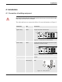
4.1.1 Overview
1
8
2
6
5
4
j5000843
7
3
Figure 12. Connections on wire feed unit
18
Pos
Description
Pos
Description
1
Feeder cable 1
5
Water IN (blue hose)
2
Feeder cable 2
6
Air hose
3
Hose for gas (red)
7
Welding cable
4
Water OUT (red hose)
8
Wire guide
3HEA 801219-002 2005-05
Installation
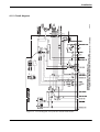
Circuit diagram
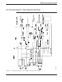
4.1.2 Circuit diagram
504806c01
Figure 13. Circuit diagram, wire feed unit A314E/316E/324E-L
3HEA 801219-002 2005-05
19
Installation
Connection of feeder cables
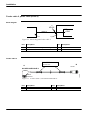
4.1.3 Connection of feeder cables
Feeder cable 1, signal cable (FEED 1)
Block diagram
2
XP106
PIB
TB6
FEED 1
1
3
Figure 14. Block diagram Feeder cable 1
Pos
Description
Pos
1
Wire feed unit, circuit diagram see Figure 13. 3
2
Connection
Description
Control module
Feeder cable 1
EXT. FEED 1
A
XP106
xxx xxx xxxx
B
503281A1
A314/E316/A324E-L
IRB-CS
Robot foot
Figure 15. Feeder cable 1, A314E/A316E/A324E-L.
20
Pos
Description
Pos
Description
A
Wire feed unit
B
Control module
3HEA 801219-002 2005-05
Installation
Connection of feeder cables
Signal
description
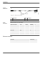
Signal description for feeder cable 1 A314E/A316E/A324E-L:
Signal description
A
B
Color
Gun Reset
Gun Crash Sensor
Current Sensor
Water Flow Sensor
Gas Flow Sensor
Tacho +
Tacho - (Encoder Tacho input)
Manual Wire Feed
24 VDC Supply
0 VDC (24 VDC) / Encoder Tacho Common
Motor Temperature
Auxiliary Motor
ADM Tacho (+) Encoder Tacho input
ADM Tacho (-)
+5V Encoder Tacho
Spare (not used)
B
B
N
N
P
P
D
D
F
F
K
K
L
L
A
A
J
J
C
C
M
M
E
E
G
G
H
H
R
R
S
S
White
Brown
Green
Yellow
Gray
Pink
Blue
Red
Black
Violet
Gray/Pink
Red/Blue
White/Green
Brown/Green
White/Yellow
Yellow/Brown
3HEA 801219-002 2005-05
21
Installation
Connection of feeder cables
Feeder cable 2, power cable (FEED 2)
Block diagram
2
1
2
XP105
PIB
TB5
FEED 2
3
1
Figure 16. Block diagram Feeder cable 2
Pos
Description
Pos
1
Wire feed unit, circuit diagram see Figure 13. 3
2
Connection
Description
Control module
Feeder cable 2
EXT. FEED 2
xxx xxx xxxx
A
B
XP105
503284A
A314E/A316E/A324E-L
IRB-CP
Robotfoot
Figure 17. Feeder cable 2, A314E/A316E/A324E-L.
22
Pos
Description
Pos
Description
A
Wire feed unit
B
Control module
3HEA 801219-002 2005-05
Installation
Connection of feeder cables
Signal
description
Signal description for feeder cable 2 A314E/A316E/A324E-L
Signal description
A
B
Color
Motor +
A
A
White
Motor +
B
B
Brown
Motor +
C
C
Green
Motor -
D
D
Yellow
Motor -
E
E
Gray
Motor -
H
H
Pink
Pneumatic Spatter Cleaning (42/115VAC)
G
G
Blue
Gas Valve (42/115 VAC)
K
K
Red
Arc Voltage Gun
M
M
Black
Smartac 1
L
L
Violet
Aux Motor Supply (42/115 VAC phase)
J
J
Gray/Pink
Aux Motor Supply (42/115 VAC common)
F
F
Red/Blue
3HEA 801219-002 2005-05
23
Installation
Configuration of Welding Equipment
4.2 Configuration of Welding Equipment
4.2.1 General
On delivery the equipment is configured according to the applicable configuration
data which is stored on the disk that comes with the delivery.
The data can be read and modified by way of the robot FlexPendant.
4.2.2 Installation disk
As the disk is unique for the equipment supplied it should be stored in a safe place. The
program number indicated on the disk corresponds to the configuration in question, and
should be referred to in case of service matters regarding the function of the welding equipment.
The following files on the installation disk contain configuration data for the welding equipment:
File
RPB_FhpE.cfg
Lrc_FhpE.cfg
MigRob_FhpE.cfg
Configuration data for:
• welding power source RPB 320/420/520and
• wire feed unit A314E/316E/324E-L_PIB
• welding power source LRC 430 and
• wire feed unit A314E/316E/324E-L_PIB
• welding power source MigRob 500 and
• wire feed unit A314E/316E/324E-L_PIB
4.2.3 Reload configuration data
In case this configuration data must be reloaded, proceed in one of the following
ways:
24
Alternative
Description
Reboot the robot
The original configuration will be restored.
Loading using the
FlexPendant
In those cases where individual parameters need to be
changed compared to the original configuration.
Loading a new configuration
file
(EIO:CFG) Executed by way of the robot instruction:
System Parameters\File\Add or Replace
Parameters\ "file".cfg.
For more information, see “Configuration” on page 52.
3HEA 801219-002 2005-05
Installation
Connection of Welding Power Sources
4.3 Connection of Welding Power Sources
4.3.1 Welding power source LRC 430
Block diagram
Power source LRC/MigRob is connected to terminal A12.X2 on the control module.
1
2
A12.X2
PIB
TB3
3
Figure 18. Block diagram LRC/ MigRob
Pos
Description
Pos
Description
1
Welding power source
3
Control module
2
Terminal
Control cable
B
6
A
A
Cable LRC Signal Ext.
3HEA800788 - 001
XXX - XXX
1
Cable LRC Signal Ext.
3HEA800788 - 001
XXX - XX X
LRC
MigRob 500
B
A12.X2
CABLE LRC signal EXT.
503354A1
3HEA 800788-00x
XXX-XXX
Figur 19 Control cable for LRC /MigRob
Pos
Description
Pos
Description
A
Welding power source
B
Control module
3HEA 801219-002 2005-05
25
Installation
Welding power source LRC 430
Signaldescription
Signal description for control cable LRC/MigRob:
Signal description
Part/Core
A
B
Spare
1
D
1
Spare
2
E
2
Ext. enable
3
F
3
Ext. enable
4
C
4
Welding minus (OKC)
5
M
5
Welding measure - (Ext.)
6
J
6
Welding measure + (Ext.)
7
H
7
Shield
SH
SH
PE
Connecting CAN-bus/ DeviceNet
Action
1. Connect the CAN-bus from welding
power source to output X107 on the control module.
This output is internally connected to the
control system’s CAN-bus loop, output
A35.X1
Info/Illustration
1
Figure 20. Cable inlets on control module
26
3HEA 801219-002 2005-05
Installation
Welding power source RPB
4.3.2 Welding power source RPB
Block diagram
Power source RPB is connected to terminal XS107 on the control module.
..
2
XS107
PIB
TB3
1
3
Pos
Description
Pos
Description
1
Welding power source
2
Control module
2
Terminal
Control cable
B
A
XP107
RPB
EXT. CABLE PS RPB
505826-8XX
xxx xxx xxxx
503218C1
XS weld
Smartac
Figure 21. Control cable RPB
Pos
Description
Pos
Description
A
Control module
B
Welding power source
3HEA 801219-002 2005-05
27
Installation
Reference documents
Signaldescription
Signal description for control cable RPB:
Signal description
Part/Core
A
B
0V
wh (par 1)
B
B
Start PS
bu (par 1)
C
E
Ref.
wh (par 2)
A bridged with D
-
0V
or (par 2)
D bridged with A
A
WELD-/WELDOBJ.
F
-
Shield
SH
NC
XS WELD
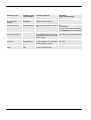
4.3.3 Reference documents
Document
Document ID.
Product manual for welding power source LRC
Product manual for welding power source MigRob 500
Product manual for welding power source RPB
Welding torch PKI
Welding torch Binzel
28
3HEA 801219-002 2005-05
Installation
Installation of accessories
4.4 Installation of accessories
4.4.1 Cooling unit OCE 2
C
The cooling unit is included in welding torch set PKI 500R and Binzel WH 455D
Connect the cable bundle
Connect the cable bundle to the cooling unit as follows:
• Red water hose to the cooling unit’s return connection IN.
• Blue water hose to the cooling unit’s feed connection OUT.
• Air hose to the compressed air supply.
• Gas hose to the gas cylinder.
Connect the cooling unit’s mains cable
Connect the cooling unit’s mains cable as follows:
Type
Connection
RPB
Mains cable for cooling unit is connected to welding power source.
MigRob/LRC 430
The mains cable is connected to terminal A12.K11 in control module.
LRC 430/ MigRob
Action
Info/Illustration
1. Cable entry can easily be made through
the cover on the control module for process options.
1
Figure 22. Cable inlets on control module
3HEA 801219-002 2005-05
29
Installation
Cooling unit OCE 2
Action
2. Connect the cable from the cooling unit
to relay A12.K11 inside the control module.
Info/Illustration
2
Figure 23. Terminals in control module
Fill the cooling unit with water
See the separate manual under section “Cooling unit” for a description of the cooling unit.
Action
1.
Fill the cooling unit with water and any anti-freeze.
Distilled water is recommended
2.
Check the flow in the welding torch by opening the cooling unit’s return hose connection IN until water comes in.
3.
If the water guard is ordered afterwards, the strap in the wire feed unit must be
removed before the guard can be used.
This is done as follows:
• Unscrew the strap By1 on the terminal in the wire feed unit between connections
2 and 4.
Reference document
Document
Document ID.
Product manual for OCE2
30
3HEA 801219-002 2005-05
Installation
Torch cleaner
4.4.2 Torch cleaner
Action
Info/Illustration
1. Cable entry can easily be made through
the cover on the control module for process options.
1
Figure 24. Cable inlets on control module
2. Connect the Torch cleaner to terminal
A12.X1
2
Figure 25. Terminals in control module
Block diagram
.
2
A12.X1
PIB
TB4
1
3
Figure 26. Block diagram
Pos
Description
Pos
Description
1
Torch cleaner
3
Control module
2
Terminal
3HEA 801219-002 2005-05
31
Installation
Torch cleaner
A
B
A12.X1
EXT. CABLE TCH-CLEAN
xxx xxx xxxx
503293A01
Cable for
Torch cleaner
Figure 27. Cable for torch cleaner
Signal
description
Pos
Description
Pos
Description
A
Torch cleaner
B
Control module
Signal description for Torch cleaner.
Signal description
Color
A (TC96)
A(BINZEL)
B
24V DC
White
4
6
1
0V DC
Brown
2&8
3, 4 & 5
2
Lubrication
Green
11
8
3
Cleaning
Yellow
10
7
4
Wire cutter
Gray
1
NC
5
Cleaning Finished
Pink
7
9
6
BullsEye
Blue
16
10
7
Shield
SC
NC
NC
PE
Reference documents
Document
Document ID.
Product manual for TC96
Product manual for Binzel
32
3HEA 801219-002 2005-05
Installation
Adjusting the brake hub (bobbin)
4.5 Adjusting the brake hub (bobbin)
If a bobbin is used it may be necessary to adjust the brake hub.
At high wire speed and when the bobbin is new, the wire can roll off when the wire feed unit
stops. To correct this, change the brake hub’s preset value of 5 kpcm (= 0.5 Nm).
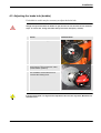
Action
Info/Illustration
1. Localize the brake hub (1).
1
2. Turn the knob (2) on the brake hub until
the arrows are in line with each other
(locked bobbin position).
3. The springs (3) on each side of the knob
are screwed in at the same time to
increase the braking force.
3
2
3
If the wire feed speed is so high that this adjustment does not have any effect, Marathon Pac
should be used.
3HEA 801219-002 2005-05
33
Installation
Before commissioning
4.6 Before commissioning
!
All guards and all safety equipment must be positioned before the station is commissioned.
This should be especially observed in connection with maintenance and service.
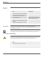
Before commissioning, the following should be checked:
Action
34
1
Check that no tools have been forgotten.
2
Check that the fixture and workplace are well secured.
3
Check that all parts and guards are in place and that they are well secured.
4
Check that all functions are correct.
3HEA 801219-002 2005-05
Maintenance
Wire feed unit
5 Maintenance
This work must only be carried out by persons trained in the complete installation, and who
are aware of the special risks involved with its different parts.
!
Disconnect the mains supply and (if possible) secure the switch before starting work on the
equipment.
In some cases however, it is necessary to work with the mains supply switched on, special
care and safe working methods must be used.
Note!
Only use genuine spare parts and extra accessories recommended by ABB.
5.1 Wire feed unit
2
4
1
5
1
3
j5000841
6
Figure 28. Wire feed unit
Pos Description
Pos
Description
1
Upper feed roller
4
Motor
2
Adjuster screw
5
Inlet guide
3
Lower feed roller
6
Screw
3HEA 801219-002 2005-05
35
Maintenance
Before commissioning
Regularly
Action
Info/Illustration
1. Make a visual inspection of the equipment.
• Correct errors, if any, for reliable operation.
2. Purge the inside of the feed unit as necessary
by compressed air at reduced pressure.
3. Clean the grooves in the feed rollers and the
bore of the outlet nozzle.
To ensure satisfactory wire feeding
the grooves in the feed rollers should
be cleaned at regular intervals.
4. The wire conduit should always be purged by
compressed air when changing the wire and as
necessary.
• When worn out, change the wire conduit.
5. Use filler wire free of impurities.
Wire changing
Dirt can cause slipping.
There are two grooves in the feed rollers, one for each wire diameter.
To change grooves the rollers are turned so that the markings for the required wire
diameter come outwards.
The bearings of the motor and the gear box are permanently lubricated - maintenance-free.
5.1.1 Before commissioning
:
!
All guards and all safety equipment must be positioned before the station is commissioned.
This should be especially observed in connection with maintenance and service.
Action
36
1
Check that no tools have been forgotten.
2
Check that the fixture and workpiece are well secured.
3
Check that all parts and guards are in place and that they are well secured.
4
Check that all functions are correct.
3HEA 801219-002 2005-05
Repair
Changing wire feed motor
6 Repair
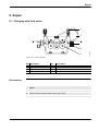
6.1 Changing wire feed motor
2
4
1
5
1
3
j5000841
6
Figure 29. Wire feed unit
Pos Description
Pos
Description
1
Upper feed roller
4
Motor
2
Adjuster screw
5
Inlet guide
3
Lower feed roller
6
Screw
Dismounting
Action
1. Release both feed rollers.
2. Remove the drive wheel and the three cap screws.
3. Lift out the motor.
3HEA 801219-002 2005-05
37
Repair
Before commissioning
Mounting
When replacing or repairing the drive motor the drive motor shaft must be centered to both
the feed rollers with a centering device to avoid wear on the cogs and bearings.
Action
1. Fit the new motor.
2. Center the motor’s drive shaft to both feed rollers by means of the centering device.
3. Fit the drive wheel and the three cap screws.
4. Fit the two drive rollers.
Centering device
Designation
Order number
Centering device
500 332-001
6.1.1 Before commissioning
!
All guards and all safety equipment must be positioned before the station is commissioned.
This should be especially observed in connection with maintenance and service.
Before commissioning, the following should be checked:
Action
38
1
Check that no tools have been forgotten.
2
Check that the fixture and workpiece are well secured.
3
Check that all parts and guards are in place and that they are well secured.
4
Check that all functions are correct.
3HEA 801219-002 2005-05
PIB Process Interface Board
General
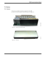
7 PIB Process Interface Board
7.1 General
The PIB is an I/O unit with integrated wire feed regulator communicating directly
with the ABB robot control system IRC5 for control and monitoring of the robot
welding.
The configuration is done in the same way as for a standard I/O unit.
The PIB characteristics are determined by the transfer of configuration parameters
for power sources and feed units.
The communication with the robot computer is serial and is maintained by way of a
CAN bus.
The PIB I/O connections are grouped together for direct cable connection to units
such as power sources, wire feed units, torch cleaners, sensors, etc., see Figure 30.
• welding power source
• wire feed unit
• torch cleaner
• sensors
3HEA 801219-002 2005-05
39
PIB Process Interface Board
Overview
7.1.1 Overview
7
6
5
4
3
2
1
0
8
9
10
PIB.wmf
1
11
Figure 30. Terminals on PIB
40
Pos
Description
Pos id
1
Terminal for power supply and interlocking
A121.TB1
2
Terminal for CAN-bus/DeviceNet
A121.TB2
3
Terminal for TSC
A121.TB4
4
Terminal for wire feed (signal)
A121.TB6
5
Terminal for wire feed (motor)
A121.TB5
6
Terminal for welding power source
A121.TB3
7
Terminal
A121.TB11
8
D-sub for loading program
9
Jumper
10
Switch for loading program
11
Euro connector “Add on board” for sensor
A121.TB9
3HEA 801219-002 2005-05
PIB Process Interface Board
Technical Specification
7.2 Technical Specification
7.2.1 Mechanical Data
Type
Data
Dimensions:
257x196x72.5 mm
Weight:
2.1 kg
Enclosure class:
IP 20
7.2.2 Electrical Data
Type
Description
Data
Power supply:
Figure 31. on page 49 -Transformers
Digital outputs:
Continuous load/output:
max 350 mA
Total output load:
max 1.6 A, < 70°C
Tripping of overload protection per output
370 mA
Remark: Regarding capacitive load > 0.05 uF a
temporary overload can arise at the start causing the overload protection to trip. If this occurs
a current-limiting resistor must be connected in
series with the connected load.
Digital inputs 24 V Incoming voltage, switch on:
DC:
Incoming voltage, switch off:
15 - 35 V
-35 to +5 V
Impedance
4 kohm, resistive
42V AC outputs:
Max current:
1A at < 70°C
Relay outputs:
Max voltage:
250V AC
Max current:
10 A
Note: Sparc protection has to be externally connected
Analog outputs:
3HEA 801219-002 2005-05
Outgoing voltage:
0 - 15 V, < = 100 mA,
< = 70°C.
41
PIB Process Interface Board
Environmental Data
7.2.3 Environmental Data
42
Temperature data:
Storage
Operation
According to:
Cold:
-40ºC, 16 h
+5ºC, 2 h.
IEC 68-2-1
Heat:
+70ºC, 16 h
+70ºC, 2 h
IEC 68-2-2
Change:
-40ºC / + 70ºC
2 cycles
IEC 68-2-14
Vibration:
EC 68-2-6
EMC: (Electro Magnetic Compatibility)
EN 50199
LVD: (Low Voltage Directive)
EN 60204
3HEA 801219-002 2005-05
PIB Process Interface Board
Safety
7.3 Safety
7.3.1 Personal Safety
Moving parts which according to the EU machinery directives might cause personal
injury are interlocked via the robot holding device and emergency circuit.
Such functions are:
• Manual wire feed
• Mechanical cleaning of the torch.
Interlocking
Figure 37. shows the build-up of the PIB interlocking system.
If national regulations require that also the power source shall be interlocked, the
interlocking system can be completed by a relay opening the control circuit of the
power source.
Manual wire feed
On manual wire feed via the welding torch or the push-button of the feed unit, the
wire can be fed without holding down the holding device up to max. 6 meters per
minute. The speed will increase as long as the push-button is activated.
Manual wire feed: See “Manual wire feed with PIB and IRC5” on page 60,
3HEA 801219-002 2005-05
43
PIB Process Interface Board
Machine safety
7.3.2 Machine safety
Collision Detection
The Collision detection robot function is set as standard on the A314E/316E/324EL systems.
Important!
The mechanical safety bracket function on PIB must be deactivated through the connection
of +24V to PIB input TB 6.2.
A lack of this signal will be interpreted as a collision by PIB and the wire feed will be
blocked.
Bridge By2, in the wire feed is prepared for this and on delivery is made when a safety
bracket is not installed. See note 2 Figure 13. on page 19.
Safety bracket
The mechanical safety bracket is ordered as an option.
Important!
Bridge By2, must be open when the safety bracket is installed. See note 2 Figure 13. on
page 19
The following description Collision Sensor 7.3.3 applies when the safety bracket is
installed.
44
3HEA 801219-002 2005-05
PIB Process Interface Board
Collision Sensor
7.3.3 Collision Sensor
General
The PIB is designed to be used with a welding torch with collision sensor.
In normal status the sensor is to supply 24V DC to the PIB input TB6.2.
The collision sensor controls the Run Chain relay in the PIB. The relay is of the twopole type and is integrated in the general stop chain (G-stop) of the robot. In normal
status the relay is active.
When the collision sensor is activated
When the collision sensor is activated the Run Chain relay opens, resulting in an
opened G-stop chain, leading to quick-stop of the motion due to the fact that the
robot goes from operation mode to stand-by mode. The error message G-stop comes
up on the robot programming unit. The message remains until it has been acknowledged by way of the OK button.
Operation after
collision
To enable putting the robot into operation again the G-stop chain must first be
closed.
If the torch has occasionally been out of position but has sprung back again, the Gstop chain closes and the robot is ready to be used again.
If the torch remains in the wrong position, for example after having collided with
the weld object, the fixture, etc., the robot must be moved in order to make the torch
spring back. On the front of the ABB wire feed units A-314 there is a spring-back
push-button (reset) for this purpose.
Reset
Operation after
collision
When the collision sensor is reset the PIB microprocessor activates the Run Chain
relay and closes the G-stop chain. It is then possible to put the robot into service
again, by using the robot joystick to manoeuvre the robot to make the torch spring
back, resetting the collision sensor in closed position. The reset function is automatically acknowledged.
Program start
The start of the running of the program is blocked until acknowledged. Trying to
start before acknowledgement will result in the Run Chain relay opening and the Gstop chain breaking. The reset procedure must then be repeated.
3HEA 801219-002 2005-05
45
PIB Process Interface Board
Collision Sensor
Limitations
To prevent the PIB remaining in the reset function - due to circuit interruption, for
example - and to ensure that a further collision will stop the robot, the reset time is
limited to 1 minute. After that the G-stop is interrupted again and the reset procedure
must be repeated.
What is said above applies both to manual running of the robot and to running by
way of the program.
Running by program
When running the robot by way of the program there appears an additional error
message, expressly indicating that the collision sensor has been activated.
The error
messages
Message
Description
Message 1:
PIB error, warning
Welding torch has crashed. If torch still crashed, reset from wire
feed.
• Move robot with joystick, its not allowed start prg.
Message 1 is shown together witth G-stop (general stop) if the
welding torch is still in an incorrect position.
Message 2:
PIB error, warning
Welding torch has been resetted.
Message 3:
PIB information
Torch back to normal position after being down.
Messages 2 and 3 will come up after restart in this order. If the collision is of short
duration and the torch breaks only momentarily and springs back again, message 1
will not be displayed. Messages 2 and 3 will be displayed, however.
46
3HEA 801219-002 2005-05
PIB Process Interface Board
Electronics
7.3.4 Electronics
Design
PIB is designed to withstand the short-circuiting of the outputs and overloading of
the motor regulator.
The overloaded output is switched off. The function resumes when the power supply
is switched on again after the power supply to the PIB has first been cut and the
overload eliminated.
Motor regulator
The motor regulator is protected by a current limiter on the drive stage.
Units
Units connected to the PIB are also protected as the max. and min. data can be
configured, for example, max. reference for the power source, max. speed of the
connected wire feed unit.
Error messages
As evident from “7.11 Diagnostics – Error Handling” on page 63 an error message
is displayed to demand a proposed action.The weld process is not interrupted.
3HEA 801219-002 2005-05
47
PIB Process Interface Board
Versions and options
7.4 Versions and options
7.4.1 Voltage versions
PIB is available in two voltage versions, see table bellow and Figure 32. for more
information.
Voltage version
Description
Ordering no.
Wire feed units with voltage supply to the final
stage of the feed unit regulator of max. 42V AC/
10A
501 700-880
005-Low voltage
Wire feed units with voltage supply to the final
stage of the feed unit regulator of max. 115V AC/
3.5A
501 700-881
006-High voltage
Warning! Connecting 115V AC to the low-voltage version of PIB will destroy the PC board.
The high-voltage version:
A protective earth conductor (min. 2.5 mm2) shall be connected between the upper PIB metal
bar and the protective earth bar of the robot cabinet before the unit is switched on.
48
3HEA 801219-002 2005-05
PIB Process Interface Board
Voltage versions
Transformers
There are transformers available for the particular voltage. They are to be connected
to terminal XT21 for 230V AC/ 3.15A in the control module.
.
Version
Article number
Low voltage (LV)
501 714-001
High voltage (HV)
501 714-002
brun/brown
gul/yellow
230V
50Hz
28V 3A
Uo=28.9V
vit/white
0-115V
0-28V
0-28V 0-28-42V
orange
vit/white
28V 3A
S2
Uo=28.9V
vit/white
gul/yellow
115V 2.7A
Uo=118.9V
gul/yellow
vit/white
501714c1
röd/red
42V 7.5A
Uo=43.5V
orange
S1
28V 7.5A
svart/black Uo=28.9V
P1
HV
-002
R=2,2 Ohm 10W
R=2,2 Ohm 10W
230V
50Hz
LV
-001
High Voltage
Low Voltage
gul/yellow
0-230V
0-230V
Marking
Figure 31. Transformer
3HEA 801219-002 2005-05
49
PIB Process Interface Board
Marking and Version Handling
7.5 Marking and Version Handling
Hardware version
Figure 32. shows the location and disposition of the article and manufacturing numbers. This marking indicates the hardware version of PIB – not the software one.
Extra marking
High voltage
Low voltage
Product for ABB
High voltage 006
Low voltage 005
Version number
ABB Welding
501 700-881
5601 006-1900
DAT: 2003-08-26
SNR: 1836280
Testing date
Serial number
Märkning.jpg
Article number
501 700-880, Low voltage
501 700-881, High voltage
Figure 32. Marking and Version Handling.
Software version
The software version is indicated under the configuration menu in the programming
unit for the robot as a non-editable four digit number. The number is automatically
updated when the software version is changed.
50
3HEA 801219-002 2005-05
PIB Process Interface Board
Options
7.6 Options
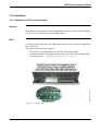
7.6.1 Smartac
smartac på PIB.jpg
The unit is an “Add on” unit and is connected to the PIB
by way of a 32-pole connector of the Euro type, see Figure 30.
smartac.jpg
Figure 33. Smartac connected to PIB
Figure 34. Smartac
3HEA 801219-002 2005-05
51
PIB Process Interface Board
Configuration
7.7 Configuration
7.7.1 General
Programmable parameters enable the adaptation to different types of welding equipment.
The configuration parameters determine:
• the control properties
• the scale factors
• the offset values
• the max. and min. values, etc.
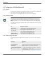
7.7.2 Configuration parameters
These factors are listed and their values can be edited on the FlexPendant under the
menu:
Misc\System\Parameters\IO signals\Types?Units\PIB-name
(=configured IO-name)
Modified values are automatically transferred to the PIB board when restarting the robot.
When changing the PIB
Previous configuration parameters stored in the robot will be automatically transferred to the new PIB card (Exception see chapter on page 53)
Configuration data for ABB’s standard welding equipment are included in the AW
system configuration diskettes
See “Configuration parameters” on page 65, where all the parameters are listed
and defined.
When changing PIB the unit must be restarted 2 times.
52
3HEA 801219-002 2005-05
PIB Process Interface Board
Installation
7.8 Installation
7.8.1 Adaptation to IRC5 control system
General
PIB includes two program versions, depending on the robot system. Which program
version is active is determined by the TB9 jumper.
IRC5
Bygling_TB9_överblick.jpg
For robot systems from IRC5 the TB9 jumper shall be open (removed or parked on
one of the pins).
The jumper in this position supports:
• The transfer of configuration data from the robot FlexPendant.
• Automatic transfer of configuration data from the robot when changing PIB.
See description in “Configuration parameters” on page 52.
.
Figure 35. Jumper TB9.
3HEA 801219-002 2005-05
53
PIB Process Interface Board
Connecting Cable Shields
At delivery
All PIB equipment delivered separately or as spare parts is pre-configured for ARCITEC/
LRA and wire feeder A314 (jumper TB9 closed) on delivery.
Type of delivery
Description
Complete system
When a complete system is delivered the TB9 position is
determined.
Spare part or component
For use together with IRC5 the jumper is removed and the
parameter transfer takes place according to “IRC5” on
page 53.
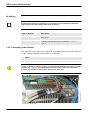
7.8.2 Connecting Cable Shields
The metal bar on the upper side of the PIB is provided with holes for the fitting of
2 cable clamps included with the delivery of the PIB.
Action
1. Screw the clamps tightly onto the metal bar.
Skärmning av kablar.jpg
In order for the PIB to function correctly it is important that the shield connections are made
precisely, see Figure 36. This mainly applies to the two cables from the wire feed unit. If
possible, they should be routed at some distance from each other.
Figure 36. Shielding.
54
3HEA 801219-002 2005-05
PIB Process Interface Board
Signal Connections
7.8.3 Signal Connections
For more information see Figure 30. on page 40, and Figure 37. on page 59.
TB stands for Terminal Block.
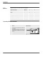
7.8.4 Table - Signal Connections
TB1, Power Supply and Interlocking
Designation
Function,
Voltage
1
Motor Supply
AC
Power supply for the motor regulator, interlocked
42V max. for PIB 501700-880 115V max. for
PIB 501700-881
2
Motor Supply Common
AC
Zero, power supply
3
Supply solenoid valves
AC
Power supply not interlocked for solenoid
valves and push feed unit
4
Logic supply
28V AC
Power supply for logic circuits
5
Logic supply common
0V AC
Zero, power supply for logic circuits
6
Ground
0V DC
Ground, screen
7
I/O 24 VS
DC
8
Manual Wirefeed out
24V DC
9
Run Chain A1
Relay contact
Run Chain A
10
Run Chaiu A2
Relay contact
Run Chain A
11
Run Chain B1
Relay contact
Run Chain B
12
Run Chain B2
Relay contact
Run Chain B
13
24V Ext
24V DC
3HEA 801219-002 2005-05
Out
In
x
x
x
Explanation
Interlocked 24V DC
Control signal for closing the interlocking contactor
24V DC ( Figure 37. on page 59)
55
PIB Process Interface Board
Table - Signal Connections
TB2, CAN bus Connection
Designation
Function, Voltage
Out
In
1
Sys 0V
DC
System 0 (=Robot I/O zero
2
CAN Low
Serial communic.
CAN Low 1
3
Ground
DC
Ground, screen
4
CAN High
Serial communic.
CAN High 1
5
Sys 24V
DC
6
0V
DC
0 V for addressing
7
NA 0
Jumper, NC=active
Binary addressing, not connected to TB2:6=1
8
NA 1
Jumper, NC=active
Binary addressing, not connected to TB2:6=2
9
NA 2
Jumper, NC=active
Binary addressing, not connected to TB2:6=4
10
NA 3
Jumper, NC=active
Binary addressing, not connected to TB2:6=8
11
NA 4
Jumper, NC=active
Binary addressing, not connected to TB2: 6=16
12
NA 5
Jumper, NC=active
Binary addressing, not connected to TB2: 6=32
x
Explanation
System 24 V (=Robot I/O 24 V)
1. Terminator resistor 120 Ohm to be fitted between TB2/2 and TB2/4 if PIB is the farthest off I/O unit in the system. See recommendations regarding the connection of terminator resistance in the robot product manual.
TB3 Connection to Power Source
Designation
Function, Voltage
Out
In
Explanation
1
Start Power Source A Closing contact
x
Control relay for power source
(or cooling fan, ARCITEC)
2
Start Power Source B Closing contact
x
Control relay for power source
(or. cooling fan, ARCITEC)
3
Weld ref.
Analog 0-15 V
x
Reference for welding voltage
4
Ref. Common
Analog common
x
Reference zero
5
Induct. Ref
Analog 0-15 V
x
Reference for setting of the inductance
6
Weld Object
Analog
7
Arc Voltage Gun
Analog
8
Arc Voltage object
Analog
9
24 V Ext
Supply voltage
x
For external relay
10
0V
Supply voltage
x
For external relay
11
NC
x
x
Sensing the welding voltage on weld object 1
Return the welding voltage to power source
Sensing the welding voltage on weld object for
PDM.2
Not connected
1. Common connection to the welding object and the power source, negative pole for Smartac/PIB.
2. PDM=Process Data Monitoring.
56
3HEA 801219-002 2005-05
PIB Process Interface Board
Table - Signal Connections
TB4 Connection to torch cleaner and TCP detector
Designation
Function, Voltage
Out
In
Explanation
1
24V DC
Supply
x
2
0V DC
Supply, zero
x
3
Lubrication
Digital 24V DC
x
Lubrication for cleaning reamer
4
Cleaning
Digital 24V DC
x
Cleaning reamer
5
Wire Cutter
Digital 24V DC
x
Cutting the wire
6
Cleaning finished
Digital 24V DC
x
Cleaning finished
7
Bulls Eye
Digital 24V DC
x
TCP search stop
In
Explanation
TB5 Connection 1 to Wire Feed Unit
Designation
Function, Voltage Out
1
Motor +
0-60/0-170V DC
2
x
Motor voltage
Motor -
x
Motor voltage
3
Pneum Spatter Clean- 42V AC
ing
x
To solenoid valve for Pneumatic spatter cleaning
4
Gas Valve
42V AC
x
To solenoid valve for shielding gas
5
Arc Voltage Gun
0-70V DC
6
Smartac 1
40V DC
x
Search voltage for Smartac Sensor 1
7
42V AC
Phase
x
Supply voltage for Push feed unit
8
42V AC Common
Zero
x
Supply voltage for Push feed unit
9
Smartac 2
40V DC
x
Search voltage for Smartac Sensor 2 1
10
Spatter Cleaning A
Closing contact
Alternative parallel function for TB5:3 2
11
Spatter Cleaning B
Closing contact
Alternative parallel function for TB5:3 2
12
Gas Valve A
Closing contact
Alternative parallel function for TB5:4 2
13
Gas Valve B
Closing contact
Alternative parallel function for TB5:4 2
14
Tig Mode
24V DC
x
Option
15
Feed Reverse
24V DC
x
Control signal for motor reversing
16
HF Ignition
24V DC
x
Option
x
Arc voltage feed-back 2
1. When using the Smartac sensor 2 TB5:5 and TB5:9 shall be bridged. See Product manual for Smartac.
2. Adapted contact protector required
3HEA 801219-002 2005-05
57
PIB Process Interface Board
Table - Signal Connections
TB6 Connection 2 to Wire Feed Unit
Designation
Function, Voltage
1
Gun reset
2
In
Explanation
24V DC
x
Resetting the collision sensor
Gun Crash
24V DC
x
Collision sensor
3
Current Sense
24V DC
x
Welding current sensor
4
Water Flow
24V DC
x
Water flow sensor
5
Gas Flow
24V DC
x
Gas flow sensor
6
NC
NC
7
Encoder TG INPUT
DC Puls
x
DC- or AC-tacho/input for encoder tacho
8
Man. Wire Feed
24/DC
x
Manual wire feed
9
+ 24V
Supply voltage
x
Supply voltage
10
0V
Supply voltage
x
Supply voltage/ common for encoder tacho
11
Temp
Analog
12
Aux Motor
24V DC
13
PDM Tacho +
AC/DC
x
Tacho for Process data monitoring
14
PDM Tacho -
AC/DC
x
Tacho for Process data monitoring
1
15
+ 5V (alt + 15V )
DC
Out
Bridged with TB 6/10
x
x
Temperature sensor in wire fed unit
Control signal for Push feed unit
x
Supply voltage for encoder tacho
1. PIB High Voltage
TB11
Designation
Function, Voltage
1
Weld Current A
2
In
Explanation
Analog
x
Shunt connection for PDM
Weld Current A
Analog
x
Shunt connection for PDM
3
HF Ignition
24V DC
x
Indication of HF ignition, Option
4
Smartac sense detect 24V DC
58
Out
x
Alternative for sens. detect. via CAN-bus
3HEA 801219-002 2005-05
PIB Process Interface Board
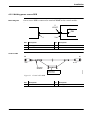
Elementary Diagram - Power Supply and Interlocking
502540s4c+
7.8.5 Elementary Diagram - Power Supply and Interlocking
Figure 37. Elementary Diagram - Power Supply, safety and Interlocking.
3HEA 801219-002 2005-05
59
PIB Process Interface Board
Manual wire feed with PIB and IRC5
7.9 Manual wire feed with PIB and IRC5
7.9.1 Possibilities and limitations
Manual wire feed can be carried out in three different ways:
• By pushing in the non-locking push button for manual wire feed on the welding
torch or on the front of the wire feed unit.
• By activating the function Manual wire feed from the robot's Flexpendant in
test mode under:
Program window\Arcweld\Manual wirefeed.
• By activating the robot output doFEED in combination with the setting of a
speed reference under the I/O window in:
aoFEED_REF..
Characteristics
and differences
The table below shows the characteristics and differences between the methods.
Observe comment 3 below regarding the limitation in functionality for method 3.
Method Speed1
Ramping function
Safety pad
Setting the reference
pressed in
1
Max. 6m/min.
yes
no
automatically
2
Max. 9m/min.
yes
yes
automatically
3
The full speed
range
no
yes
yes, manually
Limited validity2
1. Speed: If the speed range is limited by the configuration parameters MotorMaxSpeed or MotorMinSpeed the limitation applies.
For ARCITEC it also applies: If the speed range is limited by the configuration parameter MotorMachineID the limitation applies.
2. Note: The reference only applies as long as aoFEED is not changed by any other function: The methods 1 and 2 or execution of a program with another value. After using methods 1 or 2 the reference is reset.
60
3HEA 801219-002 2005-05
PIB Process Interface Board
Possibilities and limitations
Explanation
The table below shows the differences between the methods.:
Method Explanation
1
The arc weld function “Manual Wire feed” in the robot is called from PIB. The
robot input diMAN_WF is activated. The robot activates the output doFEED with
a reference in aoFEED that increases as a function of the time the wire feed
button is pressed in. The function is active as long as the button is pressed in.
The speed is limited to max. 6 m/min. by PIB1.
2
The arc weld function “Manual Wire feed” is called from the robot's programming unit. The robot input diMAN_WF is activated. The robot activates the output doFEED with a reference in aoFEED that increases as a function of the time
the Manual feed button is pressed in. The function is active as long as the button
is pressed in.
3
The reference range is expressed as
0 - 0.5 m/s (0 - 30 m/min.).
The function is active as long as doFEED is set to 1.
1. Limitation for reasons of personal safety.
3HEA 801219-002 2005-05
61
PIB Process Interface Board
Service and Programming Aids
7.10 Service and Programming Aids
7.10.1 CAN-Assist, art no. 502 800-880
Passive Mode
PC based tool that in Passive Mode allows listening to the CAN-bus traffic in the
Weld system during the current process.
Master Mode
In Master Mode, with the connection to the robot master disconnected, the I/Ofunction in the different units in the system can be activated, parameters loaded or
changed.
CAN-Assist is supplied as a package with hardware and a CD containing software
and documentation.
62
3HEA 801219-002 2005-05
PIB Process Interface Board
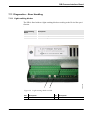
Diagnostics – Error Handling
7.11 Diagnostics – Error Handling
7.11.1 Light-emitting diodes
The PIB is fitted with two light-emitting diodes according to the DeviceNet specification.
.
Description
NS
(Network Status), indicates the function of the CAN bus.
MS
(Module Status), indicates the PIB function.
1
Lysdioder.jpg
Light-emitting
diode
2
Figure 38. Light-emitting diodes on PIB
Pos
Description
Pos
Description
1
MS
2
NS
3HEA 801219-002 2005-05
63
PIB Process Interface Board
In the event of an error on PIB
Error Handling
Indication
Description
Green light
Indicates correct function
Red light
Indicates incorrect function
Changing light
During the initiation phase, which can take a few seconds, the light of
the diodes changes.
7.11.2 In the event of an error on PIB
In the event of an error on PIB an error message is given to the FlexPendant as a
warning to call action, see “Error messages” on page 64.
The weld process is not interrupted but action is required.
Acknowledge error messages
Action
1. Error messages are acknowledged by pressing OK.
Error messages
From PIB with version numbers -503. -0702 and from -1100 and higher the number
of error messages is limited to the following:
Error messages
Description
80001 2 PIB error, warning Analog outputs outside limits
• Check the limits in ctrl.conf.part motor max/min. Speed
and max Volt.
80001 4 PIB error, warning Digital Output overloaded in PIB, fatal error
• Check the output connections.
• Reset with power switch.1
80001 11 PIB error, warning Supply voltage 24 Volt on PIB too low
• Check incoming power supply.
1. The overloaded (short-circuited) output is switched off by its overcurrent protection.
The weld process is only interrupted if the process supervision is affected. The function
resumes when the power supply to the PIB is switched on after the power supply to the PIB has
first been cut and the overload eliminated.
64
3HEA 801219-002 2005-05
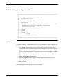
Configuration parameters
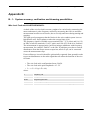
Appendix A:
A - 1: Configuration parameters
The configuration parameters are defined for 3 demands:
1. They should be an integer in order to simplify handling in the microprocessor
in the PIB.
2. The integer should be large enough so that the desired accuracy and resolution
are obtained.
3. Programming from the robot should be possible to be expressed in actual
quantities, for example, 21.4 m/min. for the wire speed, 32.2 V for the welding
voltage, etc. A multiplier with one or more indexes to the power of ten is
required in several cases:
The setting range for the parameters and a number that defines what the configuration value is to be multiplied by in order to express the true relation is
stated in the column “Parameter range/denomination” in “Table - Configuration parameters.” on page 68.
Example:
If “MotorCurrentLim” is defined to the value 80, the definition means
“Motor Current Limit {0...100}0.1 A” that the max permitted current is 8 A.
If “ProcEquipRefConv” is defined to the value 8260, the definition means
{1000...30000}E-3 that the relation Output voltage/Reference is 8.260 etc.
3HEA 801219-002 2005-05
65
Configuration parameters
The conversion factor for the wire feed with AC-tacho:
The conversion factor is obtained from
k0 =g x n x 100/(p x D x 60) [Hz/m/min. x 100],
where:
k0
is the conversion factor for tacho type 0
g
is the gearbox's gear factor
n
is the number of tacho periods/motor speed
D
is the feed roller's diameter in meters
100
is the multiple
In those cases k0 should be >65535, Tacho type 2 should be configured and at the
same time the conversion factor should be defined as k2 = k0 /2.
The maximum permitted tacho frequency is 27000 Hz, which limits the maximum
theoretical feed speed to Vmax = (p x D x 60 x 27000/(g x n)[m/min.]
Control parameters for the wire feed
The control parameters are:
• Feed Forward factor
• Motor Regulator P-factor
• Motor Regulator I-factor
These parameters are tested for the wire feed units supplied as standard and adjustment should be avoided. Modifications can result in incorrect speed or instability.
Adjustment ought to be carried out in consultation with service personnel from ABB
Automation Technologies AB
66
3HEA 801219-002 2005-05
Configuration parameters
Transfer of parameters between the robot and PIB
The configuration parameters are sent from the robot's system parameter memory to
the PIB each time the system voltage is switched on. If the parameters are equal to
those already in the PIB no writing to the PIB is carried out.
If the parameters in PIB differ to those being sent from the robot, for example, with
the replacement of PIB, the parameters that differ in PIB are written, which means
that the new PIB gets the same configuration as the previous one.
In order for the new parameters to apply the system must be restarted twice.
System definition
If the parameter “System definition”, is changed, which involves a change of the
I/O type for PIB, the parameter transfer takes place in two steps. First the redefinition of the new I/O unit in the robot takes place, which requires a restart.
During the next start the transfer to the PIB takes place and in order for the parameter to apply to the PIB another restart of the robot is required. Thus, in this case,
two restarts are required. The second time it is sufficient with a “warm boot” of the
system.
3HEA 801219-002 2005-05
67
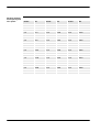
Table - Configuration parameters.
A - 2: Table - Configuration parameters.
The table contains all the parameters defined for PIB. They are shown and can be
edited from the robot's FlexPendant.
All parameters are not implemented as standard. Parameters that are implemented
and which must have the correct value to function correctly are marked by an asterisk and bold type.
Parameter name
Parameter name
Parameter behavior
in FlexPendant
Parameter
range/ denomination
Software Revision
SoftwareRevison
-
Motor Max Voltage
MotorMaxVoltage Maximum allowed voltage for the
DC-motor connected.
{0...110} V
60 (Used as standard value)
Motor Current Limit
MotorCurrentLim
Maximum allowed current for the
DC-motor connected.
{0...100} 0.1 A
100 (Used as standard value)
*Motor Max Speed
MotorMaxSpeed
Maximum allowed setting for
{0...500} 0.1
motor speed in motor speed quan- 300 (Used as standard value)
tity units
*Motor Min Speed
MotorMinSpeed
Minimum allowed setting for motor {0...500} 0.1
speed in motor speed quantity
5 (Used as standard value)
units
*Motor Regulator
P-factor
MotorRegPFactor Proportional factor of the motor
speed PI regulator.
{0...100}%
18 (Used as standard value)
*Motor Regulator
I-factor
MotorRegIFactor
Integrating factor of the motor
speed PI regulator.
{0...100}%
25 (Used as standard value)
*Motor Regulator
Feedforward-factor
MotorFeedForward
Feedforward factor of the motor
speed PI regulator.
{0...100}%
10 (Used as standard value)
Motor Temp Limit
MotorTempLimit
Maximum allowed temperature for {0...255} °C
the motor.
*Motor Brake Ratio
MotorBreakRatio
Defines the duty cycle of the brake {0...255}
transistor.
0 = No brake.
255 = Full brake
255 (Used as standard value)
Motor Control Error
Time Limit
MotorCtrlErrTimeLim
Defines the maximum allowed
{0...255} 1/10 s
time for difference between motor
speed set value and actual value
before setting the alarm
68
Current software revision (readonly)
3HEA 801219-002 2005-05
Table - Configuration parameters.
Parameter name
Parameter name
Parameter behavior
in FlexPendant
Parameter
range/ denomination
*Motor Tacho Conver- MotorTachoConv For AC: 100 Frequency in Hz for 1 {0...65535}
sion Factor
motor speed quantity.
20650 (Used as standard value)
For DC: 10000 Voltage in V for 1 AC (tacho type 0): 0.01 Hz / motor
motor speed quantity.
speed quantity
AC fast (tacho type 2): 0.02 Hz /
motor speed quantity
DC (tacho type 1): e-4 V / motor
speed quantity
*Motor Tacho
Type
MotorTachoType
Determines type of tacho connected and used by the motor
speed regulator of the PIB. Valid
types are AC-tacho and DC-tacho
{0,1}
0 (AC-tacho)
1 (DC-tacho)
2 (Fast AC-tacho
0 (Used as standard value))
Motor DC Offset
MotorTachoDCOffset
Motor speed offset for DC-tacho
connected
{-1000...1000} 0.01 m/min.
(Or r/min, l/min)
*Process Equipment
Reference Convers.,
Flexible
ProcEquipRef
Conv
Conversion factor between the
process quantity in the set value
and the reference voltage
{1000...30000}e-3 Process quantity / Vref
*Process Equipment ProcEquipRef
Reference Offset, Flx. Offset
Offset value for the process. Given {0...1000} 0.1 V
in process quantity units.
*Process Equipment
Max Reference Voltage
Maximum allowed reference volt- {0...1000} 0.1 V
age.
ProcEquipMaxRef
Process Data MoniPdmSpeedConv
toring Speed Conversion Factor
For AC: 100 Frequency in Hz for 1
motor speed quantity motor
speed.
For DC: 10000 Voltage in V for 1
motor speed quantity motor speed
{0...65535}
AC: 0.01 Hz / motor speed quantity
DC: e-4 V / motor speed quantity
Process Data Monitoring
Tacho Type
PdmTachoType
Type of tacho used for true process quantity measurement
{0,1}
0 (AC-tacho)
Process Data Monitoring
Tacho DC Offset
PdmTachoDCOff- PDM DC tacho offset
set
{-1000...1000} 0.01 motor speed
quantity
Process Data Monitoring Current Shunt
Conversion
PdmShuntConv
Scale factor for the shunt used in
PDM.
{0...65535} e-5 mV/A
15000
Process Data Monitoring
Shunt Offset
PdmShuntOffset
PDM Shunt offset
{-32000...32000} mA
*Sensor Detection
Sensitivity, Smartac
SensorDetection- Defines the search voltage drop
{0...255} 1/10 V
Sens
for detection of contact with workpiece
3HEA 801219-002 2005-05
69
Table - Configuration parameters.
Parameter name
Parameter name
Parameter behavior
in FlexPendant
Parameter
range/ denomination
*Sensor Search Voltage Valid Limit,
Smartac
SensorSearchVoltValidLim
Defines the lowest allowed search {0...40} V
voltage for start of search.
*System Definition
SystemDefinition
Defines the PIB system configura- (0,1)
tion
0 = (Flexible)
1 = Not in use (Arcitec S4CPlus)
2 = Integrated Power source IRC5
*Machine Identification code, ARCITEC
MotorMachineID
The motor machine identification {0..255}
for the wirefeed range of the cur- According to wirefeed motor cable
rent wirefeed motor. Only valid for
Arcitec system
Inductance Reference OptProconversion
cEquipRefConv
Conversion factor between the
process quantity in the set value
and the reference voltage
Inductance Reference OpProcEquipReOffset
fOffs
Offset value for the process. Given (0...1000) 0.1 V
in process quantity units.
70
(1000...30000)e-3 Process quantity / Vref
3HEA 801219-002 2005-05
Loading of configuration file
A - 3: Loading of configuration file
#**************************************************************
#
#
(c) ABB Automation Technologies AB,
#
Arc Welding Products
#
#
File: ESABMig_FhpE.cfg
#
Description:
#
ArcWeld PIB EIO-parameter configuration for PowerSource
#
ESABMig 400t/500t and WireFeeder A314E/A324E
#
with DC Pulsed Tacho.
#
Speed range 0.5 to 30 m/min.
#
Created:
#
Written by:
#
Version 1.0
#
1.0 LOJ
#
Initial Release
#
#**************************************************************
Installation
If you have received a config file on a CD, see example above, you can install it as
follows:
1. Copy the cfg-file to a floppy, or use a PC/ Laptop and the Ethernet/ Service
channel, use the FTP client to transport files manually between the PC and the
robot controller storage memory.
These actions are carried out in the same way as in a file manager or in Windows Explorer.
2. With the System Parameter Window of the FlexPendant displayed select:
FILE\ Add or replace parameters\
3. Select the cfg-file from the floppy, or from the directory that the file was
transferred to.
4. Make a restart.
More information can be found in the User´s Guide.
3HEA 801219-002 2005-05
71
Loading of configuration file
72
3HEA 801219-002 2005-05
System accuracy: verification and trimming possibilities.
Appendix B:
B - 1: System accuracy: verification and trimming possibilities.
Wire feed: Feed unit A314E/316E/A324E-L
A check of the wire feed unit's accuracy ought to be carried out by measuring the
motor tachometer's pulse frequency and not by measuring the fed wire and time
measurement in order to avoid errors, due to wire slip and errors during starting and
stopping.
The right speed presupposes that the friction in the wire conduit system is not so
high that the wire feed regulator reaches the current limit (10A).
The frequency signal is available across terminal TB6: 7 (5 V pulse) and 10 (0 V)
on PIB, or between terminals 13/4 (5V pulse) and 12/4 (0V) in the wire feed unit.
The measurement is appropriately carried out using a multimeter with frequency
measurement, for example, Fluke 87 or the like. If problems occur due to switchdisturbances from the motor current a capacitor, max 0.02 µF, can be connected
across the measurement clips.
If an oscilloscope is used it should be galvanically separated from ground in order
to prevent disturbances on the tacho signal that can affect the function of the wire
feed unit.
• The wire feed unit's configuration factor: 20650.
• The wire feed unit's pulse amplitude: 4.5 - 5V
• f = v ×G × N /(pi ×D × 60)
where:
f
Frequency, Hz
v
Wire speed, m/min.
G=24
The gear's gear ratio
N=60
Number of periods per turn of the motor
D=0,037 m
Feed roller's diameter (contact diameter for the welding wire)
3HEA 801219-002 2005-05
73
System accuracy: verification and trimming possibilities.
Relation between
the frequency and
wire speed
74
m/min.
Hz
m/min.
Hz
m/min.
Hz
0,5
103
10,5
2168
20,5
4233
1,0
206
11,0
2271
21,0
4336
1,5
310
11,5
2374
21,5
4439
2,0
413
12,0
2478
22,0
4542
2,5
516
12,5
2581
22,5
4646
3,0
619
13,0
2684
23,0
4749
3,5
723
13,5
2787
23,5
4852
4,0
826
14,0
2891
24,0
4955
4,5
929
14,5
2994
24,5
5059
5,0
1032
15,0
3097
25,0
5162
5,5
1136
15,5
3200
25,5
5265
6,0
1239
16,0
3304
26,0
5368
6,5
1342
16,5
3407
26,5
5471
7,0
1445
17,0
3510
27,0
5575
7,5
1549
17,5
3613
27,5
5678
8,0
1652
18,0
3716
28,0
5781
8,5
1755
18,5
3820
28,5
5884
9,0
1858
19,0
3923
29,0
5988
9,5
1961
19,5
4026
29,5
6091
10,0
2065
20,0
4129
30,0
6194
3HEA 801219-002 2005-05
System accuracy: verification and trimming possibilities.
Welding power sources
General
When using PIB to control the power source with an analog reference (Flexible
Mode) the reference characteristics are determined by the parameters:
• ProcEquipRefConv (gain),
• ProcEquipRefOffset (offset) and
• ProcEquipMaxRef (Max):
When replacing PIB or the power source the weld result can deviate from previous
result depending on the tolerances in the analog circuits in PIB and the power
source.
By adjusting one or both of the two first-mentioned parameters above it is possible
to eliminate the difference and avoid comprehensive modification to the weld program.
If a power source has no base voltage (reference is linear from 0 V) for example,
LRC and others, the gain is adjusted by ProcEquipRefConv.
On a power source that has base voltage (output voltage at ref. 0V) for example,
RPA and others, adjustment of both parameters is necessary. With several iterations
where Offset is adjusted at the lowest current weld value and the gain is adjusted at
the highest current weld value, the weld result is trimmed to acceptable similarity to
the result before the replacement.
Adjustment
The adjustment is appropriately made in small increments.
For example, if the welding voltage is assessed to be 5% too low, the configuration
value is reduced by a value that is < 5%, if the welding voltage is too high, the
configuration value is increased by < 5%, etc. Note - inverted conditions.
The procedure is repeated until the desired result is achieved.
The procedure is suitable if similarity between several power sources is required.
It is recommended that changes are noted for the PIB or the power source that have caused
the change if the standard configuration is not used.
3HEA 801219-002 2005-05
75
System accuracy: verification and trimming possibilities.
76
3HEA 801219-002 2005-05
3HEA 801219-002 2005-05