1
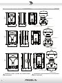
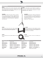
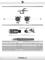
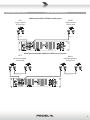
WAVE series
WAVE10P - WAVE12P - WAVE15P
passive loudspeakers
USER MANUAL
MANUALE D'USO
INDEX
INDICE
TECHNICAL SPECIFICATIONS . . . . . . . . . . . . . . . . . 3
FREQUENCY RESPONSE . . . . . . . . . . . . . . . . . . . . . 3
DIMENSIONS AND FLYING POINTS . . . . . . . . . . . . . 4
ACCESSORIES . . . . . . . . . . . . . . . . . . . . . . . . . . . . . 5
SPARE PART LIST . . . . . . . . . . . . . . . . . . . . . . . . . . . 5
INPUT PANEL (FIG.1) . . . . . . . . . . . . . . . . . . . . . . . . 6
CONNECTIONS (FIG.2) . . . . . . . . . . . . . . . . . . . . . . 6
CONFIGURATIONS (FIG.3) . . . . . . . . . . . . . . . . . . . 7
SAFETY AND PRECAUTIONS . . . . . . . . . . . . . . . . . . 8
IN CASE OF FAULT . . . . . . . . . . . . . . . . . . . . . . . . . . 8
TROUBLESHOOTING . . . . . . . . . . . . . . . . . . . . . . . . 8
CE CONFORMITY . . . . . . . . . . . . . . . . . . . . . . . . . . . 8
PACKAGING, SHIPPING AND COMPLAINT . . . . . . . 8
WARRANTY AND PRODUCTS RETURN . . . . . . . . . . 9
INSTALLATION AND DISCLAIMER . . . . . . . . . . . . . . 9
GENERAL INFORMATION . . . . . . . . . . . . . . . . . . . 10
INSTRUCTIONS (FIG. 1 / 2 / 3) . . . . . . . . . . . . . . . 10
SPECIFICHE TECNICHE . . . . . . . . . . . . . . . . . . . . . . 3
RISPOSTA IN FREQUENZA . . . . . . . . . . . . . . . . . . . . 3
DIMENSIONI E PUNTI DI SOSPENSIONE. . . . . . . . . 4
ACCESSORI . . . . . . . . . . . . . . . . . . . . . . . . . . . . . . . 5
PARTI DI RICAMBIO. . . . . . . . . . . . . . . . . . . . . . . . . 5
PANNELLO INGRESSI (FIG.1) . . . . . . . . . . . . . . . . . . 6
CONNESSIONI (FIG.2) . . . . . . . . . . . . . . . . . . . . . . . 6
CONFIGURAZIONI (FIG.3) . . . . . . . . . . . . . . . . . . . . 7
AVVERTENZE PER LA SICUREZZA . . . . . . . . . . . . . 12
IN CASO DI GUASTO . . . . . . . . . . . . . . . . . . . . . . . 12
PROBLEMATICHE COMUNI . . . . . . . . . . . . . . . . . . 12
CONFORMITÀ CE . . . . . . . . . . . . . . . . . . . . . . . . . . 12
IMBALLAGGIO, TRASPORTO E RECLAMI . . . . . . . 12
GARANZIE E RESI . . . . . . . . . . . . . . . . . . . . . . . . . 13
INSTALLAZIONE E LIMITAZIONI D’USO . . . . . . . . . 13
INFORMAZIONI GENERALI . . . . . . . . . . . . . . . . . . 14
ISTRUZIONI (FIG. 1 / 2 / 3) . . . . . . . . . . . . . . . . . . 14
This marking shown on the product or its literature, indicates that it should not be disposed with other household wastes at the end of
its working life. To prevent possible harm to the environment or human health from uncontrolled waste disposal, please separate this
from other types of wastes and recycle it responsibly to promote the sustainable reuse of material resources. Household users should
contact either the retailer where they purchased this product, or their local government office, for details of where and how they can
take this item for environmentally safe recycling. Business users should contact their supplier and check the terms and condi ons of the
purchase contract. This product should not be mixed with other commercial wastes for disposal.
The lightning flash with arrowhead symbol within an equilateral triangle is intended to alert the user to the presence of uninsulated
“dangerous voltage” within the product’s enclosure, that may be of sufficient magnitude to cons tute a risk of electric shock to persons.
The exclama on point within an equilateral triangle is intended to alert the user to the presence of important opera ng and maintenance
(servicing) instruc ons in the literature accompanying the appliance.
The informa on contained in this publica on has been carefully prepared and checked. However no responsibility will be taken for any errors. All
rights are reserved and this document cannot be copied, photocopied or reproduced in part or completely without wri en consent being obtained
in advance from PROEL. PROEL reserves the right to make any aesthe c, func onal or design modifica on to any of its products without any prior
no ce. PROEL assumes no responsibility for the use or applica on of the products or circuits described herein.
Il marchio riportato sul prodo o o sulla documentazione indica che il prodo o non deve essere smal to con altri rifiu domes ci al
termine del ciclo di vita. Per evitare eventuali danni all’ambiente si invita l’utente a separare questo prodo o da altri pi di rifiu e di
riciclarlo in maniera responsabile per favorire il riu lizzo sostenibile delle risorse materiali. Gli uten domes ci sono invita a conta are
il rivenditore presso il quale è stato acquistato il prodo o o l’ufficio locale preposto per tu e le informazioni rela ve alla raccolta
differenziata e al riciclaggio per questo po di prodo o. Gli uten aziendali sono invita a conta are il proprio fornitore e verificare i
termini e le condizioni del contra o di acquisto. Questo prodo o non deve essere smal to unitamente ad altri rifiu commerciali.
Il simbolo del lampo con freccia in un triangolo equilatero intende avver re l'u lizzatore per la presenza di "tensioni pericolose" non isolate
all'interno dell'involucro del prodo o, che possono avere una intensità sufficiente a cos tuire rischio di scossa ele rica alle persone.
Il punto esclama vo in un triangolo equilatero intende avver re l'u lizzatore per la presenza di importan istruzioni per l'u lizzo e la
manutenzione nella documentazione che accompagna il prodo o.
Le informazioni contenute in questo documento sono state a entamente reda e e controllate. Tu avia non è assunta alcuna responsabilità per
eventuali inesa ezze. Tu i diri sono riserva e questo documento non può essere copiato, fotocopiato, riprodo o per intero o in parte senza
previo consenso scri o della PROEL. PROEL si riserva il diri o di apportare senza preavviso cambiamen e modifiche este che, funzionali o di
design a ciascun proprio prodo o. PROEL non assume alcuna responsabilità sull’uso o sull’applicazione dei prodo o dei circui qui descri .
TECHNICAL SPECIFICATIONS
SPECIFICHE TECNICHE
MODEL
WAVE10P
WAVE12P
WAVE15P
System type
2-way vented enclosure
2-way vented enclosure
2-way vented enclosure
High Frequency Device
1’’ compression driver 1" VC
1’’ compression driver 1.35" VC
1’’ compression driver 1.35" VC
Low Frequency Device
10” woofer with 1.5" VC
12” woofer with 2" VC
15” woofer with 2.5" VC
Angular Coverage
90° H x 60° V
90° H x 60° V
90° H x 60° V
Nominal Impedance
8 ohm
8 ohm
8 ohm
Power RaƟng (conƟnuous)
150 W
200 W
250 W
Power RaƟng (peak)
300 W
400 W
500 W
Frequency Response
70 Hz - 20 kHz
60 Hz - 20 kHz
50 Hz - 20 kHz
SensiƟvity (1 W / 1 m)
93 dBspl
94 dBspl
95 dBspl
Max SPL at 1mt (peak)
118 dBspl
120 dBspl
122 dBspl
Crossover Frequency
2400 Hz
1800 Hz
1800 Hz
Connectors
INPUT, LINK:
Neutrik SPEAKON© (NL4MP)
INPUT, LINK:
Neutrik SPEAKON© (NL4MP)
INPUT, LINK:
Neutrik SPEAKON© (NL4MP)
ConstrucƟon
Polypropylene
Polypropylene
Polypropylene
Cabinet Colour
Black
Black
Black
Flying System
2 x M8 bo om
4 x M10 top and bo om
4 x M10 top and bo om
1 x M10 rear
Handles
1 x top
1 x top, 2 x side
1 x top, 2 x side
MounƟng Pole
1 x bo om
1 x bo om
1 x bo om
Weight
11 kg (24.2 lb)
14 kg (30.8 lb)
18 kg (36.4 lb)
Dimensions (W x H x D)
320 x 500 x 290 mm
390 x 620 x 350 mm
480 x 740 x 430 mm
FREQUENCY RESPONSE
RISPOSTA IN FREQUENZA
WAVE10P
WAVE12P
120.0
120.0
dBSPL
dBSPL
110.0
110.0
100.0
100.0
90.0
90.0
80.0
80.0
70.0
40
50
100
200
500
1k
2k
Hz
5k
10k
20k
100
200
500
1k
2k
Hz
5k
10k
20k
70.0
40
50
100
200
500
1k
2k
Hz
5k
10k
20k
WAVE15P
120.0
dBSPL
110.0
100.0
90.0
80.0
70.0
40
50
3
DIMENSIONI E PUNTI DI SOSPENSIONE
50 cm
19.7"
DIMENSIONS AND FLYING POINTS
MounƟng Pole
29 cm
11.4"
M8 Flying points
62 cm
24.4"
32 cm
12.6"
M10 Flying points
MounƟng Pole
39 cm
15.4"
35 cm
13.8"
74 cm
29.1"
M10 Flying points
M10 Flying points
48 cm
18.9"
43 cm
16.9"
M10 Flying point
MounƟng Pole
M10 Flying points
WARNING: DO NOT SUSPEND THE CABINETS FROM
THE HANDLES.
4
AVVERTENZA: NON SOSPENDERE GLI ALTOPARLANTI
DALLE MANIGLIE.
ACCESSORIES
ACCESSORI
KP210
Adjustable speaker pole for speaker-subwoofer separa on
with terminal pieces Ø 35 mm. Supplied with a bolt
locking mechanism incorpora ng a steel pin for extra
safety. Adjustment: 825 - 1320 mm.
FRE300BK
Professional aluminium floor-stand for speaker
with terminal pieces Ø 35mm. Supplied with
a screw locking system, a steel safety pin and
“Aircushioned” air-damped release device to grant
a flexible, fast and easy adjustment. Adjustment:
1470-2180 mm.
KP210
Supporto distanziatore cassa-subwoofer regolabile in
acciaio con terminali Ø 35mm. Dotato di meccanismo
di chiusura a vite con pin di sicurezza in acciaio.
Regolazione: 825 - 1320 mm.
FRE300BK
Supporto professionale in alluminio da pavimento
con terminali Ø 35mm. Con sistema di blocco a
vite, pin di sicurezza in acciaio e disposi vo di
smorzamento ad aria per la massima velocità e
facilità di regolazione.
Regolazione: 1470-2180 mm.
KP565
KP565
Wall mount heavy duty steel tube speaker
stand. The direc onal moun ng bracket allows
both horizontal and ver cal adjustment.
Robusto supporto in acciaio tubolare a parete
per casse acustiche. Lo snodo direzionale
permette una regolazione completa, sia
ver cale che orizzontale.
AC169
AC169
Black galvanized steel eyebolt MA10 for flying
mount.
Golfare in acciaio zincato nero MA10 per
sospensione.
SPARE PART LIST
CODE
96PCAGWAVE10P
96PCAGWAVE12P
96PCAGWAVE15P
98LT10WFZ8
98WAVE12WFZ8
98WAVE15WFZ8
98LTDR100Z8
98LTDR135Z8
NL4MP
PARTI DI RICAMBIO
DESCRIPTION
WAVE10P XOVER PCBA
WAVE12P XOVER PCBA
WAVE15P XOVER PCBA
WOOFER 10” 8 OHM (WAVE10P)
WOOFER 12” 8 OHM (WAVE12P)
WOOFER 15” 8 OHM (WAVE15P)
DRIVER 1” 1” VC (WAVE10P)
DRIVER 1” 1.35” VC (WAVE12/15P)
SPEAKON CONNECTOR
CODICE
96PCAGWAVE10P
96PCAGWAVE12P
96PCAGWAVE15P
98LT10WFZ8
98WAVE12WFZ8
98WAVE15WFZ8
98LTDR100Z8
98LTDR135Z8
NL4MP
DESCRIZIONE
CROSSOVER WAVE10P
CROSSOVER WAVE12P
CROSSOVER WAVE15P
WOOFER 10” 8 OHM (WAVE10P)
WOOFER 12” 8 OHM (WAVE12P)
WOOFER 15” 8 OHM (WAVE15P)
DRIVER 1” 1” VC (WAVE10P)
DRIVER 1” 1.35” VC (WAVE12/15P)
CONNETTORE SPEAKON
5
INPUT PANEL (FIG.1)
PANNELLO INGRESSI (FIG.1)
CONNECTIONS (FIG.2)
CONNESSIONI (FIG.2)
PROEL code - NL2FX
Codice PROEL - NL2FX
negaƟve / black / nero
1-
20mm
0.8"
8mm
0.3"
BLACK
11+
RED
1+
INPUT - LINK
Neutrik NL2FX Speakon Cable Connector
INPUT - LINK (ingresso-rilancio)
ConneƩore per cavo Ɵpo Speakon Neutrik NL2FX
LOUDSPEAKER LINE LOSSES
(maximum permissible line lengths for 0.5dB losses, voltage or spl)
Perdite di collegamento
(massima lunghezza per perdite inferiori a 0.5dB, tensione o spl)
8 ohm load
4 ohm load
Wire sec on
data
PROEL recommended
cables
carico 8 ohm
carico 4 ohm
Sezione del
cavo
Cavi PROEL consiglia
meter
feet
meter
feet
mm²
AWG
2 wires
flex-black
metri
feet
metri
feet
mm²
AWG
2 fili nero
flessibile
50
164
25
82
4.0
12
HPC624BK HPC624FRS
50
164
25
82
4.0
12
HPC624BK HPC624FRS
30
100
15
50
2.5
14
HPC620BK HPC620FRS
30
100
15
50
2.5
14
HPC620BK HPC620FRS
20
66
10
33
1.5
16
HPC610BK HPC610FRS
20
66
10
33
1.5
16
HPC610BK HPC610FRS
2 wires FR
installa on
this is a short extrac on of the wide assortment of cables available from
PROEL, please visit our website at www.proel.com
6
posiƟve / red / rosso
2 fili da installazione
questo è un breve estra o del vasto assor mento di cavi disponibile da PROEL,
vi preghiamo di visitare il nostro sito web all'indirizzo www.proel.com
CONFIGURATIONS (FIG.3)
CONFIGURAZIONI (FIG.3)
WAVE passive BASIC STEREO sound system
LEFT
single speaker
8 ohm load
RIGHT
single speaker
8 ohm load
WAVE passive DOUBLE PARALLEL STEREO sound system
LEFT
RIGHT
paralled speakers
paralled speakers
4 ohm load
4 ohm load
7
SAFETY AND PRECAUTIONS
•
CAUTION: before using this product read carefully the following safety instruc ons. Take a look of this manual en rely and preserve it for
future reference.
When using any electric product, basic precau ons should always be taken, including the following:
– To reduce the risk, close supervision is necessary when the product is used near children.
– Protect the apparatus from atmospheric agents and keep it away from water, rain and high humidity places.
– This product should be site away from heat sources such as radiators, lamps and any other device that generate heat.
– This product should be located so that its loca on or posi on does not interfere with its proper ven la on and hea ng dissipa on.
– Care should be taken so that objects and liquids do not go inside the product.
– This product may be capable of producing sound levels that could cause
on Per Day
Sound Level dBA
Typical
permanent hearing loss. Exposure to extremely high noise levels may cause Dura
In Hours
Slow Response
Example
permanent hearing loss. Individuals vary considerably in suscep bility to noise8
90
Duo in small club
induced hearing loss, but nearly everyone will lose some hearing if exposed
92
to sufficiently intense noise for a period of time. The U.S. Government’s 6
Occupational Safety and Health Administration (OSHA) has specified the 4
95
Subway Train
permissible noise level exposures shown in the following chart. According to 3
97
OSHA, any exposure in excess of these permissible limits could result in some
2
100
Very loud classical music
hearing loss. To ensure against poten ally dangerous exposure to high sound
1.5
102
pressure levels, it is recommended that all persons exposed to equipment
capable of producing high sound pressure levels use hearing protectors while 1
105
Traffic noise
the equipment is in opera on. Ear plugs or protectors in the ear canals or over 0.5
110
the ears must be worn when opera ng the equipment in order to prevent
0.25 or less
115
Loudest parts at a rock concert
permanent hearing loss if exposure is in excess of the limits set forth here. Keep
your's a en on that children and pets are more suscep ble to excessive noise
levels.
IN CASE OF FAULT
•
–
–
–
–
–
•
In case of fault or maintenance this product should be inspected only by qualified service personnel when:
There is a flaw either in the connec ons or in the supplied connec ng cables.
Liquids have spilled inside the product.
The product has fallen and been damaged.
The product does not appear to operate normally or exhibits a marked change in performance.
The product has been lost liquids or gases or the enclosure is damaged.
Do not operate on the product, it has no user-serviceable parts inside, refer servicing to an authorized maintenance centre.
TROUBLESHOOTING
No Sound
• Is the loudspeaker cable connected?
• Is the SPEAKON cable connector correctly inserted? turn it clockwise un l it clicks.
• Are you sure your power cable works properly? check it using a cable tester or replacing with a newone.
As soon as the music gets loud, • The HF driver protec on trips to protect the HF driver from excessive signal: turn down the volume and
the high frequency shuts down mid/high tone controls.
Distorted Sound
• Input signal level is too high. Turn down your level controls.
Different channel level
• Check if are using a balanced cable for one channel and an unbalanced one for the other, as this would
cause a considerable difference in channel levels.
• Be sure that your loudspeaker system is fully connected and both loudspeakers have the same
impedance.
Noise / Hum
• Enable GND LIFT bu on on rear panel, if the problem persist press all GND LIFT bu ons for all system's
amplifiers.
• Whenever possible, preferably use only balanced cables. Unbalanced lines may also be used but may result
in noise over long cable runs.
• Some mes it helps to plug all audio equipment into the same AC circuit so they share a common ground.
CE CONFORMITY
• Proel products comply with direc ve 2004/108/EC (EMC), as stated in EN 55103-1 and EN 55103-2 standards and with direc ve 2006/95/CE
(LVD), as stated in EN 60065 standard.
• Under the EM disturbance, the ra o of signal-noise will be changed above 10dB.
PACKAGING, SHIPPING AND COMPLAINT
• This unit package has been submi ed to ISTA 1A integrity tests. We suggest you control the unit condi ons immediately a er unpacking it.
• If any damage is found, immediately advise the dealer. Keep all unit packaging parts to allow inspec on.
• Proel is not responsible for any damage that occurs during shipment.
• Products are sold “delivered ex warehouse” and shipment is at charge and risk of the buyer.
• Possible damages to unit should be immediately no fied to forwarder. Each complaint for package tampered with should be done within eight
days from product receipt.
8
WARRANTY AND PRODUCTS RETURN
• Proel products have opera ng warranty and comply their specifica ons, as stated by manufacturer.
• Proel warrants all materials, workmanship and proper opera on of this product for a period of two years from the original date of purchase. If
any defects are found in the materials or workmanship or if the product fails to func on properly during the applicable warranty period, the owner
should inform about these defects the dealer or the distributor, providing receipt or invoice of date of purchase and defect detailed descrip on.
This warranty does not extend to damage resul ng from improper installa on, misuse, neglect or abuse. Proel S.p.A. will verify damage on returned
units, and when the unit has been properly used and warranty is s ll valid, then the unit will be replaced or repaired. Proel S.p.A. is not responsible
for any "direct damage" or "indirect damage" caused by product defec veness.
INSTALLATION AND DISCLAIMER
• Proel products have been expressly designed for audio applica on, with signals in audio range (20Hz to 20kHz). Proel has no liability for damages
caused in case of lack of maintenance, modifica ons, improper use or improper installa on non-applying safety instruc ons.
• The installa on of these speakers is provided for indoors, in case of use outdoors be sure that the speakers are installed correctly in a safe
loca on protected from wind, rain and humidity. To avoid performance deteriora on of mechanical, acous cs and electrical parts is not advisable
to leave these speakers exposed outdoors for a long period of me, so we suggest a temporary installa on for the limited sound events.
• The installa on of these speakers is provided for floor or by means of specific stands able to support their weight. Therefore avoid installa on
on unstable elements such as: furniture, chairs and vibrant surfaces as stages or other speakers without appropriate fix point specifically designed
to avoid speaker movement. Then avoid the use of inadequate supports, we suggest to use PROEL stands and accessories only.
• In case of the speakers are provided of rigging points: DO NOT SUSPEND THE SPEAKERS FROM THE HANDLES, use exclusively these rigging points.
Consult professional rigger or structural engineers prior to suspending loudspeakers from a structure not intended for that use. Always know the
working load limit of the structure suppor ng the loudspeakers. Always make sure that the rigging hardware minimum ra ng is at least five mes
the actual load, speakers and rigging hardware.
• Locate the speakers as far away as possible from radio or television receivers or other sensi ve equipment. These speakers have a strong
magne c field which can induce hum and noise into unshielded devices that are located nearby with consequent deteriora on of recep on of
image and sound.
• Proel S.p.A. reserves the right to change these specifica ons at any me without no ce.
• Proel S.p.A. declines any liability for damages to objects or persons caused by lacks of maintenance, improper use, installa on not performed
with safety precau ons and at the state of the art.
9
GENERAL INFORMATION
Thank you for having chosen a PROEL product.
The WAVE Series by PROEL is a range of speaker systems hosted in lightweight yet ultra-durable polypropylene
cabinets.
The WAVE systems combine selected HF and LF transducers offering the renowned PROEL sound and a high-level
performance in a reliable and affordable lightweight package.
The 3 passive models feature carefully designed crossover filters with HF electronic protec on and the built-in flying
points make them suitable for also fixed installa on.
INSTRUCTIONS (FIG. 1 / 2 / 3)
1. INPUT (SPEAKON)
External amplifier power input: this is the connector where you plug in the power cable coming from your power
amplifier or powered mixer. The powered signal is filtered by an internal passive crossover that splits the power signal
into a low frequency sec on, sent to the woofer, and a high frequency sec on, sent to the HF compression driver. The
frequency transi on is around 2KHz. The INPUT has this pin connec on:
PIN1+ (or TIP): posi ve power signal (usually red wire)
PIN1- (or SLEEVE): nega ve power signal (usually black wire)
2. LINK (SPEAKON)
Output of the power signal to be sent to an another satellite loudspeaker. INPUT and LINK connectors are connected
in parallel.
CHOOSE THE AMPLIFIER POWER
We give you two power-handling numbers: AES or CONTINUOUS, and PEAK. These data suggest you can use any amplifier
with a power capability equal or less the power-handling, but this rule is valid only if the amplifier never clips.
Preven ng loudspeaker damage caused by clipping, that is likely the number one cause of damage, and assuming you
want to use the full capability of the loudspeaker, we recommend the use of an amplifier with a built-in limiter to prevent
clipping: in this case the rated power capability must be the same as the con nuous power ra ng of the loudspeaker
into the same specified impedance ( pically 4 or 8 ohms):
• To obtain the best result using 2 (as single 8 ohm speaker for each channel) to 4 (as parallel 4 ohm speaker for each
channel) WAVE10P connected in stereo, we suggest the use of PROEL HPX-900 amplifier.
• To obtain the best result using 2 (as single 8 ohm speaker for each channel) to 4 (as parallel 4 ohm speaker for each
channel) WAVE12P connected in stereo, we suggest the use of PROEL HPX-900 or HPX-1200 amplifier.
• To obtain the best result using 2 (as single 8 ohm speaker for each channel) to 4 (as parallel 4 ohm speaker for each
channel) WAVE15P connected in stereo, we suggest the use of PROEL HPX-1200 amplifier.
IMPORTANT: Clipping occurs when the signal at the output of any device in the system (not just the amplifier) reaches its
maximum level. Proper operaƟon of a sound system includes being aware of the types of audio signals being reproduced,
controlling the output levels accordingly, and operaƟng all the devices in the system so that no clipping occurs within
the signal chain.
10
11
AVVERTENZE PER LA SICUREZZA
•
ATTENZIONE: Durante le fasi di uso o manutenzione, devono essere prese alcune precauzioni onde evitare danneggiamen alle stru ure
meccaniche ed ele roniche del prodo o.
Prima di u lizzare il prodo o, si prega di leggere a entamente le seguen istruzioni per la sicurezza. Prendere visione del manuale d’uso e
conservarlo per successive consultazioni:
– In presenza di bambini, controllare che il prodo o non rappresen un pericolo.
– Posizionare l’apparecchio al riparo dagli agen atmosferici e a distanza di sicurezza dall’acqua, dalla pioggia e dai luoghi ad alto grado di
umidità.
– Collocare o posizionare il prodo o lontano da fon di calore quali radiatori, griglie di riscaldamento e ogni altro disposi vo che produca
calore.
– Collocare o posizionare il prodo o in modo che non ci siano ostruzioni alla sua propria ven lazione e dissipazione di calore.
– Evitare che qualsiasi oggetto o sostanza liquida entri all’interno del Ore di esposizione Livello sonoro in dBA
Esempio
giornaliera
costante di tempo SLOW
Tipico
prodo o.
– Questo prodo o può essere capace di produrre livelli sonori che possono 8
90
Duo acus co in un piccolo club
causare perdite d’udito permanen . Si raccomanda di evitare l’esposizione
6
92
ad al livelli sonori o livelli non confortevoli per lunghi periodi di tempo.
95
Treno metropolitano
Se si notano perdite d’udito o acufeni (fischi) consultare un audiologo. La 4
97
sensibilità alla perdita di udito causata da eccessiva esposizione al rumore varia 3
considerevolmente da individuo a individuo, ma mediamente ciascuno può 2
100
Musica classica molto forte
accusare perdita di udito se esposto al rumore per un certo periodo di tempo.
1.5
102
Come suggerimento viene riportata la tabella dei tempi massimi di esposizione
105
Rumore da traffico urbano intenso
giornaliera al rumore al fine di evitare perdite di udito, fonte della tabella è 1
0.5
110
l'ente per la salute degli Sta Uni (OSHA).
Si fa presente inoltre che sia i bambini che gli animali domes ci sono più 0.25 or less
115
Parte più rumorosa di un concerto rock
sensibili al rumore intenso.
IN CASO DI GUASTO
•
–
–
–
–
–
•
In caso di guasto o manutenzione questo prodo o deve essere ispezionato da personale qualificato quando:
Ci sono dife sulle connessioni o sui cavi di collegamento in dotazione.
Sostanze liquide sono penetrate all’interno del prodo o.
Il prodo o è caduto e si è danneggiato.
Il prodo o non funziona normalmente esibendo una marcato cambio di prestazioni.
Il prodo o perde sostanze liquide o gassose o ha l’involucro danneggiato.
Non intervenire sul prodo o. Rivolgersi a un centro di assistenza autorizzato Proel.
PROBLEMATICHE COMUNI
Nessun Suono
• È collegato il cavo degli altoparlan ?
• È il conne ore SPEAKON del cavo altoparlan corre amente inserito? girarlo finché non si sente il click.
• Sei sicuro che il cavo di segnale sia in buono stato? controlla il cavo con un tester oppure sos tuiscilo
con un'altro.
Quando il suono è molto forte,
le alte frequenze svaniscono
• La protezione del driver HF interviene per proteggere il driver HF da una eccessivo segnale: abbassare il
volume e i controlli di tono delle frequenze medie e alte.
Suono Distorto
• Il livello del segnale di ingresso è troppo alto, abbassare i controlli del livello.
Livello differente sui canali
• Controllare se si stanno usando cavi bilancia su un canale e sbilancia sull'altro, ciò può comportare
una notevole differenza di livello sui canali.
• Assicurarsi che gli altoparlan siano completamente collega e abbiano la medesima impedenza.
Rumore / Ronzio
• Abilitare l'interru ore GND LIFT sul pannello posteriore, se il problema persiste premere i GND LIFT su
tu gli amplificatori del sistema.
• Qualora possibile, usare preferibilmente solo cavi bilancia . Cavi sbilancia possono essere usa ma
risultano rumorosi su lunghe distanze.
• Talvolta può essere di aiuto alimentare tu o l'equipaggiamento audio collegandolo dalla stessa linea di
corrente AC, in modo che tu gli appara condividano la stessa presa di terra.
CONFORMITÀ CE
• I Prodo Proel sono conformi alla dire va 2004/108/EC (EMC), secondo gli standard EN 55103-1 ed EN 55103-2 ed alla dire va 2006/95/CE
(LVD), secondo lo standard EN 60065.
• Se so oposto a disturbi EM, il rapporto segnale-rumore può essere superiore a 10dB.
IMBALLAGGIO, TRASPORTO E RECLAMI
• L’imballo è stato so oposto a test di integrità secondo la procedura ISTA 1A. Si raccomanda di controllare il prodo o subito dopo l’apertura
dell’imballo.
• Se vengono riscontra danni informare immediatamente il rivenditore. Conservare quindi l’imballo completo per perme erne l’ispezione.
• Proel declina ogni responsabilità per danni causa dal trasporto.
• Le merci sono vendute “franco nostra sede” e viaggiano sempre a rischio e pericolo del distributore.
• Eventuali avarie e danni dovranno essere contesta al ve ore. Ogni reclamo per imballi manomessi dovrà essere inoltrato entro 8 giorni dal
ricevimento.
12
GARANZIE E RESI
• I Prodo Proel sono provvis della garanzia di funzionamento e di conformità alle proprie specifiche, come dichiarate dal costru ore.
• La garanzia di funzionamento è di 24 mesi dopo la data di acquisto. I dife rileva entro il periodo di garanzia sui prodo vendu , a ribuibili a
materiali dife osi o dife di costruzione, devono essere tempes vamente segnala al proprio rivenditore o distributore, allegando evidenza scri a
della data di acquisto e descrizione del po di dife o riscontrato. Sono esclusi dalla garanzia dife causa da uso improprio o manomissione. Proel
SpA constata tramite verifica sui resi la dife osità dichiarata, correlata all’appropriato u lizzo, e l’effe va validità della garanzia; provvede quindi
alla sos tuzione o riparazione dei prodo , declinando tu avia ogni obbligo di risarcimento per danni dire o indire eventualmente derivan
dalla dife osità.
INSTALLAZIONE E LIMITAZIONI D’USO
• I Prodo Proel sono des na esclusivamente ad un u lizzo specifico di po sonoro: segnali di ingresso di po audio (20Hz-20kHz). Proel declina
ogni responsabilità per danni a terzi causa da mancata manutenzione, manomissioni, uso improprio o installazione non eseguita secondo le
norme di sicurezza.
• L'installazione di ques altoparlan è prevista per uso interno, in caso di u lizzo all'esterno assicurarsi che gli altoparlan siano installa
corre amente in un luogo sicuro e prote o dal vento, pioggia e umidità. Al fine di non deteriorarne le prestazioni meccaniche, acus che ed
ele riche non è consigliato lasciare ques altoparlan espos all'aperto per lunghi periodi di tempo, si consiglia pertanto una installazione
temporanea all'evento da sonorizzare.
• L'installazione di ques altoparlan è prevista a pavimento o tramite specifici suppor adegua al peso da sostenere. Pertanto evitare
l'installazione su elemen instabili quali: mobili, sedie e superfici vibran quali palchi e altri altoparlan non dota di fissaggi a a evitare
spostamen dell'altoparlante. Quindi evitare di u lizzare suppor non adegua , si consiglia di usare solo i suppor suggeri da PROEL.
• Qualora gli altoparlan siano muni di pun di fissaggio per la sospensione: NON SOSPENDERE GLI ALTOPARLANTI DALLE MANIGLIE usare
esclusivamente ques pun di fissaggio. Consultare a rezzis professionis o ingegneri stru urali prima di sospendere altoparlan da stru ure non
intese per questo specifico scopo. Non superare il limite di carico della stru ura che sosterrà gli altoparlan . Assicurarsi che tu e le meccaniche
di sostegno siano in grado di sopportare un peso almeno 5 volte superiore al carico degli altoparlan incluse le meccaniche di sospensione.
• Nel caso di installazioni sospese di altoparlan a vi in cui non sia possibile l'uso dei singoli interru ori degli altoparlan per l'accensione e lo
spegnimento dei medesimi, si raccomanda l'installazione di interru ori sulle linee di alimentazione della rete ele rica, a tale proposito consultare
un esperto ele ricista per il corre o dimensionamento dell'impianto ele rico.
• Installare ques altoparlan il più lontano possibile da radioricevitori e televisori. Un altoparlante installato in prossimità di ques appara può
causare interferenza e rumore con conseguente degrado della ricezione di immagini e suoni.
• La Proel S.p.a. si riserva di modificare il prodo o e le sue specifiche senza preavviso.
• Proel declina ogni responsabilità per danni a terzi causa da mancata manutenzione, manomissioni, uso improprio o installazione non eseguita
secondo le norme di sicurezza e a regola d'arte.
13
INFORMAZIONI GENERALI
Grazie per aver scelto un prodo o PROEL.
La serie WAVE di PROEL è una gamma di diffusori alloggia in cabinet in polipropilene leggeri ed allo stesso tempo
robus .
I sistemi WAVE combinano altoparlan per alte e basse frequenze seleziona , in grado di offrire il rinomato suono PROEL
ed un alto livello di prestazioni in un affidabile e leggero contenitore.
I 3 modelli passivi sono equipaggia con filtri di crossover con protezione HF accuratamente proge a . La presenza di
pun di sospensione li rende ada anche per installazioni fisse.
ISTRUZIONI (FIG. 1 / 2 / 3)
1. INPUT (ingresso SPEAKON)
Ingresso del segnale di potenza proveniente da un amplificatore esterno: questo è il conne ore dove inserire il cavo di
potenza proveniente dall'amplificatore di potenza o dal mixer amplificato. Il segnale di potenza è filtrato da un crossover
passivo interno che divide il segnale di potenza in parte bassa, inviata al woofer, e parte alta, inviata al driver HF a
compressione. La frequenza di crossover è circa a 2KHz. L'ingresso speakon INPUT ha queste connessioni:
PIN1+ (o punta jack TIP): segnale di potenza posi vo (solitamente filo rosso)
PIN1- (o anello jack SLEEVE): segnale di potenza nega vo (solitamente filo nero)
2. LINK (uscita SPEAKON)
Uscita del segnale di potenza da inviare ad un altro diffusore acus co. I conne ori INPUT e LINK sono collega in
parallelo tra loro.
SCELTA DELL' AMPLIFICATORE DI POTENZA
Sono forni due da di potenza applicabile: AES (con nua), PEAK (di picco).
Perciò ques da suggeriscono di usare un qualsiasi amplificatore con una capacità di potenza uguale o inferiore alla
potenza applicabile, ma questa regola è valida solo se l'amplificatore non satura (clip) mai.
Per prevenire i danni all'altoparlante causa dal clip, che è la principale causa di guas , e supponendo che si voglia
usare l'altoparlante al massimo delle sue possibilità, è consigliato l'uso di un amplificatore con incorporato il limiter di
prevenzione del clip, in questo caso la capacità di potenza dell'amplificatore deve essere la stessa potenza applicabile
all'altoparlante alla stessa specifica impedenza ( picamente 4 o 8 ohm):
• Per o enere il miglior risultato usando 2 (come singolo altoparlante a 8 ohm per canale) o 4 (come doppio altoparlante
a 4 ohm per canale) WAVE10P collegate stereo, si suggerisce l'uso dell'amplificatore PROEL HPX-900.
• Per o enere il miglior risultato usando 2 (come singolo altoparlante a 8 ohm per canale) o 4 (come doppio altoparlante
a 4 ohm per canale) WAVE12P collegate stereo, si suggerisce l'uso dell'amplificatore PROEL HPX-900 o HPX-1200.
• Per o enere il miglior risultato usando 2 (come singolo altoparlante a 8 ohm per canale) o 4 (come doppio altoparlante
a 4 ohm per canale) WAVE15P collegate stereo, si suggerisce l'uso dell'amplificatore PROEL HPX-1200.
IMPORTANTE: Il clip avviene qualora il segnale all'uscita di un qualsiasi disposiƟvo nel sistema (non solo l'amplificatore)
raggiunge il suo massimo livello. Un'appropriato uso di un sistema audio richiede di essere consapevoli del Ɵpo di segnale
audio riprodoƩo, regolando i livelli di uscita di conseguenza, e agendo in modo che non avvenga nessun clip sul percorso
del segnale fra tuƫ i disposiƟvi audio coinvolƟ.
14
15
PROEL S.p.A.
(World Headquarter)
Via alla Ruenia 37/43
64027 Sant’Omero (TE) - ITALY
Tel: +39 0861 81241
Fax: +39 0861 887862
www.proel.com
REV. 49/14 CODE 96MAN0104