1
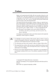
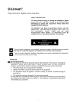
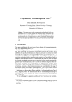
How to configure an Anybus PROFIBUS Slave module with a Siemens Step7 PLC
SCM-7032-026
Rev 2.1
How to configure an Anybus PROFIBUS
Slave module with a Siemens Step7 PLC
www.anybus.com
HMS Industrial Networks AB
Page 1 (30)
How to configure an Anybus PROFIBUS Slave module with a Siemens Step7 PLC
SCM-7032-026
Rev 2.1
Document history
Revision
0.1
Date
2001-04-08
Description
Created
Author
Martin Falkman
1.0
2001-05-02
Released
Martin Falkman
1.1
2001-05-07
Updated according to internal discussions
Martin Falkman
1.2
2001-06-05
Completed according to internal discussions
Leif Malmberg
1.21
2001-06-07
“Company Confidential” footer removed
Martin Falkman
2.0
2007-08-20
Major rewrite
Thorbjörn Palm
2.1
2008-03-06
Updated layout
Thorbjörn Palm
More information about the network and products
The latest manuals and GSD files for the Anybus PROFIBUS modules can be found on the HMS homepage
www.Anybus.com.
The PROFIBUS user organisation has a homepage on the Internet: www.PROFIBUS.com
Several technical guides are available in or via this page.
For information concerning the PLC and the PROFIBUS master system refer to the Siemens homepage
http://www.automation.siemens.com/_en/portal/index.htm.
www.anybus.com
HMS Industrial Networks AB
Page 2 (30)
How to configure an Anybus PROFIBUS Slave module with a Siemens Step7 PLC
SCM-7032-026
Rev 2.1
Contents
1
Applicable Anybus products ...................................................................................................................4
2
Requirements ............................................................................................................................................4
3
Solution overview .....................................................................................................................................5
4
Hardware Configuration .........................................................................................................................6
1.1.
Anybus module settings....................................................................................................................6
1.2.
PLC configuration.............................................................................................................................7
5
PROFIBUS configuration......................................................................................................................10
1.3.
Importing the GSD file ...................................................................................................................10
1.4.
Configuring the Anybus module.....................................................................................................10
5.1.1 I/O configuration ........................................................................................................................12
5.1.2 I/O configuration using data consistency ...................................................................................14
6
Anybus configuration.............................................................................................................................17
1.5.
Communicator configuration ..........................................................................................................18
1.6.
X-gateway configuration ................................................................................................................20
7
Testing .....................................................................................................................................................22
Appendix .........................................................................................................................................................24
Appendix 1 Connecting the bus cable with the D-SUB connector ..............................................................24
Appendix 2 Errors and diagnostics ..............................................................................................................25
The LED:s on the Anybus-S Slave module..............................................................................................25
Diagnostics in Step7.................................................................................................................................27
Appendix 3 Troubleshooting network physics.............................................................................................28
www.anybus.com
HMS Industrial Networks AB
Page 3 (30)
How to configure an Anybus PROFIBUS Slave module with a Siemens Step7 PLC
SCM-7032-026
Rev 2.1
1
Applicable Anybus products
Description
Name / Type
Anybus X-gateway
PROFIBUS
Anybus Communicator
PROFIBUS
Anybus-S Slave DP-V1
PROFIBUS
Anybus-CompactCom
PROFIBUS
Anybus-IC
PROFIBUS
Anybus -PCI
PROFIBUS
2
Requirements
Description
Name / Type
Version
Siemens S7 PLC
CPU 315-2 DP
6ES7 315-2AF02-0AB0
Siemens PLC programming cable
n.a.
n.a.
PC with Siemens PLC programming software
Simatic Step7
5.4.1.0
PROFIBUS slave module
Anybus-S PROFIBUS
1.3
GSD file for the Anybus-S Slave Interface, AnybusPCI, Anybus-IC and the X-gateway Slave Interface
HMS_1013.GSD
1.5
GSD file for the Anybus Communicator
HMS_1803.GSD
1.2
GSD-file for the Anybus CompactCom
HMS_1811.gsd
2.08
GSD-file for the Anybus-IC
HMS_1810.gsd
1.1
Anybus-S Parallel Design Guide
Design Guide
1.13
Anybus-S Fieldbus Appendix PROFIBUS
Fieldbus Appendix
1.2
PROFIBUS standard cable
n.a.
n.a.
PROFIBUS D-SUB contacts
n.a.
n.a.
Power supply 24VDC
n.a.
n.a.
Note: The GSD files can be downloaded at the website www.Anybus.com.
www.anybus.com
HMS Industrial Networks AB
Page 4 (30)
How to configure an Anybus PROFIBUS Slave module with a Siemens Step7 PLC
SCM-7032-026
Rev 2.1
3
Solution overview
Below you find an overview of the system configuration that is described in this document. In this case the
Anybus Slave module is used as an example. Other nodes may be attached to the network, but are not
necessary.
Note: This document is valid for all Anybus Slave PROFIBUS modules. However sections written in italics
and blue text describe the configuration of a specific product.
Figure 1
www.anybus.com
Hardware connection overview.
HMS Industrial Networks AB
Page 5 (30)
How to configure an Anybus PROFIBUS Slave module with a Siemens Step7 PLC
SCM-7032-026
Rev 2.1
4
Hardware Configuration
1.1.
Anybus module settings
Anybus Communicator and the X-gateway:
For the Anybus Communicator and the Anybus X-gateway the address is set by switches. See the description
of the Anybus Slave below. In the case with the Communicator the configuration can also be done by
mailbox commands.
Anybus-PCI, Anybus-IC and the Anybus-CompactCom:
For the Anybus-PCI, IC and CompactCom the address is set by the application. See the respective manual or
addendum for more details.
Anybus-S Slave:
The address setting is done with the two rotary switches on the Anybus Slave module. However in some
applications the application interface is used to set the addresses with software. The address is set to 1 in
this example.
The Anybus-S Slave Interface also has a terminating switch.
•
•
The terminating switch should be set to “ON” if:
o
The module is the last node on the network => physical end of the bus.
o
No other termination is used at this end of the network.
The terminating switch should be set to “OFF” if:
o
There are other nodes on both sides of the module in the network.
o
The module is the last node on the network and a PROFIBUS D-SUB connector is used
which is equipped with a built in and activated termination.
Figure 2
Anybus-S PROFIBUS hardware settings.
Note: The PROFIBUS network must always be terminated at both ends.
www.anybus.com
HMS Industrial Networks AB
Page 6 (30)
How to configure an Anybus PROFIBUS Slave module with a Siemens Step7 PLC
SCM-7032-026
Rev 2.1
1.2.
PLC configuration
The PLC system hardware configuration is done solely with the Siemens Step7 tool.
In order to configure the bus it is necessary to set up the PLC and master hardware first. In this example we
are using an S7315-2 CPU and a 2A power supply with a standard rack. Start the Simatic software and start a
new project. Right click on PROFIBUS and insert a Simatic 300 Station as shown below.
Figure 3
Inserting a new PLC.
Then double click on the new SIMATIC 300 station and on Hardware to open the hardware configuration.
Figure 4
www.anybus.com
Opening the hardware configuration. The right figure shows the network when completed.
HMS Industrial Networks AB
Page 7 (30)
How to configure an Anybus PROFIBUS Slave module with a Siemens Step7 PLC
SCM-7032-026
Rev 2.1
DP, PROFIBUS master
Module.
Figure 5
Adding the hardware to the configuration.
Add a rail, the power module and the PLC as shown above. The next step is to double click on the DP,
PROFIBUS master, module to configure the PROFIBUS network. Click on properties in the dialogue as
shown below.
Figure 6
Changing the properties of the PROFIBUS module and defining a new PROFIBUS network.
Then click on new to define a new network.
www.anybus.com
HMS Industrial Networks AB
Page 8 (30)
How to configure an Anybus PROFIBUS Slave module with a Siemens Step7 PLC
SCM-7032-026
Rev 2.1
Figure 7
Configuring the properties of the PROFIBUS network.
Select the desired settings and press OK. When the PLC hardware is set up it will look like described in the
figure below.
Figure 8
www.anybus.com
PLC with empty bus.
HMS Industrial Networks AB
Page 9 (30)
How to configure an Anybus PROFIBUS Slave module with a Siemens Step7 PLC
SCM-7032-026
Rev 2.1
5
PROFIBUS configuration
1.3.
Importing the GSD file
It is necessary to import the Anybus GSD-file to the configuration tool in order to include the Anybus
Module. In this case an Anybus Slave module is added as a slave in the network. The GSD-files can be
downloaded at HMS 1 webpage.
Note: After downloading the GSD-file has to be renamed. The SIMATIC software does not accept file
names longer then 12 characters.
Figure 9
1.4.
Install a new GSD file in "HW Config".
Configuring the Anybus module
The Anybus module can be found in the hardware catalogue after the GSD file has been imported.
Figure 10 The Anybus module in the Hardware Catalogue.
It is now possible to include the Anybus slave in the network.
1
www.Anybus.com
www.anybus.com
HMS Industrial Networks AB
Page 10 (30)
How to configure an Anybus PROFIBUS Slave module with a Siemens Step7 PLC
SCM-7032-026
Rev 2.1
Open up the “Anybus-S PDP” entry in the hardware catalogue and drag and drop the Anybus module on to
the network, see description in Figure 11.
Figure 11 Drag and drop the Anybus module to the network.
It is then necessary to configure the Anybus module itself. The only configuring to be done is setting up the
node address, input and output data area sizes and offset address.
In Figure 12 it is shown how to edit the node address. The edit-window for the node address is opened by
doing the click sequence n, o, p. At p it is possible to set the desired node address. The address set here
must equal the address set on the Anybus-S module, see the chapter 1.1 Anybus module setting.
Figure 12 Adjusting the node address in HW Config.
www.anybus.com
HMS Industrial Networks AB
Page 11 (30)
How to configure an Anybus PROFIBUS Slave module with a Siemens Step7 PLC
SCM-7032-026
Rev 2.1
5.1.1
I/O configuration
The choice of module(s) you like to use depends on what your application demand is. It is possible to choose
these modules freely and to compose the I/O sizes needed, se examples below in table 1.
Bytes needed by the application
Modules to use
4 In + 2 Out
4 In + 2 Out
7 In + 12 Out
4 In + 2 In + 1 In + 8 Out + 4 Out
32 In + 32 Out
32 In/Out
68 In
64 In + 4 In
Note: Reading or writing more than four bytes consistent data from the I/O image, see the next chapter. For
all Anybus PROFIBUS modules except the Anybus-CompactCom, more than 2 bytes of consistent data is
only supported when using the Universal module.
Expand the Anybus-S PDP tree in the navigation list to the right. The modules are then composed together in
the “module list” of the Anybus as shown in the figure below.
Figure 13 Selecting In and Out modules with “Drag and Drop”.
By double clicking on a module in the “module list” it is possible to set the offset addresses. See example in
Figure 14.
www.anybus.com
HMS Industrial Networks AB
Page 12 (30)
How to configure an Anybus PROFIBUS Slave module with a Siemens Step7 PLC
SCM-7032-026
Rev 2.1
Figure 14 Adjusting the offset address.
The offset addresses can be chosen freely but certain restrictions may apply depending on what CPU is used.
When all the above settings are done it is possible to perform a download of the configuration to the PLC.
Press the Save and Compile button and then the download button.
Download button
Save and Compile button
Figure 15 Downloading the configuration to the PLC.
The bus will then go online and start data exchange when the PLC is set to run mode.
www.anybus.com
HMS Industrial Networks AB
Page 13 (30)
How to configure an Anybus PROFIBUS Slave module with a Siemens Step7 PLC
SCM-7032-026
Rev 2.1
5.1.2
I/O configuration using data consistency
The S7 PLC can read out one, two or four bytes consistent from the I/O-image directly by accessing the data
as a Byte, a Word or a Double Word as described in the previous chapter, 5.1.1. This is the normal usage and
fits most applications. However if it is required to read out other consistent data areas it is necessary to use
the System Function Blocks SFC14 and SFC15. Below follows a description of these function blocks.
The first thing that has to be done is to specify the consistent data area in the hardware configuration. The
“Universal Module” can be selected with “drag and drop” as shown in Figure 16.
Figure 16 Selecting the Universal Module for consistent data transfer.
www.anybus.com
HMS Industrial Networks AB
Page 14 (30)
How to configure an Anybus PROFIBUS Slave module with a Siemens Step7 PLC
SCM-7032-026
Rev 2.1
In Figure 17 it is shown how to set the properties of the Universal Module. This window is opened by double
clicking on the Universal Module line in the list of selected modules. The desired data type (In, Out, or
In/Out) is set with the list box shown at n. Then the offset, length, unit and consistency settings can be done
as shown at o. In the example below the output data length is set to 12 bytes and the input data length set to
38 bytes with consistency over the total length. The address offsets are set to 46 respective 92.
The “Data for Specific Manufacturer” shown at p is not used unless the device manufacturer specifies this.
Figure 17 Specifying the properties for the Universal Module.
To read out the consistent data specified in Figure 16 and Figure 17 a PLC program has to be written that
uses SFC14 and SFC15. An example of this is shown in Figure 18. These two SFC:s are included in the
Step7 standard package and they also have to be imported into the active project. They can be copied from
the “Standard Library” or from the CPU online. Refer to the Step7 documentation for details regarding this.
The function blocks ensure that data consistency is secured over the complete data length. Where the data is
to be read or put in the process image is decided in the hardware configuration, see Figure 17.
www.anybus.com
HMS Industrial Networks AB
Page 15 (30)
How to configure an Anybus PROFIBUS Slave module with a Siemens Step7 PLC
SCM-7032-026
Rev 2.1
SFC14 Input data:
The purpose of SFC14 is to read out the data from the In area of the process image and then copy the data to
another storage location.
LADDR: specifies the start byte address of the data to be read. The value is entered in Hex. In this case the
start byte address is 92 (=5C Hex) which can be found at o in Figure 17.
RET_VAL: Storage location for error messages. This is a Word, in this case MW4.
RECORD: This is where the data is copied to. In this case it is copied to memory byte 10 to 47. (i.e. MB10MB47). The length must equal the length set at o in Figure 17.
SFC15 Output data:
The Purpose of SFC15 is to read the data from any storage location and then copy it to the Out area of the
process image.
LADDR: specifies the start byte address of the data to be sent. The value is entered in Hex. In this case the
start byte address is 46 (=2E Hex) which can be found at o in Figure 17.
RET_VAL: Storage location for error messages. This is a Word, in this case MW6.
RECORD: This is where the data is read from. In this case it is read from memory byte 48-59. (i.e. MB48MB59). The length must equal the length set at o in Figure 17.
The data can then be processed as desired (i.e. as byte, word, double word or bit wise) at the other storage
location specified at RECORD.
In the example below (Figure 18) it is described how the PLC program can be done.
Figure 18 The use of the SFC14 and SFC15 in the PLC program.
By highlighting the SFC in the LAD-editor and then pressing “F1” the help function will start and display
extended information such as error codes and syntax examples.
www.anybus.com
HMS Industrial Networks AB
Page 16 (30)
How to configure an Anybus PROFIBUS Slave module with a Siemens Step7 PLC
SCM-7032-026
Rev 2.1
6
Anybus configuration
The Anybus product has to be configured for the same I/O sizes as set up in the PROFIBUS configuration.
Note: The I/O sizes are depending on the application, the configured I/O sizes in this chapter are just
examples.
Anybus-S Slave Interface and the Anybus PCI card:
The Anybus Slave Interface and the Anybus PCI card are configured by mailbox commands. Refer to
respective Fieldbus Appendix for details.
Anybus-IC:
The Anybus-IC is configured by the User Interface using for example the Windows Hyper Terminal. Refer to
the Design Guide for details.
Anybus CompactCom:
The Anybus CompactCom is configured by messages send by the application. Refer to the Design Appendix
for details.
Anybus Communicator and the Anybus X-gateway:
The configuration of the Anybus Communicator and the Anybus X-gateway is described in separate sections
below.
www.anybus.com
HMS Industrial Networks AB
Page 17 (30)
How to configure an Anybus PROFIBUS Slave module with a Siemens Step7 PLC
SCM-7032-026
Rev 2.1
1.5.
Communicator configuration
Start the Anybus Communicator Config Tool. The module is configured for PROFIBUS and generic data
mode as shown below. The I/O size is set to 2 bytes in this example.
Figure 19 Bus type setup.
Figure 20 Protocol mode configuration.
The sub network is configured as seen in the figure below. The values are left at the default except for the
update time for the produce transaction, in this case it is set to 500 ms. Also the bit rate is set to 19200 bits/s.
www.anybus.com
HMS Industrial Networks AB
Page 18 (30)
How to configure an Anybus PROFIBUS Slave module with a Siemens Step7 PLC
SCM-7032-026
Rev 2.1
Figure 21 Configuration of sub network.
Two bytes of I/O data are used as shown in the figure below.
Figure 22 Configuration of I/O data.
www.anybus.com
HMS Industrial Networks AB
Page 19 (30)
How to configure an Anybus PROFIBUS Slave module with a Siemens Step7 PLC
SCM-7032-026
Rev 2.1
1.6.
X-gateway configuration
Use the HyperTerminal on a PC and configure the X-gateway, connect a serial cable between the PC and
the config port on the X-gateway. Open the “File” menu and click on new, choose the desired COM port and
click on OK. The following window will appear.
Figure 23 Configuring the connection in the HyperTerminal.
Make sure the settings are identical to those shown in the window above. An alternative method is to
download the HyperTerminal session file from HMS website 2 , double click on it and select COM port.
Connect and press ESC and the following menu will appear.
Figure 24 Anybus X-gateway Main menu.
Press 6 and enter the desired configuration. The I/O sizes are depending on the application, the I/O sizes
used in this case are just an example.The figure below shows an example; in this case a PROFIBUS Slave/
Ethernet IP X-gateway is used. The PROFIBUS Slave is configured for 10 bytes of I/O data and the
EtherNet/IP Slave for 8 bytes of I/O data.
2
www.Anybus.com
www.anybus.com
HMS Industrial Networks AB
Page 20 (30)
How to configure an Anybus PROFIBUS Slave module with a Siemens Step7 PLC
SCM-7032-026
Rev 2.1
Figure 25 The X-gateway configuration.
www.anybus.com
HMS Industrial Networks AB
Page 21 (30)
How to configure an Anybus PROFIBUS Slave module with a Siemens Step7 PLC
SCM-7032-026
Rev 2.1
7
Testing
To verify that the Anybus module and the PLC are correctly configured it is possible to monitor the Input
and Output modules in the Hardware config in the SIMATIC software. An Anybus Communicator with a
loop back dongle at the serial port is used for the test. In the HW Config window, mark the Output module
and open the PLC menu and select Monitor/Modify.
Figure 26 Opening the monitor/modify window.
Then enter a value in the Output module. In this case 45 is entered in the space column Modify value. To
accept press the Modify value button.
www.anybus.com
HMS Industrial Networks AB
Page 22 (30)
How to configure an Anybus PROFIBUS Slave module with a Siemens Step7 PLC
SCM-7032-026
Rev 2.1
Figure 27 Modifying the Output module.
In the same way the Input module can be monitored. Mark the Input module a open the Monitor/Modify
window. Using the correct settings the value 45 will be seen in the Input module after pressing the Status
Value button.
Figure 28 Monitoring the Input module.
www.anybus.com
HMS Industrial Networks AB
Page 23 (30)
How to configure an Anybus PROFIBUS Slave module with a Siemens Step7 PLC
SCM-7032-026
Rev 2.1
Appendix
Appendix 1 Connecting the bus cable with the D-SUB
connector
The Anybus module can be mounted with several types of bus connectors. The standard connector shown
below should be used in this example.
Figure 29 Standard PROFIBUS D-SUB connector
Figure 30 Bus connector with built-in terminating resistors and series inductors
www.anybus.com
HMS Industrial Networks AB
Page 24 (30)
How to configure an Anybus PROFIBUS Slave module with a Siemens Step7 PLC
SCM-7032-026
Rev 2.1
Appendix 2 Errors and diagnostics
The LED:s on the Anybus-S Slave module
The LED:s on the Anybus-S Slave module have the meaning shown in Figure 31.
Figure 31 Indication LEDs on the Anybus-S module
LED #
Name
n
o
Not used
p
On-Line
Off-Line
Colour
Green
Red
Meaning
Indicates that the module is On-Line on the
fieldbus.
Solid Green - Module is On-Line and data
exchange is possible.
Turned Off - Module is not On-Line
Indicates that the module is Off-Line on the
fieldbus.
Solid Red - Module is Off-Line and no data
exchange is possible.
Turned Off - Module is not Off-Line
q
Fieldbus
Diagnostics
Red
Indicates certain faults on the Fieldbus side.
Flashing Red 1 Hz - Error in configuration:
IN and/or OUT length set during initialisation
of the module is not equal to the length set
during configuration of the network.
Flashing Red 2 Hz - Error in User Parameter
data: The length/contents of the User
Parameter data set during initialisation of the
module is not equal to the length/contents set
during configuration of the network.
Flashing Red 4 Hz - Error in initialisation of
the PROFIBUS communication ASIC.
Corrective actions
No actions needed
Check hardware, i.e. cable
connection, baudrate setting
etc.
Check hardware configuration
in Step7
Check hardware configuration
in Step7
If Flashing Red 4 Hz consult
HMS
Turned Off - No diagnostics present
www.anybus.com
HMS Industrial Networks AB
Page 25 (30)
How to configure an Anybus PROFIBUS Slave module with a Siemens Step7 PLC
SCM-7032-026
Rev 2.1
Watchdog LED
There is also a bicolour (red/green) watchdog LED on the circuit board, indicating the module status
according to Figure 32.
Figure 32 Wtchdog LED position.
Watchdog function
Colour
Frequency
ASIC and FLASH ROM check fault
Red
2Hz
Module not initialised
Green
2Hz
Module initialised and running OK
Green
1Hz
RAM check fault
Red
1Hz
DPRAM check fault
Red
4Hz
www.anybus.com
HMS Industrial Networks AB
Page 26 (30)
How to configure an Anybus PROFIBUS Slave module with a Siemens Step7 PLC
SCM-7032-026
Rev 2.1
Diagnostics in Step7
Step7 and the HW Config program provide diagnostic possibilities via the PROFIBUS master over the
network. Start with going online by clicking on the button n in Figure 33. Then right-click on o and chose
“Module Information” and the diagnostic function will be started. The window p will be displayed and
available diagnostics can be read out.
What diagnostics that is available depends on the application. In standard mode there are no application
specific diagnostics available. All the standard PROFIBUS diagnostics are supported and information
regarding this can be found in the online documentation of Step7. Application specific diagnostics, error
codes etc. can be found in the documentation of the application.
If the message shown in the window p appears the reason can be the following:
•
The Anybus module is not attached properly to the PROFIBUS network. Check cabling.
•
The node address of the Anybus module does not match the address set in the Simatic Config
program.
•
The Anybus module is faulty and does not start up properly. Check the LEDs on the Anybus module.
Figure 33 Step7 Hardware diagnostics.
www.anybus.com
HMS Industrial Networks AB
Page 27 (30)
How to configure an Anybus PROFIBUS Slave module with a Siemens Step7 PLC
SCM-7032-026
Rev 2.1
Appendix 3 Troubleshooting network physics
The most common failure when the diagnostic tool reports “nonsense” is physical errors on the network like
cable connect errors, miss contact, wrong termination etc. Some simple ways to find these errors will be
mentioned here.
Data errors can occur if the PROFIBUS cable is incorrectly attached to the bus connectors. Such basic errors
can be detected and remedied with the simple test method described below. The test method shown
schematically in Figure 34 allows you to detect data wires which are swapped over in the bus connectors.
During the test, the bus connectors must not be connected to any PROFIBUS devices. In addition, all bus
terminating resistors should be removed or disabled. The tests require two 9 pin female Sub-D test
connectors. Test connector 1 is provided with a single pole changeover switch, the moving contact of which
is connected to the shield (case) of the test connector. The two fixed contacts are connected to pin 3 (data
wire B) and pin 8 (data wire A), respectively. Test connector 2 is used to connect an Ohmmeter to the bus.
During the cable tests, the two test connectors 1 and 2 are initially plugged into the two bus connectors at
each end of the bus segment. The following tests can be made by taking measurements between the contacts
3 and 8 and the shield of test connector 2 while operating the changeover switch on test connector 1:
•
Data cable swapped over
•
Open circuit of one of the data cables
•
Open circuit of the cable shield
•
Short circuit between the data cables
•
Short circuit between the data cables and the cable shield
•
Additional bus terminating resistors inserted unintentionally
www.anybus.com
HMS Industrial Networks AB
Page 28 (30)
How to configure an Anybus PROFIBUS Slave module with a Siemens Step7 PLC
SCM-7032-026
Rev 2.1
Figure 34 Troubleshooting the PROFIBUS network.
Carrying out the tests
• Configuration A: Set switch of test connector 1 to position 3 (connects pin 3 to the screen). Connect
ohmmeter to test connector 2 between pin 3 and the screen.
• Configuration B: Set switch of test connector 1 to position 8 (connects pin 8 to the screen). Connect
ohmmeter to test connector 2 between pin 8 and the screen.
• Configuration C: Set switch of test connector 1 to position 3 (connects pin 3 to the screen). Connect
ohmmeter to test connector 2 between pin 8 and the screen.
• Configuration D: Switch position of test connector 1 is not important. Connect ohmmeter to test
connector 2 between pin 3 and pin 8.
Warning: The measured value can be falsified if the ohmmeter connections are touched.
www.anybus.com
HMS Industrial Networks AB
Page 29 (30)
How to configure an Anybus PROFIBUS Slave module with a Siemens Step7 PLC
SCM-7032-026
Rev 2.1
Test 1:
Figure 35 Test procedure 1.
x=110ohm/km
Test 2: Same as test 1 except configuration A and configuration B are exchanged, i.e. start with
configuration B.
Test 3: Too many bus terminating resistors inserted.
Figure 36 Test procedure 3.
In order to assess the measurements you make, it is necessary to know the loop resistance of the bus cable
segment. This is dependent on the cable type used and the installed cable length. The location of a fault can
be determined without opening up the bus connectors by unplugging test connector 1 and plugging it into
another bus connector which is closer to test connector 2 while carrying out repeated Ohmmeter
measurements at test connector 2
www.anybus.com
HMS Industrial Networks AB
Page 30 (30)