1
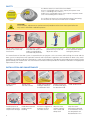
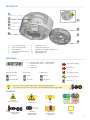
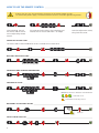
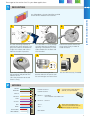
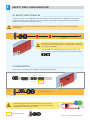
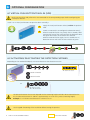
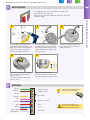
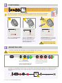
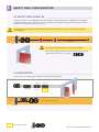
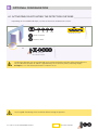
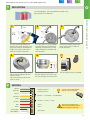
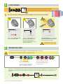
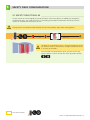
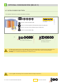
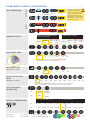
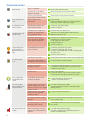
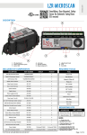
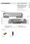
EN
A
E
B L
E S
O
A C C
R
D
A
A
E
W I
T H
50
186
DIN
C
E R L AU
BT
W I
T H
E
C
N
A
N
H
H
N
Z I E RUNG
FI
TI
E
N
N
C
EN
E
05
160
R
Z
N
E R L AU
BT
Z I E RUNG
FI
TI
Z
R
C
E
A
B L
E S
O
A C C
R
D
A
®
LZR -P110
LASER SCANNER FOR PEDESTRIAN DOORS
User’s Guide for product version 0600 and higher
See product label for serial number
SLIDING
SWINGING
REVOLVING
1
SAFETY
The device contains IR and visible laser diodes.
IR laser: wavelength 905nm; max. output pulse power 75W
(Class 1 according to IEC 60825-1)
Visible laser: wavelength 650nm; max. output CW power 3mW
(Class 3R according to IEC 60825-1)
The visible laser beams are inactive during normal functioning.
The installer can activate the visible lasers if needed.
CAUTION!
Use of controls, adjustments or performance of procedures other than those specified herein
may result in hazardous radiation exposure.
Do not look into the laser
emitter or the visible red
laser beams.
The warranty is void if
unauthorized repairs are
made or attempted by
unauthorized personnel.
Only trained and qualified
personnel may install and
adjust the sensor.
Test the good functioning
of the installation before
leaving the premises.
The manufacturer of the door system is responsible for carrying out a risk assessment and installing the sensor and the
door system in compliance with applicable national and international regulations and standards on door safety and if
applicable, the machinery directive 2006/42/EC. Other use of the device is outside the permitted purpose and can not be
guaranteed by the manufacturer. The manufacturer cannot be held responsible for incorrect installations or inappropriate
adjustments of the sensor.
INSTALLATION AND MAINTENANCE
Avoid extreme
vibrations.
Do not cover
the front screens.
Avoid exposure to
Avoid direct exposure
sudden and extreme to high pressure
temperature changes. cleaning.
2
Avoid moving objects
and light sources in
the detection field.
Avoid the presence
of smoke and fog in
the detection field.
Avoid condensation.
Do not use aggressive
products to clean
the front screens.
Wipe the front
screens regularly
with a clean and
damp cloth.
Keep the sensor
permanently powered
in environments where
the temperature can
descend below -10°C.
DESCRIPTION
1
2
3
4
5
7
8
6
9
10
1.
2.
3.
4.
5.
6.
7.
8.
9.
10.
laser sweep emission
laser sweep reception
LED-signals (4)
screws for position lock (2)
connector
protection cover
visible laser beams (3)
notches for tilt angle adjustment (2)
adjustable bracket
cable conduits (4)
LED-SIGNAL
1
3
2
4
DETECTION LEDs
detection
no detection
1.
2.
3.
4.
Detection LED: relay 1 - optional field
Detection LED: relay 2 - safety field
Error LED
Power LED
ERROR LED
POWER LED
error
power
no error
LED flashes quickly
LED flashes
LED flashes slowly
LED flashes once
1x
no power
LED is off
All 4 LEDs can be switched off and on again by remote control.
This can be useful in cases where the sensor should not draw any attention.
SYMBOLS
B L
E S
O
A C C
R
D
E
R
Z I E RUNG
FI
TI
N
Z
A
N
A
B L
E S
E R L AU
BT
O
A C C
R
D
A
A
W I
T H
E
C
E
E
N
N
E
N
A
A
05
50
160
186
DIN
W I
T H
W I
T H
W I
T H
E
O
A C C
C
N
B L
E S
EN
E
E R L AU
BT
C
Remote control
sequence
A
A
DE
R
N
N
H
Caution!
Laser radiation
N
Z I E RUNG
FI
TI
C
H
E
R
H
C
Z
E
A
C
N
H
E R L AU
BT
Z I E RUNG
FI
TI
R
C
E
N
A
Z
N
05
50
160
186
EN
DIN
E R L AU
BT
Z I E RUNG
FI
TI
Z
R
C
E
A
B L
E S
O
A C C
R
D
A
Attention!
Important!
Tip
Info
Not
According according
to
to
DIN 18650/EN 16005
Possible
remote control
adjustments
Important
remote control
sequence
Factory
values
3
HOW TO USE THE REMOTE CONTROL
4 hours after last use, the sensor locks the access to the remote control session.
Cut and restore power supply. The remote control session is accessible again during 4 hours.
After unlocking, the red
LED flashes and the sensor
can be adjusted by remote
control.
If the red LED flashes quickly after unlocking, you
need to enter an access code from 1 to 4 digits.
4h
To end an adjustment session,
always lock the sensor.
SAVING AN ACCESS CODE
The access code is recommended for sensors installed close to each other.
DELETING AN ACCESS CODE
Enter the existing code
ADJUSTING ONE OR MORE PARAMETERS
CHECKING A VALUE
x
NUMBER OF FLASHES = VALUE OF THE PARAMETER
4x
3x
1x
2x
= field width: 4.2 m
= field width is defined by teach-in
RESTORING TO FACTORY VALUES
teach-in
SAFETY FIELD TEACH-IN
3s
4
max. 30 s
Please go to the section that fits your door application:
1
P. 5
P. 9
P. 13
SLIDING
SWINGING
REVOLVING
MOUNTING
1
2
10 cm
3
45°
Use the mounting template to
position the sensor correctly. The
grey area indicates the detection
range. Drill 4 holes and make a
hole for the cable if possible.
4
45°
Pass the cable +/- 10 cm though
the cable opening. If drilling an
opening is not possible, use the
cable conduits on the back side
of the bracket.
Position the bracket and fasten
the 4 screws firmly in order to
avoid vibrations.
5
Open the protection cover, plug
the connector and position the
cable in the slit.
Close the protection cover and
fasten it firmly.
2
LZR-P110 ON SLIDING DOORS
On sliding doors, the LZR should be installed
on one of the two door frame corners.
Position the housing on the
bracket and turn the sensor until
the two triangles are face to face.
Use the LBA accessory if needed.
WIRING
GREEN
BROWN
+
-
WHITE
POWER SUPPLY +
POWER SUPPLY -
Use the Power Supply Module
(24V DC, 0.75 A) if needed.
RELAY 1 - OPENING
VIA VIRTUAL PUSH BUTTON
YELLOW
PINK
RELAY 2 - SAFETY
VIOLET
RED
BLUE
WHITE/RED
WHITE/BLUE
+
-
TEST +
TEST -
Door control without test:
connect red and blue wires to
power supply (no polarity)
NOT USED
5
3
POSITIONING
Unlock the sensor and activate the visible laser beams
in order to position the curtains parallell to the door.
The visible laser beams indicate approximately the postion of the curtain closest to the door.
90°
They stay activated for 15 minutes or can be turned off the same way they were activated.
0°
45°
1
2
door frame
door frame
door frame
5 cm
visible laser beam
Adjust the lateral position
of the detection field.
4
visible laser beam
visible laser beam
Lock the position of the mounting
bracket to avoid malfunctioning in
case of extreme vibrations.
Adjust the tilt angle of the
detection field with the hex
key. The visible laser beam
should be positioned 5 cm in
front of the door frame.
Avoid reflections of the visible
laser beams on the door frame.
MOUNTING SIDE
Check the mounting side and change the corresponding value if necessary.
Stay outside of the detection field to avoid disturbances.
B L
E S
O
A C C
R
D
E
A
B L
E S
O
A C C
R
D
E
R
Z I E RUNG
FI
TI
N
A
E
A
left
right
N
A
B L
E S
O
A C C
R
D
A
E
W I
T H
C
C
E
E
W I
T H
E
C
N
N
A
A
50
05
186
160
EN
DIN
N
N
E R L AU
BT
W I
T H
E
E R L AU
BT
C
N
A
N
H
N
right
Z I E RUNG
FI
TI
H
H
E
left
R
Z
E
H
C
Z
A
E R L AU
BT
N
W I
T H
Z I E RUNG
FI
TI
50
05
186
160
EN
DIN
N
R
C
E
Z
A
Z
N
E R L AU
BT
Z I E RUNG
FI
TI
C
R
C
E
A
B L
E S
O
A C C
R
D
A
centre
WITH BACKGROUND
WITHOUT BACKGROUND
The sensor memorizes the floor as
reference point and signals a fault
when its orientation is changed.
No reference point
A teach-in is launched: the sensor learns its environment and automatically determines the detection field(s).
Both RED LEDs flash slowly. The 3 visible laser beams automatically light up during the 30 seconds of the
teach-in.
Ex:
3s
6
LZR-P110 ON SLIDING DOORS
max. 30 s
5
SAFETY FIELD CONFIGURATION
5.1 SAFETY FIELD TEACH-IN
Launch a teach-in after changing the sensor position or when new objects are added to or changed in
the detection zone. The sensor will learn its surroundings and adapt the detection field shape to these.
Objects in the detection field will be cut out.
During teach-in, the detection field should be free of snow buildups, heavy rain, snowfall, fog or other
moving objects.
3s
max. 30 s
The door has to complete at least 1 full cycle (open + close) for
the sensor to learn its environment. During this operation there
is no safety on the door!
Once the door has completed its cycle, you can wait for the
teach-in process to finish or lock the sensor by remote control:
5.2 FIELD WIDTH
After teach-in, the field width should be reduced by remote control.
MAX
MIN
no field
Ex:
0.5 m
5.0 m
for a field width of 4.2 m
Z I E RUNG
FI
TI
N
A
E
R
Z I E RUNG
FI
TI
N
A
N
A
B L
E S
O
A C C
R
D
A
E
N
N
E
C
C
E
E
W I
T H
W I
T H
50
05
186
160
EN
DIN
N
The distance between the inner curtains of the 2 sensors must
ensure the detection of the CA testbody (700 x 300 x 200 mm)
according to EN 16005 and DIN 18650.
E R L AU
BT
E R L AU
BT
H
H
C
Z
Z
R
C
E
A
B L
E S
O
A C C
R
D
A
FACTORY VALUES
LZR-P110 ON SLIDING DOORS 7
6
OPTIONAL CONFIGURATION
6.1 VIRTUAL PUSH BUTTON TEACH-IN (VPB)
Make sure the white and yellow wires are connected to the corresponding inputs before configuring the
virtual push buttons.
Install 1 or 2 virtual push buttons to open the door «manually».
1
Apply the vitual push button sticker(s) within the optional
field.
2
Launch a VPB teach-in to configure the detection zone(s).
When the red LED flashes very slowly after 3 seconds, hold
your hand in front of the sticker to learn the detection zone.
The green LED flashes 3x to confirm the selection.
When the red LED flashes again, learn a second (max. 2)
detection zone or wait until the LED switches to green.
3
3s
6.2 ACTIVATING/ DEACTIVATING THE DETECTION CURTAINS
Depending on the needed field depth, activate or deactivate the detection curtains.
X
X
X
X
λ1
λ2
λ3
λ4
All curtains are active
curtain is inactive
λ1
λ2
curtain is active
λ3
λ4
Ex:
λ1 + λ 2 are active
λ 3 + λ4 are inactive
The distance between the curtains depends on the mounting height and side. When mounted on the
left, the distance between λ1 and λ4 is approximately 10 cm for every meter (mounting height).
Example: at 5 m the distance between λ1 and λ4 is 50 cm.
Test the good functioning of the installation before leaving the premises.
8
LZR-P110 ON SLIDING DOORS
FACTORY VALUES
Please go to the section that fits your door application:
1
P. 5
P. 9
P. 13
SLIDING
SWINGING
REVOLVING
MOUNTING
1
2
10 cm
45°
Use the mounting template to
position the sensor correctly. The
grey area indicates the detection
range. Drill 4 holes and make a
hole for the cable if possible.
3
45°
Pass the cable +/- 10 cm though
the cable opening. If drilling an
opening is not possible, use the
cable conduits on the back side
of the bracket.
Position the bracket and fasten
the 4 screws firmly in order to
avoid vibrations.
5
4
Open the protection cover, plug
the connector and position the
cable in the slit.
Close the protection cover and
fasten it firmly.
2
LZR-P110 ON SWINGING DOORS
On swinging doors, the LZR should be installed in the
upper corner of the door leaf.
Make sure that the sensor does not touch the wall when
the door is open.
Position the housing on the
bracket and turn the sensor until
the two triangles are face to face.
WIRING
GREEN
BROWN
+
-
WHITE
POWER SUPPLY +
POWER SUPPLY -
Use the Power Supply Module
(24V DC, 0.75 A) if needed.
NOT USED
YELLOW
PINK
RELAY 2 - SAFETY
VIOLET
RED
BLUE
WHITE/RED
WHITE/BLUE
+
-
TEST +
TEST -
Door control without test:
connect red and blue wires to
power supply (no polarity)
NOT USED
9
3
POSITIONING
Unlock the sensor and activate the visible laser beams
in order to position the curtains parallell to the door.
90°
The visible laser beams indicate approximately the postion of the curtain closest to the door.
They stay activated for 15 minutes or can be turned off the same way they were activated.
45°
0°
1
2
door axis
door axis
door axis
10 cm
visible laser beam
Adjust the lateral position
of the detection field.
4
visible laser beam
visible laser beam
Lock the position of the mounting
bracket to avoid malfunctioning in
case of extreme vibrations.
Adjust the tilt angle of the
detection field with the hex
key. The visible laser beam
should be positioned 10 cm in
front of the door axis.
Avoid reflections of the visible
laser beams on the door wing.
MOUNTING SIDE
Check the mounting side and change the corresponding value if necessary.
Stay outside of the detection field to avoid disturbances.
B L
E S
O
A C C
R
D
E
A
B L
E S
O
A C C
R
D
E
R
Z I E RUNG
FI
TI
N
A
E
A
left
right
N
A
B L
E S
O
A C C
R
D
A
E
W I
T H
C
C
E
E
W I
T H
E
C
N
N
A
A
50
05
186
160
EN
DIN
N
N
E R L AU
BT
W I
T H
E
E R L AU
BT
C
N
A
N
H
N
right
Z I E RUNG
FI
TI
H
H
E
left
R
Z
E
H
C
Z
A
E R L AU
BT
N
W I
T H
Z I E RUNG
FI
TI
50
05
186
160
EN
DIN
N
R
C
E
Z
A
Z
N
E R L AU
BT
Z I E RUNG
FI
TI
C
R
C
E
A
B L
E S
O
A C C
R
D
A
centre
WITH BACKGROUND
WITHOUT BACKGROUND
The sensor memorizes the floor as
reference point and signals a fault
when its orientation is changed.
No reference point
A teach-in is launched: the sensor learns its environment and automatically determines the detection field(s).
Both RED LEDs flash slowly. The 3 visible laser beams automatically light up during the 30 seconds of the
teach-in.
Ex:
3s
10 LZR-P110 ON SWINGING DOORS
max. 30 s
5
SAFETY FIELD CONFIGURATION
5.1 SAFETY FIELD TEACH-IN
Launch a teach-in after changing the sensor position or when new objects are added to or changed in
the detection zone. The sensor will learn its surroundings and adapt the detection field shape to these.
Objects in the detection field will be cut out.
During teach-in, the detection field should be free of snow buildups, heavy rain, snowfall, fog or other
moving objects.
3s
max. 30 s
During this operation there is no safety on the door!
Wait for the teach-in process to finish or lock the sensor by
remote control after min. 3 seconds:
5.2 FIELD WIDTH
After teach-in, the field width should be reduced by remote control.
MAX
MIN
no field
Ex:
0.5 m
5.0 m
for a field width of 4.2 m
FACTORY VALUES
LZR-P110 ON SWINGING DOORS 11
6
OPTIONAL CONFIGURATION
6.1 ACTIVATING/ DEACTIVATING THE DETECTION CURTAINS
Depending on the needed field depth, activate or deactivate the detection curtains.
X
X
X
X
λ1
λ2
λ3
λ4
All curtains are active
curtain is inactive
curtain is active
λ1
λ2
λ3
λ4
Ex:
λ1 + λ 2 are active
λ 3 + λ4 are inactive
The distance between the curtains depends on the mounting height and side. When mounted on the
left, the distance between λ1 and λ4 is approximately 10 cm for every meter (mounting height).
Example: at 5 m the distance between λ1 and λ4 is 50 cm.
Test the good functioning of the installation before leaving the premises.
12 LZR-P110 ON SWINGING DOORS
FACTORY VALUES
Please go to the section that fits your door application:
1
P. 5
P. 9
P. 13
SLIDING
SWINGING
REVOLVING
MOUNTING
1
2
10 cm
3
45°
Use the mounting template to
position the sensor correctly. The
grey area indicates the detection
range. Drill 4 holes and make a
hole for the cable if possible.
4
45°
Pass the cable +/- 10 cm though
the cable opening. If drilling an
opening is not possible, use the
cable conduits on the back side
of the bracket.
Position the bracket and fasten
the 4 screws firmly in order to
avoid vibrations.
5
Open the protection cover, plug
the connector and position the
cable in the slit.
Close the protection cover and
fasten it firmly.
2
LZR-P110 ON REVOLVING DOORS
On revolving doors, the LZR should be installed in the
upper corner of the door leaf.
Position the housing on the
bracket and turn the sensor until
the two triangles are face to face.
Use the LBA accessory if needed.
WIRING
GREEN
BROWN
+
-
WHITE
POWER SUPPLY +
POWER SUPPLY -
Use the Power Supply Module
(24V DC, 0.75 A) if needed.
RELAY 1 - OPTIONAL - SLOWDOWN
YELLOW
PINK
RELAY 2 - SAFETY - STOP
VIOLET
RED
BLUE
WHITE/RED
WHITE/BLUE
+
-
TEST +
TEST -
Door control without test:
connect red and blue wires to
power supply (no polarity)
NOT USED
13
3
POSITIONING
Unlock the sensor and activate the visible laser beams
in order to position the curtains parallell to the door.
90°
The visible laser beams indicate approximately the postion of the curtain closest to the door.
They stay activated for 15 minutes or can be turned off the same way they were activated.
1
45°
0°
2
door axis
door axis
door axis
10 cm
visible laser beam
Adjust the lateral position
of the detection field.
4
visible laser beam
visible laser beam
Lock the position of the mounting
bracket to avoid malfunctioning in
case of extreme vibrations.
Adjust the tilt angle of the
detection field with the hex
key. The visible laser beam
should be positioned 10 cm in
front of the door axis.
Avoid reflections of the visible
laser beams on the door wing.
MOUNTING SIDE
Check the mounting side and change the corresponding value if necessary.
Stay outside of the detection field to avoid disturbances.
B L
E S
O
A C C
R
D
E
A
B L
E S
O
A C C
R
D
E
R
Z I E RUNG
FI
TI
N
A
E
A
left
right
N
A
B L
E S
O
A C C
R
D
A
E
W I
T H
C
C
E
E
W I
T H
E
C
N
N
A
A
50
05
186
160
EN
DIN
N
N
E R L AU
BT
W I
T H
E
E R L AU
BT
C
N
A
N
H
N
right
Z I E RUNG
FI
TI
H
H
E
left
R
Z
E
H
C
Z
A
E R L AU
BT
N
W I
T H
Z I E RUNG
FI
TI
50
05
186
160
EN
DIN
N
R
C
E
Z
A
Z
N
E R L AU
BT
Z I E RUNG
FI
TI
C
R
C
E
A
B L
E S
O
A C C
R
D
A
centre
WITH BACKGROUND
WITHOUT BACKGROUND
The sensor memorizes the floor as
reference point and signals a fault
when its orientation is changed.
No reference point
A teach-in is launched: the sensor learns its environment and automatically determines the detection field(s).
Both RED LEDs flash slowly. The 3 visible laser beams automatically light up during the 30 seconds of the
teach-in.
Ex:
3s
14 LZR-P110 ON REVOLVING DOORS
max. 30 s
5
SAFETY FIELD CONFIGURATION
5.1 SAFETY FIELD TEACH-IN
Launch a teach-in after changing the sensor position or when new objects are added to or changed in
the detection zone. The sensor will learn its surroundings and adapt the detection field shape to these.
Objects in the detection field will be cut out.
During teach-in, the detection field should be free of snow buildups, fog or other moving objects.
3s
max. 30 s
The door has to complete at least 1 full cycle (complete turn) for
the sensor to learn its environment. During this operation there
is no safety on the door!
Once the door has completed its cycle, you can wait for the
teach-in process to finish or lock the sensor by remote control:
FACTORY VALUES
LZR-P110 ON REVOLVING DOORS 15
6
OPTIONAL CONFIGURATION (RELAY 1)
6.1 SLOW-DOWN FUNCTION
The optional field can be used to slow down the door.
X
X
X
X
λ1
λ2
λ3
λ4
All curtains are active on
both fields
curtain is inactive on both fields
curtain is active on optional field and slows down the door (R1)
λ4
λ3
λ1 λ 2
curtain is active on safety field and stops the door (R2)
curtain is active on both fields
Ex:
λ1 stops the door
λ 2 slows down the door
λ 3 + λ4 are inactive
λ1 + λ 2 stop the door
λ 3 + λ4 slow down the door
The distance between the curtains depends on the mounting height and side. When mounted on the
left, the distance between λ1 and λ4 is approximately 10 cm for every meter (mounting height).
Example: at 5 m the distance between λ1 and λ4 is 50 cm.
Test the good functioning of the installation before leaving the premises.
16 LZR-P110 ON REVOLVING DOORS
FACTORY VALUES
SAFETY
FIELD DIMENSIONS
OPTIONAL
OTHER REMOTE CONTROL CONFIGURATIONS
R1
same as
safety field
0.5 m
R1
no field
0.5 m
R2
no field
0.5 m
In order to configure the
field dimensions of the
optional field (relay 1), you
have to cancel the virtual
push button function by
launching a new VPB teachin without any movement in
the detection field.
5.0 m
5.0 m
5.0 m
R2
0.5 m
5.0 m
FOR CRITICAL ENVIRONMENTS
(RAIN, SNOW, FOG)
IMMUNITY FILTER
indoor
FOR CRITICAL OBJECTS
outdoor outdoor
indoor outdoor
high
med
low
outdoor outdoor outdoor
high
low
med
Choose between critical environments and critical objects.
UNCOVERED ZONE
5
10
15
25
20
cm
Increase in case of snow, dead leaves, etc.
MIN. OBJECT SIZE
(approximate values)
off
5
10
20
15
cm
OUTPUT ACTIVATION
DELAY
off
(approximate values)
100
200
300
400
500
600
800
700
900
ms
The relays are triggered if the detection duration ≥ the selected time.
Values 1-9: test impact on the reaction time of the door system.
DETECTION FIELD
REDIRECTION
R1
R2
OUTPUT CONFIGURATION
safety
TEST RESPONSE ON R1 + R2
TEST RESPONSE ON R2
R1
A - NO
P - NC
P - NC
A - NO
A - NO
P - NC
P - NC
A - NO
R2
P - NC
A - NO
P - NC
A - NO
P - NC
A - NO
P - NC
A - NO
A
R
D
Z
A
B L
E S
O
A C C
R
D
A
Z I E RUNG
FI
TI
N
Z
R
A
05
50
160
186
EN
DIN
E
C
E
C
N
N
A
E R L AU
BT
W I
T H
W I
T H
E
C
N
O
A C C
E
H
B L
E S
A
C
A
N
H
N
E
Z I E RUNG
FI
TI
C
E
R
H
E R L AU
BT
E
W I
T H
N
E
N
E
Z I E RUNG
FI
TI
A
B L
E S
O
A C C
R
D
A
C
R
E
N
N
E
W I
T H
A
N
N
50
05
186
160
EN
DIN
E R L AU
BT
Z I E RUNG
FI
TI
Z
R
Z
E
C
NO = normally open
NC = normally closed
H
A = active
P = passive
safety
C
R1 = relay 1
R2 = relay 2
optional
or safety
E R L AU
BT
R1 R2
optional
A
B L
E S
O
A C C
R
D
A
17
TROUBLESHOOTING
There is no power.
1 Check cable and connexion.
The polarity of the power
supply is inverted.
1 Check the polarity of the power supply.
All LEDs have been deactivated by remote control.
1 Activate the LEDs by remote control.
Only the blue LED
is on.
The test input is not
connected.
1 Check wiring.
The RED and BLUE cable have to be connected
to the test input or the power supply.
The detection LED
remains green.
The detection field is too
small or deactivated.
1 Check the size of the fields.
2 Launch a teach-in.
The object size is too small.
1 Decrease the min. object size.
Someone or something is
in the detection field.
1 Step out of the field and/or remove the any
object(s) from the field.
The field is touching the
floor, the wall or the door,
which leads to detection.
1 Activate the 3 red beams and check if the
position of the sensor is correct.
If not, adjust the hex screws.
2 Verify the field size.
3 Launch a teach-in.
No background (reference
point) is found.
1 Check the position of the sensor.
2 Check the mounting side setting.
If there is no background, set the mounting side
to value 3 to 5.
3 Launch a new teach-in.
The sensor is masked.
1 Verify and clean the front screens with a damp cloth.
The power supply voltage is
exceeding the acceptable limits.
1 Check the power supply voltage.
The sensor exceeds its
temperature limits.
1 Verify the outside temperature where the sensor
is installed. Eventually protect the sensor from
sunlight using a cover.
Internal error
1 Wait a few seconds.
If the LED remains ON, reset the power supply.
If the LED turns on again, replace the sensor.
The virtual push
button does not
work.
The position of the sensor
has been changed.
1
2
The sensor does
not respond to the
remote control.
4 hours after last use of the
remote control, the sensor
locks the access to the remote
control session.
1 Cut and restore power supply.
The remote control session is accessible again
during 4 hours.
The batteries in the remote
control are not installed
properly or dead.
1 Verify or replace the batteries.
The remote control is badly
pointed.
1 Point the remote control towards the sensor, but
with a slight angle.
A reflective object is in close
proximity to the sensor.
1 Avoid highly reflective material in proximity to
the sensor.
You have to enter an access
code or the wrong code was
entered.
1 Cut and restore power supply.
No code is required to unlock during the first
minute after powering.
No blue LED
The detection LED
remains red.
The orange LED is
flashing and the
detection LEDs are
red.
The orange LED
is on.
The sensor does not
unlock.
18
Check the position of the sensor.
Launch a new VPB teach-in.
TECHNICAL SPECIFICATIONS
Technology:
laser scanner, time-of-flight measurement
Detection mode:
motion and presence
Max. detection range:
5.0 m x 5.0 m
Uncovered zone:
5 - 25 cm (adjustable)
Remission factor:
>2%
Angular resolution:
0,3516 °
Min. detected object size (typ.): 2,1 cm @ 3 m ; 3,5 cm @ 5 m
(in proportion to object distance)
700 mm x 300 mm x 200 mm (testbody CA according to EN 16005/DIN 18650)
Testbody:
Emission characteristics:
wavelength 905 nm; max. output pulse power 75 W (CLASS 1)
IR laser:
wavelength 650 nm; max. output CW power 3 mW (CLASS 3R)
Red visible laser:
10-35 V DC @ sensor side
Supply voltage:
<5W
Power consumption:
1.8 A (max. 80 ms @ 35 V)
Peak current at power-on:
5m
Cable length:
typ. 20 ms; max. 80 ms (+ output activation delay)
Response time:
2 electronic relays (galvanic isolated - polarity free)
Output:
35 V DC / 24 V AC
Max. switching voltage:
80 mA (resistive)
Max. switching current:
tON=5 ms; tOFF=5 ms
Switching time:
typ 30 Ω
Output resistance:
< 0.7 V @ 20 mA
Voltage drop on output:
< 10 µA
Leakage current:
2 optocouplers (galvanic isolated - polarity free)
Input:
30 V DC (over-voltage protected)
Max. contact voltage: Log. H: >8 V DC; Log. L: <3 V DC
Voltage threshold:
Response time monitoring input: < 5 ms
1 blue LED: power-on status
LED-signal:
1 orange LED: error status
2 bi-coloured LEDs: detection/output status (green: no detection; red: detection)
125 mm (D) x 93 mm (W) x 70 mm (H) (mounting bracket + 14 mm)
Dimensions:
PC/ASA
Material:
black or white
Colour:
-45 °, 0 °, 45 °
Mounting angles on bracket:
-5 ° to +5 ° (lockable)
Rotation angles on bracket:
-3 ° to +3 °
Tilt angles on bracket:
IP65
Protection degree:
-30 °C to +60 °C if powered; -10 °C to +60 °C unpowered
Temperature range:
0-95 % non-condensing
Humidity:
<2G
Vibrations:
max. 30 %; homogenous
Pollution on front screens:
20 years
Expected lifetime:
2006/95/EC: LVD; 2011/65/EU: RoHS; 2004/108/EC: EMC; 2006/42/EC: MD;
Norm conformity:
EN 12978:2009; EN ISO 13849-1:2008 CAT2, Pl “d”;
EN 60529:2001; IEC 60825-1:2007; EN 60950-1:2005;
EN 61000-6-2:2005; EN 61000-6-3:2006;
IEC 61496-1:2009; EN 61496-3:2008 ESPE Type 2;
EN 62061:2005 SIL 2; EN 16005:2012 Chapter 4.6.8;
DIN 18650-1:2010 Chapter 5.7.4; BS 7036-1:1996 Chapter 8.1
Specifications are subject to changes without prior notice.
All values measured in specific conditions.
19
PLEASE KEEP FOR FURTHER USE
DESIGNED FOR COLOUR PRINTING
©BEA | Original instructions | 42.7773 / V1 - 01.13
BEA SA | LIEGE SCIENCE PARK | ALLÉE DES NOISETIERS 5 - 4031 ANGLEUR [BELGIUM] | T +32 4 361 65 65 | F +32 4 361 28 58 | [email protected] | WWW.BEA.BE
BEA hereby declares that the LZR ® -P110 is in conformity with the basic requirements and the other relevant provisions of the
directives 2006/95/EC, 2002/95/EC, 2004/108/EC and 2006/42/EC.
Notified Body for EC inspection: 0044 - TÜV NORD CERT GmbH, Langemarckstr. 20, 45141 D-Essen
EC-type examination certificate number: 44 205 11 393410-002
Angleur, January 2013
Jean-Pierre Valkenberg, Authorized representative and responsible for technical documentation
The complete declaration of conformity is available on our website: www.bea-pedestrian.be
For EC countries: according to the directive 2002/96/EC for Waste Electrical and Electronic Equipment (WEEE)
20