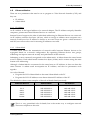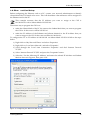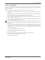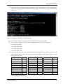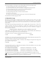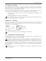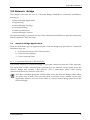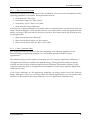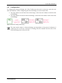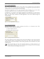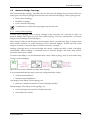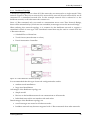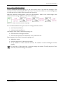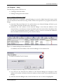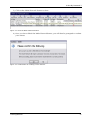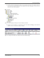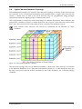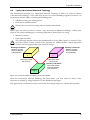
1
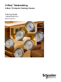
C-Bus™ Networking C-Bus™ Products Training Course Training Guide 1250SM0905R10/09 Retain for future use. C-Bus™ Networking C-Bus Products Training Course 1250SM0905R10/09 10/2009 HAZARD CATEGORIES AND SPECIAL SYMBOLS Read these instructions carefully and look at the equipment to become familiar with the device before trying to install, operate, service, or maintain it. The following special messages may appear throughout this bulletin or on the equipment to warn of potential hazards or to call attention to information that clarifies or simplifies a procedure. The addition of either symbol to a “Danger” or “Warning” safety label indicates that an electrical hazard exists which will result in personal injury if the instructions are not followed. This is the safety alert symbol. It is used to alert you to potential personal injury hazards. Obey all safety messages that follow this symbol to avoid possible injury or death. Danger indicates an immediately hazardous situation which, if not avoided, will result in death or serious injury. Warning indicates a potentially hazardous situation which, if not avoided, can result in death or serious injury. Caution indicates a potentially hazardous situation which, if not avoided, can result in minor or moderate injury. Caution, used without the safety alert symbol, indicates a potentially hazardous situation which, if not avoided, can result in property damage or improper operation. NOTE: Provides additional information to clarify or simplify a procedure. © 2009 Schneider Electric. All Rights Reserved. 1250SM0905R10/09 10/2009 C-Bus™ Networking C-Bus Products Training Course PLEASE NOTE Electrical equipment should be installed, operated, serviced, and maintained only by qualified personnel. This document is not intended as an instruction manual for untrained persons. No responsibility is assumed by Square D for any consequences arising out of the use of this manual. CLASS B FCC STATEMENT This equipment has been tested and found to comply with the limits for a Class B digital device, pursuant to Part 15 of the FCC Rules. These limits are designed to provide reasonable protection against harmful interference in a residential installation. This equipment generates, uses, and can radiate radio frequency energy and, if not installed and used in accordance with the instructions, may cause harmful interference to radio communications. However, there is no guarantee that interference will not occur in a particular installation. If this equipment does cause harmful interference to radio or television reception, which can be determined by turning the equipment off and on, the user is encouraged to try to correct the interference by one or more of the following measures: Reorient or relocate the receiving antenna. Increase the separation between the equipment and receiver. Connect the equipment into an outlet on a circuit different from that to which the receiver is connected. Consult the dealer or an experienced radio/TV technician for help. © 2009 Schneider Electric. All Rights Reserved. C-Bus™ Networking C-Bus Products Training Course 1250SM0905R10/09 10/2009 SAFETY PRECAUTIONS Carefully read and follow the safety precautions below before attempting to install or maintain electrical equipment. HAZARD OF ELECTRIC SHOCK, EXPLOSION, OR ARC FLASH Apply appropriate personal protective equipment (PPE) and follow safe electrical work practices. See NFPA 70E. This equipment must be installed and serviced by qualified electrical personnel. Turn off all electrical power supplying this equipment before working on or inside the equipment. Always use a properly rated voltage sensing device to confirm that power is off. Replace all devices, doors, and covers before turning on power to this equipment. Failure to follow these instructions will result in death or serious injury. © 2009 Schneider Electric. All Rights Reserved. © Copyri ght Cli psal Inte grated S ystems Pty Ltd 2 006. All ri ghts Reserve d. Thi s materi al i s copyri ght under Au stralian a nd in ternational la ws. Exc ept a s p ermitted un der t he re levant la w, n o p art o f t his work may be reproduced by any process wi thout prior written permission of and acknowledgement t o Clipsal Integrated Systems Pty Ltd. Clipsal and C-Bus are registered trademarks of Clipsal Australia Pty Ltd. The information in this manual is provided in good faith. Whilst Clipsal Integrated Systems (CIS) has endeavoured to ensure the relevance and accuracy of the information, it assumes no responsibility for any loss incurred as a result of its use. CIS does not warrant that the information is fit for any particular purpose, nor does it endorse its use in applications which are critical to the health or life of any human being. CIS reserves the right to update the information at any time without notice. V1.0 Sept 2006 Contents Scope Learning Outcomes 1.0 2.0 3.0 C-Bus Network Interface 1.1 Wiring 1.2 LED Indicators 1.3 Ethernet Basics 1.4 Ethernet Card Setup 1.5 CNI Configuration 1.6 Bandwidth Usage 1.7 Command Routing 1.8 Network Extending 1.9 C-Bus Network Interface Location Network Bridge 2.1 Network Bridge Applications 2.2 Configuration 2.3 Network Bridge Topology 2.4 Programming 2.5 Command Routing 2.6 Group Addressing 2.7 Traffic Considerations 2.8 Network Bridge Location C-Bus Network Topologies 3.1 Typical C-Bus Backbone Topology 3.2 Typical Ethernet Backbone Topology 3.3 Typical Vertical Network Topology 3.4 Typical Horizontal Network Topology 3.5 Network Topology Comparisons 5 5 6 7 8 9 10 11 13 14 14 14 15 15 17 19 22 29 31 33 33 34 35 36 37 38 39 C-Bus By Demand 3 Scope This manual aims to provide the trainee with the basic skills needed to design and commission a commercial C‐Bus installation. A fundamental technical background is required. The manual includes: • C‐Bus Network Design Concepts • Network Bridges • C‐Bus Network Interface In an ideal preparation for attending a C‐Bus Networks training course, it is recommended that the candidate has successfully completed the: • C‐Bus Basics Learning Outcomes By the end of this module, you should have an understanding of: • C‐Bus network construction • Network Bridge operation and programming • C‐Bus Network Interface operation and programming. Training Manual 5 C-Bus By Demand 3 1.0 C-Bus Network Interface This chapter will explain the programming and operation of a C‐Bus Network Interface (CNI), focusing on: • Wiring • LED Indicators • Ethernet Basics • Ethernet Card Setup • CNI Programming • Bandwidth Usage • Command Routing • Network Extending • C‐Bus Network Interface Location. It must be stressed that CIS does not support diagnostics and analysis of Ethernet networks. Training Manual 6 C-Bus By Demand 3 1.1 Wiring There are three fundamental wiring connections shown in Figure 1, which must be made to ensure the correct operation of the C‐Bus Network Interface: 1) C‐Bus Connection 2) 12 Volt Plug Adaptor 3) Ethernet Connection. Figure 1: Three wiring connections to a CNI. 1.1.1 C‐Bus Connection The C‐Bus power connection is used so the C‐Bus Network Interface can transmit and receive C‐Bus messages onto the network. On the front of the C‐Bus Network Interface there is a LED labelled ‘C‐Bus.’ This LED will illuminate orange if the C‐Bus is connected, and red if there is a problem with C‐Bus (no C‐Bus Clock or Voltage) or C‐Bus Connection. 1.1.2 12 Volt Connection The 12 Volt plug pack connects to the two screw down terminals on the top left of the C‐Bus Network Interface. The 12 Volt connector is not polarity sensitive, and will accept both AC and DC voltages. The 12 V connector is used to power the Ethernet to RS‐232 module, which is found inside of the unit. The 12 V plug pack is not designed to provide power to multiple C‐Bus Network Interfaces, so ensure that each unit has its own dedicated plug pack. 1.1.3 Ethernet Connection The Ethernet connection is used to connect the C‐Bus Network Interface to the Ethernet network. On the front of the C‐Bus Network Interface there is a LED labelled ‘Ethernet.’ This LED will illuminate orange if the connection to Ethernet is successful. If there is a problem with the Ethernet connection the LED will illuminate red. Training Manual 7 C-Bus By Demand 3 1.2 LED Indicators There are two LED Indicators on the CNI: 1) the Ethernet LED. 2) the C‐Bus LED. These indicators identify what the state of the Ethernet or C‐Bus is, by using various colours and flashing sequences. 1.2.1 Ethernet LED The Ethernet LED has multiple states indicating different conditions for the Ethernet part of the network, they are: Ethernet LED Condition Meaning Red Bad Ethernet Link. Red Flash (5 times) No DHCP Server found and a bad Ethernet Link. Orange Good Ethernet Link. Orange and Green Flashing Good Ethernet Link and an active session. Table 1: Ethernet LED conditions. 1.2.2 C‐Bus LED The C‐Bus LED also has multiple states indicating different conditions for the C‐Bus part of the network, they are: C-Bus LED Condition Red No Meaning C-Bus Connection. Red Flashing No C-Bus Connection, active comms to Ethernet side. Red / Orange Flash C-Bus clock present, C-Bus voltage marginal. Orange C-Bus clock present, C-Bus voltage good. Orange / Green Flash C-Bus clock present, C-Bus voltage good, active comms to Ethernet side. Table 2: C-Bus LED conditions. Training Manual 8 C-Bus By Demand 3 1.3 Ethernet Basics There are two parameters that need to set to program a C‐Bus Network Interface (CNI), and they are: • IP Address • Subnet Mask 1.3.1 IP Address An IP Address is the logical address of a network adapter. The IP Address uniquely identifies computers, printers and other Ethernet Devices on a network. Internet Protocol supports the idea of individual addressing for Ethernet Devices on a network. An IP Address contains four bytes (32 bits), which is enough to address most computers on a network. Each byte of an IP address is known as an octet. Octets are given a value between 0 and 255, but various rules exist for ensuring IP addresses are valid. 1.3.2 Subnet Mask A Subnet Mask allows the transmission of network traffic between Ethernet devices to be segregated based on a network configuration. By organising Ethernet devices into groups, subnetting can improve network security and performance of the network. Subnetting is more commonly recognised as the subnet mask. A Subnet shares the same format as an IP address. Each subnet mask contains four bytes (32 bits) and is written using the same format as IP Addressing. Although a Subnet Mask is constructed in the same form as a IP Address, it does not share the same function. A subnet mask accompanies an IP Address, and the two parameters work together. As a rule of thumb: • Program the CNI’s Subnet Mask to the same Subnet Mask as the PC • Program the CNI’s IP Address to an almost identical IP Address of the PC. The table below shows some examples of the rule of thumb listed previously. Ethernet Device Subnet Mask IP Address PC 1 255.255.255.0 192.168.170.1 PC 2 255.255.255.0 192.168.170.2 CNI 1 255.255.255.0 192.168.170.3 CNI 2 255.255.255.0 192.168.170.4 CNI 3 255.255.255.0 192.168.170.5 Printer 255.255.255.0 192.168.170.6 Table 3: IP Addressing Examples. This is a very generalised rule of thumb, but is the easiest way to configure network. There are exceptions to this rule. Training Manual 9 C-Bus By Demand 3 1.4 Ether net Card Setup Before configuring the Ethernet card on a PC, contact your network administrator to identify what address the CNI needs to be set to. This will determine what addresses will be assigned to the Ethernet card in the PC. This example assumes that the IP Address you want to assign to the CNI is 10.120.120.121 with a Subnet Mask of 255.255.0.0. The easiest way to program the CNI is to: • make the Subnet Mask of the PC the same as the Subnet Mask that you want to program the CNI to. In this case is will be 255.255.0.0. • make the IP Address of the Ethernet card almost identical to the IP Address that you want to assign to the CNI. In this case it will be 10.120.120.121. To configure the PC to IP Address 10.120.120.121 on Subnet Mask 255.255.0.0 follow the steps below: 1) Right click on ‘My Network Places’ and select ‘Properties’ 2) Right click on ‘Local Area Network’ and select ‘Properties’ 3) Scroll through the ‘Local Area Connection Properties’ and find ‘Internet Protocol TCP/IP.’ 4) Select ‘Internet Protocol TCP/IP’ and press the ‘Properties’ button. 5) Select the ‘Use the following IP Address’ and enter the selected IP Address and Subnet Mask as shown in Figure 6, then press ‘OK.’ Figure 2: Configuring the Ethernet card of a PC. Training Manual 10 C-Bus By Demand 3 1.5 CNI Configuration ARP stands for Address Resolution Protocol. ARP functions are used to determine the hardware address of Ethernet devices on a network. ARP functions may be used to program the C‐Bus Network Interface. To begin to program a CNI using ARP functions, follow the steps listed below: 1) Ensure both the CNI LED indicators are orange. This indicates that the CNI is correctly wired. 2) Configure your PC to a similar IP Address and Subnet Mask to the one you will assign to the CNI. Ensure that no other Ethernet device is using this address. 3) Open a Windows Command Prompt by clicking on Start and then Run. Type in cmd into the run window and press enter. 4) Type in ipconfig and press enter. This displays the IP Address and Subnet Mask of the PC, to ensure changes have taken effect. 5) In the Windows Command Prompt, enter arp –s followed by the IP address you are assigning to the CNI. After The IP address enter the Ethernet address (which can be found on a sticker on the side of the CNI). The command should be constructed like the line below. Press enter. This example assumes that the IP Address you want to assign to the CNI is 10.120.120.120 with a Subnet Mask of 255.255.0.0. The CNI Ethernet address is 00‐20‐4A‐ 62‐5D‐C2. • arp –s 10.120.120.120 00‐20‐4A‐62‐5D‐C2 6) Type in the following command and press enter. • telnet 10.120.120.120 1 7) You get an error message saying that a connection could not be made. 8) Type in the following command and press enter. • telnet 10.120.120.120 9999 Training Manual 11 C-Bus By Demand 3 9) Press enter again within 5 seconds to continue, otherwise connection to the telnet session will be lost. If a successful connection has been made, you will see a screen similar to the one below. Figure 3: Successful connection to a telnet session. 10) You will see a menu. Type in 0 (Server Configuration) and press enter. 11) You will be prompted to enter in the IP Address parameter. To do this type in: • 10 then press enter • 120 then press enter • 120 then press enter • 120 then press enter. 12) Keep pressing enter until you see the parameter Netmask. This is where you define the subnet mask. Enter in the amount of bits corresponding to the Subnet Mask you are using and Press enter. Subnet Mask Bits Subnet Mask Bits 255.255.255.252 2 255.255.252.0 10 255.252.0.0 18 255.255.255.248 3 255.255.248.0 11 255.248.0.0 19 255.255.255.240 4 255.255.240.0 12 255.240.0.0 20 255.255.255.224 5 255.255.224.0 13 255.224.0.0 21 255.255.255.192 6 255.255.192.0 14 255.192.0.0 22 255.255.255.128 7 255.255.128.0 15 255.128.0.0 23 255.255.255.0 8 255.255.0.0 16 255.255.254.0 9 255.254.0.0 17 Subnet Mask Bits 255.0.0.0 24 Table 4: Bits Per Subnet Mask Training Manual 12 C-Bus By Demand 3 So for this example you will type in 16 (for Subnet Mask 255.255.0.0) and press enter. 13) Keep pressing enter until you get to the main menu. 14) Once at the main menu, select 1 (Channel 1 Configuration) and press enter. 15) Keep pressing enter until you reach the Port Number parameter. 16) Type in the Port Number 10001 and press enter. 17) Keep pressing enter until you return to the main menu. 18) Press 9 to save and exit. 19) Whilst in the command prompt, type in ping 10.120.120.120 and press enter. You should now be able to ping your CNI. 1.6 Bandwidth Usage The amount of bandwidth on an Ethernet network that would be used by a CNI is very small. The CNI protocol is similar to a telnet protocol. Every single character sent to a CNI is placed into its own Ethernet packet and sent off. This means there is lots of overhead (about 50 bytes for every packet). This means that the Ethernet bandwidth used is roughly about 50 times that of C‐Bus. The C‐Bus PC Interface will send out characters at a baud rate of 9600 bits per second or 960 characters per second. This will create about 960 packets per second on Ethernet, at roughly 50 bytes per packet. Therefore: ‐ (50 bytes per packet) * (960 packets per second) = 48,000 bytes per second. C‐Bus itself is only 4000 bits per second, which equates to approximately 400 characters per second. The rate through the PCI won’t exceed this by much. On Ethernet, we have 3 common standards measured in bits per second: • 10Mb • 100 Mb • 1000 Mb On Ethernet you cannot get the quoted rates because of the collision detection system used. The maximum utilisation is about 20% of the theoretical speed. Converting to bytes (assuming 10 bits / character), and scaling by the typical max usage, this gives capacities respectively of: ‐ • 200 kBps • 2 MBps • 20 MBps So the bandwidth used for a C‐Bus Network Interface (CNI) in the absolute worst case where everything is going full speed will be: ‐ For a 10 Mb network bandwidth 48,000 (bytes) / 200,000 (bytes) * 100 = 24% For a 100 Mb network bandwidth 48,000 (bytes) / 2,000,000 (bytes) * 100 = 2.4% For a 1000 Mb network bandwidth 48,000 (bytes) / 20,000,000 (bytes) * 100 = 0.24% If using more than one CNI, the figures above need to be multiplied by the number of CNI’s. This is not a sustained bandwidth. It is assumed that it is a worst case burst on an already congested Ethernet network. In practice it will be less than this. Training Manual 13 C-Bus By Demand 3 1.7 Command Routing When using an Ethernet backbone in a multiple network C‐Bus installation, it is important to understand that CNI’s do not support tunnelling. Tunnelling is when a command is sent from one CNI to another, through the Ethernet network. This means that if an installation used 5 CNI’s (one on each floor), there would be no direct way to route messages between networks. However, interconnectivity can be provided by: • running a network bridge between the networks (remembering the limitations of the network bridge). • mapping group addresses via logic in Schedule Plus. If the installation requires network interconnectivity then using a CNI backbone may not be the most appropriate network topology. 1.8 Network Extending Times may occur when a network using a CNI reaches the limit of one of the C‐Bus operating parameters. If this occurs, a network bridge can be used to extend the network just as though a if a PC Interface is used (see Figure 8). Figure 4: Extending a network with a CNI. This is exactly the same as network extending for a PC Interface. 1.9 C-Bus Network Interface Location When installing a CNI into a commercial installation, common practice is to install them near a distribution board on the network it is controlling. Under no circumstances should a CNI be installed into a distribution board. Wiring regulations specify that Ethernet should never be wired into an enclosure with mains. If it is possible (depending on the installation) install all CNI’s into a central location, this could be in the basement of a building or a riser. Having all or multiple CNI’s in one location will allow the installation to be easily upgraded in the future, as well as simplifying the maintenance of the networks. This location may not suit every application, and is purely a suggestion to future proof the installation. Training Manual 14 C-Bus By Demand 3 2.0 Network Bridge This chapter will cover the use of a Network Bridge (5500NB) in commercial installations, focusing on: • Network Bridge Applications • Programming • Network Bridge Topology • Command Routing • Traffic Considerations • Network Bridge Locations The Network Bridge is primarily used in C‐Bus commercial installations to provide connectivity between different C‐Bus Networks. 2.1 Network Bridge Applications There are three main types of applications that a network bridge may provide in a commercial installation, they are: 1. Connectivity between CNI C‐Bus networks. 2. C‐Bus network extender. 3. C‐Bus Command Filter. 2.1.1 Connectivity Between C‐Bus Networks The primary function of a Network Bridge is to provide connectivity between C‐Bus networks. This means that a C‐Bus command that is generated on one network will be routed across the Network Bridge onto another C‐Bus network. This is particularly useful when routing commands between two networks with CNI’s. All C‐Bus commands generated will be routed across the Network Bridge (unless filters are used). Only if both C‐Bus networks share a common Group Address on the same Application Address, will you see the effect of a Group Address being routed across the Network Bridge. Training Manual 15 C-Bus By Demand 3 2.1.2 C‐Bus Network Extender There may be instances in a commercial C‐Bus installation, where one of the fundamental C‐Bus operating parameters is exceeded. These parameters may be: • more than 100 C‐Bus units • more than 2 Amps of C‐Bus Current • more than 1 km of C‐Bus CAT 5 cable • more then 255 Group Addresses. It is when one of these parameters is exceeded, that you will still need to extend the network. By using a Network Bridge to create another network, you will be able to create the appearance that there is one large C‐Bus network for the area in question. This means that to the average person, it will appear that: • there is more than 100 C‐Bus units • there is more than 2 Amps of C‐Bus current • there is more than 1 km’s of C‐Bus CAT 5 Cable. 2.1.3 C‐Bus Command Filter One of the lesser‐known features of the Network Bridge is the filtering capability. In the Network Bridge programming interface, you will find the parameter called ‘Connect Applications.’ This parameter gives you the options of selecting one of two unique Application Addresses or All Application Addresses (which is the default setting). The Application Addresses that are selected, are allowed to be routed through the Network Bridge. The benefit of filtering C‐Bus commands presents itself, on multiple network installations, where many different Application Addresses are used. If all Group Addresses on all Application Addresses are being routed across the Network Bridge, then there will be a lot of C‐Bus traffic. By filtering Applications you can minimise the amount of C‐Bus traffic to the Group Addresses on 1 or 2 Application Addresses only. Training Manual 16 C-Bus By Demand 3 2.2 Configuration To configure the Network Bridge, the C‐Bus Toolkit must be used to create new networks and edit unit addresses. When configuring the Network Bridge you must ensure that: • The Unit Address on the Near Side of the bridge, is the Network Address on the Far Side of the Bridge. • The Unit Address on the Far Side of the bridge, is the Network Address on the Near Side of the Bridge. Figure 5: Network Bridge Addressing. The near and far side of a Network Bridge are dependant on the point of reference of where the PCI or CNI are connected. So looking from the interface the first side of the Network Bridge seen is the near side. Training Manual 17 C-Bus By Demand 3 2.2.1 Connect Applications The Connect Applications parameters can be found on the Connection tab of the Network Bridge Graphical User Interface (GUI). The Application 1 and Application 2 parameters filter the commands that are routed through the Network Bridge. By default all applications are set to pass through the Network Bridge. If you wish to filter messages by application, then you will be limited to a maximum of 2 applications. If Application 1 was changed to the Lighting Application, and Application 2 was left at None, then only Group Addresses on the Lighting Application will be routed though the Network Bridge. All other Group Addresses on other applications will not be routed through the Network Bridge. Figure 6: Connect Applications Parameters. 2.2.2 Message Destination Message Destination has two unique parameters that allow us to determine what C‐Bus Network the Group Addresses will route to. 1) Send to adjacent network 2) Send to other remote network. Figure 7: Message Destination Parameters. The ‘Send to adjacent network’ parameter allows the Network Bridge to route locally generated C‐Bus commands directly to the adjoining C‐Bus network. The ‘Sent to other remote network’ parameter allows the network bridge to route locally generated C‐Bus commands to any other C‐Bus networks. Each network bridge can only send commands directly to 2 C‐Bus networks. If you require further connectivity, then you will either need to redesign the network topology, or add another Network Bridge to the network. Training Manual 18 C-Bus By Demand 3 2.3 Network Bridge Topology The network bridge topology, describes the way that network bridges are connected. There are three types of network topologies that may be used with network bridges. These topologies are: • Daisy Chain Topology • Backbone Topology • Fully Connected Topology. A combination of these three topologies may also be used. 2.3.1 Daisy Chain Topology A daisy chain topology refers to when multiple C‐Bus networks are connected in series via network bridges (see Figure 12). The daisy chain topology will only communicate 7 networks deep in series (utilising network bridges). When using Toolkit to scan though network bridges, there is a small time delay to retrieve data from remote networks. So when scanning across 6 network bridges, Toolkit will take much longer to scan the 7th network, than it would to scan the 1st network. Sending a message across a network bridge also causes a small time delay, which is generally unnoticeable. When sending a command across 6 network bridges, the delay time will be increased, and may be visible. To reduce time delays, it is recommended that a daisy chain topology only be 4 networks deep (using 3 network bridges). Figure 8: Three C-Bus networks in a daisy chain topology. It is recommended that this type of network configuration be used in: • small sized installations • medium sized installations. Advantages of the Daisy Chain topology are: • there are a minimum number of network bridges needed. Disadvantages of the Daisy Chain topology are: • not all messages are routed to all other networks • more difficult to model. Training Manual 19 C-Bus By Demand 3 2.3.2 Backbone Topology A backbone topology refers to when all C‐Bus networks are connected to a single central C‐Bus network. Figure 13 shows how network 253, network 252, network 251 and network 250, are all connected to a centralised network 254. In this example network 254 is referred to as the backbone network, as all other networks connect to it. Since a C‐Bus command only ever needs to communicate across one C‐Bus Network Bridge, there will be minimal delays (which are not noticeable) in messages across the network bridge. When utilizing this network topology, it is common for the backbone network to support a centralised control of some type. The centralised control that may be used to control all of the C‐Bus networks are: • Schedule Plus or HomeGate • Touch Screen (monochrome or colour) • Pascal Automation Controller. Figure 9: C-Bus backbone network topology. It is recommended that this type of network configuration be used in: • medium sized installations • large sized installations. Advantages of the Backbone topology are: • Simple model • Devices on the backbone network can communicate to all networks • Individual network do not interfere with each other. Disadvantages of the Backbone topology are: • not all messages are routed to all other networks • backbone network may become congested with C‐Bus commands from other networks. Training Manual 20 C-Bus By Demand 3 2.3.3 Fully Connected Topology A fully connected network topology is the most rarely used of all network topologies. The concept of a fully connected network is that each C‐Bus network will have a network bridge that is connected to every other C‐Bus network (see Figure 14). With this particular configuration it may also be feasible to remove one of the bridges, and utilise the dual routing capability of the network bridges. Figure 10: A fully connected network topology. It is recommended that this type of network configuration be used in: • small sized installations • medium sized installations. Advantages of the Fully Connected topology are: • network acts as one large network • each network will send a command to every other network. Disadvantages of the Fully Connected topology are: • difficult to set up • increased amount of C‐Bus network traffic • as the number of C‐Bus networks increase, the number of network bridges increase rapidly. To fully map 3 C‐Bus networks, 3 network bridges are needed. To fully map four C‐Bus networks, 6 network bridges are needed. Training Manual 21 C-Bus By Demand 3 2.4 Program ming The following sections will focus on: • Creating a Network Online • Editing Existing Networks Online 2.4.1 Creating A Network Online The most simple way to program a network bridge is to use the ‘Make Networks’ button while you are connected to the network using Toolkit. Follow the steps below to program the network bridge. 1) Scan the C‐Bus Local Network. You will see that a new Network Bridge will show up at Unit Address 255 (like all other new C‐Bus units). 2) Readdress the Unit Address of the Network Bridge to the Network Address of the network that you are about to create. By default each local network has the address 254, so the next recommended Network Address is 253 (it is best to use network addresses that work backwards from 254. Eg. 253, 252, 251, 250 etc). Figure 11: A Network Bridge at Unit Address 255. So readdress the Unit Address of the Network Bridge to Unit Address 253. Figure 12: Readdress Network Bridge from Unit Address 255 to 253. 3) You will now see that the Unit Address of the Network Bridge has changed to Unit Address 253 (which will be the Network Address of the far side of the selected Network Bridge). 4) Select the Network Bridge in the ‘Units On Network’ view so that is it highlighted. Training Manual 22 C-Bus By Demand 3 5) Click on the ‘Make Network’ button as show. Figure 13: Click the Make Network button. 6) Once you have clicked the Make Network button, you will then be prompted to confirm your actions. Figure 14: Confirmation of creating a new network. Training Manual 23 C-Bus By Demand 3 7) Toolkit will that automatically create a new network and scan in the remote network. You will then see that Toolkit has also updated the Project Manager to show the new network in your selected project. Figure 15: Project Manager showing the Local and Remote networks. 8) Change the Unit Address on the Remote side of the Network Bridge to the Network Address of the Local Network (254 by default). Figure 16: Change Unit Address of the Remote side of the Network Bridge. Training Manual 24 C-Bus By Demand 3 2.4.2 Editing Existing Networks Online To identify the true setting of how a Network Bridge is programmed it is best to look at its true addressing. This can be done by simply selecting the project in the Project Manager. Figure 17: True Network Addressing. You will see the highlighted section that states 254/p/253. This means that network 253 (the selected network) is physically linked through network 254. To Readdress a network, you must: 1) Navigate to the Project Manager and select the network you wish to edit. 2) On the toolbar you will find a button labelled Readdress. Figure 18: Readdress Button. Training Manual 25 C-Bus By Demand 3 3) Once you have clicked the Readdress button you will then be prompted to select a new Network Address for the selected network. Figure 19: Selecting a new Network Address. 4) Once you have clicked ok, you will then be prompted to readdress the corresponding Unit Address to match the new Network Address. Click Yes. Figure 20: Automatic Readdressing of Unit Addresses. 5) You will now see that the Unit Address which corresponds to the Network Address (that was just changed) has automatically been updated. Figure 21: Unit Address of the Network Bridge automatically updated. Training Manual 26 C-Bus By Demand 3 2.4.3 Creating Networks Offline To create a network offline, which contains multiple bridges, please follow the steps below. 1) Create a new C‐Bus project and add a network (using a Serial PCI at COM1 if possible). 2) Once you have done this, select the project in the Project Manager and click on the Add Networks button on the toolbar. Figure 22: The Add Network button. 3) Specify the Network Name. 4) Specify the Network Type (in this case Bridge – Wired). 5) Specify the Transit Network (the previous network that the bridge is connected to). 6) Check the Add Bridge tick box to add the bridge to the database of both networks. 7) Select Bridge Type for the part number (in this case 5500NB), and press ok. Figure 23: Adding network and transit details. Training Manual 27 C-Bus By Demand 3 8) Enter any Serial Numbers if applicable otherwise press the OK button. Figure 24: Adding Serial Numbers. Your network has now been created with a bridge. The databases of both networks now will have a network bridges in the databases and the unit addresses will be configured in accordance with default network addressing. If you click on the Topology branch of your project (in the Project Manager), you will see the a visual display of the network topology. Figure 25: Network Topology Training Manual 28 C-Bus By Demand 3 2.5 Command Routing Command routing is a very important consideration to contemplate when designing a multiple network C‐Bus installation. Every single C‐Bus command has information in it, that specifies which network to communicate with. When routing C‐Bus commands, it is important to understand two things: 1) If a C‐Bus command is generated specifically for a dedicated network, then the dedicated network is the only C‐Bus network that will see and react to the command sent. Eg. A selected Group Address from a Touch Screen. 2) Messages containing no routing information are destined only for the network that the command was generated on. For C‐Bus commands with no routing information to be routed to another network, a network bridge must be used. Standard C‐Bus input units are not capable of directly routing C‐Bus messages to other networks. There are a number of devices that will actually route C‐Bus commands across network bridges. These devices are: • Network Bridges • Other routing enabled devices. 2.5.1 Bridge Routing On C‐Bus networks where there are no devices capable of routing C‐Bus commands to another C‐Bus network, a network bridge can be used to route the commands. This will allow commands with no routing information to be transmitted to: • the adjacent C‐Bus network • one other C‐Bus network in the installation. Training Manual 29 C-Bus By Demand 3 2.5.2 Other Routing Enabled Devices C‐Bus has a range of products and software packages that are capable of routing commands directly to other C‐Bus networks. The routing enabled devices are products such as: • Schedule Plus & HomeGate • Touch Screens (Monochrome and Colour) • Pascal Automation Controller (PAC). When programming with any of these other routing enabled devices, the commissioning software allows the specification of what network to send the command directly to. This means that the command will be routed to the specified network directly, and will appear like it was generated on that network. Figures 30 & 31 show this. Figure 26: Send a command to the local network. Figure 27: Sends a command directly to a remote network. Training Manual 30 C-Bus By Demand 3 2.6 Group Addressing When creating new networks, it is very important to manage the group addresses that are being used on all other networks. This will ensure that you do not use two identical group addresses to control different outputs. An example of this is that you may have a relay on the local network, and a dimmer on the remote network. Both of these units are using the Lighting Application (56 or 38h), and Group Address 01. The problem is that on the Local Network, Group Address 01 might control the Kitchen Lights, where Group Address 01 on the Remote Network may control the Bedroom Lights. To avoid this it is recommended that each time you create a new C‐Bus network, you copy the Tags you have already created to the new network. This way you can ensure that there is no duplication of common group addresses across networks. To duplicate the already made group addresses, follow the steps below. 1) Navigate to the Project Manager and select the new network that you have just created. Figure 28: Selecting the newly created network. Training Manual 31 C-Bus By Demand 3 2) On the toolbar, select the Copy Tags button. Figure 29: The Copy Tags button. 3) You will then be prompted with a dialogue box that asks you which network would you like to copy the tags from. Select the relevant network and press ok. Figure 30: Selecting a network to copy tags from. 4) Now all of your tags will show up on the new network. Training Manual 32 C-Bus By Demand 3 2.7 Traffic Considerations When designing a multiple network project using network bridges, it is extremely important to consider the amount of C‐Bus traffic being sent around the networks. 2.7.1 Daisy Chain Considerations When using a daisy chain configuration, network traffic is not usually much of a problem. This is due to the network bridged only being able to send commands to two networks. What must be considered it the speed of the networks. Reducing the amount of networks in the daisy chain can increase the speed of the network. 2.7.2 Backbone Considerations When using a C‐Bus backbone configuration, network traffic on the C‐Bus backbone must be taken into consideration. This is due to a number of networks routing all of their messages back to the backbone network, so a user interface can control and monitor the networks. Where possible it may be an option to use the Connect Application option to filter unwanted applications from communicating to the backbone network. 2.8 Network Bridge Location When installing network bridges into a commercial installation, common practise is to install them into a distribution board on the remote network it is controlling. If it is possible (depending on the instillation) it may be worth installing all network bridges into a central location, this could be in the basement of a building or a riser. Having all the network bridges in one location will allow the installation to be easily upgraded in the future. Network Bridges may be swapped over easily with C‐Bus Network Interfaces (CNI’s). By having the bridges centralised, rewiring to convert the network bridges to CNI’s will be significantly reduced. This location may not suit every application, and is purely a suggestion to future proof the installation. Training Manual 33 C-Bus By Demand 3 3.0 C-Bus Network Topologies This chapter will explain some of the more commonly used C‐Bus Network Topologies, focusing on: • Typical C‐Bus Backbone Topologies • Typical Ethernet Backbone Topologies • Typical Vertical Network Topologies • Typical Horizontal Network Topologies A C‐Bus Network Topology is a way of explaining the physical layout of multiple C‐Bus Networks. When designing C‐Bus Network Topologies, there are different topologies that may be used (in various configurations), to connect to other C‐Bus networks. Training Manual 34 C-Bus By Demand 3 3.1 Typical C-Bus Backbone Topology A C‐Bus backbone topology is a commonly used network topology in C‐Bus projects. Utilising the C‐Bus Network Bridge (5500NB), the connectivity between C‐Bus networks is provided by a dedicated C‐Bus network operating as backbone. Using network bridges will allow this topology to transmit locally generated C‐Bus commands between adjacent and remote C‐Bus networks. Figure 31: C-Bus Backbone Topology A C‐Bus Touch Screen or End User Software package is commonly placed onto the C‐Bus backbone, to control and monitor all of the C‐Bus networks in commercial installations. This network topology is commonly used in multi‐story buildings. Training Manual 35 C-Bus By Demand 3 3.2 Typical Ethernet Backbone Topology An Ethernet backbone is another of the more commonly used C‐Bus network topologies. Utilising C‐Bus Ethernet Interfaces (5500CN), the connectivity between C‐Bus networks is provided by an Ethernet Switch or Hub. Figure 32: Ethernet Backbone Topology The C‐Bus Network Interfaces do not support network tunnelling. This means that you cannot communicate directly between networks. A centralised PC on the Ethernet network may be used to send and receive commands from all C‐Bus networks. This network topology is commonly used in multi‐story buildings, utilising the existing Ethernet backbone. Training Manual 36 C-Bus By Demand 3 3.3 Typical Vertical Network Topology The fundamental principle of a Vertical C‐Bus Network Topology, is that the C‐Bus network will run vertically. So on a commercial installation with multiple levels, a single C‐Bus network will control a certain area of each level. Each network may be programmed using multiple Applications within the lighting range, to identify each level. This configuration is commonly used in the design of stadiums and arenas. Most stadiums and arenas have a number of levels. So rather than have one or more C‐Bus networks control each floor, one C‐Bus network will control each level of a section of the stadium or arena. Each vertical C‐Bus network will usually be connected via an Ethernet or C‐Bus backbone. Figure 33: C-Bus Vertical Network Topology This network topology may use an Ethernet backbone, where each C‐Bus network is connected to the Ethernet Backbone via a C‐Bus Network Interface (5500CN). A C‐Bus backbone may also be used, where each network will be connected to the C‐Bus backbone via a Network Bridge (5500NB). Training Manual 37 C-Bus By Demand 3 3.4 Typical Horizontal Network Topology The fundamental principle of a Horizontal Network Topology is when you want to connect C‐Bus between buildings. C‐Bus cable may be used to connect buildings together, however you must ensure that the cables connecting the buildings are: • Suitable for being run underground • Enclosed in suitable conduit. Please refer to your local wiring rules for further information. Fibre Optics can also be used to connect C‐Bus networks in different buildings. A fibre optic network will connect buildings by converting Ethernet to Fibre Optics, by using: • Media Converters • Fibre Optic Switches. The following diagram shows the fundamentals of using Fibre Optics to connect C‐Bus networks. Please contact a Fibre Optic specialist for further details. Clipsal Integrated Systems will not support fibre optic network design. Building 2 Hardware: - Media Converter - Ethernet Network - CNI (5500CN) Building 2 Building 3 Hardware: - Media Converter - Ethernet Network - CNI (5500CN) Building 3 Fibre Optic Cable Min 2 Cores Fibre Optic Cable Min 2 Cores Building 1 Hardware: - Fibre Optic Switch - Ethernet Network - CNI (5500CN) Building 1 Figure 34: Horizontal Network Topology using Fibre Optics. Once the connectivity between buildings has been made, you may create as many C‐Bus networks as needed, by using Ethernet or C‐Bus backbone topologies. This application is commonly used for university and collage campuses, schools and hospitals. Training Manual 38 C-Bus By Demand 3 3.5 Network Topology Comparisons The following sections will identify the: • Advantages Of A C‐Bus Backbone • Disadvantages Of A C‐Bus Backbone • Advantages Of A Ethernet Backbone • Disadvantages Of A Ethernet Backbone 3.5.1 Advantages Of A C‐Bus Backbone Some of the advantages of using a C‐Bus Backbone are: • The C‐Bus Backbone allows communications between networks, via Network Bridges. • There is no need for PC control, since PAC’s and Touch Screens can control and monitor networks across Network Bridges. • AC‐Bus Backbone allows the connection of 3rd party systems to the local network (via PCI or CNI). The Network Bridges will then route commands to remote networks. • A C‐Bus Backbone is a unique stand‐alone system, with no interference from other systems or Ethernet related issues. • A C‐Bus Backbone can run for 1km. A C‐Bus Backbone allows HomeGate or Schedule Plus to control and monitor all networks. 3.5.2 Disadvantages Of A C‐Bus Backbone Some of the disadvantages of using a C‐Bus Backbone are: • Poor programming may cause excessive traffic on the backbone network, which may cause problems. • A C‐Bus Backbone may have excessive synchronisation times when scanning multiple networks through a single PCI or CNI (via Toolkit, Schedule Plus or HomeGate). • A C‐Bus Backbone has a slower communications speed, when compared to an Ethernet backbone. Training Manual 39 C-Bus By Demand 3 3.5.3 Advantages Of A Ethernet Backbone Some of the advantages of using a C‐Bus Backbone are: • An Ethernet Backbone can utilise existing Ethernet Backbone infrastructure. • An Ethernet Backbone has a faster synchronisation time when scanning C‐Bus networks (via Toolkit, Schedule Plus or HomeGate). • An Ethernet Backbone allows HomeGate or Schedule Plus to control and monitor all networks. • An Ethernet Backbone allows C‐Bus networks to be spread out over a large area (via fibre optics). 3.5.4 Disadvantages Of A Ethernet Backbone Some of the advantages of using a C‐Bus Backbone are: • An Ethernet Backbone does not allow communications between C‐Bus networks. • Network Administrators may not allows CNI’s on the Ethernet Network, as a result a services network may need to be installed • Schedule Plus monitoring and control is reliant on a stable Ethernet Network. • Ethernet networks add an extra element of complexity and a possible source of problems. Training Manual 40 C-Bus™ Networking Training Guide SUPPORT AND TRAINING Contact the Customer Information Center for technical support by phone at 1-888-778-2733 or e-mail at [email protected]. You may also find helpful information on our web site at www.Schneider-Electric.us. Schneider Electric, USA 320 Tech Park Drive, Suite 100 La Vergne, TN, 37086 1-888-778-2733 www.schneider-electric.us Square D, , Clipsal, C-Bus, Saturn and Neo are trademarks or registered trademarks of Schneider Electric and/or its affiliates in the United States and/or other countries. Electrical equipment should be installed, operated, serviced, and maintained only by qualified personnel. No responsibility is assumed by Schneider Electric for any consequences arising out of the use of this material. © 2009 Schneider Electric. All Rights Reserved. 1250SM09052 10/2009