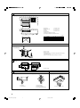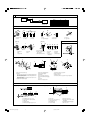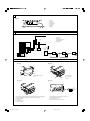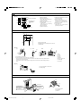
1
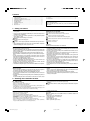
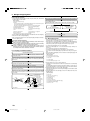
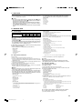
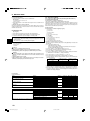
Air-Conditioners SEZ-KD25,KD35,KD50,KD60,KD71VA INSTALLATION MANUAL FOR INSTALLER For safe and correct use, please read this installation manual thoroughly before installing the air-conditioner unit. INSTALLATIONSHANDBUCH FÜR INSTALLATEURE Zum sicheren und ordnungsgemäßen Gebrauch der Klimaanlage das Installationshandbuch gründlich durchlesen. MANUEL D’INSTALLATION Italiano VOOR DE INSTALLATEUR Voor een veilig en juist gebruik moet u deze installatiehandleiding grondig doorlezen voordat u de airconditioner installeert. INSTALLATIONSMANUAL Español PER L’INSTALLATORE Per un uso sicuro e corretto, leggere attentamente questo manuale di installazione prima di installare il condizionatore d’aria. INSTALLATIEHANDLEIDING Français PARA EL INSTALADOR Para un uso seguro y correcto, lea detalladamente este manual de instalación antes de montar la unidad de aire acondicionado. MANUALE DI INSTALLAZIONE Deutsch POUR L’INSTALLATEUR Veuillez lire le manuel d’installation en entier avant d’installer ce climatiseur pour éviter tout accident et vous assurer d’une utilisation correcte. MANUAL DE INSTALACIÓN English Nederlands FÖR INSTALLATÖREN Läs denna installationsmanual noga för säkert och korrekt bruk innan luftkonditioneringen installeras. Svenska INSTALLATIONSMANUAL TIL INSTALLATØREN Læs venligst denne installationsmanual grundigt, før De installerer airconditionanlægget, af hensyn til sikker og korrekt anvendelse. MANUAL DE INSTALAÇÃO PARA O INSTALADOR Para segurança e utilização correctas, leia atentamente este manual de instalação antes de instalar a unidade de ar condicionado. E°XEIPI¢IO O¢H°IøN E°KATA™TA™H™ °π∞ ∞À∆√¡ ¶√À ∫∞¡∂π ∆∏¡ ∂°∫∞∆∞™∆∞™∏ °È· ·ÛÊ¿ÏÂÈ· Î·È ÛˆÛÙ‹ ¯Ú‹ÛË, ·Ú·Î·Ï›ÛÙ ‰È·‚¿ÛÂÙ ÚÔÛ¯ÙÈο ·˘Ùfi ÙÔ ÂÁ¯ÂÈÚ›‰ÈÔ ÂÁηٿÛÙ·Û˘ ÚÈÓ ·Ú¯›ÛÂÙ ÙËÓ ÂÁηٿÛÙ·ÛË Ù˘ ÌÔÓ¿‰·˜ ÎÏÈÌ·ÙÈÛÌÔ‡. РУКОВОДСТВО ПО УСТАНОВКЕ 1 ∂ÏÏËÓÈο Русский MONTÖR ‹Ç‹N Emniyetli ve do¤ru biçimde nas›l kullan›laca¤›n› ö¤renmek için lütfen klima cihaz›n› monte etmeden önce bu elkitab›n› dikkatle okuyunuz. KB79H132H01_cv.p65 Português ДЛЯ УСТАНОВИТЕЛЯ Для осторожного и правильного использования прибора необходимо тщательно ознакомиться с данным руководством по установке до выполнения установки кондиционера. MONTAJ ELK‹TABI Dansk 6/15/07, 3:48 PM Türkçe 3 3.1 [Fig. 3-1] 50~150 C B A C A 49 625 B 450 4 450 23 90 D 100 20 D 2 1 B A B C D E F G 200 3 F E A Access door 1 600 mm or more Electrical parts box 2 100 mm or more Air inlet 3 10 mm or more Air outlet 4 300 mm or more Ceiling surface Service space (viewed from the side) Service space (viewed from the direction of arrow) (mm) A B C D E 700 752 798 660 800 900 952 998 860 1000 1100 1152 1198 1060 1200 E 777 Model SEZ-KD25 SEZ-KD35, 50 SEZ-KD60, 71 G 3.3 [Fig. 3-2] C ■ SUZ-KA25VA A A A 100 mm or more B 350 mm or more C Basically open 100 mm or more without only obstruction in front and on both sides of the unit. D 200 mm or more (Open two sides of left, right, or rear side.) B D 4 [Fig. 4-1] L Z W X Y 5 A Center of gravity A 5.2 5.1 [Fig. 5-1] [Fig. 5-2] [Fig. 5-3] C D A B A D C E A Unit body B Lifting machine C Nuts (field supply) D Washers (accessory) E M10 hanging bolt (field supply) A Indoor unit’s bottom surface 2 KB79H132H01_illust.p65 2 6/15/07, 3:52 PM 6 6.1 [Fig. 6-1] øB a øA a Indoor unit b Outdoor unit B 6.35 6.35 6.35 9.52 A 9.52 12.7 15.88 15.88 Model SEZ-KD25, 35 SEZ-KD50 SEZ-KD60 SEZ-KD71 b 6.2 [Fig. 6-3] [Fig. 6-4] b a [Fig. 6-5] c d 90° e b a f a c b d a Copper tubes b Good c No good d Tilted a Burr b Copper tube/pipe e Uneven f Burred [Fig. 6-6] c Spare reamer d Pipe cutter a Flare nut b Copper tube 6.3 [Fig. 6-7] a b a A e e f g h b d b c [Fig. 6-8] d c c i a Flaring tool b Die c Copper tube a Smooth all around b Inside is shining without any scratches c Even length all around d Flare nut e Yoke d Too much e Tilted f Scratch on flared plane g Cracked h Uneven i Bad examples [Fig. 6-9] J H B A C E D N I M O L 20 F F J H E AG 20 O 20 L 20 N G L K A Pipe cover (small) (accessory) B Caution: Pull out the thermal insulation on the refrigerant piping at the site, insert the flare nut to flare the end, and replace the insulation in its original position. Take care to ensure that condensation does not form on exposed copper piping. C Liquid end of refrigerant piping D E F G H I J K L M N O Gas end of refrigerant piping Site refrigerant piping Main body Pipe cover (large) (accessory) Thermal insulation (field supply) Pull Flare nut Return to original position Ensure that there is no gap here Plate on main body Band (accessory) Ensure that there is no gap here. Place join upwards. 6.5 [Fig. 6-10] [Fig. 6-11] I B A A B C G F 1 C C E 5 25 D E H C D A B C D E 2 Downward slope 1/100 or more Connection dia. R1 external thread Indoor unit Collective piping Maximize this length to approx. 10 cm A B C D E Indoor unit Pipe cover (short) (accessory) Tie band (accessory) Band fixing part Insertion margin F Drain hose (accessory) G Drain pipe (O.D. ø32 PVC TUBE, field supply) H Insulating material (field supply) I Max.145 ± 5 mm 3 KB79H132H01_illust.p65 3 6/15/07, 3:52 PM 7 [Fig. 7-1] F A B C D E F G E D C B G Air inlet Air outlet Access door Ceiling surface Canvas duct Air filter Inlet grille A 8 8.1 [Fig. 8-1] A B C D E A S1 S2 S3 12 Indoor unit Outdoor unit Wired remote controller Main switch/fuse Grounding B S1 S2 S3 C D For Power supply A B E D A A C C C For Power supply 8.2 [Fig. 8-2-1] [Fig. 8-2-2] A B B A Screw holding cover (2pcs) B Cover [Fig. 8-2-3] A A Terminal bed box B Knockout hole C Remove C [Fig. 8-2-4] J E S2 S3 S3 S2 S1 2 H 1 S1 M K F G I E Use PG bushing to keep the weight of the cable and external force from being applied to the power supply terminal connector. Use a cable tie to secure the cable. F Power source wiring G Tensile force H Use ordinary bushing I Transmission wiring J K L M Terminal bed for power source and indoor transmission Terminal bed for remote controller To 1-phase power source Transmission line to the remote controller 4 KB79H132H01_illust.p65 4 6/15/07, 3:52 PM L 8 8.2 [Fig. 8-3] A Indoor terminal block 2 1 2 B Earth wire (green/yellow) 4 5 1 C Indoor/outdoor unit connecting wire 3-core 1.5 mm2 or more 6 3 L N D Outdoor terminal block 7 A Indoor terminal block B Earth wire (green/yellow) C Indoor/outdoor unit connecting wire 3core 1.5 mm2 or more 4 Always install an earth wire (1-core 1.5 mm2) longer than other cables 5 Remote controller cable Wire No × size (mm2) : Cable 2C × 0.3 D Outdoor terminal block E Power supply cord : 2.0 mm2 or more 1 Connecting cable Cable 3-core 1.5 mm2, in conformity with Design 245 IEC 57. 2 Indoor terminal block 3 Outdoor terminal block This wire accessory of remote controller (wire length : 10m, non-polar. Max. 500m) 6 Wired remote controller 7 Power supply cord Cable 3-core 2.0 mm2 or more, in conformity with Design 245 IEC 57. E Power supply cord : 2.0 mm2 or more 8.3 [Fig. 8-4] B 30 A 30 83.5 30 A Remote controller profile B Required clearances surrounding the remote controller C Installation pitch 120 C 46 [Fig. 8-5] A B D C B-1. B-2. H E F I H G I J I H C D E F G H I J A For installation in the switch box: B For direct installation on the wall select one of the following: • Prepare a hole through the wall to pass the remote controller cord (in order to run the remote controller cord from the back), then seal the hole with putty. • Run the remote controller cord through the cut-out upper case, then seal the cut-out notch with putty similarly as above. Wall Conduit Lock nut Bushing Switch box Remote controller cord Seal with putty Wood screw [Fig. 8-6] A A To the terminal block on the indoor unit B TB6 (No polarity) AB TB6 B 8.4 [Fig. 8-7] [Fig. 8-8] A C Service panel Be sure to fix the indoor/outdoor unit connecting wire using this cord clamp. Remove one fixing screw to open the service panel. B A Loosen terminal screw B Terminal block C Lead wire 5 KB79H132H01_illust.p65 5 6/15/07, 3:52 PM 8 8.5 [Fig. 8-9] 2 3 4 4 1 TEMP. F E G MENU BACK PAR-21MAA MONITOR/SET ON/OFF ON/OFF 1 A FILTER DAY CLOCK 2 CHECK TEST OPERATION B CLEAR 1 C D 9 1 ⁄ 2 ⁄ 3 ⁄ 4 ⁄ Mode number Setting number Refrigerant address Unit number A B C D E F G Filter button (<Enter> button) TEST button Set Time button Timer On/Off button (Set Day button) Mode selection button Set temperature button Timer Menu button (Monitor/Set button) 9.2 [Fig. 9-1] F E C 9.3 [Fig. 9-2] D B B ED TEST RUN COOL, HEAT ˚C ˚C ˚C SIMPLE ˚C SIMPLE TEMP. MENU ON/OFF ON/OFF A TEMP. C FILTER MENU BACK MONITOR/SET DAY CLOCK OPERATION MONITOR/SET A ON/OFF button B Test run display C Indoor temperature liquid line temperature display D ON/OFF lamp E Power display CLOCK OPERATION F Error code display Test run remaining time display G Set temperature button H Mode selection button I Fan speed button M TEST button [Fig. 10-1] A B C D CHECK button Refrigerant address TEMP. button IC: Indoor unit OC: Outdoor unit E Check code B E A C D F M G L K H I J A B C D E F G CLEAR A 10.1 Indoor unit Union Liquid pipe Gas pipe Stop valve Outdoor unit Refrigerant gas cylinder operating valve H Refrigerant gas cylinder for R410A with siphon I Refrigerant (liquid) J Electronic scale for refrigerant charging K Charge hose (for R410A) L Gauge manifold valve (for R410A) M Service port 6 6 CHECK TEST I M 10 KB79H132H01_illust.p65 FILTER DAY CLEAR PAR-21MAA HG ON/OFF CHECK TEST BACK PAR-21MAA ON/OFF 6/15/07, 3:52 PM Contents 1. 2. 3. 4. 5. 6. 7. 8. Safety precautions ................................................................................... 7 Selecting the installation location ............................................................. 7 Selecting an installation site & Accessories ............................................. 8 Fixing hanging bolts ................................................................................. 8 Installing the unit ...................................................................................... 8 Refrigerant piping work ............................................................................ 9 Duct work ............................................................................................... 11 Electrical work ........................................................................................ 11 9. Test run .................................................................................................. 13 10. Maintenance .......................................................................................... 14 This Installation Manual describes only for the indoor unit and the connected outdoor unit of SUZ series. If the connected outdoor unit is MXZ series, refer to the Installation Manual for MXZ series. 1. Safety precautions • Please report to or take consent by the supply authority before connection to the system. • Be sure to read “The following should always be observed for safety” before installing the air conditioner. • Be sure to observe the cautions specified here as they include important items related to safety. • The indications and meanings are as follows. Warning: Could lead to death, serious injury, etc. Caution: Could lead to serious injury in particular environments when operated incorrectly. • After reading this manual, be sure to keep it together with the instruction manual in a handy place on the customer’s site. Symbols put on the unit : Indicates an action that must be avoided. : Indicates that important instructions must be followed. : Indicates a part which must be grounded. : Indicates that caution should be taken with rotating parts. : Indicates that the main switch must be turned off before servicing. : Beware of electric shock. : Beware of hot surface. Warning: Carefully read the labels affixed to the main unit. Warning: • Do not install it by yourself (customer). Incomplete installation could cause injury due to fire, electric shock, the unit falling or leakage of water. Consult the dealer from whom you purchased the unit or special installer. • Install the unit securely in a place which can bear the weight of the unit. When installed in an insufficient strong place, the unit could fall causing injured. • Use the specified wires to connect the indoor and outdoor units securely and attach the wires firmly to the terminal board connecting sections so the stress of the wires is not applied to the sections. Incomplete connecting and fixing could cause fire. • Do not use intermediate connection of the power cord or the extension cord and do not connect many devices to one AC outlet. It could cause a fire or an electric shock due to defective contact, defective insulation, exceeding the permissible current, etc. • Check that the refrigerant gas does not leak after installation has completed. • Perform the installation securely referring to the installation manual. Incomplete installation could cause a personal injury due to fire, electric shock, the unit falling or leakage of water. • Perform electrical work according to the installation manual and be sure to use an exclusive circuit. If the capacity of the power circuit is insufficient or there is incomplete electrical work, it could result in a fire or an electric shock. • Attach the electrical part cover to the indoor unit and the service panel to the outdoor unit securely. If the electrical part cover in the indoor unit and/or the service panel in the outdoor unit are not attached securely, it could result in a fire or an electric shock due to dust, water, etc. • Be sure to use the part provided or specified parts for the installation work. The use of defective parts could cause an injury or leakage of water due to a fire, an electric shock, the unit falling, etc. • Ventilate the room if refrigerant leaks during operation. If the refrigerant comes in contact with a flame, poisonous gases will be released. Caution: • Perform grounding. Do not connect the ground wire to a gas pipe, water pipe arrester or telephone ground wire. Defective grounding could cause an electric shock. • Do not install the unit in a place where an inflammable gas leaks. If gas leaks and accumulates in the area surrounding the unit, it could cause an explosion. • Install a ground leakage breaker depending on the installation place (where it is humid). If a ground leakage breaker is not installed, it could cause an electric shock. • Perform the drainage/piping work securely according to the installation manual. If there is a defect in the drainage/piping work, water could drop from the unit and household goods could be wet and damaged. • Fasten a flare nut with a torque wrench as specified in this manual. When fastened too tight, a flare nut may broken after a long period and cause a leakage of refrigerant. 2. Selecting the installation location 2.1. Indoor unit • Where the air filter can be removed and replaced easily. • • • • Where airflow is not blocked. Where cool air spreads over the entire room. Where it is not exposed to direct sunshine. At a distance 1 m or more away from your TV and radio (to prevent picture from being distorted or noise from being generated). • In a place as far away as possible from fluorescent and incandescent lights (so the infrared remote control can operate the air conditioner normally). Warning: Mount the indoor unit into a ceiling strong enough to withstand the weight of the unit. 2.2. Outdoor unit • Install the unit horizontally. • • • • • Caution: Avoid the following places for installation where air conditioner trouble is liable to occur. • Where there is too much machine oil. • Salty environment as seaside areas. • Hot-spring areas. • Where sulfide gas exists. • Other special atmospheric areas. Where it is not exposed to strong wind. Where airflow is good and dustless. Where it is not exposed to rain and direct sunshine. Where neighbours are not annoyed by operation sound or hot air. Where rigid wall or support is available to prevent the increase of operation sound or vibration. • Where there is no risk of combustible gas leakage. • When installing the unit at a high level, be sure to fix the unit legs. • Where it is at least 3 m away from the antenna of TV set or radio. (Otherwise, images would be disturbed or noise would be generated.) 7 KB79H132H01_en.p65 7 07.6.20, 2:32 PM 3. Selecting an installation site & Accessories • Select a site with sturdy fixed surface sufficiently durable against the weight of unit. • Before installing unit, the routing to carry in unit to the installation site should be determined. • Select a site where the unit is not affected by entering air. • Select a site where the flow of supply and return air is not blocked. • Select a site where refrigerant piping can easily be led to the outside. • Select a site which allows the supply air to be distributed fully in room. • Do not install unit at a site with oil splashing or steam in much quantity. • Do not install unit at a site where combustible gas may generate, flow in, stagnate or leak. • Do not install unit at a site where equipment generating high frequency waves (a high frequency wave welder for example) is provided. • Do not install unit at a site where fire detector is located at the supply air side. (Fire detector may operate erroneously due to the heated air supplied during heating operation.) • When special chemical product may scatter around such as site chemical plants and hospitals, full investigation is required before installing unit. (The plastic components may be damaged depending on the chemical product applied.) • If the unit is run for long hours when the air above the ceiling is at high temperature/ high humidity (due point above 26 °C), due condensation may be produced in the indoor unit. When operating the units in this condition, add insulation material (1020 mm) to the entire surface of the indoor unit to avoid due condensation. 3.1. Install the indoor unit on a ceiling strong enough to sustain its weight [Fig. 3-1] (P.2) A C E G 1 3 Access door B Electrical parts box Air inlet D Air outlet Ceiling surface F Service space (viewed from the side) Service space (viewed from the direction of arrow) 600 mm or more 2 100 mm or more 10 mm or more 4 300 mm or more * If the optional long-life filter is installed, the dimensions of the air conditioner increase. Rear inlet: Depth increases by 30 mm (*1) Bottom inlet: Height increases by 30 mm (*2) Warning: The unit must be securely installed on a structure that can sustain its weight. If the unit is mounted on an unstable structure, it may fall down causing injuries. 3.2. Securing installation and service space • Select the optimum direction of supply airflow according to the configuration of the room and the installation position. • As the piping and wiring are connected at the bottom and side surfaces, and the maintenance is made at the same surfaces, allow a proper space properly. For the efficient suspension work and safety, provide a space as much as possible. 3.3. Outdoor unit Ventilation and service space ■ SUZ-KA25VA [Fig. 3-2] (P.2) A 100 mm or more B 350 mm or more C Basically open 100 mm or more without only obstruction in front and on both sides of the unit. D 200 mm or more (Open two sides of left, right, or rear side.) When the piping is to be attached to a wall containing metals (tin plated) or metal netting, use a chemically treated wooden piece 20 mm or thicker between the wall and the piping or wrap 7 to 8 turns of insulation vinyl tape around the piping. Units should be installed by licensed contractor accordingly to local code requirement. 3.4. Indoor unit accessories The unit is provided with the following accessories: No. 1 2 3 4 5 6 7 8 Name Pipe cover (for refrigerant piping joint) Small diameter Pipe cover (for refrigerant piping joint) Large diameter Bands for temporary tightening of pipe cover and drain hose Remote controller parts Signal receiving unit cable Washer Drain hose Pipe cover (for Drain hose) short Quantity 1 1 6 1 1 8 1 1 4. Fixing hanging bolts 4.1. Fixing hanging bolts • If necessary, reinforce the hanging bolts with anti-quake supporting members as countermeasures against earthquakes. * Use M10 for hanging bolts and anti-quake supporting members (field supply). [Fig. 4-1] (P.2) A Center of gravity (Give site of suspension strong structure.) 1 Reinforcing the ceiling with additional members (edge beam, etc.) must be required to keep the ceiling at level and to prevent the ceiling from vibrations. Hanging structure 2 Cut and remove the ceiling members. • Ceiling: The ceiling structure varies from building to one another. For detailed information, consult your construction company. 3 Reinforce the ceiling members, and add other members for fixing the ceiling boards. Center of gravity and Product Weight Model name SEZ-KD25 SEZ-KD35 SEZ-KD50 SEZ-KD60 SEZ-KD71 W 625 625 625 625 625 L 752 952 952 1152 1152 X 263 286 280 285 285 Y 351 448 437 527 527 Z 106 104 104 104 104 Product Weight (kg) 18 21 24 28 28 5. Installing the unit 5.1. Hanging the unit body s Bring the indoor unit to an installation site as it is packed. s To hang the indoor unit, use a lifting machine to lift and pass through the hanging bolts. [Fig. 5-1] (P.2) A Unit body B Lifting machine [Fig. 5-2] (P.2) C Nuts (field supply) D Washers (accessory) E M10 hanging bolt (field supply) 5.2. Confirming the unit’s position and fixing hanging bolts s Use the gage supplied with the panel to confirm that the unit body and hanging bolts are positioned in place. If they are not positioned in place, it may result in dew drops due to wind leak. Be sure to check the positional relationship. s Use a level to check that the surface indicated by A is at level. Ensure that the hanging bolt nuts are tightened to fix the hanging bolts. s To ensure that drain is discharged, be sure to hang the unit at level using a level. [Fig. 5-3] (P.2) A Indoor unit’s bottom surface Caution: Be sure to install the unit body at level. 8 KB79H132H01_en.p65 8 07.6.20, 2:32 PM 6. Refrigerant piping work 6.2.3. Putting nut on 6.1. Refrigerant pipe [Fig. 6-1] (P.3) [Fig. 6-5] (P.3) a Indoor unit b Outdoor unit a Flare nut b Copper tube Refer to the Instruction Manual that came with the outdoor unit for the restrictions on the height difference between units and for the amount of additional refrigerant charge. • Remove flare nuts attached to indoor and outdoor unit, then put them on pipe/tube having completed burr removal. (not possible to put them on after flaring work) 6.2.4. Flaring work Avoid the following places for installation where air conditioner trouble is liable to occur. • Where there is too much oil such as for machine or cooking. • Salty environment as seaside areas. • Hot-spring areas. • Where sulfide gas exists. • Other special atmospheric areas. • This unit has flared connections on both indoor and outdoor sides. (Fig. 6-1) • Refrigerant pipes are used to connect the indoor and outdoor units as shown in the figure below. • Insulate both refrigerant and drainage piping completely to prevent condensation. [Fig. 6-6] (P.3) a b c d e • Carry out flaring work using flaring tool as shown below. Pipe diameter (mm) 6.35 9.52 12.7 15.88 Piping preparation • Refrigerant pipes of 3, 5, 7, 10 and 15 m are available as optional items. (1) Table below shows the specifications of pipes commercially available. Model Pipe SEZKD25 SEZKD35 SEZKD50 SEZKD60 SEZKD71 For liquid For gas For liquid For gas For liquid For gas For liquid For gas For liquid For gas Outside diameter mm inch Min wall thickness Insulation thickness 6.35 9.52 6.35 9.52 6.35 12.7 6.35 15.88 9.52 15.88 1/4 3/8 1/4 3/8 1/4 1/2 1/4 5/8 3/8 5/8 0.8 mm 0.8 mm 0.8 mm 0.8 mm 0.8 mm 0.8 mm 0.8 mm 1.0 mm 0.8 mm 1.0 mm 8 mm 8 mm 8 mm 8 mm 8 mm 8 mm 8 mm 8 mm 8 mm 8 mm Insulation material Flaring tool Die Copper tube Flare nut Yoke Dimension A (mm) When the tool for R410A is used Clutch type 0 - 0.5 0 - 0.5 0 - 0.5 0 - 0.5 +0 B -0.4 (mm) 9.1 13.2 16.6 19.7 Firmly hold copper tube in a die in the dimension shown in the table at above. 6.2.5. Check [Fig. 6-7] (P.3) Heat resisting foam plastic 0.045 specific gravity a b c d e Smooth all around Inside is shining without any scratches Even length all around Too much Tilted f g h i Scratch on flared plane Cracked Uneven Bad examples • Compare the flared work with a figure in right side hand. • If flare is noted to be defective, cut off the flared section and do flaring work again. 6.3. Pipe connection (2) Ensure that the 2 refrigerant pipes are well insulated to prevent condensation. (3) Refrigerant pipe bending radius must be 10 cm or more. Caution: Using careful insulation of specified thickness. Excessive thickness prevents storage behind the indoor unit and smaller thickness causes dew drippage. 6.2. Flaring work • Main cause of gas leakage is defect in flaring work. Carry out correct flaring work in the following procedure. [Fig. 6-8] (P.3) • Apply a thin coat of refrigeration oil on the seat surface of pipe. • For connection first align the center, then tighten the first 3 to 4 turns of flare nut. • Use tightening torque table below as a guideline for indoor unit side union joint section, and tighten using two wrenches. Excessive tightening damages the flare section. Copper pipe O.D. (mm) ø6.35 ø9.52 ø12.7 ø15.88 Flare nut O.D. (mm) 17 22 26 29 Tightening torque (N·m) 14 - 18 34 - 42 49 - 61 68 - 82 6.2.1. Pipe cutting Warning: Be careful of flying flare nut! (Internally pressurized) Remove the flare nut as follows: 1. Loosen the nut until you hear a hissing noise. 2. Do not remove the nut until the gas has been completely released (i.e., hissing noise stops). 3. Check that the gas has been completely released, and then remove the nut. [Fig. 6-3] (P.3) a b c d e f Copper tubes Good No good Tilted Uneven Burred • Using a pipe cutter cut the copper tube correctly. Connect pipes to stop valve pipe joint of the outdoor unit in the same manner applied for indoor unit. • For tightening use a torque wrench or spanner, and use the same tightening torque applied for indoor unit. 6.2.2. Burrs removal [Fig. 6-4] (P.3) a b c d Outdoor unit connection Burr Copper tube/pipe Spare reamer Pipe cutter • Completely remove all burrs from the cut cross section of pipe/tube. • Put the end of the copper tube/pipe to downward direction as you remove burrs in order to avoid burrs drop in the tubing. 9 KB79H132H01_en.p65 9 07.6.20, 2:32 PM 6. Refrigerant piping work Refrigerant pipe insulation • After connecting refrigerant piping, insulate the joints (flared joints) with thermal insulation tubing as shown below. [Fig. 6-9] (P.3) A Pipe cover (small) (accessory) B Caution: Pull out the thermal insulation on the refrigerant piping at the site, insert the flare nut to flare the end, and replace the insulation in its original position. Take care to ensure that condensation does not form on exposed copper piping. C Liquid end of refrigerant piping D Gas end of refrigerant piping E Site refrigerant piping F Main body G Pipe cover (large) (accessory) H Thermal insulation (field supply) I Pull J Flare nut K Return to original position L Ensure that there is no gap here M Plate on main body N Band (accessory) O Ensure that there is no gap here. Place join upwards. Remove the gage manifold valve quickly from the service port of the stop valve. After refrigerant pipes are connected and evacuated, fully open all stop valves on gas and liquid pipe sides. Operating without fully opening lowers the performance and causes trouble. Pipe length : 7 m maximum No gas charge is needed. Tighten the cap to the service port to obtain the initial status. Retighten the cap 1.Remove and discard the rubber bung which is inserted in the end of the unit piping. 2.Flare the end of the site refrigerant piping. 3.Pull out the thermal insulation on the site refrigerant piping and replace the insulation in its original position. Cautions On Refrigerant Piping s Be sure to use non-oxidative brazing for brazing to ensure that no foreign matter or moisture enter into the pipe. s Be sure to apply refrigerating machine oil over the flare connection seating surface and tighten the connection using a double spanner. s Provide a metal brace to support the refrigerant pipe so that no load is imparted to the indoor unit end pipe. This metal brace should be provided 50 cm away from the indoor unit’s flare connection. 6.4. Purging procedures leak test PURGING PROCEDURES Connect the refrigerant pipes (both the liquid and gas pipes) between the indoor and the outdoor units. Remove the service port cap of the stop valve on the side of the outdoor unit gas pipe. (The stop valve will not work in its initial state fresh out of the factory (totally closed with cap on).) Connect the gage manifold valve and the vacuum pump to the service port of the stop valve on the gas pipe side of the outdoor unit. Run the vacuum pump. (Vacuumize for more than 15 minutes.) Check the vacuum with the gage manifold valve, then close the gage manifold valve, and stop the vacuum pump. Leave it as is for one or two minutes. Make sure the pointer of the gage manifold valve remains in the same position. Confirm that the pressure gage show -0.101MPa (-760 mmHg). *Close *Open Hexagonal wrench *4 to 5 turns Stop valve -0.101MPa Compound pressure Stop valve (-760 mmHg) gauge (for R410A) Pressure gauge (for R410A) Gauge manifold valve (for R410A) Handle High Handle Low Charge hose Stop (for R410A) valve Vacuum (or the vacuum Service port pump pump with the Window function to Adapter for prevent the back Charge hose preventing flow) (for R410A) the back flow Leak test 6.5. Drain piping work • Ensure that the drain piping is downward (pitch of more than 1/100) to the outdoor (discharge) side. Do not provide any trap or irregularity on the way. (1) • Ensure that any cross-wise drain piping is less than 20 m (excluding the difference of elevation). If the drain piping is long, provide metal braces to prevent it from waving. Never provide any air vent pipe. Otherwise drain may be ejected. • Use a hard vinyl chloride pipe O.D. ø32 for drain piping. • Ensure that collected pipes are 10 cm lower than the unit body’s drain port as shown in 2. • Do not provide any odor trap at the drain discharge port. • Put the end of the drain piping in a position where no odor is generated. • Do not put the end of the drain piping in any drain where ionic gases are generated. • After connecting the drain piping, make sure that water is discharged properly and that there are no leaks. [Fig. 6-10] (P.3) A B C D E Downward slope 1/100 or more Connection dia. R1 external thread Indoor unit Collective piping Maximize this length to approx. 10 cm 1.Insert the drain hose (accessory) into the drain port. (The drain hose must not be bent more than 45° to prevent the hose from breaking or clogging.) The connecting part between the indoor unit and the drain hose may be disconnected at the maintenance. Fix the part with the accessory band, not be adhered. 2.Attach the drain pipe (O.D. ø32 PVC TUBE, field supply). (Attach the pipe with glue for the hard vinyl chloride pipe, and fix it with the band (small, accessory).) 3.Perform insulation work on the drain pipe (O.D. ø32 PVC TUBE) and on the socket (including elbow). [Fig. 6-11] (P.3) A B C D E F G H I Indoor unit Pipe cover (short) (accessory) Tie band (accessory) Band fixing part Insertion margin Drain hose (accessory) Drain pipe (O.D. ø32 PVC TUBE, field supply) Insulating material (field supply) Max.145 ± 5 mm 10 KB79H132H01_en.p65 10 Pipe length exceeding 7 m Charge the prescribed amount of gas. 07.6.20, 2:32 PM 7. Duct work • When connecting ducts, insert a canvas duct between the main body and the duct. • Use non-combustible duct components. • • • Caution: The noise from the intake will increase dramatically if intake A is fitted directly beneath the main body. Intake A should therefore be installed as far away from the main body as possible. Particular care is required when using it with bottom inlet specifications. Install sufficient thermal insulation to prevent condensation forming on outlet duct flanges and outlet ducts. To connect the air conditioner main body and the duct for potential equalization. • Keep the distance between the inlet grille and the fan over 850 mm. If it is less than 850 mm, install a safety guard not to touch the fan. [Fig. 7-1] (P.4) A B C D E F G Air inlet Air outlet Access door Ceiling surface Canvas duct Air filter Inlet grille 8. Electrical work 8.1. Power supply [Fig. 8-2-4] (P.4) Electrical specification Input capacity Main Switch/Fuse (A) SEZ-KD25 SEZ-KD35 SEZ-KD50 SEZ-KD60 SEZ-KD71 Power supply (1 phase ~/N, 230V, 50Hz) 10 10 20 20 20 Warning: • The compressor will not operate unless the power supply phase connection is correct. • Grounding protection with a no-fuse breaker (earth leakage breaker [ELB]) is usually installed for D. • The connection wiring between the outdoor and indoor units can be extended up to a maximum of 50 meters, and the total extension including the crossover wiring between rooms is a maximum of 80 m. A switch with at least 3 mm contact separation in each pole shall be provided by the air conditioner installation. * Label each breaker according to purpose (heater, unit etc.). [Fig. 8-1] (P.4) A B C D E Indoor unit Outdoor unit Wired remote controller Main switch/fuse Grounding J K L M • Perform wiring as shown in the diagram to the lower left. (Procure the cable locally.) Make sure to use cables of the correct polarity only. [Fig. 8-3] (P.5) A B C D E 1 2 3 4 5 6 7 8.2. Indoor wire connection Work procedure 1.Remove 2 screws to detach the electric component cover. 2.Route each cable through the wiring intake into the electric component box. (Procure power cable and in-out connecting cable locally and use remote control cable supplied with the unit.) 3.Securely connect the power cable and the in-out connecting cable and the remote control cable to the terminal blocks. 4.Secure the cables with clamps inside the electric component box. 5.Attach the electric component cover as it was. • Fix power supply cable and indoor/outdoor cable to control box by using buffer bushing for tensile force. (PG connection or the like.) Warning: • Attach the electrical part cover securely. If it is attached incorrectly, it could result in a fire, electric shock due to dust, water, etc. • Use the specified indoor/outdoor unit connecting wire to connect the indoor and outdoor units and fix the wire to the terminal bed securely so that no stress is applied to the connecting section of the terminal bed. Incomplete connection or fixing of the wire could result in a fire. [Fig. 8-2-1] (P.4) A Screw holding cover (2pcs) B Cover Terminal bed for power source and indoor transmission Terminal bed for remote controller To 1-phase power source Transmission line to the remote controller Indoor terminal block Earth wire (green/yellow) Indoor/outdoor unit connecting wire 3-core 1.5 mm2 or more Outdoor terminal block Power supply cord : 2.0 mm2 or more Connecting cable Cable 3-core 1.5 mm2, in conformity with Design 245 IEC 57. Indoor terminal block Outdoor terminal block Always install an earth wire (1-core 1.5 mm2) longer than other cables Remote controller cable Wire No × size (mm2) : Cable 2C × 0.3 This wire accessory of remote controller (wire length : 10 m, non-polar. Max. 500 m) Wired remote controller Power supply cord Cable 3-core 2.0 mm2 or more, in conformity with Design 245 IEC 57. • Connect the terminal blocks as shown in the diagram below. Caution: • Use care not to make mis-wiring. • Firmly tighten the terminal screws to prevent them from loosening. • After tightening, pull the wires lightly to confirm that they do not move. 8.3. Remote controller 8.3.1. For wired remote controller 1) Installing procedures (1) Select an installing position for the remote controller. The temperature sensors are located on both remote controller and indoor unit. s Procure the following parts locally: Two piece switch box Thin copper conduit tube Lock nuts and bushings [Fig. 8-4] (P.5) A Remote controller profile B Required clearances surrounding the remote controller C Installation pitch (2) Seal the service entrance for the remote controller cord with putty to prevent possible invasion of dew drops, water, cockroaches or worms. [Fig. 8-2-2] (P.4) [Fig. 8-5] (P.5) A Terminal bed box B Knockout hole C Remove A For installation in the switch box: [Fig. 8-2-3] (P.4) E Use PG bushing to keep the weight of the cable and external force from being applied to the power supply terminal connector. Use a cable tie to secure the cable. F Power source wiring G Tensile force H Use ordinary bushing I Transmission wiring B For direct installation on the wall select one of the following: • Prepare a hole through the wall to pass the remote controller cord (in order to run the remote controller cord from the back), then seal the hole with putty. • Run the remote controller cord through the cut-out upper case, then seal the cut-out notch with putty similarly as above. C Wall G Switch box D Conduit H Remote controller cord E Lock nut I Seal with putty F Bushing J Wood screw B-1. To lead the remote controller cord from the back of the controller: B-2. To run the remote controller cord through the upper portion: (3) For direct installation on the wall 11 KB79H132H01_en.p65 11 07.6.20, 2:32 PM 8. Electrical work 2) Connecting procedures 1 Connect the remote controller cord to the terminal block. [Fig. 8-6] (P.5) A To the terminal block on the indoor unit B TB6 (No polarity) 2 Set the dip switch No.1 shown below when using two remote controller’s for the same group. 3) Function selection of remote controller If two remote controllers are connected, set one to “Main” and the other to “Sub”. For setting procedures, refer to “Function selection of remote controller” in the operation manual for the indoor unit. 8.4. Outdoor unit [Fig. 8-7] (P.5) • Connect cable from the indoor unit correctly on the terminal-block. • Use the same terminal block and polarity as is used with the indoor unit. • For aftercare maintenance, give extra length to connecting cable. • Both end of connecting cable (extension wire) are peeled off. When too long, or connected by cutting off the middle, peel off power supply cable to the size given in the figure. • Be careful not to contact connecting cable with piping. [Fig. 8-8] (P.5) A Loosen terminal screw B Terminal block C Lead wire Caution: • Use care not to make mis-wiring. (Fig. 8-8) • Firmly tighten the terminal screws to prevent them from loosening. • After tightening, pull the wires lightly to confirm that they do not move. Warning: • Be sure to attach the service panel of the outdoor unit securely. If it is not attached correctly, it could result in a fire or an electric shock due to dust, water, etc. • Tighten terminal screws securely. • Wiring should be done so that the power lines are not subject to tension. Otherwise, heat may be generated or fire may occur. 8.5. Function settings 8.5.1 Function setting on the unit (Selecting the unit functions) 1) AUTO RESTART FUNCTION For wired remote controller only (Fig. 8-9) This model is equipped with the AUTO RESTART FUNCTION. When the indoor unit is controlled with the remote controller, the operation mode, set temperature, and the fan speed are memorized by the indoor controller board. The auto restart function sets to work the moment the power has restored after power failure, then, the unit will restart automatically. 2) Other functions For wired remote controller only [Fig. 8-9] (P.6) 1 ⁄ 2 ⁄ 3 ⁄ 4 ⁄ Mode number Setting number Refrigerant address Unit number A B C D E F G Filter button (<Enter> button) TEST button Set Time button Timer On/Off button (Set Day button) Mode selection button Set temperature button Timer Menu button (Monitor/Set button) Changing the external static pressure setting • Be sure to change the external static pressure setting depending on the duct and the grill used. 1 Go to the function setting mode. Switch OFF the remote controller. Press the A and B buttons simultaneously and hold them for at least 2 seconds. FUNCTION will start to flash. 2 Use the C button to set the refrigerant address (3) to 00. 3 Press D and [--] will start to flash in the unit number (4) display. 4 Use the C button to set the unit number (4) to 00. 5 Press the E MODE button to designate the refrigerant address/unit number. [--] will flash in the mode number (1) display momentarily. 6 Press the F buttons to set the mode number (1) to 08 or 10. 7 Press the G button and the current set setting number (2) will flash. Use the F button to switch the setting number in response to the external static pressure to be used. External static pressure 05 Pa 15 Pa (before shipment) 35 Pa 50 Pa Setting no. of mode no. 08 1 1 2 3 Setting no. of mode no. 10 2 1 1 1 8 Press the MODE button E and mode and the setting number (1) and (2) will change to being on constantly and the contents of the setting can be confirmed. 9 Press the FILTER A and TEST RUN B buttons simultaneously for at least two seconds. The function selection screen will disappear momentarily and the air conditioner OFF display will appear. Function table Select unit number 00 Mode Power failure automatic recovery*1 (AUTO RESTART FUNCTION) Indoor temperature detecting LOSSNAY connectivity Auto mode Settings Not available Available Indoor unit operating average Set by indoor unit’s remote controller Remote controller’s internal sensor Not Supported Supported (indoor unit is not equipped with outdoor-air intake) Supported (indoor unit is equipped with outdoor-air intake) Energy saving cycle automatically enabled Energy saving cycle automatically disabled Select unit numbers 01 to 03 or all units (AL [wired remote controller]/07 [wireless remote controller]) Settings Mode 100 Hr Filter sign 2500 Hr No filter sign indicator 15 Pa External static pressure 35 Pa 50 Pa The same as setting of mode no.08 5 Pa (set mode no. 08 to 1) Mode no. 01 02 03 05 Mode no. 07 08 10 *1 When the power supply returns, the air conditioner will start 3 minutes later. 12 KB79H132H01_en.p65 12 07.6.20, 2:32 PM Setting no. Initial setting 1 (*1) 2 1 2 3 1 2 3 1 2 Setting Setting no. Initial setting 1 2 3 1 2 3 1 2 Setting 9. Test run 9.1. Before test run 9.2. Test run s After completing installation and the wiring and piping of the indoor and outdoor units, check for refrigerant leakage, looseness in the power supply or control wiring, wrong polarity, and no disconnection of one phase in the supply. s Use a 500-volt megohmmeter to check that the resistance between the power supply terminals and ground is at least 1.0 MΩ. s Do not carry out this test on the control wiring (low voltage circuit) terminals. Warning: Do not use the air conditioner if the insulation resistance is less than 1.0 MΩ. Insulation resistance After installation or after the power source to the unit has been cut for an extended period, the insulation resistance will drop below 1 MΩ due to refrigerant accumulating in the compressor. This is not a malfunction. Perform the following procedures. 1. Remove the wires from the compressor and measure the insulation resistance of the compressor. 2. If the insulation resistance is below 1 MΩ, the compressor is faulty or the resistance dropped due the accumulation of refrigerant in the compressor. 3. After connecting the wires to the compressor, the compressor will start to warm up after power is supplied. After supplying power for the times indicated below, measure the insulation resistance again. • The insulation resistance drops due to accumulation of refrigerant in the compressor. The resistance will rise above 1 MΩ after the compressor is warmed up for two to three hours. (The time necessary to warm up the compressor varies according to atmospheric conditions and refrigerant accumulation.) • To operate the compressor with refrigerant accumulated in the compressor, the compressor must be warmed up at least 12 hours to prevent breakdown. 4. If the insulation resistance rises above 1 MΩ, the compressor is not faulty. 9.2.1. Using wired remote controller Caution: • The compressor will not operate unless the power supply phase connection is correct. • Turn on the power at least 12 hours before starting operation. - Starting operation immediately after turning on the main power switch can result in severe damage to internal parts. Keep the power switch turned on during the operational season. 9.3.1. Wired remote controller 1 2 3 4 5 6 7 8 Turn on the power at least 12 hours before the test run. Press the [TEST] button twice. ➡ “TEST RUN” liquid crystal display Press the [Mode selection] button. ➡ Make sure that wind is blown out. Press the [Mode selection] button and switch to the cooling (or heating) mode. ➡ Make sure that cold (or warm) wind is blown out. Press the [Fan speed] button. ➡ Make sure that the wind speed is switched. Check operation of the outdoor unit fan. Release test run by pressing the [ON/OFF] button. ➡ Stop Register a telephone number. The telephone number of the repair shop, sales office, etc., to contact if an error occurs can be registered in the remote controller. The telephone number will be displayed when an error occurs. For registration procedures, refer to the operation manual for the indoor unit. [Fig. 9-1] (P.6) A B C D E F G H I M ON/OFF button Test run display Indoor temperature liquid line temperature display ON/OFF lamp Power display Error code display Test run remaining time display Set temperature button Mode selection button Fan speed button TEST button 9.3. Self-check 1 2 3 4 Turn on the power. Press the [CHECK] button twice. Set refrigerant address with [TEMP] button if system control is used. Press the [ON/OFF] button to stop the self-check. [Fig. 9-2] (P.6) A B C D CHECK button Refrigerant address TEMP. button IC: Indoor unit OC: Outdoor unit E Check code • For description of each check code, refer to the following table. 1 Check code P1 P2, P9 E6, E7 P4 P5 PA P6 EE P8 E4 Fb E0, E3 E1, E2 E9 UP U3, U4 UF U2 U1, Ud U5 U8 U6 U7 U9, UH Others Symptom Intake sensor error Pipe (Liquid or 2-phase pipe) sensor error Indoor/outdoor unit communication error Drain sensor error Drain pump error Forced compressor error Freezing/Overheating safeguard operation Communication error between indoor and outdoor units Pipe temperature error Remote controller signal receiving error Indoor unit control system error (memory error, etc.) Remote controller transmission error Remote controller control board error Indoor/outdoor unit communication error (Transmitting error) (Outdoor unit) Compressor overcurrent interruption Open/short of outdoor unit thermistors Compressor overcurrent interruption (When compressor locked) Abnormal high discharging temperature/49C worked/insufficient refrigerant Abnormal high pressure (63H worked)/Overheating safeguard operation Abnormal temperature of heat sink Outdoor unit fan safeguard stop Compressor overcurrent interruption/Abnormal of power module Abnormality of super heat due to low discharge temperature Abnormality such as overvoltage or voltage shortage and abnormal synchronous signal to main circuit/ Current sensor error Other errors (Refer to the technical manual for the outdoor unit.) Remark For details, check the LED display of the outdoor controller board. • On wired remote controller 1 Check code displayed in the LCD. 13 KB79H132H01_en.p65 13 07.6.20, 2:32 PM 9. Test run 9.4. AUTO RESTART FUNCTION Indoor controller board This model is equipped with the AUTO RESTART FUNCTION. When the indoor unit is controlled with the remote controller, the operation mode, set temperature, and the fan speed are memorized by the indoor controller board. The auto restart function sets to work the moment the power has restored after power failure, then, the unit will restart automatically. Set the AUTO RESTART FUNCTION using the remote controller. (Mode no.1) 10.Maintenance 10.1. Gas charge Note: In case of adding refrigerant, comply with the quantity specified for the refrigerating cycle. [Fig. 10-1] (P.6) A B C D E F G H I J K L M Indoor unit Union Liquid pipe Gas pipe Stop valve Outdoor unit Refrigerant gas cylinder operating valve Refrigerant gas cylinder for R410A with siphon Refrigerant (liquid) Electronic scale for refrigerant charging Charge hose (for R410A) Gauge manifold valve (for R410A) Service port 1. Connect gas cylinder to the service port of stop valve (3-way). 2. Execute air purge of the pipe (or hose) coming from refrigerant gas cylinder. 3. Replenish specified amount of refrigerant, while running the air conditioner for cooling. Caution: • Do not discharge the refrigerant into the atmosphere. Take care not to discharge refrigerant into the atmosphere during installation, reinstallation, or repairs to the refrigerant circuit. • For additional charging, charge the refrigerant from liquid phase of the gas cylinder. If the refrigerant is charged from the gas phase, composition change may occur in the refrigerant inside the cylinder and the outdoor unit. In this case, ability of the refrigerating cycle decreases or normal operation can be impossible. However, charging the liquid refrigerant all at once may cause the compressor to be locked. Thus, charge the refrigerant slowly. To maintain the high pressure of the gas cylinder, warm the gas cylinder with warm water (under 40°C) during cold season. But never use naked fire or steam. 14 KB79H132H01_en.p65 14 07.6.20, 2:32 PM This product is designed and intended for use in the residential, commercial and light-industrial environment. The product at hand is based on the following EU regulations: • • Low Voltage Directive 2006/95/ EC Electromagnetic Compatibility Directive 89/ 336/ EEC, 2004/108/ EC Please be sure to put the contact address/telephone number on this manual before handing it to the customer. HEAD OFFICE: TOKYO BLDG., 2-7-3, MARUNOUCHI, CHIYODA-KU, TOKYO 100-8310, JAPAN KB79H132H01 KB79H132H01_cv.p65 2 07.6.28, 9:58 AM