1
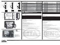
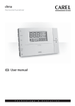
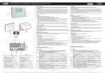
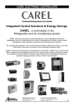
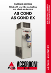
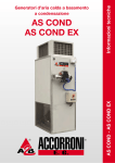
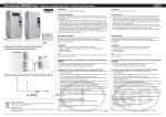
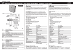
+050000790 - rel. 1.4 - 18.04.2013
CLIMA
Controllo digitale per temperatura/umidità / Digital temperature/humidity controller
Fig. 1
M od
Mo d
e
Mo d
e
e
Caratteristiche generali
General features
Il clima è uno strumento elettronico che consente, a seconda del modello scelto, la regolazione della temperatura e dell’umidità di un ambiente.
In particolare per l’umidità il clima è il terminale utente remoto, con sonda di umidità integrata o da condotta, per la gestione dell’umidificatore CAREL
“compactsteam”.
Può essere utilizzato in varie modalità di funzionamento. A seconda del modello scelto esegue funzioni speciali come la compensazione del setpoint
con la sonda di temperatura esterna. La configurazione dell’ingresso digitale per la gestione di allarmi o l’accensione e spegnimento remoto dello
strumento. Particolare attenzione si è fatta per gli algoritmi avanzati in funzionamento invernale, estivo o automatico. Funzioni speciali per il controllo
del riscaldamento a pavimento, pavimenti radianti in modalità raffrescamento e funzioni di compensazione di temperatura. Timer e clock RTC
(opzionale) per funzionamento giorno e notte. Per una dettagliata descrizione di tutte le modalità di funzionamento si consulti il manuale
tecnico (cod. +030220640 italiano, +030220641 inglese). L’opzione di controllo remoto tramite supervisore (attraverso l’acquisto dell’accessorio
IROPZ48500) permette il monitoraggio e la registrazione dei dati provenienti dallo strumento.
Clima is an electronic instrument that, based on the model chosen, controls the ambient temperature and humidity.
As specifically regards humidity control, Clima represents the remote user terminal, with the humidity probe either built-in or in the duct, for the CAREL
“compactsteam” humidifier.
The device can be operated in various modes. Depending on the model chosen, special functions are available, such as set point compensation
based on the outside temperature probe reading. The digital input can be configured for managing the alarms or the remote on/off of the instrument.
Special attention has been paid to advanced algorithms in heating, cooling or automatic operation. Special functions for the control of underfloor
heating, underfloor cooling and temperature compensation functions. Timer and real-time clock (optional) for day and night operation. For a detailed
description of all the operating modes, see the technical manual (cod. +030220640 italian version, +030220641 english version).
The supervisor remote control option (purchasing the accessory code IROPZ48500) allows the data from the instrument to be monitored and
saved.
Installazione
Installation
Sezionare l’alimentazione del controllo e dei carichi prima di intervenire sullo strumento.
Per eseguire una corretta installazione dello strumento, si seguano i seguenti passi:
• separare il frontale dalla parte posteriore facendo leva sull’apposita linguetta come mostrato in figura 2.
• Fissare lo strumento al muro in posizione orizzontale in modo da permettere il ricircolo dell’aria. Per avere una misura accurata, posizionare lo
strumento lontano da fonti di calore o umidità, lontano da finestre o muri esterni.
• Far passare i cavi di collegamento nel foro centrale del guscio inferiore e collegarli all’apposita morsettiera facendo attenzione a rispettare le
indicazioni riportate sull’etichetta. Separare i cavi di connessione e comando da quelli dei relè. Inserire una fascetta di raggruppamento sui due
gruppi di cavi (segnale ed alimentazione, uscite relè) vicino ai morsetti.
• Selezionare attraverso i micro interruttori il tipo di funzionamento dello strumento (si veda la tabella sotto riportata per il significato delle varie
modalità).
• Ricollegare, se precedentemente scollegato, il flat di connessione tra retro e frontale facendo attenzione a seguire la corretta polarità
• Richiudere lo strumento facendo un movimento opposto a quello iniziale, ponendo attenzione che il flat di connessione non ostacoli l’operazione.
• Ai fini della sicurezza elettrica (EN60730-1), inserire la linguetta plastica ed avvitare la vite per il blocco dell’apertura dello strumento
(si veda fig. 2).
Disconnect the power supply to the controller and the loads before working on the instrument.
For correct installation, proceed as follows:
• separate the front panel from the rear part by levering the tab, as shown in Figure 2.
• Fasten the instrument to the wall horizontally, so as to allow the circulation of air. For accurate measurements, position the instrument away from
sources of heat or humidity, away from windows or outside walls.
• Pass the connection cables though the centre hole in the bottom shell and connect them to the terminal block provided, observing the markings
shown on the label. Separate the connection and control cables from the relay cables.
Place a clamp around the two groups of cables (signal and power supply, relay outputs) near the terminals.
• Use the dipswitches to select the type of operation (see the table below for the meaning of the various modes).
• Reconnect, if previously disconnected, the flat connection cable between the rear and the front panel, ensuring the polarity is correct.
• Close the instrument with the opposite movement, making sure the flat connection cable does not hinder the operation.
• To ensure electrical safety (EN60730-1), insert the plastic tab and tighten the screw to stop the instrument from opening (see Fig. 2).
OPZIONE CONNESSIONE SERIALE
Se si desidera collegare lo strumento alla linea seriale tramite linea di supervisione è necessario disporre dell’accessorio IROPZ48500. Per il corretto
funzionamento, spegnere lo strumento e connettere l’opzione a J1, come riportato in Fig. 6. Per indicazioni sulla linea seriale RS-485 si veda il foglio istruzioni
allegato all’accessorio.
OPZIONE PROGRAMMAZIONE PARAMETRI
E’ possibile utilizzare l’opzione chiave di programmazione PSOPZKEY00 o PSOPZKEYA0 per la programmazione dei parametri dello strumento. Per la
connessione, spegnere lo strumento e connettere la chiave a J1 come mostrato in Fig. 6. Per maggiori informazioni sul funzionamento della chiave fare
riferimento al relativo foglio istruzioni.
Vista inferiore
Lower view
Vista inferiore
Lower view
Fig. 2
2
1
3 4
5
6
7
8
9
11
10
Fig. 3
Descrizione
Description
Rif.
1 Modalità impostazione set point della grandezza attiva sul display grande Set point setting mode for the value on the large display
2
3
4
5
6
7
8
9
10
11
Campo LARGE. Visualizza temperatura/umidità
LARGE field. Displays temperature/humidity
Selezione modalità di funzionamento Sleep
Select Sleep operating mode
Modalità Lock. Il parametro è già stato impostato
Lock mode. The parameter has already been set
Fasce orarie attive o visualizzazione Clock
Time bands active or display Clock
Selezione temperatura esterna/interna - massima/minima
Select temperature: inside/outside - maximum/minimum
Modalità di funzionamento AUTO
AUTO operating mode
OPZIONE SONDA DIGITALE DI UMIDITA’ ESTERNA
E’ possibile utilizzare la sonda digitale di umidità esterna cod. ADCF006500 in tutti i modelli con cod. ADCA000**0 in cui non è prevista la sonda di
umidità interna. Per connettere la sonda esterna spegnere lo strumento e collegare come riportato in Fig. 6.
AVVERTENZE GENERALI
Evitare l’installazione delle schede in ambienti che presentino le seguenti caratteristiche:
• Forti vibrazioni o urti.
• Esposizione a getti d’acqua.
• Elevate interferenze magnetiche e/o radiofrequenze (ad esempio vicino ad antenne trasmittenti).
• Esposizione all’irraggiamento solare diretto e agli agenti atmosferici in genere.
• Per pulire il display usare un panno morbido. Non usare acqua o solventi.
• L’uso a temperature particolarmente basse può causare una visibile diminuzione della velocità di risposta del display. Questo è da ritenersi normale
e non è indice di malfunzionamento.
• Una tensione di alimentazione elettrica diversa da quella prescritta può danneggiare seriamente lo strumento.
• Separare i cavi del controllo dai cavi che alimentano carichi induttivi e di potenza per evitare possibili disturbi elettromagnetici. Non
inserire nelle stesse canaline (comprese quelle dei cavi elettrici) cavi di potenza e cavi di comunicazione seriale. Evitare che i cavi di comunicazione
siano installati nelle immediate vicinanze di dispositivi di potenza (contattori, dispositivi magnetotermici o altro).
I cavi che escono dal controllo comunque non devono essere a vista, bensì passare all’interno del canale.
• Qualora l’apparecchio venisse utilizzato in un modo non specificato dal costruttore, la protezione prevista dall’apparecchio potrebbe essere
compromessa.
OPERAZIONI FONDAMENTALI DELLO STRUMENTO
Si riporta di seguito il significato dei tasti in condizioni normali di funzionamento:
TASTO
Power
C/F
SET
Modalità impostazione set point della grandezza attiva sul display piccolo Set point setting mode for the value on the small display
Funzionamento estate/inverno. Simbolo rampa accesa: il relè relativo alla
regolazione di temperatura è attivo
Funzionamento deumidifica/umidifica. Rampa accesa: il relè relativo alla
regolazione di umidità è attivo
Campo SMALL. Visualizza temperatura/umidità o relativi set point
Cooling/heating mode. Ramp symbol on: the temperature
control relay is active
Dehumidify/humidify mode. Ramp symbol on: the humidity
control relay is active
SMALL field. Displays temperature/humidity or corresponding
set points.
Disposal of the product
Important warnings:
The appliance (or the product)
must be disposed of separately
in compliance with the local
standards in force on waste
disposal.
The CAREL product is a state-of-the-art device, whose operation is specified in the technical
documentation supplied with the product or can be downloaded, even prior to purchase, from
the website www.carel.com. The customer (manufacturer, developer or installer of the final
equipment) accepts all liability and risk relating to the configuration of the product in order to reach
the expected results in relation to the specific final installation and/or equipment. The failure to
complete such phase, which is required/indicated in the user manual, may cause the final product
to malfunction; CAREL accepts no liability in such cases. The customer must use the product only
in the manner described in the documentation relating to the product. The liability of CAREL in
relation to its products is specified in the CAREL general contract conditions, available on the
website www.carel.com and/or by specific agreements with customers.
PRG
SIGNIFICATO
Accensione/spegnimento dello strumento. La funzione del tasto può essere inibita, se l’ accensione/spegnimento è associoata
all’ingresso digitale. Quando si spegne lo strumento tutte le regolazioni vengono disabilitate eccetto la funzione antigelo.
Seleziona la modalità di visualizzazione della temperatura tra gradi Celsius e Fahrenheit.
Ad ogni pressione corrisponde una commutazione sulla temperatura.
il setpoint visualizzato sul campo SMALL. Se premuto per più di 5s si
Permette di visualizzare ed eventualmente cambiare tramite i tasti
accede al menù parametri.
Per scorrere i vari parametri utilizzare
. Per modificarli premere una seconda volta il tasto SET e per uscire dal menù parametri
premere il tasto PRG.
Attiva la modalità di funzionamento inversa rispetto a quella attuale (sleep se si è in modalità day o day se si è in modalità sleep), per il
tempo visualizzato.
Per cambiare o azzerare il timer utilizzare i tasti
per incrementare o decrementare il tempo. Premere una seconda volta per uscire
e tornare al menù principale. Se la modalità è già attiva premendo il tasto si vede il tempo residuo alla scadenza del timer.
Accede al menù per l’impostazione del clock, delle fasce orarie, e del valore di default del timer
. Alla prima pressione del tasto
. Per impostare un nuovo valore premere SET quando
visualizza l’ora attuale (rtc), per visualizzare gli altri parametri utilizzare le frecce
è visualizzato il parametro di interesse e cambiare il valore tramite i tasti
. Premere una seconda volta per uscire e tornare al menù
principale.
Accede al menù per la visualizzazione della temperatura esterna attuale, massima e minima dall’ultima accensione dello strumento. Per
.
visualizzare le varie temperature si utilizzi
Per il loro significato si guardi il riquadro con il simbolo della casa. Si prema il tasto PRG per tornare al menù principale.
Da menù principale incrementa il valore di setpoint visualizzato sul campo grande. Dagli altri menù visualizza le variabili o i parametri
oppure ne modifica il valore se preceduto dalla pressione del tasto SET.
Da menù principale decrementa il valore di setpoint visualizzato sul campo grande. Dagli altri menù visualizza le variabili o i parametri
oppure ne modifica il valore se preceduto dalla pressione del tasto SET.
SERIAL CONNECTION OPTION
To connect the instrument to the supervisor serial line, the accessory code IROPZ48500 is required. For correct operation, turn the instrument off
and connect the option to J1, as shown in Fig. 6. For details on the RS485 serial line, see the instruction sheet enclosed with the accessory.
PARAMETER PROGRAMMING OPTION
The optional programming key code PSOPZKEY00 or PSOPZKEYA0 can be used to program the parameters on the instrument. To connect the key,
turn the instrument off and connect the key to J1, as shown in Fig. 6. For further information on the operation of the key, see the corresponding
instruction sheet.
EXTERNAL DIGITAL HUMIDITY PROBE OPTION
The external digital humidity probe code ADCF006500 can be used on all models with code ADCA000**0 if the internal humidity probe is not used.
To connect the external probe, turn the instrument off and connect the probe as shown in Fig. 6.
GENERAL WARNINGS
Avoid installing the boards in environments with the following characteristics:
• Strong vibrations or knocks.
• Exposure to jets of water.
• Strong magnetic and/or radio frequency interference (for example, near transmitting antennae).
• Exposure to direct sunlight and to the elements in general.
• To clean the display use a soft cloth. Do not use water or solvents.
• Operation at particularly low temperatures may cause an evident decrease in the response speed of the display. This should be considered
normal and does not indicate a malfunction.
• A power supply voltage other than that specified may seriously damage the instrument.
• Separate as much as possible the control cables from the cables to the inductive loads and power cables to avoid possible electromagnetic
disturbance. Never insert power cables (including the electrical cables) and probe and serial communication cables in the same conduits.
Do not install the communication cables in the immediate vicinity of power devices (contactors, circuit breakers or similar).
The cables that come out of the controller must not be in view, but rather run inside the conduit.
• If the appliance is used in a manner not specified by the manufacturer, the rated protection of the appliance may be compromised.
FUNDAMENTAL OPERATIONS OF THE INSTRUMENT
Below is the meaning of the buttons in normal operating conditions:
BUTTON MEANING
Power
Switch the instrument On/Off. The button may be disabled, if the On/Off function is associated with the digital input.
When the instrument is switched off, all controls are disabled, except for the antifreeze function.
C/F
Selects the temperature display mode, between degrees Celsius and Fahrenheit. When pressed switches between the two temperature
units.
SET
buttons, the set point displayed in the SMALL field. If pressed for more than 5 seconds,
Used to display and when necessary set, using the
accesses the parameters menu.
To scroll the various parameters, use
. To set the parameters, press the SET button again, and to exit the parameters menu, press the PRG
button.
Activates the opposite operating mode to the current mode (sleep when in day mode or day when in sleep mode), for the time displayed.
To change or reset the timer, use
to increase or decrease the time. Press again to exit and return to the main menu. If the mode
is already active pressing the button will show the time remaining until the timer expires.
PRG
Accesses the menu for setting the clock, the time bands, and the default value of the timer
. AWhen first pressing the button, the
current time is displayed (RTC); to display the other parameters, use the arrows
.
To set a new value press SET when the required parameter is displayed and change the value using
. Press again to exit and return
to the main menu.
Accesses the menu for displaying the current outside temperature, and the maximum and minimum since the instrument was last
switched on. To display the various temperatures press
.
For the meanings see the box with the house symbol. Press the PRG button to return to the main menu.
From the main menu increases the value of set point displayed in the large field. From the other menus displays the variables or the
parameters or alternatively changes the value if first pressing SET.
From the main menu decreases the value of set point displayed in the large field. From the other menus displays the variables or the
parameters or alternatively changes the value if first pressing SET.
2
1
R2
1(1)A
Output 2
2
3
Output 1
1
R2
1(1)A
Output 2
R1
1(1)A
Output 1
2
3
4
G0
24V
Power 1VA,50/60Hz
supply
22–35V
G
Power 1VA,50/60Hz
supply
22–35V
6
7
Analog output
G0
NTC ext.
G0
24V
5
Analog output
8
G
G0
NTC ext.
Digital input
24V
5
G0
Power 1VA,50/60Hz
supply
22–35V
6
Analog output
8
5
G
6
7
G0
8
NTC ext.
9
10
Digital input
R1
1(1)A
4
7
9
R2
1(1)A
9
10
10
24V Digital input
11
Fig. 4
Code
ADCA000100
ADCA000110
ADCD000100
ADCD000110
Code
ADCA000210
ADCF000210
Code
ADCA000410
ADCF000410
ADCF000610
Nome
T
Dip 1 Dip 2 Dip 3 Modello
√
Off
On
Off Regolazione base di sola temperatura con un solo relè.
Uscita analogica associata alla temperatura
T2
Off
Off
On
Regolazione doppio stadio solo estate o inverno di sola temperatura
con 2 relè. Uscita analogica associata alla temperatura
T2A
Off
On
On
Regolazione doppio stadio di tipo automatico estate inverno di sola
temperatura con 2 relè. Uscita analogica configurabile estate inverno.
H
On
Off
Off Regolazione base di sola umidità con un solo relè. Uscita analogica
associata all’umidità
T+H
On
On
Off Regolazione base di temperatura e umidità. Un relè associato alla temperatura e uno all’umidità. Uscita analogica associata all’umidità relativa
T2+H
On
Off
On
Regolazione doppio stadio solo estate o inverno di temperatura e umidità con 2 relè associati alla temperatura.
Uscita analogica associata all’umidità
T2A+H
On
On
On
Regolazione doppio stadio di tipo automatico estate inverno di
temperatura e umidità con 2 relè associati alla temperatura.
Uscita analogica associata all’umidità
T+H rad. Off
Off
Off Modello per regolazione ON/OFF per impianti radianti.
uscita
R2
T+H rad. Off
On
Off Modello per regolazione proporzionale per impianti radianti.
prop
√
√
√
√
√
√
√
√
√
√
√
√
uscita
R2
uscita
R1
uscita
R1
uscita
R1
√
FANCOIL
Set
SLEEP
CLOCK
TABELLA ERRORI
Codice Visualizzato
ALE
EE
E1
E2
Eth
Ert
EHI
ELo
ELn
°C/°F
86 mm
MODE
Relè associati alla funzione di riscaldamento (mod. inverno) e/o umidifica.
Relè associati alla funzione di raffrescamento (mod. estate) e/o deumidifica
Attenzione: la modalità di funzionamento può essere cambiata con lo strumento acceso o spento. Quando questa viene cambiata viene chiesto se si
vogliono utilizzare i parametri di default per quella modalità. Se sì, premere SET, tasto UP e SET di nuovo. In caso contrario solo PRG per uscire.
POWER
Prg
TEMP
30
43.25 mm
135 mm
83.5 mm
Fig. 5
ON
4
3
2
1
Micro-interruttori di selezione
Setting dipswitches
J1
Connessione seriale tramite accessorio
/ Serial connection via accessory:
IROPZ48500
Connessione chiave programmazione parametri /
Connection for parameter programming key
IROPZKEY00
IROPZKEYA0
J2
Connessione per sonda digitale di umidità esterna
Connection for external digital input
CAREL INDUSTRIES HQs
Via dell’Industria, 11 - 35020 Brugine - Padova (Italy)
Tel. (+39) 0499716611 – Fax (+39) 0499716600 http://www.carel.com – e-mail: [email protected]
Name
T
Dip 1 Dip 2 Dip 3 Modell
√
Off
On
Off
Basic temperature control with one relay only.
Analogue output associated with temperature
T2
Off
Off
On
Two stage temperature control, cooling or heating, with 2 relays.
Analogue output associated with temperature
T2A
Off
On
On
Automatic two stage temperature control, cooling or heating, with 2 relays. The analogue output can be configured for cooling or heating.
H
On
Off
Off
Basic humidity control with one relay only.
Analogue output associated with humidity.
T+H
On
On
Off
Basic temperature and humidity control. One relay is associated with
temperature control and one with humidity control.
Analogue output associated with relative humidity.
T2+H
On
Off
On
Two stage temperature and humidity control, cooling or heating, with 2
relays associated with temperature.
Analogue output associated with humidity
T2A+H
On
On
On
Automatic two stage temperature and humidity control, cooling or
heating, with 2 relays associated with temperature.
Analogue output associated with humidity
T+H rad. Off
Off
Off
Model for radiant systems, with ON/OFF control.
R2
OUT
T+H rad.
prop
Switch 4
ON
OFF
Possible operating mode for modells:
Descrizione
Allarme esterno generato da ingresso digitale. Se impostato da parametro
Allarme memoria parametri. Blocca la regolazione dello strumento fino a quando non sono caricati i parametri di default
Allarme sonda di temperatura interna
Allarme sonda di temperatura esterna
Allarme sensore digitale di temperatura o umidità (solo nei modelli previsti)
Allarme orologio real time clock (solo nei modelli previsti)
Allarme di alta temperatura in funzionamento invernale (mod. pavimento radiante)
Allarme di bassa temperatura in funzionamento estivo (mod. pavimento radiante)
No link: è stato impostato il controllo delle uscite dal supervisore ed è mancato il collegamento (parametro Lin = on)
CARATTERISTICHE TECNICHE
• Tensione di alimentazione: 24 Vac +10% -15% 50/60Hz 1 VA , 24-32 Vdc 1W, alimetazione di sicurezza in classe II sezione min. 0,5 mm2
• Condizioni di funzionamento: 0T60°C , 10-90%RH non condensante
• Condizioni di immagazzinamento: -20T70°C , 10-90%RH non condensante
• Dimensioni (mm): 135x86x36mm;
• Grado di Inquinamento: grado 2;
• Classe e struttura del software: A;
• Tipo azioni: 1C
• Grado di protezione contro gli agenti atmosferici: IP20;
• Temperatura della ball pressure test sulle plastiche dell’involucro frontale: 100 °C;
• Temperatura della ball pressure test sulle plastiche dell’involucro posteriore: 125 °C;
• Classificazione secondo protezione contro scosse elettriche: II, da integrare in apparecchi di classe I o II;
• Periodo sollecitazioni elettriche delle parti isolanti: lungo;
• Dispositivo di comando previsto per essere fornito a: costruttori, installatori e manutentori;
• Immunità contro sovratensioni: categoria II;
• Sezione dei conduttori (mm2): da 0,5 a 1,5 mm2;
• Precisione della misura di temperatura interna: +/- 1°C
• Precisione della misura di temperatura esterna: NTC (standard 10k) range –40 + 60 °C precisione +/- 0,5 °C + precisione sensore,
+/- 1°C da 0 a 40 °C, +/- 1,5 °C oltre
• Uscita analogica 0-10V non isolata per regolazione proporzionale: precisione +/-5% carico max 5 Kohm, corrente max 2 mA
• Omologazioni uscite relè: EN60730-1: NO 1(1)A 250Vac cos j = 0,4 ; 100.000 cicli
UL-873: NO 1A resistivo 24Vac, 30 Vdc, 100.000 cicli/PILOT DUTY: 24Vac, spunto 15A, continui 1A 30.000 cicli
• Precisione della misura di umidità (nei modelli previsti): +/- 3%rh a 25C , +/- 5% rh da 0 a 60 °C, range 10-90 % Rh
COLLEGAMENTI
• ingresso digitale:
– versione non isolata: collegamento diretto del contatto pulito; corrente di chiusura contatto: 3-5 mA .
– versione isolata con alimentazione esterna con contatto 24 Vac: alimentazione esterna di sicurezza in classe II separata dai 24 Vac dello
strumento (Fig. 4b)
• Collegamento sonda esterna con sonde standard Carel ( 10K 25°C B=3435):
– lunghezza massima: 30 m con cavo sezione min 0,5 mm2.
• Collegamento ingresso digitale: lunghezza massima 10 m, cavo sezione min. 0,5 mm2.
• Collegamento uscita analogica: lunghezza massima 10 m, cavo sezione min. 0,5 mm2.
• Collegamenti uscite relè: lunghezza massima 30 m, cavi sezione da 1,5 a 2,5 mm2, isolamento rinforzato in classe II rispetto allo strumento.
Isolamento principale tra i relè.
• Indicazioni UL per le connessioni:
- Si utilizzino conduttori di rame omologati per una temperatura di 75°C. Sezione minima AWG 22-14 rigido o flessibile.
- Per la chiusura dei morsetti si consiglia di applicare una coppia alle viti di 4 Lb-In per i morsetti di colore verde (PTR) e una coppia di 7 Lb-In
per i morsetti di colore nero (SAURO).
- Per utlizzare lo strumento in conformità alla normativa UL-873 è possibile collegare un carico con tensione massima 24 Vac, classe II, uscita relè.
AVVERTENZA: Tutti i collegamenti salvo i relè devono essere connessi a circuiti a bassissima tensione con isolamento rinforzato.
A
AD DCA
CA 00
00 010
01 0
AD 10
AD CD
CD 00
00 010
01 0
AD 10
AD CA
CA 00
00 02
04 10
AD 10
AD CF
CF 00
00 02
04 10
AD
1
CF 0
00
06
10
1
Output 2
Regolazioni consentite per modello:
A
AD DCA
CA 00
00 010
01 0
AD 10
AD CD
CD 00
00 010
01 0
AD 10
AD CA
CA 00
00 02
04 10
AD 10
AD CF
CF 00
00 02
04 10
AD
1
CF 0
00
06
10
Collegamenti elettrici / Electrical connections
Off
Switch 4
ON
OFF
On
Off
√
√
√
√
√
√
√
√
√
√
√
√
R2
OUT
R1
OUT
R1
OUT
R1
OUT
√
Model for radiant systems, with proportional control.
Relays associated with the heating and/or humidification function
Relays associated with the cooling and/or dehumidification function
Important: the operating mode can be changed with the instrument on or off. When the mode is changed, the user is asked whether to use the
default parameters for that mode. If yes, press SET, tasto UP and SET again. Otherwise press PRG to exit.
TABLE OF ERRORS
Code displayed
Description
ALE
EE
E1
E2
Eth
Ert
EHI
ELo
ELn
External alarm generated by the digital input. If set from parameter
Parameter memory alarm. Stops control of the instrument until the default parameters are loaded
Inside temperature probe alarm
Outside temperature probe alarm
Digital temperature or humidity sensor alarm (only in the models where featured)
Real time clock alarm (only in the models where featured)
High temperature alarm in heating operation (radiant floor)
Low temperature alarm in cooling operation (radiant floor)
No link: control of the outputs by supervisor has been set, but there is no connection (parameter Lin = on)
TECHNICAL SPECIFICATIONS
•
•
•
•
•
•
•
•
•
•
•
•
•
•
•
•
•
Power supply: 24 Vac +10% -15% 50/60Hz 1 VA, 24-32 Vdc 1W
Operating conditions: 0T60°C, 10-90%RH non-condensing
Storage conditions: -20T70°C, 10-90%RH non-condensing
Dimensions (mm): 135x86x36mm;
Degree of pollution: degree 2;
Software class and structure: A;
Actions type: 1C
Index of protection: IP20;
Ball pressure test temperature on the plastic of the frontal case: 100 °C;
Ball pressure test temperature on the plastic of the back case: 125 °C;
Classification according to protection against electric shock: II, to be integrated into class I or II appliances;
Period of electrical stress across the insulating parts: long;
Control device designed to be supplied to: manufacturers, installers and maintenance personnel;
Immunity against voltage surges: category 1;
Cross-section of the wires (mm2): from 0.5 to 1.5 mm2;
Precision of the inside temperature measurement: +/- 1°C
Precision of the outside temperature measurement: NTC (standard 10k) range –40 + 60 °C precision +/- 0.5 °C + sensor precision,
+/- 1°C from 0 to 40 °C, +/- 1.5 °C above
• 0-10V analogue output, non-insulated, for proportional control: precision +/-5% max load 2 KOhm, max current 5 mA
• Approval of the relay outputs: EN60730-1: NO 1(1)A 250Vac, class II reinforced insulation from the instrument. Basic insulation between the relays.
UL-873: NO 1A resistive 24Vac, 30Vdc, 100,000 cycles/ PILOT DUTY: 24Vac, I make 15A, break 1A, 30.000 cycles.
• Precision of humidity measurement (in the models where featured): +/- 3%rh at 25C, +/- 5% rH from 0 to 60 °C, range 10-90 % Rh
CONNECTIONS
• digital input:
– non-insulated version: direct connection of the voltage-free contact; contact closing current: 3-5 mA .
– insulated version with external power supply and 24 Vac contact: class II safety external power supply separated from the 24 Vac of the
instrument (Fig. 4b)
• Outside probe connection with standard Carel probes ( 10K 25°C B=3435):
– maximum length: 30 m with min cable cross-section 0.5 mm2.
Digital input connection: maximum length 10 m, min. cable cross-section 0.5 mm2.
Analogue output connection: maximum length 10 m, min. cable cross-section 0.5 mm2.
Relay output connections: cable cross-section from 1.5 to 2.5 mm2.
Relay output:: to use the instrument in compliance with UL-873, a load with a maximum voltage of 24 Vac, class II, can be connected.
UL instructions for the connections:
- Use 75° copper (CU) conductor and wire size No. 22-14 AWG, stranded or solid
- Use Terminal tightening torque of 4 Lb-In when green (PTR) terminal block is used or 7 Lb-In when black (SAURO) terminal series is used.
WARNING: All connections, except for the relays, must be connected to low voltage circuits with reinforced insulation.
•
•
•
•
•
Fig. 6
+050000790 - rel. 1.4 - 18.04.2013