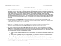
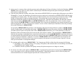
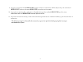
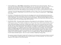
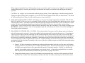
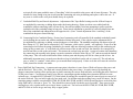
1
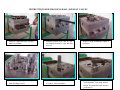
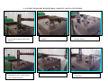
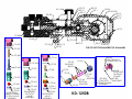
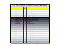
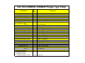
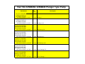
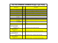
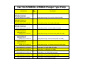
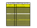
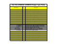
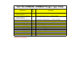
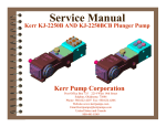
Service Manual
Kerr KD-1250B/KD-1250BCB Plunger Pump
Kerr Pump Corporation
Post Office Box 735 2214 West 14th Street
Sulphur, Oklahoma 73086
Phone: 580-622-4207 Fax: 580-622-4206
Website-www.kerrpumps.com
[email protected]
United States and Canada
800-441-8149
KERR PUMPS SERVICE MANUAL
FIFTEENTH EDITION
NEW PUMP WARRANTY
1) KERR MACHINE COMPANY (Kerr Pumps) warrants its new pumps to be free from defective materials and/or workmanship
for a period of one year from the date of sale by the Distributor, provided that the new pump is registered in accordance with
Paragraph No. 2 hereof, properly installed and operated in accordance with the Company’s Service Manual, and all other terms
of this warranty agreement are complied with by the purchaser. As hereinafter provided, this warranty includes the
replacement of parts and labor to correct any deficiency. All defective parts must be returned to the Company’s Home Office
for examination before this warranty is effective. This warranty applies to parts, which have been replaced under this warranty
only so long as the original pump warranty is effective. This warranty is for the exclusive benefit of the purchaser and is not
transferable.
2) Each Distributor of a new KERR PUMP, will provide the customer with a registration blank furnished to him by the
Company which must state the date of sale, be signed by the purchaser and the Distributor, and delivered to the Home Office
of the Company within fifteen (15) days of the date of sale.
3) In the event of a claim under this warranty, made within the one-year warranty period, the purchaser must notify the
Distributor, and the Distributor shall contact KERR PUMPS before any repairs or service calls are made.
4) All warranty claims must be sent to Kerr Pumps Home Office on the authorized warranty claim form provided by Kerr
Pumps, and available from the Distributor before any warranty claim will be considered. It is understood that Kerr Pumps
will deteriorate due to ordinary wear, therefore, the following credits shall apply to all replacement parts, labor, surface freight,
travel time and mileage allowance furnished under this warranty.
A. For the first ninety (90) days from the date of sale by the Distributor, 100% credit will be allowed on a current list price
basis.
B. From 91 to 180 days from the date of sale by the Distributor, 75% credit will be allowed on a current list price basis.
C. From 181 days to 270 days by the Distributor, 50% credit will be allowed on a current list price basis.
D. From 271 days to one year after the date of sale by the Distributor, 25% credit will be allowed on a current list price
basis.
The credit given to the Distributor for replacement parts or pumps under this warranty is based upon the Distributor’s net cost
paid Kerr Pumps for such replacement parts or pumps.
-1-
5) In the event of a warranty claim under this warranty made within ninety (90) days of the date of sale by the Distributor, KERR
PUMPS, before any repairs are made, shall be contacted by the Distributor and given the option of having the Distributor
either repair or replace the pump.
6) Upon any claim under this warranty, other than a claim wherein KERR PUMPS at its option replaced the pump as provided in
Paragraph No. 5 hereof, the Distributor will make the necessary repairs an/or replacement, and KERR PUMPS shall allow the
cost of labor on warranty claims. The labor cost may include travel time not to exceed (8) hours of actual travel time. KERR
PUMPS will pay surface freight on warranty shipments. After making the necessary repairs and/or replacements, the
Distributor will bill the customer for the full amount due for the repair. Thereafter, the Distributor will submit the warranty
claim form provided by KERR PUMPS to the KERR PUMPS Home Office for consideration. In the event the warranty
claim is honored by KERR PUMPS a Credit Memorandum will be issued to the Distributor in the amount determined by the
table in Paragraph No. 4 hereof. Thereafter, the customer’s invoice will be credited by the Distributor in the same percentage
allowed the Distributor by KERR PUMPS.
If requested by KERR PUMPS the purchaser or the Distributor shall return the alleged defective product to KERR PUMPS
factory, freight prepaid, for examination and testing. If KERR PUMPS determines the product is defective KERR PUMPS
will either repair or replace such product with a like of KERR PUMPS manufacture, f.o.b. to the Distributor or allow the
Distributor credit to an amount equal to the invoiced value of the defective product. The responsibility of KERR PUMPS is
limited to the repairing or replacing defective material manufactured by it, provided KERR PUMPS examination discloses to
its satisfaction that such material has not been altered or repaired, other than by KERR PUMPS approved procedures, subject
to misuse, improper maintenance, negligence or accident. KERR PUMPS will not be responsible for loss of liquid or for
damage of any kind, or from any cause, to any person or property of any person, or for loss of revenue of profit, or for any
other special incidental or consequential damages.
7) The warranty applies only to new KERR PUMPS. The Company specifically excludes from this warranty the following.
A. All plungers, valves, plunger packing, valve springs, seals gaskets, and corrosion and/or erosion damage caused by the
fluid handled by the Company’s pump.
B. In addition, after the expiration of the pump warranty all replacement parts are no longer in warranty.
8) In extreme cases where in the opinion of KERR PUMPS, if a pump has been misused or is being misused, KERR PUMPS
reserves the option to offer to redeem the pump from the purchaser. Should the purchaser refuse to allow the pump to be
redeemed and chooses to continue improper operation, the warranty will be void.
-2-
9) Any parts or equipment which KERR PUMPS supplies and does not manufacture shall be subject only to the warranties of
KERR PUMPS vendors to the extent KERR PUMPS can enforce such warranties.
10) Any repairs to, alterations of, or work done on alleged defective products without KERR PUMPS specific written
authorization shall void KERR PUMPS warranty applicable thereto.
11) Any action for breach of warranty or other action under this agreement must be commenced within (1) year after such cause of
action arises.
This limited warranty is in lieu of all other warranties, expressed or implied, including any implied warranty or
merchantability or fitness.
-3-
KERR TROUBLE SHOOTER GUIDE
REASON OR SERVICE NEEDED
Unusual pounding, knocking broken valve spring
Loss of pressure or volume
Consistent, rhythmic knock
Packing failure (Excessive)
Abnormal wear of fluid end parts
Abnormal wear of power end parts
Heat in power end
Insufficient fluid at high speed. Check to see if the suction line is
the proper size and is not constricted, trash in line, valve partly
opened, etc. There is also a possibility of gas in the fluid causing
the roughness.
Also above. Foreign matter may be holding valves open. Worn
valves. Broken springs.
Improper bearing adjustment. Worn bearings or connecting rods.
NOTE: Valve noise is common and normal in high-speed pumps.
It should not cause concern unless it becomes erratic.
Improper installation. Improper type lubrication.
Incorrect type packing for particular installation.
(Contact Kerr Pumps if in doubt) Excessively worn plungers.
Abrasive or corrosive fluid.
Lack of oil, overload on pump, foreign matter in oil.
A new pump will run hot for a short period (2 or 3 days). Check
above for persistent heating. Pump will operate near 140˚ F.
under average conditions.
Check for air in pump by bleeding at cover caps. Too much
spring tension Reciprocating pumps have very limited pick up,
check installation section.
-4-
INSTALLATION INSTRUCTIONS (SEE ILLUSTRATION)
The importance of proper installation cannot be overstressed. As the reciprocating pump is almost unable to lift fluid, proper
suction flooding is a must. This is the First step toward satisfactory operation.
The Kerr Pumps Engineering Service will be happy to advise you in your installation problems. As almost every installation
varies, you cannot exercise too much care in making certain your installation is proper.
Before Starting The Pump, read carefully the maintenance section in the following pages.
To start the pump, open the suction line valve and permit the intake chamber to fill on the pump. Air may be bled off by
opening the valve covers slightly until there is a constant fluid flow. After bleeding, open the discharge line valve and start the pump.
Roughness may occur from cavitation (air in line) or from starvation (lack of fluid). Eliminate these troubles before permitting
continuous operation.
-5-
RECOMMENDED INSTALLATION OF KERR PUMPS
FOR BEST RESULTS
(A)
(B)
(C)
(D)
(E)
(F)
PRESSURE RELIEF VALVE (OPTIONAL)
BY-PASSED FLUID SHOULD BE PIPED BACK IN SUCTION SUPPLY TANK WHEN POSSIBLE
USE FLEXIBLE HOSE IN DISCHARGE LINE WHEN POSSIBLE
DISCHARGE SHUT-OFF VALVE (OPTIONAL-USED FOR TOTAL SHUT-DOWN OR SERVICE ONLY)
DISCHARGE AND SUCTION ON EITHER SIDE OF FLUID END ON ALL MODELS EXCEPT ALUMINUM BRONZE
KD-1250, KJ-2250, KM-3250, & KP-3300.
PULSATION “DAMPENERS” MAY BE USED IN EITHER THE SUCTION OR DISCHARGE PIPING OR BOTH.
DISCHARGE DAMPENERS SHOULD BE CAPABLE OF HANDLING PUMP DISCHARGE MAXIMUM PRESSURE
AS A GENERAL RULE, FLUID
LEVEL MUST BE HIGHER
THAN THE PUMP FLUID END
AS PLUNGER PUMPS CANNOT
"LIFT” FLUID. ABOUT –10
FEET OF HEAD IS A GOOD
“RULE OF THUMB”.
SUITABLE
FALL-OPENING
VALVE
CAUTION SHOULD BE TAKEN TO KEEP FITTINGS OUT OF THE SUCTION AND
DISCHARGE PIPING AS THESE WILL RESULT IN POOR PERFORMANCE. EACH
90-DEGREE TURN IN THESE LINES RESULTS IN GREAT LOSS OF PUMPING
EFFICIENCY.
-6-
PREVENTIVE MAINTENANCE
DAILY
1. Check crankcase oil level.
Synthetic Lubricant:
AGMA Grade (ASTM D 2422): 4 EP
SAW Viscosity Grade (J306-8): 75W-90
ISO Viscosity Grade: 150
Viscosity in SSU @ 100OF: 625-765
KD-1250
KJ-2250
KM-3250
KZ-3150
KM-3300
KP-3300
2.
3.
4.
5.
CAPACITIES (APPROXIMATE)
2 qts.
KT-3350
16 qts.
3 qts.
KT-3400
16 qts.
4 qts.
KB-3500
20 qts.
2 qts. Use 30 wt nonKA-5500 36 qts.
detergent motor oil
4 qts.
KSB-6400 36 qts.
12 qts.
KSB-6500 36 qts.
KCP-6300 24 qts.
If pump has lubricating facilities for stuffing boxes, check level of lubricant.
Maintain packing gland tension on packing (Do not over-tighten)
Visually inspect pump for apparent trouble.
Keep the pump clean.
MONTHLY
1.
2.
3.
4.
5.
6.
7.
Drain and refill crankcase. It is recommended that oil be changed after the first week of operation.
Wash oil filler cap in kerosene.
Check valves for excessive wear, broken or bent springs, etc.
Check crankshaft bearings for endplay. (See section on crankshaft)
Keep all nuts, studs, etc. tight.
Check valve covers for leaks.
Check all seals and gaskets for leaks
-7-
GENERAL
Replace any work part before its eventual failure. Use the following instructions for removal and replacement of parts. Don’t
hesitate to call on Kerr Pumps for help if necessary.
-8-
SERVICE PROCEDURES (ALL MODELS)
1. VALVES (Wing-guided type):
A. Discharge Valves: The discharge valve and seat can be exposed by first removing the discharge valve cover cap. Once
the discharge cover cap has been removed you may lift out the discharge valve spring and the discharge valve. The
valve seat will be held in place by a taper fit and must be “pulled” with an appropriate valve-pulling tool (available
from the Kerr Pumps Dealers). Once the valve and seat have been removed they should be resurfaced or replaced if
badly worn. To replace the discharge valve, first clean and inspect the seat bore for washout defects and then drop the
seat into the bore. Replace the valve into the seat and strike the top of the valve a couple of good blows utilizing a
brass bar and hammer to seat the valve seat in the fluid end valve bore. Replace the valve spring and cover cap after
inspecting the spring and the seal of the cover cap.
B. Suction Valves: The suction valves are located in the chamber directly behind the suction or end valve cover caps.
The suction valves are serviced in the identical manner as the discharge valves. Note: Discharge valves must be
removed prior to any removal of the suction valves.
Service Procedure for KZ-3150 Valves
C. DISCHARGE VALVE: The discharge valve and seat can be exposed by first removing the discharge valve cover
plate. Once the discharge cover cap has been removed you may lift out the discharge valve spring, discharge valve
and valve seat. Once the valve and seat have been removed they should be replaced if badly worn. To replace
discharge valve, first clean and inspect the seat bore for wash out defects and then drop the seat into the bore.
Replace valve in seat then valve spring and cover cap, always-inspecting o’ring seals between seats and cover caps.
D. SUCTION VALVE: The suction valves are located in the chamber directly below the discharge valve seat. The
suction valves are serviced in the identical manner as the discharge valves.
2. VALVES (Disc-type): All disc-type valves are exposed for removal in a similar manner as the wing-guided valves. Instead
of removing the valve body; the upper portion of the valve is removed by removal of the valve capscrew, spring retainer, valve
spring, and valve spacer sleeve. The valve seat is then “pulled” from the fluid-end utilizing an authorized Kerr Valve Puller.
Note: In all Kerr Pumps with disc-type valves the discharge and suction valves are identical.
-9-
3. VALVES (Ball & Seat): In Kerr Pumps with block/billet type fluid-ends the valves are ball and seat design. These are
exposed for removal/inspection by removal of the appropriate valve cover. The flat seats are kept in place by a screw-in valve
retainer that can be best removed with a Kerr Valve Wrench made for the appropriate pump. Springs are normally
incorporated with the discharge valves while the suction valves operate with a “free ball”. A copper washer/gasket is used
under all valve seats for a seal. When installing or removing a flat type valve seat a good “rap” on top of the valve wrench will
“seat/unseat” the seat and copper gasket prior final tightening or removal. Failure to “seat” the valve seat in this manner can
result in the “washing out” of the fluid-end. For pressurized suction, valves will need to be spring loaded. Call Kerr Pumps
for this change.
4. PLUNGERS: Following the removal of the suction valve, the plunger may be removed by breaking the union between the
plunger and pony rod and forcing the plunger out the back of the fluid-end. Loosening the packing nut/gland will facilitate the
removal of the plunger. The reverse of this procedure is used to install a plunger. Lubrication and some slight force may be
used to pass plunger through the packing. Always retighten the plunger and pony rod union periodically following the removal
of the plunger to insure it is securely made up and will not vibrate loose.
5. PLUNGER PACKING: This manual includes illustrations of the packing sets for each model pump. Generally, once the
plunger has been removed from the pump, the packing can be exposed for removal by completely removing whatever device is
used to tighten the packing (i.e. the packing or stuffing box nut or gland). There will be various amounts of metal rings and
packing components depending upon the type of packing and the model of pump (refer to appropriate illustration or chart).
After the removal of all rings and equipment from the stuffing box; thoroughly clean it and inspect for damage, which might
keep the new packing from working properly. If the stuffing box is in satisfactory condition, install the new packing as per the
appropriate illustration. It is a good idea to lubricate new packing with a light oil prior to installation. Most of the standard
packing used in Kerr Pumps should be tightened with the original equipment-packing wrench while the pump is running
under normal operating pressure. After a two or three hour run-in, check the packing for tightness and re-adjust as necessary.
Packing should be checked for tightness on a periodic basis, but it is not a good idea to attempt to periodically tighten the
packing as part of routine maintenance. This tends to “wear out” the packing prematurely. When the packing leaks in an
excessive amount it should be replaced. There is no value in constantly “re-tightening” leaking packing.
If your pump is equipped with optional “spring loaded” packing, there is no adjustment in this equipment during its operational
life. The stuffing box nut is initially tightened as much as possible and there is no further adjustment. Note: In all cases the
spring goes in the stuffing box before the packing rings.
-10-
When using the optional Kevlar or Teflon packing, be sure to rotate the “splits” so that none are “aligned” to insure that the
packing holds properly. Normally, this packing is not lubricated and requires less tension on the stuffing box nut during
operation.
CAUTION: An “airtight” seal is not desirable with this plunger packing. Some slight dripage is desirable during operation.
Attempts to tighten packing until it completely “seals off” will result in premature failure from too much friction. The Kevlar
& Teflon packing must be allowed to drip a small amount to assure normal life.
6. PONY ROD and PONY ROD PACKING: Kerr Pumps use two pony rod sealing arrangements, models KD-1250, KJ-2250,
KM-3250 and KCP-6300 use a screw in seal gland, all other models use a bolt in seal gland, these glands use press in oil seals
with snap ring retainers. Some Bolt in gland use adjustable packing arrangements with bolt in or screw in followers to adjust
packing. By unscrewing plunger from pony rod a gap may be facilitated to allow the removal of the various sealing
arrangements. A special wrench will be needed to remove and replace pony rod to crosshead. (This wrench is available from
Kerr Dealers) All pony rods have a jam nut to align tighten pony rod to crosshead, care must be exercised in installing new
seal on pony rod not to damage it.
7. DISASSEMBLY OF POWER END. (CAUTION: Prior to disassembly of any power end, the plunger, pony rod, and pony
rod seal housing must be removed.) Expose the crankshaft and connecting rods by removing the pan cover. Connecting rod
caps may now be removed and the connecting rod and crosshead should be shoved all the way to the rear (toward the fluid
end) to facilitate crankshaft removal out either side as convenient. The connecting rods and crossheads may now be taken out
the front cavity exposed by removing the crankshaft. Connecting rods may be removed from the crosshead by loosening the
setscrew and driving out the wrist pin from the crosshead. A bronze bushing is used in the rod it may be driven out of the rod
and replaced with a new bushing. Reassembly is the reverse of the above outlined sequence with the following considerations
for “fits” or tolerance:
A. General: All Kerr components are machined on modern production machine tools and are of the same specifications
and close tolerances you would expect in a modern automobile engine. It must be pointed out that at top speed (350 to
400 RPM) your pump will not even be approaching idle speed for a gasoline engine so “field fits” are possible and
practical when making repairs and replacements away from the factory. All procedures outlined below are possible
with only hand tools and absolutely no instruments, special tools, or gauges are needed.
B. Connecting rod and wrist pin: Proper fit will find the wrist pin turning freely in its bore in the connecting rod, but it
should have no “wobble” that is discernable up and down the main axis of the connecting rod. This looseness in the
-11-
wrist pin fit is the most probable cause of “knocking” which is traceable to the power end of most all pumps. The only
solution for loose fitting wrist pins is to discard the connecting rod wrist pin bushing and replace with a new one. If
any wear is visible on the wrist pin it should always be replaced.
C. Crankshaft End Play and Lateral adjustments: Adjustment of the Taper Roller bearings used in all Kerr Pumps is
accomplished by removing or adding shims under the bearing housing. Shims are taken out or added until the
crankshaft (without connecting rods) will turn freely, but with no endplay felt when attempting to pull or push the
jackshaft end of the crankshaft along its long axis. Some lateral adjustment is possible by removing shims from one
side of the crankshaft and adding them to the opposite side. (Note: Lateral adjustment is the “centering” of the
crankshaft in the power frame housing.)
D. Connecting Rod to Crankshaft fitting: Factory bored connecting rods will normally fit the standard crankshaft journal
just by bolting the cap on the rod with the standard rod shims being used. If the caps do require adjustment this is
accomplished by removing or adding various thicknesses of rod shims. The standard connecting rod shim used on all
Kerr Pumps is 1/32” thick and is comprised of .002” laminates, which can be “pealed “ off separately. Proper fit of the
connecting rod will allow the pump crankshaft to be rotated while not allowing in-and-out slack in the connecting rod
along its long or main axis. A well-fitted rod will have none of the in-and-out slack, but should be free enough to be
moved from side to side on the rod journal. This insures the rod not being too tight. A point of caution when installing
the connecting rod assembly in the pump is to make certain the oil holes in the rod are “UP” and not toward the bottom
of the pump. This will result in lubrication failure in these parts and the pump will fail in a short period of time. An
additionally important step is to make sure that the rod cap is bolted back on the rod as it came off. The rod and cap
carry a “mark” or “number” which allows you to match them back properly. Failure to do this will cause the rod not to
fit the journal for which it was made.
8. Power End/Fluid End Connection: A common misconception is that there is some form of fluid seal between the power end
and the fluid end. This is false. The fluid end is merely bolted to the power frame. It can be removed by breaking the
plunger connection, backing off the packing nut or gland, removing the various fluid end bolts, and sliding the entire fluid end
off the power frame. Corrosion may tend to seize the two components together making their separation difficult in some
isolated cases. On models KP-3300 and KT-3350 the bolted in stuffing box assemblies must be removed prior to removal of
the entire fluid end. They are held in place by four studs each. On all other units the stuffing boxes can be left intact. On the
remaining pumps (with the exception KD-1250B, KJ-2250B, KM-3250B, and KCP-6300) the stuffing boxes are held in place
in the fluid end by a friction or “press” fit. They should be removed with a hydraulic press if possible. These press-in type
stuffing boxes carry a gasket and/or an o-ring to insure a good seal. The boxes on the KD-1250B, KJ-2250B, KM-3250B,
and KCP-6300 are screw-in type and carry only a copper gasket.
-12-
STUFFING BOX NUT WRENCH
AP-425
PONY ROD SEAL TOOL
KCP-KD-KJ-KM-276
VALVE WRENCH
CP-51 KCP-55
INSTRUCTIONS FOR CHANGING BALL AND SEAT VALVES
1. Remove Capscrews from Top and
End Cover Plates
2. Remove Round Cover Caps; If Caps
are difficult to remove, a pry bar may
be used
3. Inspect o’rings for damage; replace if
necessary
4. Remove valve springs and ball guides
from discharge valves
5. Use Kerr PumpValve Retainer Tool
to remove Valve Retainers
6. To unscrew valve retainer insert
Valve Retainer Tool using normal
torque. If retainer does not unscrew
go to step #7
- 2 - INSTRUCTIONS FOR CHANGING BALL AND SEAT VALVES (CONTINUED)
7. To help unscrew valve retainer, use
several firm to heavy blows with
hammer
8. Proceed to unscrew suction valve
retainer
10. Remove discharge valve retainer as
illustrated in step 7 and 8 suction
valve retainer removal
11. Proceed to unscrew discharge retainer
-3-
9. Suction valve retainer, ball and seat
assembly shown
12. Discharge and Suction valve
assemblies
- 3 - INSTRUCTIONS FOR CHANGING BALL AND SEAT VALVES (CONTINUED)
13. Remove valve seat gaskets
14. Use screwdriver or gasket removal
tool to remove old gasket
15. Valve seat gaskets must be replaced
every time valve seats are replaced
16. Suction and discharge valve retainer
ball and seat shown
17. To assemble standard suction valve
retainer: Place ball in valve retainer
before installing valve seat
18. Apply anti-seize to valve seat
- 4 - INSTRUCTIONS FOR CHANGING BALL AND SEAT VALVES (CONTINUED)
19. Install valve seat into retainer
22. Screw valve retainer to engage gasket
20. Install new gasket prior to installing
new valve retainer
21. Make sure valve tool engages valve
retainer properly
23. Torque valve retainer to 150 ft-lb
24. Use several firm to heavy blows with
hammer to seat the valve after initial
torque
- 5 - INSTRUCTIONS FOR CHANGING BALL AND SEAT VALVES (CONTINUED)
25. Re-torque to 150 ft-lbs
26. Apply anti-seize to discharge valve
seat
27. Insert valve seat in discharge valve
retainer
28. Valve seat installed in discharge
valve retainer
29. Apply anti-seize to retainer threads
30. Install new gasket prior to installing
discharge valve retainer
- 6 - INSTRUCTIONS FOR CHANGING BALL AND SEAT VALVES (CONTINUED)
31. Torque valve retainer to 150 ft-lb
32. Use several firm to heavy blows with
hammer to seat valve after initial
torque
33. Re-torque valve retainer to 150 ft-lb
34. Discharge valve ball should be
inserted after retainer has been
properly torqued
35. Discharge and suction ball guide and
springs shown for spring loaded
suction only
36. Standard Pumps do not use suction
ball guide and spring.
- 7 - INSTRUCTIONS FOR CHANGING BALL AND SEAT VALVES (CONTINUED)
37. Install cover caps. Note:
Suction Cover Cap shown is for
spring loaded suction
38. Install cover plate and capscrew.
Apply anti-seize to capscrew
threads
39. Torque to Kerr Pump specification
KD-1250B PLUNGER TYPE PUMP TORQUE SPECIFICATIONS
10
9
7
2
9
9
1
3
4
5
WHEN ADJUSTING THE ENDPLAY
OF THE TAPERED ROLLER BEARINGS
USED ON THE CRANKSHAFT,
DIAL INDICATORS AND SHIMS MUST
BE PROPERLY USED. INCORRECT
BEARING ADJUSTMENT MAY RESULT
IN EXCESSIVE NOISE, TEMPERATURE, AND
REDUCED BEARING LIFE. Kerr Pumps
RECOMMENDS BETWEEN .000” - .005”
OF INTERNAL AXIAL CLEARANCE
(END PLAY OR SIDE TO SIDE) WHEN
ASSEMBLED. FINAL ADJUSTMENT
MUST BE MADE USING A DIAL INDICATOR.
INSURE THE CONNECTING RODS ARE
DISCONNECTED TO ALLOW FREE
CRANKSHAFT MOTION.
.000"-.005" SHAFT END PLAY
.003"-.004" CONNECTING ROD AT CRANKSHAFT
.001" .002" CONNECTING ROD AT WRIST PIN
8
6
TORQUE SPECIFICATIONS
REFERENCE
1
2
3
4
5
6
7
8
9
10
DESCRIPTION
PAN COVER CAPSCREW
CONNECTING ROD CAPSCREW
BEARING HOUSING CAPSCREW
WRIST PIN SET SCREW AND JAM NUT
PONY ROD
PONY ROD PACKING GLAND
FLUID END CAP SCREW
PLUNGER TO PONY ROD
FLUID END COVER PLATE CAPSCREWS
CROSSHEAD COVER PLATE CAPSCREW
TORQUE
9 ft-lb (12 Nm)
65 ft-lb (88 Nm)
50 ft-lb (68 Nm)
12 ft-lb (16 Nm)
500 ft-lb (678 Nm)
50 ft-lb (68 Nm)
175 ft-lb (237 Nm)
300 ft-lb (407 Nm)
175 ft-lb (237 Nm)
10 ft-lb (14 Nm)
NOTE: WHEN USING LUBRICANTS,
REDUCE TORQUE AS FOLLOWS;
LUBRICANT
PERCENTAGE OF TORQUE
REDUCTION REQUIRED
OIL & GREASE
ANTI - SEIZE COMPOUND
REDUCE TORQUE 40%
REDUCE TORQUE 45%
KD-1250BCB PLUNGER TYPE PUMP TORQUE SPECIFICATIONS
10
9
7
2
1
3
4
5
WHEN ADJUSTING THE ENDPLAY
OF THE TAPERED ROLLER BEARINGS
USED ON THE CRANKSHAFT,
DIAL INDICATORS AND SHIMS MUST
BE PROPERLY USED. INCORRECT
BEARING ADJUSTMENT MAY RESULT
IN EXCESSIVE NOISE, TEMPERATURE, AND
REDUCED BEARING LIFE. Kerr Pumps
RECOMMENDS BETWEEN .000” - .005”
OF INTERNAL AXIAL CLEARANCE
(END PLAY OR SIDE TO SIDE) WHEN
ASSEMBLED. FINAL ADJUSTMENT
MUST BE MADE USING A DIAL INDICATOR.
INSURE THE CONNECTING RODS ARE
DISCONNECTED TO ALLOW FREE
CRANKSHAFT MOTION.
.000"-.005" SHAFT END PLAY
.003"-.004" CONNECTING ROD AT CRANKSHAFT
.001" .002" CONNECTING ROD AT WRIST PIN
8
6
TORQUE SPECIFICATIONS
REFERENCE
1
2
3
4
5
6
7
8
9
10
DESCRIPTION
PAN COVER CAPSCREW
CONNECTING ROD CAPSCREW
BEARING HOUSING CAPSCREW
WRIST PIN SET SCREW AND JAM NUT
PONY ROD
PONY ROD PACKING GLAND
FLUID END CAP SCREW
PLUNGER TO PONY ROD
FLUID END COVER PLATE CAPSCREWS
CROSSHEAD COVER PLATE CAPSCREW
TORQUE
9 ft-lb (12 Nm)
65 ft-lb (88 Nm)
50 ft-lb (68 Nm)
12 ft-lb (16 Nm)
500 ft-lb (678 Nm)
50 ft-lb (68 Nm)
175 ft-lb (237 Nm)
300 ft-lb (407 Nm)
175 ft-lb (237 Nm)
10 ft-lb (14 Nm)
NOTE: WHEN USING LUBRICANTS,
REDUCE TORQUE AS FOLLOWS;
LUBRICANT
PERCENTAGE OF TORQUE
REDUCTION REQUIRED
OIL & GREASE
ANTI - SEIZE COMPOUND
REDUCE TORQUE 40%
REDUCE TORQUE 45%
KD-13
KD-15
KD-17
AP-16
KD-38
KD-18
KD-1
KD-69
KD-26
KD-25-000
KD-12
KD-11
KD-10
AP-72
CP-80
KD-68
*CP-25
KD-19
KD-112
CP-35
CP-42S
KD-24
KD-32
CP-50
KD-2
KD-22
*USE CP-25C FOR PLUNGERS 7/8" & SMALLER;
CP-48S
KD-29
TWO SEALS TO
CRANKCASE OIL
CP-41
CP-42A
CP-49S
CP-50
CP-50
CP-48
CP-58
PACKING
RINGS
CP-35
CP-53
CP-59
CP-47S
CP-44-1
CP-44-2
CP-45
(OPTIONAL)
SPRING LOADED
SUCTION VALVE
ASSEMBLY
CP-47
CP-44-1
CP-44-2
CP-45
(STANDARD)
SUCTION
VALVE
ASSEMBLY
CP-60
TOP
ADAPTER
CP-49
CP-46
CP-44-1
CP-44-2
CP-45
DISCHARGE
VALVE
ASSEMBLY
CP-52
CP-60
BOTTOM
ADAPTER
KD-1250B
KD-28-A
PONY ROD
PACKING GLAND
ASSEMBLY
KD-28
PONY ROD
PACKING
GLAND
KD-28S
SNAP RING
KDB-610 CP-620
AP-16
KDB-610
KD-38
KD-69
KD-13
KD-15
KD-17
KD-18
KD-1
KD-26
KD-25-000
KD-12
KD-11
KD-10
CP-620
KDB-610
AP-72
KD-68
*CP-25
KDB-633
CP-634S
KD-32
KD-19
KD-24
KD-2
KD-22
*USE CP-25C FOR PLUNGERS 7/8" & SMALLER;
KD-112
CP-50
CP-48S
CP-635
CP-634
CP-47S
CP-50
CP-50
CP-48
CP-58
PACKING
RINGS
CP-53
CP-59
CP--49S
CP-44-1
CP-44-2
CP-45
(OPTIONAL)
SPRING LOADED
SUCTION VALVE
ASSEMBLY
CP-47
CP-44-1
CP-44-2
CP-45
(STANDARD)
SUCTION
VALVE
ASSEMBLY
CP-49
CP-46
CP-44-1
CP-44-2
CP-45
DISCHARGE
VALVE
ASSEMBLY
CP-35
KD-29
TWO SEALS TO
CRANKCASE OIL
KJ-28S
CP-60
SNAP RING
TOP
ADAPTER
KJ-28A
CP-60
PONY ROD
BOTTOM
PACKING GLAND
ADAPTER
ASSEMBLY
CP-52
KD-1250BCB
KD-28
PONY
ROD
GLAND
Kerr KD-1250B/KD-1250BCB Plunger Type Pump
Part Number
KD- 1
KD- 2
KJ-KM-KD- 3
KJ-KM-KD- 4
KJ-KM-KD- 5
KJ-KM-KD- 6
KJ-KM-KD- 7
KJ-KM-KD- 8-005
KJ-KM-KD- 8-010
KJ-KM-KD- 8-015
KJ-KM-KD- 9
KD- 10
KJ-KM-KD- 11
KD- 12
KD- 13
KJ-KM-KD- 14
KD- 15
AP- 16
KCP-KJ-KM-KD- 17
KCP-KJ-KM-KD- 18
KCP-KJ-KM-KD- 19
KCP-KD-KM-KJ- 19NB
KCP-KJ-KM-KD- 20
KCP-KJ-KM-KD- 22
KJ-KM-KD- 24
KJ-KM-KD- 24A
KJ-KM-KD- 24NB
KJ-KM-KD- 24NBA
KCP-KJ-KM-KD- 25-000
KCP-KJ-KM-KD- 25-015
KCP-KJ-KM-KD- 25-030
KCP-KJ-KM-KD- 25-045
No.
Reqd
1
1
1
1
1
12
2
As Req.
As Req.
As Req.
2
1
8
1
1
2
1
1
1
1
1
2
1
2
1
1
3
3
1
1
1
1
Description
Pump Case
Crankshaft - Heat Treated
Crankshaft Oil Seal
Bearing Housing (Blind Side)
Bearing Housing (Shaft Side)
Bearing Housing Capscrews
Bearing Housing Gaskets
Main Bearing Adjusting Shims .005
Main Bearing Adjusting Shims .010
Main Bearing Adjusting Shims .015
Main Bearings
Pan Cover
Pan Cover Capscrews
Pan Cover Gasket
Crosshead Cover Plate
Crosshead Cover Plate Capscrews
Crosshead Cover Plate Gasket
Breather Cap (Oil Filler)
Crosshead
Wrist Pin
Wrist Pin Bushing
Wrist Pin Bushing for Needle Bearing
Wrist Pin Set Screws & Nut
Connecting Rod Capscrew
Connecting Rod Only (No Inserts - Requires inserts both ends)
Connecting Rod (Inserted Both Ends)
Connecting Rod Only for Needle Bearing Wrist Pin
Connecting Rod (Inserts and Needle Bearings Both Ends)
Connecting Rod Insert Bearing (Std)
Connecting Rod Insert Bearing (.015)
Connecting Rod Insert Bearing (.030)
Connecting Rod Insert Bearing (.045)
Kerr KD-1250B/KD-1250BCB Plunger Type Pump
Part Number
KCP-KJ-KM-KD- 25-060
KCP-KJ-KM-KD- 26
KCP-KJ-KM-KD- 28
KCP-KJ-KM-KD- 28S
KCP-KJ-KM-KD- 28A
KCP-KJ-KM-KD- 29
KAB-KBB-KSB-KTB-58
KCP-33 KPB-55 KJ-KMKD- 32
KJ-KM-KD- 32C
CP-40-625 KJ-KM-KD- 68-625
CP-40-750 KJ-KM-KD- 68-750
CP-40-875 KJ-KM-KD- 68-875
CP-40-100 KJ-KM-KD- 68-100
CP-40-125 KJ-KM-KD- 68-125
CP-40T-625 KJ-KM-KD- 68T-625
CP-40T-750 KJ-KM-KD- 68T-750
CP-40T-875 KJ-KM-KD- 68T-875
CP-40T-100 KJ-KM-KD- 68T-100
CP-40T-125 KJ-KM-KD- 68T-125
KJC-KMC-KDC- 750
KJC-KMC-KDC- 875
KJC-KMC-KDC- 100
KJC-KMC-KDC- 125
KD- 69
AP- 71
AP- 72
CP-38-875 KAB-KBBKTB-52-875 KCP-49875 KPB-48-875 KSB55-875 KJ-KM-KD- 111-875
No.
Reqd
Description
1
2
1
1
1
1
Connecting Rod Insert Bearing (.060)
Connecting Rod Shims (Laminated)
Pony Rod Gland for Double Seal
Pony Rod Gland Snap Ring
Pony Rod Gland Assy (KM-28, KM-28S, 2ea of KM-29)
Pony Rod Oil Seal (Req. 2 per Gland)
1
1
1
1
1
1
1
1
1
1
Pony Rod Washer
Pony Rod Washer (Use With Pony Rod CP-25C)
Plunger 5/8" (Colmonoy)
Plunger 3/4" (Colmonoy)
Plunger 7/8" (Colmonoy)
Plunger 1" (Colmonoy)
Plunger 1 1/4" (Colmonoy)
Plunger 5/8" (Tungsten)
Plunger 3/4" (Tungsten)
Plunger 7/8" (Tungsten)
1
1
1
1
1
1
1
1
1
Plunger 1" (Tungsten)
Plunger 1 1/4" (Tungsten)
Plunger 3/4" (Ceramic)
Plunger 7/8" (Ceramic)
Plunger 1" (Ceramic)
Plunger 1 1/4" (Ceramic)
Plunger Chamber Cover
1/2" Drain Plug
1/8" Oil Level Plug
1 set
Packing 7/8"
Kerr KD-1250B/KD-1250BCB Plunger Type Pump
Part Number
No.
Reqd
Description
CP-38-100 KAB-KBBKTB-52-100 KCP-49100 KPB-48-100 KSB55-100 KJ-KM-KD- 111-100
CP-38-125 KAB-KBBKTB-52-125 KCP-49125 KPB-48-125 KSB55-125 KJ-KM-KD- 111-125
1 set
Packing 1"
1 set
Packing 1 1/4"
CP-38G-875 KAB-KBBKTB-52G-875 KCP-49G875 KPB-48G-875 KSB55G-875 KJ-KM-KD- 111G-875
1 set
858 Packing 7/8"
CP-38G-100 KAB-KBBKTB-52G-100 KCP-49G100 KPB-48G-100 KSB55G-100 KJ-KM-KD- 111G-100
1 set
858 Packing 1"
CP-38G-125 KAB-KBBKTB-52G-125 KCP-49G125 KPB-48G-125 KSB55G-125 KJ-KM-KD- 111G-125
1 set
858 Packing 1 1/4"
CP-38T-875 KAB-KBBKTB-52T-875 KCP-49T875 KPB-48T-875 KSB55T-875 KJ-KM-KD- 111T-875
1 set
Teflon Packing 7/8"
CP-38T-100 KAB-KBBKTB-52T-100 KCP-49T100 KPB-48T-100 KSB55T-100 KJ-KM-KD- 111T-100
1 set
Teflon Packing 1"
Kerr KD-1250B/KD-1250BCB Plunger Type Pump
Part Number
No.
Reqd
Description
CP-38T-125 KAB-KBBKTB-52T-125 KCP-49T125 KPB-48T-125 KSB55T-125 KJ-KM-KD- 111T-125
1 set
Teflon Packing 1 1/4"
CP-38K-875 KAB-KBBKTB-52K-875 KCP-49K875 KPB-48K-875 KSB55K-875 KJ-KM-KD- 111K-875
1 set
Kevlar Packing 7/8"
CP-38K-100 KAB-KBBKTB-52K-100 KCP-49K100 KPB-48K-100 KSB55K-100 KJ-KM-KD- 111K-100
1 set
Kevlar Packing 1"
1 set
1
Kevlar Packing 1 1/4"
Pony Rod Splash Guard
Complete Gasket Kit -- Contents
All Gaskets
All Oil Seals and Wiper Rings
Pony Rod Splash Guard
All "O" Rings
Lubrication System Complete
Check Valve Stainless Steel 1/8" Pipe
Lubrication System Less Lubricator
55 Single Pump for Forced Feed Lubricator
Crankshaft Lubrication Sheave
Lubricator Sheave
Lubricator Belt
Lubricator Bracket
Pony Rod Installation Wrench
CP-38K-125 KAB-KBBKTB-52K-125 KCP-49K125 KPB-48K-125 KSB55K-125 KJ-KM-KD- 111K-125
KJ-KM-KD- 112
KD- 113B
KD- 114
AP- 115
KD- 115
AP- 116
KJ-KM-KD- 117
AP- 117L
KJ-KM-KD- 118
KD- 119
KJ-KM-KD- 277
1
1
1
1
1
1
1
1
1
Kerr KD-1250B/KD-1250BCB Plunger Type Pump
Part Number
KDB- 610
KDB- 633S
KDB- 633SS
CP- 25
CP- 25C
KD-KJ-KM-38 CP- 33
CP- 34
No.
Reqd
3
1
1
1
1
4
1
CP- 35S
CP- 35S-625
CP- 35S-750
1
1
1
CP- 35SS
1
CP- 35SS-625
1
CP- 35SS-750
1
KB-58A KCP-45 KM-KZ107A KP-53A KPB-44A
KA-KT-55A KAB- KBBKTB-48A CP- 35A
KAB-KBB-KTB-50AB875 KCP-48AB-875
KPB-46AB-875 XP108AB-875 CP- 36AB-875
KAB-KBB-KTB-50AB100 KCP-48AB-100
KPB-46AB-100 XP-108100 CP- 36AB-100
KAB-KBB-KTB-50AB125 KCP-48AB-125
KPB-46AB-125 XP108AB-125 CP- 36AB-125
Description
Top and End Plug Cover Plate
Fluid End Vessel Only (Bolted Cap) (Cast Steel)
Fluid End Vessel Only (Bolted Cap) (316 Stainless Steel)
Pony Rod (KDB, KJB & KMB use with 1" & 1 1/4" plungers)
Pony Rod (KDB, KJB & KMB use with 5/8", 3/4" & 7/8" plungers)
Fluid End Capscrews S.S.
Fluid End Alignment Bushings (KDB, KJB, KMB)
Stuffing Box Nut (KCP, KDB, KJB, KMB) (Stainless Steel) 7/8", 1", 1
1/4"
Stuffing Box Nut (KDB, KJB, KMB) (use with 5/8" Plungers)
Stuffing Box Nut (KDB, KJB, KMB) (use with 3/4" Plungers)
Stuffing Box Nut (KCP, KDB, KJB, KMB) (Stainless Steel) 7/8", 1", 1
1/4"
Stuffing Box Nut (KDB, KJB, KMB) (use with 5/8" Plungers) (Stainless
Steel)
Stuffing Box Nut (KDB, KJB, KMB) (use with 3/4" Plungers) (Stainless
Steel)
1
Stuffing Box Nut Wrench (KDB, KJB, KMB)
1
Packing Spacer Ring 7/8" ALBZ (KCP, KDB, KJB, KMB)
1
Packing Spacer Ring 1" ALBZ (KCP,KDB, KJB, KMB)
1
Packing Spacer Ring 1 1/4" ALBZ (KCP, KDB, KJB, KMB)
Kerr KD-1250B/KD-1250BCB Plunger Type Pump
Part Number
No.
Reqd
Description
KAB-KBB-KTB-50S-875
KCP-48S-875 KPB-46S875 XP-108S-875 CP- 36S-875
1
Packing Spacer Ring 7/8" Steel (KCP, KDB, KJB, KMB)
KAB-KBB-KTB-50S-100
KCP-48S-100 KPB-46S100 XP-108S-100 CP- 36S-100
1
Packing Spacer Ring 1" Steel (KDB, KJB, KMB)
1
Packing Spacer Ring 1 1/4" Steel (KDB, KJB, KMB)
1
Packing Spacer Ring 7/8" Stainless Steel (KDB, KJB, KMB)
1
Packing Spacer Ring 1" Stainless Steel (KDB, KJB, KMB)
1
Packing Spacer Ring 1 1/4" Stainless Steel (KDB, KJB, KMB)
1
Packing Ring 7/8" ALBZ (KDB, KJB, KMB)
1
Packing Ring 1" ALBZ (KDB, KJB, KMB)
1
Packing Ring 1 1/4" ALBZ (KDB, KJB, KMB)
1
Packing Ring 7/8" Steel (KCP, KDB, KJB, KMB)
1
Packing Ring 1" Steel (KDB, KJB, KMB)
KAB-KBB-KTB-50S-125
KCP-48S-125 KPB-46S125 XP-108S-125 CP- 36S-125
KAB-KBB-KTB-50SS875 KCP-48SS-875
KPB-46SS-875 XP108SS-875 CP- 36SS-875
KAB-KBB-KTB-50SS100 KCP-48SS-100
KPB-46SS-100 XP108SS-100 CP- 36SS-100
KAB-KBB-KTB-50SS125 KCP-48SS-125
KPB-46SS-125 XP108SS-125 CP 36SS-125
KCP-47AB-875 KD-KJKM-110AB-875 CP- 37AB-875
KCP-47AB-100 KD-KJKM-110AB-100 CP- 37AB-100
KCP-47AB-125 KD-KJKM-110AB-125 CP- 37AB-125
KCP-47S-875 KD-KJKM-110S-875 CP- 37S-875
KCP-47S-100 KD-KJKM-110S-100 CP- 37S-100
Kerr KD-1250B/KD-1250BCB Plunger Type Pump
Part Number
KCP-47S-125 KD-KJKM-110S-125 CP- 37S-125
KCP-47SS-875 CP- 37SS-875
KCP-47SS-100 CP- 37SS-100
KCP-47SS-125 CP- 37SS-125
CP- 41
CP- 41-SS
CP- 42A
CP- 42A-SS
CP- 42B
CP- 42B-SS
CP- 42S
No.
Reqd
1
1
1
1
1
1
1
1
1
1
1
CPCPCPCPCPCPCPCPCP-
42S-SS
43
44
44-3
45
46
46-SS
47
47S
1
3
2
2
2
1
1
1
1
CPCPCPCPCPCPCPCPCPCP-
47S-SS
47-SS
48
48S
49
49-SS
49S
49S-SS
50
51
2
1
1
1
1
1
1
1
3
1
Description
Packing Ring 1 1/4" Steel (KDB, KJB, KMB)
Packing Ring 7/8" Stainless Steel (KDB, KJB, KMB)
Packing Ring 1" Stainless Steel (KDB, KJB, KMB)
Packing Ring 1 1/4" Stainless Steel (KDB, KJB, KMB)
Discharge Valve Plug (KCP, KDB, KJB, KMB)
Stainless Steel Discharge Valve Plug (KCP, KDB, KJB, KMB)
Suction Valve Plug (KCP, KDB, KJB, KMB)
Stainless Steel Suction Valve Plug (KCP, KDB, KJB, KMB)
End Port Plug (KCP, KDB, KJB, KMB)
Stainless Steel End Port Plug (KCP, KDB, KJB, KMB)
Suction Valve Plug Spring Loaded (KCP, KDB, KJB, KMB)
Stainless Steel Suction Valve Plug Spring Loaded (KCP, KDB, KJB,
KMB)
Plug Gasket (KCP, KDB, KJB, KMB)
Valve (Ball and Seat) (KCP, KDB, KJB, KMB)
Valve Seat O'Ring (KCP, KDB, KJB, KMB)
Valve Seat Gasket (KCP, KDB, KJB, KMB)
Discharge Valve Retainer (KCP, KDB, KJB, KMB)
Stainless Steel Discharge Valve Retainer (KCP, KDB, KJB, KMB)
Suction Valve Retainer (KCP, KDB, KJB, KMB)
Suction Valve Retainer Spring Loaded (KCP, KDB, KJB, KMB)
Stainless Steel Suction Valve Retainer Spring Loaded (KCP, KDB,
KJB, KMB)
Stainless Steel Suction Valve Retainer (KCP, KDB, KJB, KMB)
Discharge Valve Spring (KCP, KDB, KJB, KMB)
Suction Valve Spring (KCP, KDB, KJB, KMB)
Discharge Ball Guide (KCP, KDB, KJB, KMB)
Stainless Steel Discharge Ball Guide (KCP, KDB, KJB, KMB)
Suction Ball Guide (KCP, KDB, KJB, KMB)
Stainless Steel Suction Ball Guide (KCP, KDB, KJB, KMB)
Plug Seal (KCP, KDB, KJB, KMB)
Valve Retainer Tool
Kerr KD-1250B/KD-1250BCB Plunger Type Pump
Part Number
CP- 52
CP- 52-625
CP- 52-750
CP- 52M
CP- 52M-625
CP- 52M-750
CP- 52S
CP- 52S-625
CP- 52S-750
CP- 52MS
CP- 52MS-625
CP- 52MS-750
CP- 52SS
CP- 52SS-625
CP- 52SS-750
CP- 52MSS
CP- 52MSS-625
CP- 52MSS-750
CP- 53
KCP-CP- 54-150
KCP-CP- 54-175
CP- 57AB-625
CP- 57AB-750
CP- 57AB-875
CP- 57AB-100
CP- 57AB-125
CP- 57S-625
CP- 57S-750
CP- 57S-875
CP- 57S-100
CP- 57S-125
CP- 57SS-625
No.
Reqd
3
1
1
3
1
1
3
1
1
3
1
1
3
1
1
3
1
1
1
1
1
1 set
1 set
1 set
1 set
1 set
1 set
1 set
1 set
1 set
1 set
1 set
Description
Stuffing Box (KDB, KJB, KMB) (ALBZ)
Stuffing Box (KDB, KJB, KMB) 5/8" (ALBZ)
Stuffing Box (KDB, KJB, KMB) 3/4" (ALBZ)
Stuffing Box W/groove (KDB, KJB, KMB) (ALBZ)
Stuffing Box W/groove (KDB, KJB, KMB) 5/8" (ALBZ)
Stuffing Box W/groove (KDB, KJB, KMB) 3/4" (ALBZ)
Stuffing Box (KDB, KJB, KMB) (Steel)
Stuffing Box (KDB, KJB, KMB) 5/8" (Steel)
Stuffing Box (KDB, KJB, KMB) 3/4" (Steel)
Stuffing Box W/groove (KDB, KJB, KMB) (Steel)
Stuffing Box W/groove (KDB, KJB, KMB) 5/8" (Steel)
Stuffing Box W/groove (KDB, KJB, KMB) 3/4" (Steel)
Stuffing Box (Stainless Steel) (KDB, KJB, KMB)
Stuffing Box (KDB, KJB, KMB) 5/8" Stainless Steel
Stuffing Box (KDB, KJB, KMB) 3/4" Stainless Steel
Stuffing Box W/groove (Stainless Steel) (KDB, KJB, KMB)
Stuffing Box W/groove (KDB, KJB, KMB) 5/8" Stainless Steel
Stuffing Box W/groove (KDB, KJB, KMB) 3/4" Stainless Steel
Stuffing Box Gasket (KCP, KDB, KJB, KMB)
Stuffing Box Installation Tool For 1 1/2" ID Stuffing Box
Stuffing Box Installation Tool For 1 3/4" ID Stuffing Box
805 Packing Set 5/8" (KDB, KJB, KMB)
805 Packing Set 3/4" (KCP, KDB, KJB, KMB)
805 Packing Set 7/8" (KCP, KDB, KJB, KMB)
805 Packing Set 1" (KCP, KDB, KJB, KMB)
805 Packing Set 1 1/4" (KCP, KDB, KJB, KMB)
805 Packing Set 5/8" (KDB, KJB, KMB) Steel
805 Packing Set 3/4" (KCP, KDB, KJB, KMB) Steel
805 Packing Set 7/8" (KCP, KDB, KJB, KMB) Steel
805 Packing Set 1" (KCP, KDB, KJB, KMB) Steel
805 Packing Set 1 1/4" (KCP, KDB, KJB, KMB) Steel
805 Packing Set 5/8" (KDB, KJB, KMB) Stainless Steel
Kerr KD-1250B/KD-1250BCB Plunger Type Pump
Part Number
CP- 57SS-750
CP- 57SS-875
CP- 57SS-100
CP- 57SS-125
CP- 57G-625
CP- 57G-750
CP- 57G-875
CP- 57G-100
CP- 57G-125
CP- 57GS-625
CP- 57GS-750
CP- 57GS-875
CP- 57GS-100
CP- 57GS-125
CP- 57GSS-625
CP- 57GSS-750
CP- 57GSS-875
CP- 57GSS-100
CP- 57GSS-125
KZ-88V-625 CP- 58-625
KZ-88V-750 CP- 58-750
KAB-KBB-KSB-KTB-61875 KPB-60-875 KZ88V-875 CP- 58-875
KAB-KBB-KSB-KTB-61100 KPB-60-100 KZ88V-100 CP- 58-100
KAB-KBB-KSB-KTB-61125 KPB-60-125 KZ88V-125 CP- 58-125
KZ-88G-625 CP- 58G-625
KZ-88G-750 CP- 58G-750
No.
Reqd
1 set
1 set
1 set
1 set
1 set
1 set
1 set
1 set
1 set
1 set
1 set
1 set
1 set
1 set
1 set
1 set
1 set
1 set
1 set
1 set
1 set
Description
805 Packing Set 3/4" (KCP, KDB, KJB, KMB) Stainless Steel
805 Packing Set 7/8" (KCP, KDB, KJB, KMB) Stainless Steel
805 Packing Set 1" (KCP, KDB, KJB, KMB) Stainless Steel
805 Packing Set 1 1/4" (KCP, KDB, KJB, KMB) Stainless Steel
758 Packing Set 5/8" (KDB, KJB, KMB)
758 Packing Set 3/4" (KCP, KDB, KJB, KMB)
758 Packing Set 7/8" (KCP, KDB, KJB, KMB)
758 Packing Set 1" (KCP, KDB, KJB, KMB)
758 Packing Set 1 1/4" (KCP, KDB, KJB, KMB)
758 Packing Set 5/8" (KDB, KJB, KMB) Steel
758 Packing Set 3/4" (KCP, KDB, KJB, KMB) Steel
758 Packing Set 7/8" (KCP, KDB, KJB, KMB) Steel
758 Packing Set 1" (KCP, KDB, KJB, KMB) Steel
758 Packing Set 1 1/4" (KCP, KDB, KJB, KMB) Steel
758 Packing Set 5/8" (KDB, KJB, KMB) Stainless Steel
758 Packing Set 3/4" (KCP, KDB, KJB, KMB) Stainless Steel
758 Packing Set 7/8" (KCP, KDB, KJB, KMB) Stainless Steel
758 Packing Set 1" (KCP, KDB, KJB, KMB) Stainless Steel
758 Packing Set 1 1/4" (KCP, KDB, KJB, KMB) Stainless Steel
805 Pressure Rings 5/8" (KDB, KJB, KMB)
805 Pressure Rings 3/4" (KCP, KDB, KJB, KMB, KSB)
1
805 Pressure Rings 7/8" (KCP, KDB, KJB, KMB, KSB)
1
805 Pressure Rings 1" (KCP, KDB, KJB, KMB, KSB)
1
1
1
805 Pressure Rings 1 1/4" (KCP, KDB, KJB, KMB, KSB)
758 Pressure Rings 5/8" (KDB, KJB, KMB)
758 Pressure Rings 3/4" (KCP, KDB, KJB, KMB, KSB)
Kerr KD-1250B/KD-1250BCB Plunger Type Pump
Part Number
KAB-KBB-KSB-KTB61G-875 KPB-60G-875
KZ-88G-875 CP- 58G-875
KAB-KBB-KTB-61G-100
KPB-60G-100 KZ-88G100 CP- 58G-100
KAB-KBB-KTB-61G-125
KPB-60G-125 KZ-88G125 CP- 58G-125
CP- 59
CP- 59-625
CP- 59-750
CP- 60-625
CP- 60-750
KAB-KBB-KSB-KTB-63875 KCP-KPB-CP- 60-875
KAB-KBB-KSB-KTB-63100 KCP-KPB-CP- 60-100
KAB-KBB-KSB-KTB-63125 KCP-KPB-CP- 60-125
CP- 60S-625
CP- 60S-750
KAB-KBB-KSB-KTB63S-875 KCP-KPB-CP- 60S-875
KAB-KBB-KSB-KTB63S-100 KCP-KPB-CP- 60S-100
KAB-KBB-KTB-63S-125
KCP-KPB-CP- 60S-125
CP- 60SS-625
CP- 60SS-750
KAB-KBB-KSB-KTB63SS-875 KCP-KPB-CP 60SS-875
No.
Reqd
Description
1
758 Pressure Rings 7/8" (KCP, KDB, KJB, KMB, KSB)
1
758 Pressure Rings 1" (KCP, KDB, KJB, KMB, KSB)
1
1
1
1
1
1
758 Pressure Rings 1 1/4" (KCP, KDB, KJB, KMB, KSB)
*Note Pressure Ring available in Special Material
Packing Spring Only 7/8", 1", 1 1/4" (KCP, KDB, KJB, KMB)
Packing Spring Only 5/8" (KDB, KJB, KMB)
Packing Spring Only 3/4" (KCP, KDB, KJB, KMB)
Brass Adapters Only 5/8" (KDB, KJB, KMB)
Brass Adapters Only 3/4" (KCP, KDB, KJB, KMB)
1
Brass Adapters Only 7/8" (KDB, KJB, KMB)
1
Brass Adapters Only 1" (KDB, KJB, KMB)
1
1
1
Brass Adapters Only 1 1/4" (KDB, KJB, KMB)
Steel Adapters Only 5/8" (KDB, KJB, KMB)
Steel Adapters Only 3/4" (KCP, KDB, KJB, KMB)
1
Steel Adapters Only 7/8" (KDB, KJB, KMB)
1
Steel Adapters Only 1" (KDB, KJB, KMB)
1
1
1
Steel Adapters Only 1 1/4" (KDB, KJB, KMB)
Stainless Steel Adapters Only 5/8" (KDB, KJB, KMB)
Stainless Steel Adapters Only 3/4" (KCP, KDB, KJB, KMB)
1
Stainless Steel Adapters Only 7/8" (KDB, KJB, KMB)
Kerr KD-1250B/KD-1250BCB Plunger Type Pump
Part Number
No.
Reqd
Description
KAB-KBB-KSB-KTB63SS-100 KCP-KPB-CP 60SS-100
1
Stainless Steel Adapters Only 1" (KDB, KJB, KMB)
KAB-KBB-KSB-KTB63SS-125 KCP-KPB-CP 60SS-125
CP- 70
CP- 70SS
CP- 620
CP- 634
CP- 634SS
CP- 634S
CP- 634S-SS
CP- 635
CP- 635SS
CP- 636
CP- 636SS
1
1
1
12
1
1
1
1
1
1
1
1
Stainless Steel Adapters Only 1 1/4" (KDB, KJB, KMB)
Fluid End Vessel Only (KDB)
Fluid End Stainless Steel Vessel Only (KDB)
Cover Plate Capscrews
Suction Valve Plug
Suction Valve Plug (Stainless Steel)
Suction Valve Plug "Spring Loaded Suction"
Suction Valve Plug "Spring Loaded Suction" (Stainless Steel)
Discharge Valve Plug
Discharge Valve Plug (Stainless Steel)
End Port Plug
End Port Plug (Stainless Steel)
All Part Numbers Subject To Change Without Prior Notice
Not all parts are illustrated