1
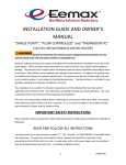
INSTALLATION INSTRUCTIONS
AND
OWNER’S MANUAL
ELECTRIC INSTANTANEOUS WATER HEATERS WITH PhD
208 and 480 VAC three phase 32 – 126 kW
600 VAC three phase 130-150 kW
BEFORE ATTEMPTING ANY INSTALLATION OR SERVICE OF THIS
HEATER, MAKE SURE THE ELECTRICAL POWER IS DISCONNECTED.
FAILURE TO FOLLOW THESE INSTRUCTIONS CAN RESULT IN
SERIOUS INJURY, DEATH AND/OR PROPERTY DAMAGE.
Read and understand these instructions thoroughly before attempting the installation or service of this water
heater. This heater must be used to heat water only and be in a location where it is not subject to freezing
temperatures. If a water softener is used, the softener must be well-maintained and in good working order.
Any maintenance issues with a water softener could be detrimental to the operation or longevity of your
Eemax tankless water heater. The manufacturer is not liable for any damages resulting from improper
installation or misuse. The warranty of this water heater will depend upon the proper installation according
to these instructions. Refer to the warranty card packaged with this heater.
This installation must conform to the latest requirements of the National Electrical Code and all applicable
state and local codes. This information is available through your local authorities. You must understand and
comply with these requirements before beginning this installation. Eemax recommends your heater be
installed by a licensed plumber and electrician. User instructions for the unit controls start on page 6.
This unit is not required by UL 499 to have a Temperature and Pressure relief valve (T&P). You should check
with local codes to find out if one is required in your area. If it is, it must be installed in the outlet hot water
pipe between the heater and the isolation valve.
This heater features a user friendly digital interface for ease of operation. Information is displayed through
a 16 character alpha numeric LCD and is controlled by 4 simple push buttons. The unit features silent
operation and internal diagnostics. The desired temperature can easily be set or altered as necessary. Once
the desired temperature is achieved, the control can be locked to avoid tampering.
EX07200-15 Rev 3
1
SAVE THESE INSTRUCTIONS
TABLE OF CONTENTS
1) MOUNTING THE HEATER TO THE WALL ………………………………………………………… PAGE 3
2) PLUMBING HOOK-UP …………………………………………………………………………………… PAGE 3
3) ELECTRICAL HOOK-UP ………………………………………………………………………………….. PAGE 4
4) COMMISSIONING THE HEATER …………………………………………………………………….. PAGE 5
5) CONTROL FEATURES ……………………………………………………………………………………. PAGE 6
6) REPAIR PARTS ……………………………………………………………………………………………. PAGE 9
7) OPTIONS …...……………………………………………………………………………………………... PAGE 11
IMPORTANT SAFETY INSTRUCTIONS
A green terminal (or a wire connector marked “G”, “GR, “Ground”, or “GROUNDING”) is provided within
the control box. To reduce the risk of electric shock, connect this terminal or connector to the grounding
terminal of the electric service or supply panel with a continuous copper wire in accordance with your
local electrical code.
Use copper conductors only.
Do not install in a bath enclosure or shower stall or connect to a salt-regenerated water
softener or a water supply of salt water.
2
1) MOUNTING THE HEATER TO THE WALL
Your heater may or may not be installed in a NEMA 4/4X cabinet. Please follow the mounting instructions
as appropriate to your installation. Whenever possible, locate the heater as close to the point of hot water
use as possible. Time-to-temperature performance will improve the closer the heater is installed to the
point of use.
This heater must be installed in a location where
it is not subject to freezing temperatures.**
Make sure the brass fittings are at the bottom of the
heater and pointing “DOWN”. No other heater
orientation is permitted. Leave a service clearance of at
least 12” inches on the left and right sides of the heater.
SafeAdvantage: Install the heater with cabinet using the
supplied mounting feet following the instructions
provided with the cabinet. Be sure to use appropriately
rated fasteners to hold the cabinet/heater in place.
SpecAdvantage: Remove the cover by removing the
cover screws as indicated by the arrows (right) and
fasten the heater to the wall using the mounting holes
located at each corner of the back plate (lower right). Be
sure to use appropriately rated fasteners to hold the
heater in place.
2) PLUMBING HOOK-UP
The heater is equipped with NPT brass fittings. Make
sure ONLY NPT fittings are used for connection to this
heater.
Make the cold water inlet connection to the lower RIGHT
fitting and the hot water outlet connection to the lower
LEFT fitting. Reversed connections will cause erratic
operation and premature heater failure.
HOT
WATER
OUT
COLD
WATER
IN
NEVER USE PIPE DOPE WHEN MAKING PLUMBING CONNECTIONS TO THIS HEATER.
FOLLOW STANDARD INDUSTRY PRACTICE WITH CAREFUL APPLICATION OF TEFLON
TAPE. DO NOT ALLOW TEFLON TAPE TO GET INTO THE HEATER.
NEVER SOLDER ANY PIPE CONNECTIONS WHILE ATTACHED TO THIS HEATER - DAMAGE
TO THE HEATER WILL RESULT. DOING THIS WILL VOID THE WARRANTY.
** Does not apply to SafeAdvantage with
Freeze Protection option.
3
Eemax requires an inlet Y-strainer with 40 mesh
strainer screen be installed for unit debris protection
and warranty coverage. Eemax also commends 2
unions, 2 full flow ball valves and two drain plugs be
installed for future serviceability. These components
are supplied by others. (See photo to right.)
Run water through the cold water inlet pipe to purge
it of any debris before making final plumbing
connections to the heater.
Open both ball valves, check for leaks and repair as needed. Finally, open all hot water outlets – one at a time
– and purge the system from any air pockets. Allow water to run until water flow is continuous and then close
the hot water outlets
3) ELECTRICAL HOOK-UP
Installation and service is to be performed by a licensed
electrician or qualified serviceman.
BEFORE BEGINNING ANY WORK ON THIS INSTALLATION, BE SURE THAT THE
ELECTRICAL BREAKER IS “OFF” AND THAT ALL MOUNTING AND PLUMBING
WORK HAS BEEN COMPLETED PER THESE INSTRUCTIONS.
This heater must have its own independent circuit using insulated, UL listed wire conductors of the
appropriate size suitable for up to 90° C and protected by the correctly rated circuit breaker.
See chart on next page.
Before starting any electrical work VERIFY there is no
power at the heater before proceeding !
L1 L2
L3 GND
The power conductors are to be secured to the L1, L2
and L3 connectors on the terminal block. The ground
is to be secured to the GND connector to the right of
the terminal block. Replace the cover.
(SpecAdvantage only).
FAILURE TO GROUND THE SYSTEM MAY RESULT IN SERIOUS INJURY,
DEATH AND/OR PROPERTY DAMAGE.
4
ELECTRICAL SPECIFICATIONS
MODEL
AP032208
AP041208
AP054208
AP064208
AP036480
AP048480
AP054480
AP072480
AP108480
AP126480
AP130600
AP150600
VOLTS
3-PHASE DELTA
208
208
208
208
480
480
480
480
480
480
600
600
Kw
32
41
54
64
36
48
54
72
108
126
130
150
AMPS
PER PHASE
89
114
150
178
44
58
65
86
130
152
130
144
RECOMMENDED
WIRE SIZE (CU) 90° C
3 AWG
2 AWG
1/0
3/0
8 AWG
6 AWG
6 AWG
3 AWG
1 AWG
2/0
1 AWG
1/0
4) COMMISSIONING THE HEATER
BEFORE SWITCHING THE ELECTRICAL BREAKER “ON”, MAKE SURE
THE INLET AND OUTLET BALL VALVES ARE FULLY OPEN AND WATER
IS FLOWING THROUGH ALL POINTS OF USE FOR A MINUTE OR TWO
UNTIL THE FLOW IS CONTINUOUS AND FREE FROM AIR POCKETS.
DO NOT SWITCH THE BREAKER “ON” IF THERE IS ANY POSSIBILITY
THE WATER IN THE HEATER IS FROZEN.
After verifying the heater has been
purged of air (see above) turn the circuit
breaker/disconnect “ON” and observe
the start-up sequence on the display.
The LCD screen will display the SETPOINT
TEMPERATURE in degrees F.
Below the display are 4 push buttons that
are used to control the function of the
heater. Press the UP or DOWN buttons to
establish your desired temperature. Refer
to the CONTROL FEATURES section of this
manual for additional information.
The heater is fully installed and ready for use.
5
TEMPERATURE RISE AT SPECIFIED FLOW RATE, DEGREES F:
MODEL
TURN-ON
GPM
3.0
GPM
4.0
GPM
6.0
GPM
8.0
GPM
12.0
GPM
20.0
GPM
25.0
GPM
30.0
GPM
AP032208
1.5
73
55
36
27
18
-
-
-
AP041208
1.5
93
70
47
35
23
-
-
-
AP054208
1.5
*
92
61
46
31
18
-
-
AP064208
1.5
*
*
73
55
36
22
17
-
AP036480
1.5
82
61
41
31
20
12
-
-
AP048480
1.5
*
82
55
41
27
16
-
-
AP054480
1.5
*
92
61
46
31
18
-
-
AP072480
2.5
*
*
82
61
41
25
20
-
AP108480
2.5
*
*
99
92
61
37
30
-
AP126480
2.5
*
*
*
*
72
43
34
29
AP130600
2.5
*
*
*
*
73
44
35
30
AP150600
2.5
*
*
*
*
85
52
40
35
* Temperature limited to preset value
5) CONTROL FEATURES
BEFORE USING THIS CONTROL, MAKE SURE ALL PRIOR INSTALLATION STEPS HAVE
BEEN PROPERLY COMPLETED, ELECTRICAL POWER IS ON AND WATER IS PRESENT
IN THE HEATER.
PUSH BUTTON FLOW CHART
1) The SETPOINT TEMP or ACTUAL TEMP screen can be
selected for display as the home screen. Either of these
screens will remain on the display when the backlight timer
expires.
OR
2) There is a 5 minute time delay built into the control.
Regardless of which screen is being displayed, after 5
minutes of inactivity, the display will revert to the SETPOINT
TEMP screen.
3) The 4 push buttons are used to control the operation of
the heater. The LEFT and RIGHT buttons shift the display
from one screen to another. The DOWN and UP buttons
may change the values within selected screens.
4) As an example, when the screen displays SETPOINT
TEMP, the desired hot water temperature will increase 1
degree for each press of the UP button and decrease 1
degree for each press of the DOWN button. Note that
minimum and maximum setpoint temperatures are
established at the factory.
6
5) The LEFT and RIGHT buttons shift the display from one
screen to another. From the INLET TEMP screen, one
press of the RIGHT button will shift the display to the
SETPOINT TEMP screen. INLET TEMP shows the actual
temperature of the water entering the heater.
6) From the SETPOINT TEMP screen, one press of the
RIGHT button will shift the display to the ACTUAL TEMP
screen. This shows the actual temperature of the water
leaving the heater.
7) From the ACTUAL TEMP screen, one press of the RIGHT
button will shift the display to the LOAD PCT screen. This
shows the electrical power consumption as a percentage
of full power.
8) From the LOAD PCT screen, one press of the RIGHT
button will shift the display to the FLOWRATE screen. This
shows the rate of flow of water through the heater.
9) From the FLOWRATE screen, one press of the RIGHT
button will shift the display to the UNITS screen. This
shows the units of measure in either the ENGLISH or
METRIC systems. ENGLISH units are degrees Fahrenheit
and gallons per minute. METRIC units are degrees Celsius
and liters per second. Use the UP and Down buttons to
select the desired units of measure.
10) From the UNITS screen, one press of the RIGHT button
will shift the display to the SOFTWARE REVISION screen.
This shows the revision level of the software in the
control.
11) From the SOFTWARE REVISION screen, one press of
the RIGHT button will shift the display to the ERRORS
screen. This shows the error history of the heater.
“0 ERRORS” means that no errors have occurred.
If the heater has an error history of 4 errors; this history
will be displayed on the screen as shown. “CODE 1:E0”
refers to the first error and indicates it to be an E0 error.
One press of the UP button will show the second error as
“CODE 2:E0” and having the same E0 error.
Continued pressing of the UP or Down buttons will scroll
through each of the errors in the history (in this case a
total of 4). ERRORS indicate an undesirable condition but
will not shut down the operation of the heater.
7
ERROR CODES:
E0: Excessive water flow detected
Corrective action: Using the OUTLET BALL VALVE, slowly reduce water flow until
the desired temperature is achieved. The temperature is proportional to the flow through the
heater; the lower the flow, the higher the temperature and vice versa.
Keep the INLET BALL VALVE fully “OPEN”. NEVER RESTRICT THE WATER
FLOW USING THE INLET VALVE.
E1: Inlet temperature too hot to generate heat
12) FAULTS are communicated through the LCD display.
The display will switch from the SETPOINT screen to the
FAULT screen and back again every 3 seconds. FAULTS
indicate an undesirable condition and will immediately
shut down the operation of the heater. If faults are
appearing on your heater call Eemax Technical Support
for assistance.
FAULT CODES:
F0: Thermistor out of range
F1: No change in water temperature detected
F2: Dry fire detected - Optical Sensor Tripped
F4: Excessive dry fire occurrences detected
13) The security of the heater settings is provided by
pressing and holding the LEFT and UP buttons for 3
seconds to lock the buttons. Once locked, the buttons
have no function. Press and hold the same LEFT and UP
buttons for 3 seconds to unlock the buttons.
[
+
]=
The security status can be checked at any time by
pressing any one button. If the system is locked, the
screen will display “BUTTONS LOCKED”.
8
13) The display can be turned off or on. Press and hold
the DOWN and RIGHT buttons for 3 seconds. If the
display is off, it can be turned on by pressing and
holding the same DOWN and RIGHT buttons for 3
seconds.
+[+ +
]=
6) REPAIR PARTS
Service and repairs are to be performed by licensed
electricians or qualified servicemen.
BEFORE ATTEMPTING ANY REPAIRS TO THE HEATER, MAKE SURE THAT THE
ELECTRICAL BREAKER IS “OFF” AND CONFIRM THAT THERE IS NO VOLTAGE AT
THE HEATER.
Contactor
Transformer
Control
Board
Emergency
Cut Off
Fuse
Optical
Sensor
Board
Hall Effect Board
(behind Flow Meter)
Flow Meter Kit **
Heating
Element
Assembly *
Triac/SSR (not shown)
* Heating element assembly consists of one heater core and wire element(s) complete.
** Flow meter kit consists of paddle wheel, dowel pin, O ring and 4 mounting screws.
9
REPAIR PARTS
Model
Transformer
Control
Board
AP032208
AP041208
AP054208
AP064208
AP036480
AP048480
AP054480
AP072480
AP108480
AP126480
AP130600
AP150600
EX08303-07
EX08303-07
EX08303-07
EX08303-07
EX08303-05
EX08303-05
EX08303-08
EX08303-08
EX08303-08
EX08303-08
EX08303-06
EX08303-06
EX08300-00
EX08300-00
EX08300-00
EX08300-00
EX08300-00
EX08300-00
EX08300-00
EX08300-00
EX08300-00
EX08300-00
EX08300-00
EX08300-00
Triac/Relay
Heating
Element
Assembly
Model
AP032208
AP041208
AP054208
AP064208
AP036480
AP048480
AP054480
AP072480
AP108480
AP126480
AP130600
AP150600
Fuse
EX198
EX08200-11
EX198
EX08200-11
N/A
N/A
EX08200-07
EX198
EX198
EX08200-11
EX08200-13
EX08200-13
Optical
Sensor
Board
Flow Meter Hall Effect
Kit
Board
EX78000-00
EX78000-00
EX78000-00
EX78000-01
EX78000-00
EX78000-00
EX78000-00
EX78000-01
EX78000-01
EX78000-01
EX78000-01
EX78000-01
EX08601-00
EX08601-00
EX08601-00
EX08601-00
EX08601-00
EX08601-00
EX08601-00
EX08601-00
EX08601-00
EX08601-00
EX08601-00
EX08601-00
Emergency
Cut Off ** Contactor
EX78002-00 EX77000-8.12 EX78001-00 EX278A-KIT
EX78002-00 EX77000-6.33 EX78001-00 EX278A-KIT
EX78002-00 EX77000-4.81 EX78001-00 EX278A-KIT
EX78002-00 EX77000-4.06 EX78001-00 EX278A-KIT
EX78002-00 EX77000-19.2 EX78001-00 EX278A-KIT
EX78002-00 EX77000-14.4 EX78001-00 EX278A-KIT
EX78002-00 EX77000-12.8 EX78001-00 EX278A-KIT
EX78002-00 EX77000-19.2 EX78001-00 EX278A-KIT
EX78002-00 EX77000-12.8 EX78001-00 EX278A-KIT
EX78002-00 EX77000-10.97 EX78001-00 EX278A-KIT
EX08200-12 EX77000-16.6 EX78001-00 EX278A-KIT
EX08200-12 EX77000-14.4 EX78001-00 EX278A-KIT
EX08306-02
EX08306-00
EX08309-00
EX08309-00
EX08306-02
EX08306-00
EX08306-02
EX08306-02
EX08309-00
EX08309-00
EX08309-00
EX08309-00
** Use EX278-A for all models EXCEPT:
- ‘S’ and ‘DB’ options use EX278D-KIT
-‘EE’ and ‘EFD’ options use EX278E-KIT
10
Addendum
INSTALLATION INSTRUCTIONS
AND
OWNER’S MANUAL
ELECTRIC INSTANTANEOUS WATER HEATERS WITH PhD
Optional GFCI, Purge Kit, & Enclosure Heater
If you need any assistance from our Technical Service Department,
make sure you can identify this water heater by having the model no: ____________________
and serial number: _____________________. Call 203-267-7890 or toll free: 800-543-6163.
Email: [email protected] Web: www.Eemax.com
Eemax Inc., 400 Captain Neville Drive, Waterbury, CT 06705
11
Optional Class 1/ Division 2
12
13
14
15
16
Optional Enclosure Heater
1) Attach heat tape and foam insulation to all
lengths of inlet and outlet water piping that are
exposed to freezing temperatures. We
recommend a rating of -30 degrees F at 10
miles per hour wind. Connect the heat tape to
an independent source of electrical power.
FAILURE TO ATTACH HEAT
TAPE AND INSULATION TO EXPOSED INLET
AND OUTLET PIPES WILL VOID THE
WARRANTY.
2) Set the thermostat on the enclosure heater,
located at the upper left corner in the
enclosure, to 40 - 70 degrees F.
Note: Heater Fan continuously operates to
recirculate air in the enclosure. The heater coil
will activate based on thermostat set point.
17
Optional GFCI
The optional GFCI consist of (A) Control Module and
(B) Current Transformer. This control module has a
LCD display indicating real-time measurements. The
GFCI module is pre-set from the factory to trip at
3.0A.
A
B
Test and reset functions are carried out automatically
every 24hrs. To manual test the GFCI press the test
button for a min. of 1.5 secs. To reset a tripped GFCI
cycle the power of the unit. If equipped with a
disconnect handle turn the handle to the “OFF”
position then back to “ON”.
Test
18
If you need any assistance from our Technical Service Department,
make sure you can identify this water heater by having the model no: ____________________
and serial number: _____________________. Call 203-267-7890 or toll free: 800-543-6163.
Email: [email protected] Web: www.Eemax.com
Eemax Inc., 400 Captain Neville Drive, Waterbury, CT 06705
19