1
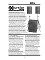
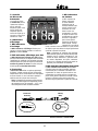
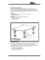
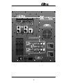
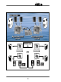
Yorkville
OWNER'S MANUAL
MANUEL DE'UTILISATEUR
TYPE: YS1031
éXcursion 2000
POWERED LOUDSPEAKER SYSTEM
Manual-Owners-EX2-1v3.pdf
IMPORTANT SAFETY INSTRUCTIONS
INSTRUCTIONS PERTAINING TO A RISK
OF FIRE, ELECTRIC SHOCK,
OR INJURY TO PERSONS.
CAUTION:
INSTRUCTIONS RELATIVES AU RISQUE
DE FEU, CHOC ÉLECTRIQUE, OU
BLESSURES AUX PERSONNES.
AVIS:
TO REDUCE THE RISK OF ELECTRIC SHOCK, DO
NOT REMOVE COVER (OR BACK).
NO USER SERVICEABLE PARTS INSIDE.
AFIN DE REDUIRE LES RISQUE DE CHOC ELECTRIQUE,
N’ENLEVEZ PAS LE COUVERT (OU LE PANNEAU
ARRIERE). NE CONTIENT AUCUNE PIECE REPARABLE
PAR L’UTILISATEUR.
REFER SERVICING TO QUALIFIED
SERVICE PERSONNEL.
CONSULTEZ UN TECHNICIEN QUALIFIE
POUR L’ENTRETIENT.
Read Instructions:
Veuillez lire le manuel:
Packaging:
Emballage:
The Owner’s Manual should be read and understood
before operation of your unit. Please, save these
instructions for future reference.
Keep the box and packaging materials, in case the unit
needs to be returned for service.
Warning:
When using electric products, basic precautions should
always be followed, including the following:
Power Sources:
Your unit should be connected to a power source only of the
voltage specified in the owners manual or as marked on the unit.
This unit has a polarized plug. Do not use with an extension cord or
receptacle unless the plug can be fully inserted. Precautions should
be taken so that the grounding scheme on the unit is not defeated.
Hazards:
Do not place this product on an unstable cart, stand, tripod, bracket or
table. The product may fall, causing serious personal injury and serious
damage to the product. Use only with cart, stand, tripod, bracket, or table
recommended by the manufacturer or sold with the product. Follow the
manufacturer’s instructions when installing the product and use mounting
accessories recommended by the manufacturer.
The apparatus should not be exposed to dripping or splashing
water; no objects filled with liquids should be placed on the
apparatus.
Terminals marked with the “lightning bolt” are hazardous live;
the external wiring connected to these terminals require installation
by an instructed person or the use of ready made leads or cords.
No naked flame sources, such as lighted candles, should be
placed on the apparatus.
Power Cord:
The AC supply cord should be routed so that it is unlikely that it will
be damaged. If the AC supply cord is damaged DO NOT
OPERATE THE UNIT.
Service:
The unit should be serviced only by qualified service personnel.
Il contient des informations qui devraient êtres comprises avant
l’opération de votre appareil. Conservez S.V.P. ces instructions
pour consultations ultérieures
Conservez la boite au cas ou l’appareil devait être
retourner pour réparation.
Attention:
Lors de l’utilisation de produits électrique,
assurez-vous d’adhérer à des précautions de bases
incluant celle qui suivent:
Alimentation:
L’appareil ne doit être branché qu’à une source d’alimentation
correspondant au voltage spécifié dans le manuel ou tel qu’indiqué
sur l’appareil. Cet appareil est équipé d’une prise d’alimentation
polarisée. Ne pas utiliser cet appareil avec un cordon de
raccordement à moins qu’il soit possible d’insérer complètement les
trois lames. Des précautions doivent êtres prises afin d’eviter que le
système de mise à la terre de l’appareil ne soit désengagé.
Risque:
Ne pas placer cet appareil sur un chariot, un support, un trépied ou une
table instables. L’appareil pourrait tomber et blesser quelqu’un ou subir des
dommages importants. Utiliser seulement un chariot, un support, un trépied
ou une table recommandés par le fabricant ou vendus avec le produit.
Suivre les instructions du fabricant pour installer l’appareil et utiliser les
accessoires recommandés par le fabricant.
Il convient de ne pas placer sur l’appareil de sources de flammes
nues, telles que des bougies allumées.
L’appeil ne doit pas être exposé à des égouttements d’eau ou des
éclaboussures et qu’aucun objet rempli de liquide tel que des vases
ne doit être placé sur l’appareil.
Les dispositifs marqués d’une symbole “d’éclair” sont des parties
dangereuses au toucher et que les câblages extérieurs connectés à
ces dispositifs de connection extérieure doivent être effectivés par un
opérateur formé ou en utilisant des cordons déjà préparés.
Cordon d’alimentation:
Évitez d’endommager le cordon d’alimentation. N’UTILISEZ PAS
L’APPAREIL si le cordon d’alimentation est endommagé.
Service:
Consultez un technicien qualifié pour l’entretien de votre appareil.
safety-4v0.pdf 04/29/03
POWERED LOUDSPEAKER SYSTEM
Introduction
The Yorkville éXcursion 2000 is the ultimate all-inone complete PA system for live sound or mobile DJ
applications. The system includes one 18-inch high
efficiency subwoofer and two specially optimized
satellite speaker enclosures. The éXcursion 2000’s
active crossover network and three amplifiers are
conveniently housed in the subwoofer enclosure. The
Class D and two 3-tier Class A/B amplifiers ensure ultra
quiet operation, low distortion and a high SPL output.
This is not a system that’s been hastily put together; the
éXcursion 2000 was designed as a complete solution.
The system assembles into an integrated package
to make it easier for transportation and storage. The
éXcursion 2000 was designed for the road.
The éXcursion 2000 can be used as a single
system (subwoofer with two satellites) or as a dual
system using two éXcursion 2000 systems. When
the éXcursion 2000 is used in a dual system
configuration, each system behaves as individual
channels. The dual-system configuration allows the
use of the two satellite speakers on each side of the
stage that can be positioned for greater dispersion. The
éXcursion 2000 subwoofer has a pole-mount adapter
built-in to eliminate the necessity of using two speaker
stands. See your Yorkville dealer for information on the
variety of poles and stands available.
1. Input Jacks
iii. Mono/Stereo Switch
In Stereo mode, the éXcursion 2000 routes the
two signals from the left and right inputs to the
corresponding satellite enclosures. If an individual
signal is sent to the éXcursion 2000, in either the
left or right channel, enabling the Mono mode will
route the signal to both satellite enclosures. If a
stereo signal is used, both the left and right will
be summed when the Mono mode is selected.
Note: Mono operation (using a single source)
will require setting the applicable level control
at a higher level.
i. Left & Right Input Jacks
The input jacks of the éXcursion 2000 are
designed for operation with line-level signals.
The XLR and balanced ¼-inch TRS jacks are
wired in parallel, functionally identical except for
the style of connector.
Note: The required input level for full power
operation, when the Level controls are set to
the center detent position, is approximately +4
dBv (1.2 volts). Increasing this setting allows
the éXcursion 2000 to be driven with sources
that have a low signal level.Connecting signals
to both types of inputs on any one channel
(XLR and ¼-inch) is not recommended.
2. Level Controls
i. Left & Right Level Controls
The Left and Right Level controls adjust
the output level of the corresponding satellite
enclosures. Adjustments can be made to alter
the balance of the satellites, compensate for
signal sources that are not the standard +4 dBv
line level or to tweak the SPL levels appropriate
to the application. The Left Level and Right
Level are normally set to the center detent.
ii. Aux Bal Subwoofer In Jack
This balanced input allows the subwoofer to be
fed from a separate signal source, other than the
signals being fed to the Left and Right amplifiers.
This feature allows the subwoofer to be mixed
separately from the Left and Right signals.
1
ii. Subwoofer
Level Control
i. Limit
Indicator LED
The Subwoofer
Level control allows
fine-tuning of the
low frequency
output. Adjustments
can be made to
compensate for
signal sources that
are not the standard
+4 dBv level.
LEFT
LEVEL
STEREO
MONO
00
dB
CLIP
LIMIT
12
INPUTS
SUB CLIP
SUBWOOFER
LEVEL
SUB LIMIT
00
LEFT
The Limit Indicator
LED indicates
when the maximum
operating level for
the satellites has
been reached.
When the LED is
illuminated, the
circuitry is actively
limiting the output.
Increasing the
input signal level
or turning up the
Level controls will
not increase the
operating level
beyond the limit
indicated. When the unit is driven into limiting, the
internal Limiter circuit becomes triggered and will
reduce the gain. This will not significantly degrade
the sound quality.
Note: Operating a few dB into limiting will
ensure that the system is operating at its
maximum output. Operating excessively into
limiting will make the system more susceptible
to feedback.
RIGHT
LEVEL
dB
12
00
dB
12
RIGHT
BAL
AUX BAL
LEFT
R I G HT
i. Clip Indicator
LEDs
The Clip Indicator
LED shows when there is ex-cessive input level on
either the Left or Right Inputs.
ii. Sub Clip Indicator LED
The Sub Clip Indicator LED indicates excessive
levels for signals going to the subwoofer
amplifier. Indications of excessive levels are
monitored either from the signals being sent from
the Left and Right Inputs or from the Aux Bal
Subwoofer In jack.
PARALLEL INPUTS
3. Clip
Indicators
PARALLEL INPUTS
SUBWOOFER IN
BAL
ii. Sub Limit Indicator LED
4. Protection
The Sub Limit Indicator LED illuminates when
the maximum recommended operating-level of
the subwoofer has been reached. Increasing the
input signal level or turning up the Level controls
will not increase the operating level beyond
the limit indicated. When the internal Limiter
circuit becomes active the sound quality will not
significantly be degraded.
The éXcursion 2000 uses a sophisticated, multistage limiting system that prevents clipping of the
amplifiers while accommodating a wide range of
input levels. The limiter circuitry protects the entire
system against most instances of overpowering.
Note: Continuous acoustic feedback may cause
damage to the light bulbs (CTL™ horn protection
circuitry) or to the speakers in the satellites.
1/4-inch T.R.S.
Phone Plug
XLR Plug
(Male)
Tip = 0°
Ring = 180°
1
2
3
Sleeve = Ground
Pin 1 = Ground
Pin 2 = 0°
Pin 3 = 180°
Balanced 1/4-inch T.R.S. to Balanced XLR
2
The éXcursion 2000 System
The Yorkville éXcursion 2000 system is shipped in two cartons. The main carton contains
the éXcursion 2000 main unit (subwoofer w/amplification) and the Dolly. The hold-down
strap is used to secure the dolly and the sub together for shipping. The second carton
contains the 2 éXcursion 2000 satellites, 4 metal casters, the power cord and these
operating instructions.
Carton 1
- éXcursion 2000 main unit (subwoofer w/amplification)
- Transportation Dolly
Carton 2
-
2 éXcursion 2000 satellite speaker cabinets
4 Swivel Casters (YS#8577)
Power Cord
Operating instructions
YS# 8577 Swivel Caster
YS# 8817 - Washer
YS# 8489 - Split Lock-Washer
YS# 8936 - Bolts
YS# 8440 - Velcro™ Strap
Some assembly required.
The bolts provided to attach the casters on the dolly have been conveniently screwed into the dolly.
This allows you to find the mounting holes and prevents the bolts from being lost in shipping.
When installing Swivel Casters follow the sequence shown in the assembly diagram above. Place
the split lock-washer (YS# 8489) between the bolt (YS# 8936) and the flat washer (YS# 8817).
Following this sequence will assure proper assembly.
- 4x YS# 8577 - Swivel Casters
- 16x YS# 8817 - Flat Washers
- 16x YS# 8489 - Split Lock-Washers
- 16x YS# 8936 - Flat Bolts
3
POWERED LOUDSPEAKER SYSTEM
SPECIFICATIONS
System Type
Active or Passive
Program Power (Watts)
Sensitivity (dB @1Watt/1m)
Max SPL (dB)
Frequency Response (Hz +/- 3db)
Crossover Frequency (Hz)
Driver Configuration
HF Driver(s)
HF Impedance (Ohms)
HF Horn
HF Dispersion (°H x °V)
HF Protection
MF Driver(s)
MF Program Power (Watts)
LF Driver(s)
LF Program Power(Watts)
LF Protection
Self Contained Loudspeaker System
Active
2x 225 / 1200
95 / 99
119 / 128
100-18k / 42-100
2200
2 1x12 inch / 1 1x18 inch
1 inch Mylar
4
ABS Plastic Custom Waveguide
90 x 30
CTL
12 inch (2 inch voicecoil)
225
18 inch (4 inch voicecoil)
1200
Excursion / Clipping / Thermal
HF Power Amplifier (Watts)
2 x 225
LF Power Amplifier (Watts)
1200
Inputs - 1/4" Jacks
2
Inputs - XLR
2
Mixer Controls
Subwoofer level control / Left and Right satellite level controls
LED Indicators
Clipping
Feet
Wheels
Yes
Dolly Board
Bar Handles
Yes
Pole Mount Adapter (1 3/8"-3.5cm)
Yes
Enclosure Materials
Grille
Covering / Finish
Optional Covering / Finishes
Other Details
15mm 11-ply birch
Curved Perforated Metal Grille
Black Ozite carpet
Black Hard Painted Finish (EX2B)
Dimensions (WxHxD in/cm):
Satellite Speakers 22.25x14.25x10.75 / 56.5x36.25x27.3
33lbs / 14.9kgs
Subwoofer 29.5x22x18.25 / 75x55.8x46.3
112lbs / 51kgs
Caster Kit (with wheels) 21.5x27.5x3.5 / 54.6x70x9
4
POWERED LOUDSPEAKER SYSTEM
L’éXcursion 2000 de Yorkville est l’ultime système
de sonorisation tout en un pour application Live ou DJ. Le
système inclut un subwoofer de 18 pouces à haute efficacité et
deux enceintes à haut-parleur spécialement conçu pour offirir
un rendement optimum lors de l’utilisation en tant qu’enceinte
satellites. Le circuit actif du crossover de l’éXcursion 2000’s et
trois amplificateurs sont intégrés à l’enceinte du subwoofer. Les
amplificateurs de classe A/B à 3 tiers et un de classe D assure une
opération ultra silencieuse, un taux de distorsion bas et un niveau de
pression sonore élevé. Ceci n’est pas un système qui a été rapiécé
rapidement; l’éXcursion 2000 a été conçu comme solution
complète. Les diverses composantes du système s’unissent en
un ensemble intégral qui facilite le transport et l’entreposage.
L’éXcursion 2000 a été conçu pour prendre la route!
L’ éXcursion 2000 peut être utilisé comme système simple
(subwoofer et deux satellites) ou comme système double
utilisant deux ensemble éXcursion 2000. Lorsque l’ensemble
éXcursion 2000 est utilisé en configuration de système
double, chaque système se comporte comme canal individuel.
La configuration à double système permet l’utilisation de
deux enceintes satellites sur chaque côté de la scène. Ces
haut-parleurs peuvent alors être placés pour offrir une meilleure
dispersion sonore. Le subwoofer de l’éXcursion 2000 est
équipé avec quincaillerie nécessaire pour y monter un poteau
qui élimine le besoin pour support de haut-parleur additionnel.
Voir votre revendeur Yorkville autorisé pour plus d’information sur la
disponibilité des divers poteaux et supports.
1. Prises d’Entrées
iii. Commutateur Mono/Stereo
En mode stéréo, l’éXcursion 2000 achemine les
signaux de gauche et droite aux enceintes satellites
correspondantes. En engageant le mode Mono vous
pouvez acheminer un signal monophonique, branché
au canal d’entrée gauche ou droite de l’éXcursion
2000, aux deux enceintes satellites. Lorsqu’un signal
stéréo est utilisé, les signaux de gauche et de droite
sont conjugués si le mode Mono est sélectionné.
Note: L’opération Monophonique (l’utilisation
d’une seule source de signal) nécessitera une
augmentation du niveau de contrôle de volume.
i. Prises d’Entrées de Gauche et Droite
Les prise d’entrées de gauche et droite de
l’éXcursion 2000 ont été conçus pour opération
avec signaux de niveau. Les prises symétriques XLR et
¼ Pointe/Bague/Manchon sont branchées en parallèle.
Les deux prises fonctionnent de façon identique.
Note: Le niveau d’entrée requis pour opération
à pleine puissance, lorsque les contrôles de
niveau sont réglés à leur position centrale, est
environ +4 dBv (1.2 volts). Une augmentation
de ce réglage permet l’utilisation de source
avec niveau plus faible pour alimenter
l’éXcursion 2000.Nous vous recommandons
de ne pas brancher simultanément des
signaux aux deux types d’entrées.
2. Contrôles de niveau
i. Contrôles de Niveau de Gauche et Droite
Les contrôles de niveau de gauche et droite
ajustent le niveau de sortie pour les enceintes
satellites correspondantes. Vous pouvez ajuster
les signaux pour altérer la balance des enceintes
satellites, pour compenser pour les sources de signal
qui ne sont pas au niveau ligne standard de +4 dBv
ou pour régler le niveau à un volume approprié pour
l’application. Les contrôles de niveau de gauche et
droite sont normalement réglés à la position centrale.
ii. Prise d’Entrée Symétrique
Auxiliaire Pour Subwoofer
Cette entrée symétrique permet d’acheminer une source
de signal séparée au subwoofer ; un signal indépendant
de celui acheminé aux amplificateurs de gauche et droite.
Cette caractéristique permet au subwoofer d’être
mélangé séparément des signaux de gauche et droite.
5
ii. Contrôle
de Niveau du
Subwoofer
i. DEL indicatrice
de limiteur
Le contrôle de niveau
du Subwoofer permet
l’ajustement de pointe
pour la sortie des
fréquences graves. Vous
pouvez ajuster pour
compenser pour les
sources de signal qui ne
sont pas au niveau ligne
standard de +4 dBv.
LEFT
LEVEL
STEREO
MONO
00
dB
RIGHT
LEVEL
CLIP
LIMIT
00
INPUTS
SUB CLIP
SUBWOOFER
LEVEL
SUB LIMIT
12
LEFT
LA DEL indicatrice de
limiteur indique que
le niveau maximum
d’opération pour les
enceintes satellites a été
achevé. Lorsque la DEL
est illuminé, le circuit
limite la sortie. Une
augmentation du niveau
du signal d’entrée ou une
augmentation du contrôle
de niveau n’augmentera
pas le niveau général
d’opération au-delà de la
limite indiquée. Lorsque
l’appareil entre en mode de
limite, le limiteur interne est activé et il a pour fonction
de réduire le gain sans affecter de façon significative la
qualité de la sonorité du système.
Note: L’opération du système avec quelque
dB au-delà du point ou le limiteur devient actif
assurera que le système fonctionne à son
niveau de sortie maximum. L’opération avec
un niveau dépassant de façon excessive
le point ou le limiteur devient actif rendra le
système plus vulnérable au feedback.
dB
RIGHT
BAL
12
00
dB
12
AUX BAL
RIGHT
i. DEL indicatrice
d’écrêtage
La DEL indicatrice d’écrêtage s’illumine pour
indiquer un niveau d’entrée excessif sur l’entrée de
gauche ou celle de droite.
ii. DEL Indicatrice d’Écrêtage pour Sub
La DEL indicatrice d’écrêtage pour Sub indique
des niveaux excessifs pour les signaux étant acheminés à
l’amplificateur du subwoofer. Les indications de niveaux
excessifs captés soit à partir des signaux provenant des
entrées de gauche et droite ou à partir de la prise
d’entrée symétrique Aux Bal Subwoofer.
PARALLEL INPUTS
LEFT
3. Indicateurs
d’Écrêtage
PARALLEL INPUTS
SUBWOOFER IN
BAL
ii. DEL Indicatrice de Limiteur Pour le Sub
La DEL indicatrice de limiteur pour le Sub
s’illumine lorsque le niveau d’opération maximum
recommandé pour le subwoofer a été atteint. Une
augmentation du niveau du signal d’entrée ou une
augmentation du contrôle de niveau n’augmentera
pas le niveau général d’opération au-delà de la limite
indiquée. Le limiteur interne peut être actif sans
affecter de façon significative la qualité de la sonorité.
4. Protection
L’éXcursion 2000 utilise un système sophistiqué
de limiteur à étages multiple qui évite l’écrêtage des
amplificateurs tout en accommodant une vaste gamme
de niveau d’entrée. Le circuit de limiteur protége le
système entier de la plupart des surcharges.
Note: Le feedback acoustique continu pourrait
causer des dommages aux ampoules (circuit
de protection pour les trompes - CTL™) ou
aux haut-parleurs des enceintes satellite.
1/4-inch T.R.S.
Phone Plug
XLR Plug
(Male)
Tip = 0°
Ring = 180°
1
2
3
Sleeve = Ground
Pin 1 = Ground
Pin 2 = 0°
Pin 3 = 180°
Balanced 1/4-inch T.R.S. to Balanced XLR
6
Le Système éXcursion 2000
Le système éXcursion 2000 de Yorkville est expédié dans deux boites de carton. Le carton
principal contient l’unité éXcursion 2000 principal (subwoofer avec amplification) et le
chariot. La courroie est utilisée pour attacher solidement ensemble le chariot et le subwoofer pour
l’expédition. Le deuxième carton contient les 2 satellites éXcursion 2000, 4 roulettes de métal, le
cordon d’alimentation et ces instructions d’opération.
Carton 1
- éXcursion 2000 unité principal (subwoofer avec amplification)
- Chariot de Transport
Carton 2
-
2 enceintes à haut-parleur satellites éXcursion 2000
4 roulettes pivotantes (YS#8577)
Cordon d’alimentation
Instructions d’opération
YS# 8577 Swivel Caster
YS# 8817 - Washer
YS# 8489 - Split Lock-Washer
YS# 8936 - Bolts
YS# 8440 - Velcro™ Strap
Assemblage Requis.
Les boulons fournis pour assembler les roulettes au chariot ont été vissés dans le chariot. Cela vous
aidera à trouver les trous de montage et aidera à ne pas perdre les boulons durant le transport.
Lors de l’installation des roulettes pivotantes suivez l’ordre illustré dans le diagramme
d’assemblage ci-dessus. Placez la rondelle de verrouillage (YS# 8489) entre le boulon (YS# 8936) et
la rondelle plate (YS# 8817). Suivre cet ordre assurera un assemblage correct.
- 4x YS# 8577 – Roulettes Pivotantes
- 16x YS# 8817 – Rondelles Plates
- 16x YS# 8489 – Rondelle de Verrouillage
- 16x YS# 8936 – Boulon Plates
7
POWERED LOUDSPEAKER SYSTEM
SPÉCIFICATIONS
Type de système
Actif ou Passif
Système de haut-parleur intégré
Actif
Puissance Nominal (Watts)
2x 225 / 1200
Sensibilité (dB @1Watt/1m)
95 / 99
Pression Sonore Max (dB)
Réponce en Fréquence (Hz +/- 3db)
Crossover Frequency (Hz)
Configuration de haut-parleurs
Driver(s) pour HF
Impedance HF (Ohms)
Trompe HF
Dispersion HF (°H x °V)
Protection HF
Driver(s) fréquences médiannes
Puissance Programme- médiannes (Watts)
Driver(s) Graves
Puissance Programme, graves(Watts)
Protection, graves
119 / 128
100-18k / 42-100
2200
2 1x12 pouces / 1 1x18 pouces
Mylar 1pouce
4
Guide d'onde sur mesure pasltique ABS
90 x 30
CTL - Absorption du courant par ampoule
12 pouces (bobine de 2 pouces)
225
18 pouces (bobine de 4 pouces)
1200
Excursion / Écrêtage / Thermique
Amplificateur de puissance/Aiguës (Watts)
2 x 225
Amplificateur de puissance/Graves (Watts)
1200
Prises d'entrée - 1/4"
2
Entrées - XLR
2
Contrôles de mélange
DEL Indicatrices
Pieds
Roulettes
Contrôle de niveau pour Subwoofer et pour enceintes satellites
gauche et droite
Écrêtage
Oui
Chariot
Poignés
Oui
Adaptateur pour poteau de montage (1 3/8"-3.5cm)
Oui
Enclosure Materials
Grille
Finition
Finition optionel
Autres détails
15mm 11-ply birch
En métal, courbé et perforré
Tapis noire
Peinture dur, noire
Dimensions (LxHxP p/cm):
Haut-parleurs Satellites 22.25x14.25x10.75 / 56.5x36.25x27.3
33livres / 14.9kgs
Subwoofer 29.5x22x18.25 / 75x55.8x46.3
112livres / 51kgs
Ensemble de roulettes
21.5x27.5x3.5 / 54.6x70x9
8
Yorkville
POWERED LOUDSPEAKER SYSTEM
LEFT
LEVEL
STEREO
MONO
00
dB
RIGHT
LEVEL
CLIP
LIMIT
SUBWOOFER
LEVEL
SUB LIMIT
12
00
INPUTS
L EF T
SUB CLIP
dB
12
00
dB
12
RI GHT
BAL
NOT E : C OO L IN G FAN DO E S NOT OP E RAT E UN TIL
T HE A MP L I F I E R R E A C HE S F U L L O P E R AT I NG T E M P ER AT U R E
AU X BA L
L EFT
RI G H T
PARALLEL INPUTS
PARALLEL INPUTS
SUBWOOFER IN
BAL
TOP FOLDED VIEW
AT T E N T IO N: QU A L I F I E D T E C H NI C I A N S ONLY ! !
T O A C C E S S I NT E RN A L E L E C T RONI CS
(A F T E R RE M OV I NG C H A S S I S F RO M C A B IN E T )
R E M OV E S E V E N S C R E W S L A B E L E D W I T H A R ROW S
LEFT SPEAKER OUTPUT
AUX BAL
SUB IN
2
3
LEFT LEVEL
1
LEFT
AMP
BALANCED
LEFT IN
LEFT SPKR
OUTPUT
MONO
∑
SUBWOOFER
STEREO
SUBWOOFER
LEVEL
2
3
RIGHT LEVEL
1
RIGHT IN
SUBWOOFER
AMP
RIGHT
AMP
BALANCED
+ (+1 PIN)
– (–1 PIN)
RIGHT SPKR
OUTPUT
NOTE: GROUND LIFT NOT REQUIRED
RIGHT SPEAKER OUTPUT
DOUBLE INSULATED, U-GND REQUIRED FOR PERFORMANCE, NOT SAFETY.
POWER
TYPE: YS1031
PUSH TO RESET
230V
50Hz 3,5A
Z640 / 1.3
Yorkville
120VAC
60Hz 7.0A
DESIGNED & MANUFACTURED BY
YORKVILLE SOUND • TORONTO, CANADA
OFF
ON
9
+ (+1 PIN)
– (–1 PIN)
DUAL OPERATION
Mixer
éXcursion 2000
System
éXcursion 2000
System
MONO Mode Selected
on éXcursion 2000s
MONO
LEFT SPEAKER
OUTPUT
LEFT SPEAKER
OUTPUT
S P E AK O N™ C ON F I GU RAT I ON
S P E AK ON ™ CO NF I G URAT I ON
(+1 PIN)
–
(–1 PIN)
+
FROM
MIXER
BAL
BAL
A U X B AL
S U B WO O F ER I N
BAL
10
PAR A LL EL I NPU T S
PAR ALLEL INP UTS
BAL
INPUTS
LEF T
RI GH T
PAR ALLEL INP UTS
INPUTS
–
(–1 PIN)
RIGHT SPEAKER
OUTPUT
RIGHT SPEAKER
OUTPUT
L EF T
(+1 PIN)
RIGHT
BAL
PAR A LL EL I NPU T S
+
AU X BAL
S U B WO OF E R I N
BAL
NORMAL OPERATION
Mixer
éXcursion 2000 System
STEREO Mode
on éXcursion 2000
PAR ALLE L INP UT S
BAL
RIGHT
BAL
LEFT SPEAKER
OUTPUT
PAR ALLE L INP UT S
INPUTS
L EFT
STEREO
SPEAKON™ CONF IGURAT ION
A U X B AL
S U B WO O F E R I N
+
(+1 PIN)
–
(–1 PIN)
BAL
RIGHT SPEAKER
OUTPUT
FROM
MIXER
11
éXcursion 2000 System
Attention: The included strap is intended only to secure the load during
transportation. Do not use for lifting or pulling the system!
AUX BAL
SUB IN
2
3
LEFT LEVEL
1
LEFT IN
LEFT
AMP
BALANCED
LEFT SPKR
OUTPUT
MONO
∑
SUBWOOFER
STEREO
SUBWOOFER
LEVEL
SUBWOOFER
AMP
RIGHT LEVEL
RIGHT
AMP
2
3
1
RIGHT IN
BALANCED
NOTE: GROUND LIFT NOT REQUIRED
12
RIGHT SPKR
OUTPUT
13
WEB: www.yorkville.com
WORLD HEADQUARTERS
CANADA
U.S.A.
Yorkville Sound
Yorkville Sound Inc.
550 Granite Court
Pickering, Ontario
L1W-3Y8 CANADA
4625 Witmer Industrial Estate
Niagara Falls, New York
14305 USA
Voice: (905) 837-8481
Fax: (905) 837-8746
Voice: (716) 297-2920
Fax: (716) 297-3689
Quality and Innovation Since 1963
Printed in Canada