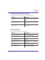
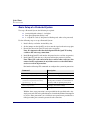
1
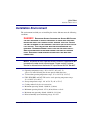
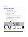
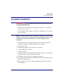
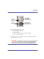
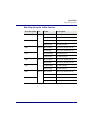
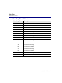
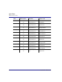
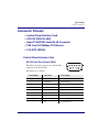
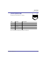
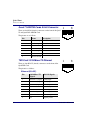
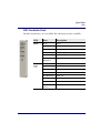
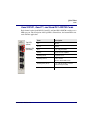
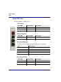
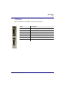
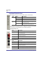
Axxius 800 QUICK START GUIDE Part Number: 002-0151-0006 Product Release: 2.2 May 2004 Copyright 2004 Carrier Access Corporation. All rights reserved. The information presented in this manual is subject to change without notice and does not represent a commitment on the part of Carrier Access Corporation. The hardware and software described herein are furnished under a license or non-disclosure agreement. The hardware, software, and manual may be used or copied only in accordance with the terms of this agreement. It is against the law to reproduce, transmit, transcribe, store in a retrieval system, or translate into any medium - electronic, mechanical, magnetic, optical, chemical, manual, or otherwise - any part of this manual or software supplied with the Axxius 800 for any purpose other than the purchaser’s personal use without the express written permission of Carrier Access Corporation. The Carrier Access Logo, Axxius, and NetworkValet are registered trademarks of Carrier Access Corporation. All other brand or product names are trademarks or registration trademarks of their respective companies or organizations. Contact Information: Carrier Access Corporation 5395 Pearl Parkway Boulder, CO 80301-2490 Corporate Phone: (800) 495-5455 Fax: (303) 443-5908 www.carrieraccess.com Customer Support Direct: (800) 786-9929 E-mail: [email protected] Supporting Software Version: Axxius 800 Controller Release 2.2 TSR Release 1.3 PREFACE Preface Safety Information CAUTION! ALWAYS USE CAUTION WHEN INSTALLING TELEPHONE LINES. READ THE CAUTIONS BELOW FOR DETAILS ON SAFETY GUIDELINES TO PREVENT INJURY. l Never touch uninsulated telephone wires and terminals unless the telephone line has been disconnected at the Network Interface (NI) as voltage potentials as high as 300 VAC may be present across the transmit and receive pairs. l Only use No. 26 AWG or larger telecommunication line cord, to reduce the risk of fire. l Never install telephone wiring during a lightning storm. l Never install telephone jacks in wet locations unless the jack is specifically designed for wet locations. l Refer to the installation section of this manual for a safe and proper installation procedure. All wiring external to this equipment should follow the current provision of the National Electrical Code. Preface Electrostatic Discharge (ESD) Precautions Electrostatic Discharge (ESD) Precautions ESD can damage processors, circuit cards, and other electronic components. Always observe the following precautions before installing a system component. 1. Do not remove a component from its protective packaging until ready to install it. 2. Wear a wrist grounding strap and attach it to a metal part of the system unit before handling components. If a wrist strap is not available, maintain contact with the system unit throughout any procedure requiring ESD protection. WARNING! INTEGRATED CIRCUITS (ICS) ARE EXTREMELY SUSCEPTIBLE TO ELECTROSTATIC DISCHARGE. UNLESS YOU ARE A QUALIFIED SERVICE TECHNICIAN WHO USES TOOLS AND TECHNIQUES THAT CONFORM TO ACCEPTED INDUSTRY PRACTICES, DO NOT HANDLE ICS. The ESD warning label appears on packages and storage bags that contain static-sensitive products and components. iv Axxius 800 - Release 2.2 QUICK START GUIDE In this Guide n Unpacking and Inspection n Installation Environment n Assembly of Axxius 800 n Rack Mounting n Compliant Installation n Chassis Connections n Connector Pinouts n LEDs n Provision a Unit Quick Start Unpacking and Inspection Unpacking and Inspection WARNING! OBSERVE PRECAUTIONS FOR HANDLING ELECTROSTATIC DEVICES. 1. Inspect containers for damage during shipment. Report any damage to the freight carrier for possible insurance claims. 2. Compare packing list with office records. Report any discrepancies to the office. 3. Open shipping containers, be careful not to damage contents. 4. Inspect contents and report any damage. 5. If equipment must be returned for any reason, carefully repack equipment in the original shipping container with original packing materials if possible. 6. If equipment is to be installed later, replace equipment in original shipping container and store in a safe place until ready to install. 8 Axxius 800 - Release 2.2 Quick Start Installation Environment Installation Environment The environment in which you are installing the Axxius 800 must meet the following conditions: DANGER! RESTRICTED ACCESS LOCATION FOR ACCESS 800: ACCESS CAN ONLY BE GAINED BY SERVICE PERSONNEL OR USERS WHO HAVE BEEN INSTRUCTED ABOUT THE POTENTIAL SAFETY HAZARDS THAT EXIST. ACCESS CAN ONLY BE GAINED TO THE EQUIPMENT LOCATION BY THE USE OF A TOOL OR LOCK AND KEY. TAKE PRECAUTIONS WHEN INSTALLING/SERVICING THE EQUIPMENT. HAZARDOUS ENERGY LEVELS EXIST ON THE POWER SUPPLY. BARE TELECOMMUNICATION NETWORK WIRING IS EXPOSED ON THE REAR PANEL. DISCONNECT FROM NETWORK BEFORE INSTALLING WIRE WRAP CONNECTIONS. NOTE: Installation of unit in Operator Access Locations is possible for 48V powered units under certain circumstances. Please contact Customer Service for information on the Axxius DC Input Shroud Kit P/N 790-0027. l Operating temperature range: -40° to 149° F (-40° to 65° C) *please see items following that do not operate within this range l V.34 modem operating temperature range: 32° to 149° F (0° to 65° C) l FXO, ISDN BRI, and OCU-DP service cards operating temperature range: 32° to 104° F (0° to 40° C) l Storage temperature range: -40° to 158° F (-40° to 70° C) l Cooling method is by free air convection l Maximum operating altitude: 10,000 ft. (3,048 m) l Minimum operating altitude: 197 ft. (60 m) below sea level l Maximum non-operating altitude: 40,000 ft. (12,192 m) l Relative humidity (non-condensing) range: 0 to 95% Axxius 800 - Release 2.2 9 Quick Start Assembly of Axxius 800 Assembly of Axxius 800 The cards should be positioned according to the following guidelines: l Power Supply(s) 24 or 48 VDC Single Power Supply - slot Power 1 or Power 2 Dual Power Supplies - slot Power 1 and Power 2 l Controller card(s) DS1 or DS3 Single Controller card - slot A1 or A2 Dual Controller cards - slot A1 and A2 l Interface card The Interface card is designed with two boards that follow a single guide. l Service Cards can be in any slot 1 through 8. Note: Cards that use the front cable connections should be loaded from Slot 8 to 1. This will minimize card access issues due to cable interference. l Relay Card in the Relay slot. l Always install blank faceplates in any unused slots. Future Development Power Supplies (P1 & P2) 10 Controller Cards (A1 & A2) Interface Card Service Card Slots 1-8 Relay Card Axxius 800 - Release 2.2 Quick Start Rack Mounting Rack Mounting The Axxius 800 can be mounted on a 19 or 23 inch rack with Carrier Access mounting brackets. NOTE: The Axxius 800 requires at least 3/4 inches of free air space above and below the chassis (approx 1/2 RU) for air circulation. Always leave at least 14" clearance in front of the unit, to add and remove cards. Axxius 800 mounted to a 19" rack with mounting brackets Bracket Ears to the front Bracket Ears to the back Axxius 800 - Release 2.2 Axxius Front Depending on the customer needs the mounting brackets can be mounted with fingers to the front or to the back of the unit 11 Quick Start Rack Mounting To maintain proper convection cooling, maintain at least 1/2 RU between the Axxius and any other equipment (each Axxius occupies 3 RU of rack space). Therefore, if one Axxius is mounted above another Axxius, then there would be a total of 1 RU between them (1/2 RU above the lower unit and 1/2 RU below the upper unit). Using the 1/2 RU airspace guideline, up to 15 Axxius 800 units may be installed in a 7’ equipment rack 1 } 2 1/2 RU free space 1/2 RU free space 1/2 RU free space 3 1/2 RU free space 4 5 6 7 8 9 Axxius = 2 RU Spacing = 1RU (1/2 above 1/2 below) 10 11 12 13 14 15 12 Axxius 800 - Release 2.2 Quick Start Compliant Installation Compliant Installation WARNING! USE MINIMUM ALL TELECOMMUNICATION NETWORK CONNECTIONS MUST 26 AWG WIRE. 1. Mount unit in an area that meets Environment conditions, see “Installation Environment” on page 3. 2. Unit should have power supply(s), controller(s) and Interface cards installed before power up. NOTE: All cards (power supplies, controllers, interface, relay and service) slide into the unit in the same manner. There are guides for each slot (top and bottom), which the card follows until it is firmly seated into the backplane. 3. Ground the system, secure the ground lugs to the terminals using the nuts provided. Attach #6 or #8 AWG copper wire to the terminal. 4. Install service cards. 5. Install blank faceplates in any slot that is not occupied. 6. Connect BITS Clock 1 and/or 2 7. Connect Alarming 8. Secure the power cable and the ground cable with a plastic tie (not included). Keep these cables separate from the signal cables. 9. Terminate each signal cable to its appropriate connector. 10. Secure the signal cables using the small holes along the bottom of the rack and plastic ties (not included). 11. Plug in power, to the system, apply the appropriate power for the installed Power Supply(s) Axxius 800 - Release 2.2 13 Quick Start Chassis Connections Chassis Connections The following illustrations show all connectors on the rear, as well as the front (interface card) of the Axxius 800. Visible Alarms Ground Terminals Slot 1-8 Wire Wrap Connectors Power Connectors A and B Clock A and B Audible Alarms External Alarm Inputs Back of the Axxius 800: l l l l l l l 14 Audible Alarms External Alarm Inputs Visible Alarms Input (power, P1 and P2) Bits Clock 1 and 2 Wire Wrap Connectors (slots 1-8) Ground Lugs Axxius 800 - Release 2.2 Quick Start Chassis Connections 10Base-T Ethernet RS-232 DS3 (SMB) Connectors (4) DS1 (RJ-48) Connectors (4) Front of the Axxius 800 - Interface Card l l l l 10Base-T Ethernet (RJ-48C) RS-232 Craft Port DS3-1 and 2 Transmit and Receive connectors (SMB) DS1 (1-4) connectors (RJ-48) For information on this card and all connectors see the Axxius 800 User Manual “Control Panel Interfaces” on page 11. CAUTION! THE AXXIUS 800 CONTAINS CIRCUIT CARDS AND COMPONENTS THAT ARE SUBJECT TO DAMAGE BY ELECTROSTATIC DISCHARGE (ESD). ALWAYS FOLLOW THE ELECTROSTATIC DISCHARGE (ESD) PRECAUTIONS. Axxius 800 - Release 2.2 15 Quick Start Chassis Connections Chassis Ground Connector Ground Terminals 1. Route wire (#6 or #8 AWG copper) from building ground to lug on Axxius 800. 2. Strip insulation off wire end, if necessary. Ground Lug Compression Screw Lug Barrel 3. Loosen compression screw until opening is large enough to accept ground wire. 4. Insert ground wire into lug barrel, beneath compression plate and tighten compression screw. 5. Attach ground lug to chassis 16 Axxius 800 - Release 2.2 Quick Start Chassis Connections Power Connections There are three power supplies available with the Axxius 800; 24 VDC and 48 VDC and 48 VDC NI, all use this connector. The Axxius 800 supports a redundant power system, therefore there is INPUT (power) P1 and P2. Input Power Power Supply Rated Amperage Recommended External Input Fuse 24 VDC 5 Amp 7 Amp 48 VDC/48 VDC NI 2.5 Amp 3.5 Amp A separate fuse should be used for each DC input NOTE: If two power supplies are installed into the system they MUST be of the same type (24 VDC, 48 VDC or 48 VDC NI). Wire each connector to a power source: 1. Ensure that no power is present on the two wires to be connected. DANGER! POSSIBLE SHOCK HAZARD EXISTS, PLEASE FOLLOW INSTRUCTIONS CAREFULLY. 2. Strip the two wires from the power source so that approximately 5/16 inch of bare wire is exposed. 16 or 18 AWG insulated copper wire is recommended for power connections. 3. Insert the Battery Return and DC wires into the appropriate square holes, one at a time. 4. Tighten screws to clamp wires. Axxius 800 - Release 2.2 17 Quick Start Chassis Connections 5. Ensure that no bare wire shows after the wires are installed. Provided Connector (male) Tighten screws to clamp wires Set Screw + - 6. Plug connector in the INPUT (power) connector, as seen in the graphic and secure with set screws. 7. Apply power to connector. 8. Verify with voltmeter that voltage is correct and polarity is correct. 9. Plug connector(s) into the Axxius 800. 10. A green light should appear on the DC Input LED on the front of the Power Supply. 18 Axxius 800 - Release 2.2 Quick Start Chassis Connections External Alarm Inputs The external alarm input connector supports 10 alarm inputs and is composed of two 10-pin connectors (two input pairs for each). External Alarm Input 1. Strip wire so that approximately 5/16 of bare wire is exposed. back of Axxius Connector plugged into Axxius Tighten screw to clamp wire Set screw Wire 2. Insert wire into opening and tighten screw to clamp wire. 3. Ensure that no bare wire shows after the wires are installed. 4. Plug connector in the EXTERNAL ALARMS INPUTS connector, as seen in the graphic above and secure with set screws. Axxius 800 - Release 2.2 19 Quick Start Chassis Connections Visible and Audible Alarms The external alarm connectors are six-pin connectors with two output pairs for each alarm level (pins 1 & 2 for minor, pins 3 & 4 for major and 5 & 6 for critical alarms). Visible Alarm Audible Alarm 1. Strip wire so that approximately 5/16 of bare wire is exposed. pin 1 back of Axxius Wire Connectors plugged into Axxius Set screw Tighten screw to clamp wire 2. Insert wire into opening and tighten screw to clamp wire. 3. Ensure that no bare wire shows after the wires are installed. 4. Plug connector in the AUDIBLE ALARMS or VISIBLE ALARMS connector, as seen in the graphic above and secure with set screws. 20 Axxius 800 - Release 2.2 Quick Start Chassis Connections BITS Clock 1/BITS Clock 2 The external alarm connectors are three-pin wire-wrap connectors. One for each, Tip (T), Ring (R) and Shield (S). Tip and Ring are the two connections for the 100 ohm differential signal to the box. Shield is for grounding the shield of the clock cable to the Axxius. If the customer is not using shielded cable, then only the Tip and Ring is connected. Bits Clock 1 and 2 back of Axxius Axxius 800 - Release 2.2 21 Quick Start Chassis Connections Slot (1-8) Wire Wrap Connectors The Axxius 800 provides wire wrap connectors for each slot (1-8) of the unit. Pinouts are clearly labeled with the pins. WARNING! DISCONNECT FROM NETWORK BEFORE INSTALLING WIRE WRAP CONNECTIONS. Wire Wrap Connectors 22 Axxius 800 - Release 2.2 Quick Start Chassis Connections Wire Wrap Pinout for 4 Wire Services Wire Wrap Pins T1 Name Description 1RX Port 1 Receive Ring Receive from DS1 network Receive Tip Receive from DS1 network Transmit Ring To DS1 network Transmit Tip To DS1 network Receive Ring Receive from DS1 network Receive Tip Receive from DS1 network Transmit Ring To DS1 network Transmit Tip To DS1 network Receive Ring Receive from DS1 network Receive Tip Receive from DS1 network Transmit Ring To DS1 network Transmit Tip To DS1 network Receive Ring Receive from DS1 network Receive Tip Receive from DS1 network Transmit Ring To DS1 network Transmit Tip To DS1 network 1TX 2RX Port 2 2TX 3RX Port 3 3TX 4RX 4TX Axxius 800 - Release 2.2 Port 4 23 Quick Start Chassis Connections Wire Wrap Pinout 2 Wire Services Wire Wrap Pins 24 Description T1 Channel 1 Transmit Tip R1 Channel 1 Transmit Ring T2 Channel 2 Transmit Tip R2 Channel 2 Transmit Ring T3 Channel 3 Transmit Tip R3 Channel 3 Transmit Ring T4 Channel 4 Transmit Tip R4 Channel 4 Transmit Ring T5 Channel 5 Transmit Tip R5 Channel 5 Transmit Ring T6 Channel 6 Transmit Tip R6 Channel 6 Transmit Ring T7 Channel 7 Transmit Tip R7 Channel 7 Transmit Ring T8 Channel 8 Transmit Tip R8 Channel 8 Transmit Ring Axxius 800 - Release 2.2 Quick Start Chassis Connections Standard Telco Color Code Circuit connections are made at the wire wrap connectors. The pinouts are as follows: Pair Pin Location Function Color Code 1 26 1 Tip Channel 1 Ring Channel 1 White/Blue Blue/White 2 27 2 Tip Channel 2 Ring Channel 2 White/Orange Orange/White 3 28 3 Tip Channel 3 Ring Channel 3 White/Green Green/White 4 29 4 Tip Channel 4 Ring Channel 4 White/Brown Brown/White 5 30 5 Tip Channel 5 Ring Channel 5 White/Slate Slate/White 6 31 6 Tip Channel 6 Ring Channel 6 Red/Blue Blue/Red 7 32 7 Tip Channel 7 Ring Channel 7 Red/Orange Orange/Red 8 33 8 Tip Channel 8 Ring Channel 8 Red/Green Green/Red 9 34 9 Tip Channel 9 Ring Channel 9 Red/Brown Brown/Red 10 35 10 Tip Channel 10 Ring Channel 10 Red/Slate Slate/Red 11 36 11 Tip Channel 11 Ring Channel 11 Black/Blue Blue/Black 12 37 12 Tip Channel 12 Ring Channel 12 Black/Orange Orange/Black 13 38 13 Tip Channel 13 Ring Channel 13 Black/Green Green/Black 14 39 14 Tip Channel 14 Ring Channel 14 Black/Brown Brown/Black Axxius 800 - Release 2.2 25 Quick Start Chassis Connections Pair 26 Pin Location Function Color Code 15 40 15 Tip Channel 15 Ring Channel 15 Black/Slate Slate/Black 16 41 16 Tip Channel 16 Ring Channel 16 Yellow/Blue Blue/Yellow 17 42 17 Tip Channel 17 Ring Channel 17 Yellow/Orange Orange/Yellow 18 43 18 Tip Channel 18 Ring Channel 18 Yellow/Green Green/Yellow 19 44 19 Tip Channel 19 Ring Channel 19 Yellow/Brown Brown/Yellow 20 45 20 Tip Channel 20 Ring Channel 20 Yellow/Slate Slate/Yellow 21 46 21 Tip Channel 21 Ring Channel 21 Violet/Blue Blue/Violet 22 47 22 Tip Channel 22 Ring Channel 22 Violet/Orange Orange/Violet 23 48 23 Tip Channel 23 Ring Channel 23 Violet/Green Green/Violet 24 49 24 Tip Channel 24 Ring Channel 24 Violet/Brown Brown/Violet 25 50 25 Not used/Spare at this time Violet/Slate Slate/Violet Axxius 800 - Release 2.2 Quick Start Connector Pinouts Connector Pinouts l Control Panel Interface Card l OCU-DP (DDS RJ-48S) l Quad T1/ADPCM Cards RJ-48 Connector l TSR Card 10/100Base-TX Ethernet l V.35 DCE (DB-26) Control Panel Interface Card RS-232 Craft Port (Female DB-9) 1 The RS-232 craft port connects via a female DB-9 connector on the Axxius 800. 5 6 9 The pinouts are as follows: Pin Number Direction Description 1 Outbound Carrier Detect 2 Outbound Receive Data 3 Inbound Transmit Data 4 Inbound Data Terminal Ready 5 Signal Ground 6 Outbound Data Set Ready 7 Inbound Request to Send 8 Outbound Clear to Send 9 n/c Not Connected Axxius 800 - Release 2.2 27 Quick Start Connector Pinouts DS1 Connection Ports 1 8 1 8 The DS1 connection ports are each equipped with a standard RJ-48C (female) on the Axxius 800 unit. The pinouts are as follows: DS1 (RJ-48C) Pin Name Description 1 Receive Ring Receive from DS1 network 2 Receive Tip Receive from DS1 network 3 N/C Not connected 4 Transmit Ring To DS1 network 5 Transmit Tip To DS1 network 6 -8 N/C Not connected 10/100Base-TX Ethernet The 10/100Base-TX Ethernet (female) port to connect to a remote management tool such as Telnet or an SNMP-based Network Management System. The pinouts are as follows: Ethernet (RJ-45) 28 Pin Name Description 1 Receive + Receive from network 2 Receive - Receive from network 3 Transmit + Transmit to network 4 N/C Not connected 5 N/C Not connected 6 Transmit - Transmit to network 7-8 N/C Not connected Axxius 800 - Release 2.2 Quick Start Connector Pinouts OCU-DP (DDS RJ-48S) The pinout for RJ-48S female is as follows: 1 Pin Function Description 1 Receives Data (R-1) From Customer to Network Interface 2 Receives Data (T-1) From Customer to Network Interface 3-6 Not Used 7 Transmits Data (T) From Network Interface to Customer 8 Transmits Data (R) From Network Interface to Customer 8 Note: The above listed functions are relative to this port. Axxius 800 - Release 2.2 29 Quick Start Connector Pinouts Quad T1/ADPCM Cards RJ-48 Connector There are four RJ-48 (female) connectors on the front of the Quad T1 and Quad DS1 ADPCM Card. 1 8 1 8 The pinouts are as follows: Pin Name Description 1 Receive Ring Receive from DS1 network 2 Receive Tip Receive from DS1 network 3 n/c Not connected 4 Transmit Ring To DS1 network 5 Transmit Tip To DS1 network 6-7 n/c Not connected 8 Chassis Ground TSR Card 10/100Base-TX Ethernet There are four RJ-45C (female) connectors on the front of the Quad TSR Card. The pinout is as follows: Ethernet (RJ-45C) 30 Pin 10/100Base-TX Signals RS-232 Signals 1 Transmit + (output) CTS (input) 2 Transmit - (output) RTS (input) 3 Receive + (input) DSR (input) 4 n/c TXD (output) 5 n/c RXD (input) 6 Receive - (input) DCD (input) 7 n/c DTR (output) 8 n/c Signal ground Axxius 800 - Release 2.2 Quick Start Connector Pinouts V.35 DCE (DB-26) The V.35 DCE data port connection is made at the sub-miniature DB-26 connector on the Axxius 800 using the 10-foot, 25-foot, or 50 foot Carrier Access DTE V.35 cable equipped with a sub-miniature DB-26 connector and a 34-pin Winchester connector. This cable is used to connect the Axxius 800 V.35 DCE data ports to synchronous V.35 DTE data sources up to 1.536 Mbps, all rates (1-24) Nx56 or Nx64 channel-rate progression. The Carrier Access Corporation V.35 data cables are built according to the pin assignments listed below: Sub-miniature DB-26 Signal 1 (+ Shield) 7 2 14 3 16 4 20 5 6 12 8 11 24 10 23 15 17 22 25 9, 13, 18 Protective Ground → Signal Ground → ← Transmit Data A ← Transmit Data B Receive Data A → Receive Data B → ← RTS ← DTR CTS → DSR → Test Mode → CD (RLSD) → ← External Clock A ← External Clock B Xmit Clock A → Xmit Clock B → Receive Clock A → Receive Clock B → ← Local Loopback ← Remote Loopback Open Pins/No Contact 19, 21, 26 Open Pins/No Contact Axxius 800 - Release 2.2 ← ← Winchester 34-pin (female) Paired Signals A B P S R T C H D E K F U W Y AA V X J BB L, N, NN 31 Quick Start LEDs LEDs This section provides details about the LEDs on the Axxius 800. 32 l Control Panel LEDs l DS1 Controller Card l DS3 Controller Card l 24VDC and 48VDC Power Supplies l FXO Card l ISDN BRI Cards l OCU-DP Card l POTS Cards l Quad T1/DS1 ADPCM Cards l Quad TSR Card l V.35 Card l Low Speed Protection Card Axxius 800 - Release 2.2 Quick Start LEDs Control Panel LEDs Alarm LEDs LED State Description CRITICAL Off No critical alarms present Red Critical alarms present Off No major alarms present Red Major alarm present Off No minor alarms present Red Minor alarms present Off Normal mode. No alarms are being suppressed. Red Alarm cutoff active. One or more active alarms suppressed. MAJOR MINOR ACO Axxius 800 - Release 2.2 33 Quick Start LEDs Ethernet LEDs LED State Description STATUS Off Link Down Green Link Up Flashing Green Traffic on Link When Status LED is on or flashing: 34 LED State Description 10/100 Off Link is 10 Mb Green Link is 100 Mb Axxius 800 - Release 2.2 Quick Start LEDs DS1 Controller Card The DS1 Controller has a set of six LEDs. The table below describes each LED. LED State Description STAT Green Active Red Failed Flashing Red System Reset Yellow Hot Standby Flashing Yellow Cold Standby Alternating Red/Yellow Application Loading Off Port Shutdown Green Good Line Slow Blink Green Loopback Red LOS Slow Blink Red LOF, AIS Fast Blink Red Card Failure Yellow Code Violation Slow Blink Yellow RAI LINE STAT (1-4) Axxius 800 - Release 2.2 35 Quick Start LEDs DS3 Controller Card The DS3 Controller has a set of six LEDs. The table below describes each LED. LED State Description STAT Green Active Red Failed Flashing Red System Reset Yellow Hot Standby Flashing Yellow Cold Standby Alternating Red/Yellow Application Loading Off NO transport or port shutdown Green Good Line Slow Blink Green Loopback Red LOS Slow Blink Red LOF, AIS Fast Blink Red Card Failure Yellow Standby, when path protection is active Slow Blink Yellow RAI, IDLE, or if protection is active Out-of-Service LINE STAT (1-4) 36 Axxius 800 - Release 2.2 Quick Start LEDs 24VDC and 48VDC Power Supplies Both power supply cards have identical LEDs, as described in the table below. LED State Description DC Input Off DC input missing or fuse blown Yellow Under or over-voltage Green Valid DC input present Off No 5V output (neither power supply operating) Red 5V output not functioning (2nd unit operating) Green 5V output good Output Voltage Status Axxius 800 - Release 2.2 37 Quick Start LEDs FXO Card Each FXO port on a card has its own LED, described in the table below. State Loop Start Meaning Ground Start Meaning Dial Pulse Termination Meaning Off N/A Idle (tip open) Idle (loop open) Green Idle Tip ground (incoming seizure) Incoming seizure Red N/A Ring ground (outgoing seizure) Loop closure (outgoing seizure) Yellow Call in progress Call in progress Call in progress (reverse battery) Flashing green Ringing Ringing N/A ISDN BRI Cards Each ISDN BRI on a card has its own LED, described on the table below. 38 State Description Off Line U-interface is attempting synchronization, or BRI is out of service. Red Line alarm (LOS or self test failure) Yellow ES or SES has occurred. Flashing yellow Line U-interface is synchronized with customer equipment, but is not passing customer data. Flashing green Line U-interface is in external loopback toward the switch at the unit. Green Normal (Line U-interface is active and transparently passing customer data.) Axxius 800 - Release 2.2 Quick Start LEDs OCU-DP Card There are two LEDs for each channel on the OCU-DP card. The function for each LED is listed below: State LED Description Yellow Flickering ALL Boot Software in control. Green (walking down) Red (walking up) ALL Application Software in control (repeated 3.5 times). Red, slow flash ALL In Boot. Application flash code checksums did not match and Boot is waiting for application download. Red ALL In Application code waiting for Controller to issue SW/HW revision request. This is the first request that comes from the OCU-DP card manager in the Controller. Green Yellow Top Bottom Port in Self-test. Duration is 5-8 seconds. Off Top Bottom Port is set down (Out-Of-Service). Green Top Port is receiving valid signals. Red Top Port is receiving no signal (primary) or no frame sync (secondary or clear channel). Red Flashing Bottom Port is receiving bipolar violations Yellow Bottom Port is in loopback. Axxius 800 - Release 2.2 39 Quick Start LEDs Single Channel POTS Cards The POTs channel LED (left) status is described in the table below. State Loop Start Meaning Off Calling Party Disconnect Green Idle Red N/A Yellow Call in progress Flashing green Ringing The second LED (right) is a status LED for the MODEM. 40 State Loop Start Meaning Off Calling Party Disconnect Green Ringing Yellow Carrier Detect Axxius 800 - Release 2.2 Quick Start LEDs Quad DS1/E1, Quad T1, and Quad DS1 ADPCM Cards Each channel on the Quad DS1/E1, Quad T1 and Quad DS1 ADPCM cards have two LEDs per port. The description of the top LED is shown below, the bottom LED is not used with this application. Top LED (active) Bottom LED (not used) Axxius 800 - Release 2.2 State Description Off Off line Green Normal Red Loss of Signal (LOS) Yellow Bipolar Violation (BPV) Flashing Green Loopback active Flashing Yellow Yellow Alarm (Remote Alarm Indication) Flashing Red (Slow) Loss of Frame (LOF) or Alarm Indication Signal (AIS) Flashing Red (Fast) Self-test Failure 41 Quick Start LEDs Quad TSR Card The Quad TSR has 2 LEDs per port. At Power-up TOP LED Bottom LED Description Off Off Loss of power Red Red Card is inoperative Flashing Red Flashing Red Self-test or Boot in-process TOP LED Bottom LED Description Green Solid (Link) Green Solid (Link) Port set for Ethernet - see below Flashing Red Flashing Red Self-test or Boot in-process Normal Operation Port Set for Ethernet Top LED indicates 100M Link, Bottom LED indicates 10M Link State Description Off No Ethernet link Green Link but no activity Red Flashing Current Ethernet collision Green Flashing Current Ethernet receive Yellow Flashing Current Ethernet transmit Port Set for RS-232 42 TOP LED Bottom LED Description Yellow Flashing Yellow Current transmit Yellow Flashing Green Current receive Yellow Off No Activity Axxius 800 - Release 2.2 Quick Start LEDs V.35 Card Each V.35 port has its own LED, as shown in the table below. State Description Off No T1 Assignment Green Normal (CD/RTS) Active Red CD inactive (T1-side failure) Yellow RTS inactive (equipment-side failure) Flashing Yellow Loopback toward T1 or equipment loop test Flashing Green Loopback toward equipment or network loop test Axxius 800 - Release 2.2 43 Quick Start LEDs Low Speed Protection Card The Low Speed Protection card has 10 LEDs, which are defined below. LED State Description STAT Green Enabled Red Disabled Flashing Green Disabled Off The corresponding slot is not being protected via the Protection card. Yellow One or more ports of the corresponding slot are being protected via the Protection card. Slot Status (1-8) Each channel on the Quad T1 card has two LEDs. The description of the top LED is shown below, the bottom LED is not used with this application. Quad T1 Backup Card State Description Off Not set up as Backup Green Port is switched to protection mode (the port it is protecting will be flashing green) Red Displays red on backup card after other T1 port in same line is set up to be protected Flashing Green Port is set up and ready to grant backup when needed Flashing Yellow Port is booting up to be backup card Quad T1 Protected Card 44 State Description Off Not set up as Backup Green Protected port is healthy and not in protected mode Red Displays red on backup card after other T1 port in same line is set up to be protected Flashing Green Port has failed and the Backup card has granted protection Flashing Yellow Port is booting up to be backup card Axxius 800 - Release 2.2 Quick Start Provision a Unit Provision a Unit l Local using CLI, Telnet, Modem or SNMP (Valet) l Remotely over an in-band DS0 l Remotely over an SNMP network using NetworkValet EMS Command Line Interface (CLI) You can access the CLI using either of the following methods: l RS-232 connected to the DB-9 port. l Telnet via Ethernet (10Base-T) l Modem Setting up a CLI connection To connect to the CLI via the RS-232 port, set up a connection to a PC serial port or dumb terminal using Hyperterm, ProComm, or similar terminal emulation software: l Set the Port Settings to: Bits per second: 9600 Data bits: 8 Parity: None Stop bits: 1 Flow control: None l Set the Terminal Emulation to: VT100 NOTE: The Default IP address of the Axxius 800 Controller is 10.0.0.10. Axxius 800 - Release 2.2 45 Quick Start Provision a Unit Basic System Setup Initial Setup Use the following commands for your initial setup, for further information see the specific command listed in Chapter 5, CLI Commands. 46 Command Description set date dd/mm/yyyy Set the system date, using the format day/month/year. See the set date command for details. set time {hh:mm:ss} Set the system time. See the set time command for details. set id {“id-name”} Set the systemID name. Remember to enclose this name in quotes. See the set id command for details. set clock {nonrevertive| revertive|switch} Set the signal clock switching. See the set clock command for details. set {clock1|clock2} {source} Set the primary and secondary clock source. See the set clock (1 and 2) command for details. set ethernet ip address {ip-addr} [mask] Set the Ethernet IP address and optionally the subnet mask, for the Axxius 800. See the set ethernet ip address command for details. set ip gateway {ip-addr} Set the IP gateway for the Axxius 800. See the set ip gateway command for details. clear log Initialize the event log. See the clear key command for details. status equipment [slot] See the status of the equipment. See the status equipment command for details. Axxius 800 - Release 2.2 Quick Start Provision a Unit Set Up Security Use the following commands to set up the security on the Axxius 800. Command Description set user {"user-name"} level {1-3} Specify the user name and the security level. See set user command for details. set user {"user-name"} password Set a password for the user. See set user command for details. Set Up a DS0/Channel Use the following commands to set up a DS0. Command Description set {ds0-addr} type {data|voice} Set the channel type. See set (ds0) command for details. set {ds0-addr} signal {ls|gs|emw|emdw|emi|emicpd} Set the signaling option for the channel. See set (ds0) command for details. Axxius 800 - Release 2.2 47 Quick Start Provision a Unit Set Up a DS1/T1 Use the following commands to set up a DS1. See the set (ds1) command for more details. 48 Command Description set {ds1-addr} up Activate the port. set {ds1-addr} fdl {none|t1403} Set the Facilities Data Link (FDL) capabilities. set {ds1-addr} framing {d4| esf} Set the framing option for the DS1. set {ds1-addr} id {"id-name"} Set the circuit identification name for the DS1. set {ds1-addr} lbo {1-8} Set the line buildout value for the DS1. set {ds1-addr} linecode {ami|b8zs} Set the linecode for the DS1. set {ds1-addr} loopdetect {on|off} Set the detection/reaction to CSU loopcodes. set {ds1-addr} threshold {day|min15} {bes|css|dm|es |lcv|les|pcv|sefs|ses|uas) Set default thresholds for the DS1. Axxius 800 - Release 2.2 Quick Start Provision a Unit Set Up a DS3 Use the following commands for DS3 setup. See the set (ds3) command for more details. Command Description set {ds3-addr} up Activate the port. set {ds3-addr} id {"id-name"} Set the DS3 ID. set {ds3-addr} clock {loop|normal} Set the transmit clock source. set {ds3-addr} berthreshold {value} Set the Bit Error Rate protection switchover threshold. set {ds3-addr} dejitter {off|on} Set the De-jitter buffer on or off. set {ds3-addr} equipment id {"string"} Set the DS3 equipment PMDL ID string. set {ds3-addr} facility id {"string"} Set the DS3 facility PMDL ID string. set {ds3-addr} frame {"string"} Set the DS3 frame PMDL ID string. set {ds3-addr} framing {cbit|m23} Set the framing option for the DS3. set {ds3-addr} location id {"string"} Set the DS3 location PMDL ID string. set {ds3-addr} portnum {"string"} Set the DS3 port number PMDL string. set {ds3-addr} gennum {"string"} Set DS3 generation number PMDL string. set {ds3-addr} loopdetect {off|on} Set the detection/reaction to CSU loopcodes. set {ds3-addr} protect {off|on} Set port protection on the DS3. set {ds3-addr} reversion {off|on} Set protection reversion on the DS3. set {ds1-addr} threshold {day|min15} {ccv|ces|cses|lcv |les|pcv|pes|pses|sefs|uas) Set default thresholds for a DS3. set {ds3-addr} unit {"string"} Set the DS3 unit code PMDL string. Axxius 800 - Release 2.2 49 Quick Start Provision a Unit Setup DS1 ADPCM Before configuring the DS1 ADPCM card, there are some basics that need to be considered: l All DS0s to be compressed reside on T1 number 1 of the ADPCM card l ADPCM is capable of transporting any combination of 64 and 32K l All 24 DS0s can be transported either compressed or uncompressed, but not both at the same time. l All DS0s to be compressed must be set to type data. The following is a basic setup: Command Description Connect T1 cable to port 1 of the ADPCM service card 50 set {adpcm_card-addr} {none|map1|map2|map3} Enable compressing by selecting Map type. Note: none disables compression. See the following section on Maps. show (adpcm_card-addr} Displays the status of the card, and the mapping. set {2:1:1-12} type data Set the channel (DS0) type to data on the ADPCM channels. See set (ds0) command for more information. set {2:4:1-12} type data Set the channel (DS0) type to data on the channels for cross-connect. See set (ds0) command for more information. connect 2:1:1-12 2:4:1-12 Set cross-connects. The example connects all 24 channels of the ADPCM to the 12 channels of the T1 (now compressed) on port 4. Example is with map2 show connect adpcm {2:1} Displays the connections made above. Axxius 800 - Release 2.2 Quick Start Provision a Unit Establish a Static Channel Connection Use the following commands to establish a static channel connection. Command Description set {ds0-addr} type {voice|data} Set the channel type for the channel you want to map. See set (ds0) command for details. set {ds0-addr} signal {emdw| emi|emicpd|emw|gs|ls} Set the signaling option for the channel you want to map. See set (ds0) command for details. connect {slot:port} {slot:port} Connect the channels. See the show connect command for details. Set Up a V.35 Port Use the following commands to set up a V.35 port. Command Description set {v35-addr} cts {cd|high|low|rts} Set the Clear to Send operation mode. See set (v35) command for details. set {v35-addr} data {invert|normal} Set the data mode. See set (v35) command for details. set {v35-addr} clock {source|external} Set the clock mode. See set (v35) command for details. set {v35-addr} speed {56K|64K} Set the speed. See set (v35) command for details. set {v35-addr} txclkinv {invert|normal} Set the transmit clock inversion mode. See set (v35) command for details. set {v35-addr} rxclkinv {invert|normal} Set the receive clock inversion mode. See set (v35) command for details. Axxius 800 - Release 2.2 51 Quick Start Provision a Unit Set Up a Single Channel POTS card Use the following commands to set up a POTS card. Command Description set {fxsPS-addr|fxsPSM-addr} {ls|lsrb} Set the signaling option for the port. See the set (fxsPS or fxsPSM) command for details. set {fxsPS-addr|fxsPSM-addr} rxgain {n} Set the receive gain/loss in dB. See the set (fxsPS or fxsPSM) command for details. set {fxsPS-addr|fxsPSM-addr} txgain {n} Set the transmit gain/loss in dB. See the set (fxsPS or fxsPSM) command for details. Change the IP Address of the DS0 Management Channel Use the following commands to change the IP over DS0 Management Channel for the Axxius 800. Command Description set ipds0 down Set the DS0 management channel down set ipds0 ip address {ip-addr} Set the DS0 management channel IP address. set ipds0 up Set the DS0 management channel up. Set Up IP Addresses for Telnet CLI Use the following commands to setup Telnet addresses for the Command Line Interface (CLI). 52 Command Description set ethernet ip address {ip-addr} {mask} Set the Ethernet IP address, in the IP address format. See the set ethernet ip address command for more details. set ip gateway {ip-addr} Set the IP gateway, in the conventional IP address format. See the set ip gateway command for more details. Axxius 800 - Release 2.2 Quick Start Provision a Unit Upgrade the Axxius 800 Software Use the following commands to determine the Controller software level, then upgrade the software to the latest version. Command Description status equipment Determine the software level. See the status equipment command for more information. load tftp {ip-addr} {"filename"} (or load xmodem) Load the new software to the Axxius 800. See the load tftp and load xmodem command for more information. Axxius 800 - Release 2.2 53 Quick Start Provision a Unit Basic Setup of a Protected System To set up a Protected System, the following is required: l l l Axxius 800 with software 1.2 or higher Low Speed Protection (Relay) card 2 - 6 Quad T1 Cards (1 designated as Backup card, others to be protected) Use the following steps to set up a Protected System. 1. Install a Relay card in the Axxius Relay slot. 2. Set the jumpers on the Quad T1 cards to route the signal to the wire wrap pins. 3. Prewire the chassis for Quad T1 cards (wire wrap pins). Note: It is imperative that the slot designated for the Quad T1 backup card have NO wire wrap connections. 4. Install Backup Quad T1 card into the designated service card slot (no prewire). 5. Install Quad T1 cards that are to be protected into the prewired card slots. Note: These QT1 cards can be in any slot, as well as other card types. Also removal and/or replacement of any of these service cards will not effect service to cards in adjacent slots. Perform the following CLI commands to configure the system for protection. Command Description set lsbackup {t1_card-addr} Defines the backup slot (can be any slot) set lsprotect enable To enable the Low Speed Protection option set lsprotect {slot:port} {revertive|nonrevertive} [priority] [1-7] This command defines the protected cards. Set all ports to revertive or non-revertive as necessary with an optional priority level show lsprotect To display the current settings status lsprotect To display the current status With the above steps protection is now provided for the specified cards. Any single protected card can be pulled from its slot with only minimal interruption to service. Since protection is on a 1xN basis once protection is provided for a failed port other ports cannot be protected at the same time. 54 Axxius 800 - Release 2.2