1
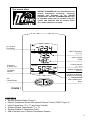
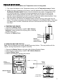
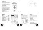
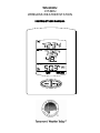
WS-9029U
915 MHz
WIRELESS WEATHER STATION
INSTRUCTION MANUAL
CONTENTS
03
03
04
05
06
06
08
09
10
10
10
introduction
features
quick set up guide
detailed set up guide
function keys
operations
mounting
troubleshooting
maintenance and care
specifications
warranty information
2
This product offers:
INSTANT TRANSMISSION is the state-of-the-art new
wireless transmission technology, exclusively
designed and developed by LA CROSSE
TECHNOLOGY. INSTANT TRANSMISSION offers you
an immediate update (every 4 seconds!) of all your
outdoor data measured from the sensors: follow
your climatic variations in real-time!
12 or 24 Hour
Time Display
Indoor Temperature
(°F or °C)
Indoor Humidity
(%RH)
Channel Indicator
(1, 2, or 3)
Connection
w/ Sensor Icon
Low Battery
Indicator
Outdoor Temperature
(°F or °C)
Minimum or Maximum
Temperature & Humidity
Set/
Channel Button
Minimum/Maximum/+
Button
FIGURE 1
FEATURES
• Wireless Weather Station (Figure 1).
• Remote Temperature Sensor with optional Channel 2 Probe (TX25U, Figure 2).
• Indoor Temperature (°F or °C) and Indoor Humidity.
• Wireless Outdoor Temperature (°F or °C).
• Optional Channel 2 Temperature Probe.
• Able to Receive up to 3 Remote Temperature Sensors.
3
•
Wall Hanging or Free Standing.
Remote
Temperature Sensor
LCD Temperature Display
Optional Probe
w/ 6 Foot Wire
FIGURE 2
Wall-Mounting
Bracket
ADDITIONAL EQUIPMENT (not included)
1. Two fresh AA 1.5V alkaline batteries for the wireless weather station.
2. Two fresh AAA 1.5V alkaline batteries for the remote temperature sensor.
3. One, Philips screwdriver for mounting.
QUICK SETUP
Hint: Use good quality Alkaline Batteries; avoid rechargeable batteries.
1. Have the Wireless Weather Station and Temperature sensor 3 to 5 feet apart.
2. Batteries should be out of both units for 10 minutes.
3. Place the batteries into the Temperature sensor first and next into the Wireless Weather
Station.
4. DO NOT PRESS ANY BUTTONS FOR 15 MINUTES.
In this time the Wireless Weather Station and the temperature sensor will begin to communicate with
each other, and the display will show both the indoor temperature and an outdoor temperature. If the
Wireless Weather Station does not display both temperatures after the 15 minutes, please retry the
set up as stated above. After both indoor and outdoor temperatures are displayed for 15 minutes you
can place your temperature sensor outdoors, and set your time.
The temperature sensor should be placed in a dry, shaded area (ex: under the eve of a roof). The
temperature sensor has a range of 330 feet. Any walls that the signal will have to pass through will
reduce distance. An outdoor wall or window will have up to 20 feet of resistance and an interior wall
will have up to 10 feet of resistance. Your distance plus resistance should not exceed 330 feet in a
straight line.
NOTE: Fog and mist will not harm your temperature sensor, but direct rain must be avoided.
4
DETAILED SETUP GUIDE
I. BATTERY INSTALLATION (When one Temperature sensor is being used)
1. First, insert the batteries to the Temperature sensor (see “A. Temperature sensor” below).
2. Within 2 minutes of powering up the sensor, insert the batteries to the Weather Station (see
“B. Wireless Weather station” below). Once the batteries are in place, all segments of the
LCD will light up briefly. Following the indoor temperature and the time as 12:00 will be
displayed, and the signal reception icon will flash. If they are not shown in LCD after 60
seconds, remove the batteries and wait for at least 60 seconds before reinserting them. Once
the indoor data is displayed user may proceed to the next step.
3.
After the batteries are inserted, the Weather Station will start receiving data signal from the
sensor. The outdoor temperature should then be displayed on the Weather Station. If this does
not happen after 2 minutes, the batteries will need to be removed from both units and reset
from step 1.
A. TEMPERATURE SENSOR
1. Remove the Battery Cover.
2. Observing the correct polarity, install 2 “AAA” Alkaline
Batteries—make sure they do not spring free, or start-up
problems may occur.
3.Replace the Battery Cover.
Battery
Cover
Battery
Compartment
Remote
Temperature
Sensor (TX-25U)
B. WIRELESS WEATHER STATION
Note: After the batteries are installed, DO NOT press any buttons. This may interfere with the
signals, causing temperatures to register incorrectly.
1. Remove the Battery Cover on the back of the Wireless Weather Station.
2. Observing the correct polarity, install 2 “AA” Alkaline Batteries.
3. Replace Battery Cover.
4. Wait 15 minutes before pressing any buttons.
Battery
Compartment
Battery
Cover
Wireless Weather
Station
Sensor signal
reception icon*
5
* When the signal is successfully received by the Weather Station, the icon will be switched on. (If not
successful, the icon will not be shown in LCD) So the user can easily see whether the last reception
was successful (icon on) or not (icon off). On the other hand, the short blinking of the icon shows that
a reception is being done now.
FUNCTION KEYS
The simple design of this product features 2 keys.
SET/CH:
• Press and hold for 5 seconds to enter set-up mode.
• Press and release to toggle between channels.
MIN/MAX/+:
• Press and release to toggle between minimum, maximum, and current temperature values.
• Press and hold 5 seconds to reset all minimum and maximum recorded values.
• Press and release to advance hours and minutes.
• Press and release to toggle between 12 hour time and 24 hour time.
OPERATIONS
12 OR 24 HOUR TIME SETTING
1. Press and hold the SET/CH button for 5 seconds.
2. “12h” will flash in the Time section of the LCD.
3. Press and release the MIN/MAX/+ button to toggle between 12 hour time and 24 hour time.
4. Press and release the SET/CH button to confirm selection and advance to the time setting.
Note: Selecting 12 hour time will automatically select Fahrenheit (°F) temperature. Selecting 24
hour time will automatically select Celsius (°C) temperature.
TIME SETTING
1. Press and hold the SET button for 5 seconds.
2. “12h” or “24h” will appear flashing in the TIME section of the LCD.
3. Press and release the SET/CH button once.
4. The hour will begin flashing.
5. Press and release the MIN/MAX/+ button to advance the hours.
6. Press and release the SET/CH button once more, and the minutes will begin to flash.
7. Press and release the MIN/MAX/+ button to advance the minutes.
8. Press and release the SET/CH button to confirm selection.
Note: When in the 12-hour format “PM.” will appear to the left of the hour in the time LCD between
the hours of noon and midnight.
OUTDOOR TEMPERATURE
The temperature received from the remote temperature sensor is viewed in the OUTDOOR LCD.
When there is more than one remote temperature sensor unit in operation, a “boxed” number will
appear to the right of the temperature. This indicates which remote temperature sensor unit (1, 2, or
3) is currently displaying its data in the OUTDOOR LCD. (This feature is explained in further detail in
the section—Adding Remote Temperature Sensors).
VIEWING MINIMUM AND MAXIMUM TEMPERATURE RECORDS
The WS-9029U keeps a record of the MINIMUM and MAXIMUM indoor and outdoor temperatures.
6
To view minimum and maximum temperatures: press the min/max/+ button once. “MIN” appears in
the bottom left of the LCD. The indoor and outdoor temperatures displayed when “MIN” appears are
the minimum recorded values. The minimum records will display for 30 seconds before returning to
the normal display mode.
Press the min/max/+ button again (once while “MIN” is still displayed, twice otherwise). “MAX”
appears in the bottom right of the LCD. The indoor and outdoor temperatures displayed when “MAX”
appears are the maximum recorded values. The maximum records will display for 30 seconds before
returning to the normal display mode.
While “MAX” is still displayed press the min/max/+ button again to return to the current data display.
Or you can wait 30 seconds, during either the minimum or the maximum readings, and the unit will
automatically return to current data readings.
RESETTING THE MIMIMUM AND MAXIMUM RECORDS
All the minimum and maximum records (minimum and maximum) will be reset after the min/max/+
button is pressed and held for 5 seconds.
OPTIONAL CHANNEL 2 TEMPERATURE PROBE
When the temperature probe is connected to the remote temperature sensor, the WS-9029U’s
channel 1 will display the remote temperature sensor data, and channel 2 will display the temperature
probe data. The remote temperature sensor data will always be displayed on the channel 1 and the
temperature probe on the channel 2.
If the probe on remote temperature sensor is unplugged, the "probe channel" on WS-9029U LCD will
show "---", the remote temperature sensor displayed value will still be shown.
The probe can be connected to the remote temperature sensor anytime. There is no need to reset the
units. The Weather Station will automatically detect the temperature probe and will display the
temperature probe data in channel 2.
ADDING TEMPERATURE SENSORS (OPTIONAL)
The WS-9029U is able to receive signals from 2 remote temperature sensors (TX-25U). These extra
sensors can be purchased through the same dealer as this unit
A. SET-UP OF MULTIPLE SENSORS
1. Remove all the batteries from the receiver and sensor(s) and wait 60 seconds. During these
60 seconds, press any button 20 times to discharge any excess power.
2. Insert the batteries to the first sensor.
3. Within 2 minutes of powering up the first sensor (Temperature sensor with probe), insert the
batteries to the Weather Station. Once the batteries are in place, all segments of the LCD will
light up briefly. Following the indoor temperature/humidity and the time as 12:00 will be
displayed, and the signal reception icon will flash. If they are not shown in LCD after 60
seconds, remove the batteries and wait for at least 60 seconds before reinserting them.
4. The outdoor temperature from the first sensor (channel 1) should then be displayed on the
Weather station. If this does not happen after 2 minutes, the batteries will need to be removed
from both units and reset from step 1.
5. If the temperature probe has been used, the outdoor temperature from channel 2 will then be
displayed. Otherwise, the outdoor temperature will display “---“.
Note: The temperature probe from the first sensor will always occupy “channel 2”. Channel 2 can
only be used for the temperature probe. If you choose not to use the temperature probe, Channel
2 will display “---“.
6. Insert the batteries to the second sensor as soon as the outdoor temperature readings from
the first sensor are displayed on the Weather station.
7
NOTE: You must insert the batteries into the second sensor within 30 seconds of
reception of the first sensor.
7. The outdoor temperature from the second sensor and the "channel 3" icon should then be
displayed on the Weather station. If this does not happen after 2 minute, the batteries will need
to be removed from all the units and reset from step 1.
Note: only the readings from the internal sensor of the second sensor will be displayed in “channel 3”
IMPORTANT: Transmission problems will arise if the setting for additional sensors is not
followed as described above. Should transmission problems occur, it is necessary to
remove the batteries from all units and start again the set-up from step 1.
B. VIEWING AND OPERATING WITH MULTIPLE TEMPERATURE SENSOR UNITS
1. To view the temperature of a different remote temperature sensor unit, press and release the
SET/CH button. A shift from one “boxed” number to the next should be observed in the
OUTDOOR LCD.
2. To determine which remote temperature sensor reading is displayed on the 3 channels, match the
temperature displayed on each channel, with the corresponding temperature displayed on the
LCD of each remote temperature sensor.
3. To view the Minimum/Maximum temperature: first select which remote temperature sensor to read
data from (indicated by the “boxed” number), then press the SET/CH button. Pressing this button
once will display the minimum temperature, and the date and time the data was recorded.
Pressing this button a second time (while “MIN” is still displayed, otherwise press the button twice)
will display the same data for the maximum recordings.
4. To reset the Minimum/Maximum readings, press and hold the MIN/MAX/+ button for 5 seconds,
this will reset all the minimum and maximum data from all sensors.
MOUNTING
THE REMOTE TEMPERATURE SENSOR
1. Remove the mounting bracket/stand from the temperature sensor.
2. Place the mounting bracket over the desired location.
3. The mounting bracket can attach to the sensor in the middle of the back or on the bottom.
4. Through the 3 screw holes of the bracket, mark the mounting surface with a pencil.
5. Screw mounting bracket onto the mounting surface. Ensure that the screws are flush with the
bracket.
6. Insert the remote temperature sensor into the bracket.
Back middle of
sensor inserted into
Mounting Bracket
Bottom of sensor
inserted into Mounting
Bracket
8
THE WIRELESS WEATHER STATION
The wireless weather station can be mounted in 2 ways:
• with the table stand or,
• on the wall with the use of a wall hanging screw (not included).
A. USING THE TABLE STAND
The wireless weather station comes with the table stand attached. If
you wish to use the table-stand all that is required is to pull out the table
stand on the back of the receiver and place the receiver on a flat
surface.
B. WALL MOUNTING
1. Make sure the table stand is flush against the wireless weather
station.
2. Fix a screw (not included) into the desired wall, leaving
approximately 1/4 of an inch (5mm) extended from the wall.
3. Place the wireless weather station onto the screw using the hanging
hole on the backside.
4. Gently pull the wireless weather station down to lock the screw into
place.
TROUBLESHOOTING
NOTE: For problems not solved, please contact La Crosse Technology.
Problem: Hour is incorrect (minute and date are correct)
Solution: Be sure correct time zone and daylight saving time settings are selected.
Problem: The LCD is faint
Solution: 1) Set the LCD contrast to a higher number
2) Replace batteries
Problem: No outdoor temperature is displayed.
Solution: 1) Remove all batteries, reinsert into sensor first, then into the wireless weather station.
2) Place remote temperature sensor closer to wireless weather station.
3) Be sure all batteries are fresh.
4) Place remoter temperature sensor and wireless weather station in position so the straight-line
signal is not passing through more than 2 or 3 walls.
Problem: Temperatures do not match if units are placed next to each other.
Solution: Each remote temperature sensor is manufactured to be accurate to within 1 degree plus or
minus and under normal conditions, so two sensors could be as much as 2 degrees different.
However, the difference can be exaggerated further because the sensors are designed for
different working environments. The indoor sensor is less responsive to ambient air currents
because of the shielding effect of the display's case. In addition, the case can act as a heat
sink to absorb and store heat from external sources (i.e. handling of the case or radiant heat).
Also, the much greater range of the remote temperature sensor requires a different calibration
curve than the indoor range. Error is usually greater at the extreme ends of a range, making it
harder to compare different ranges with different curves. Under non-laboratory conditions, it is
difficult to compensate for the above factors and obtain an accurate comparison.
9
MAINTENANCE AND CARE INSTRUCTIONS
9 Extreme temperatures, vibration, and shock should be avoided to prevent damage to the units.
9 Clean displays and units with a soft, damp cloth.
Do not use solvents or scouring agents; they
may mark the displays and casings.
9 Do not submerge in water.
9 Immediately remove all low powered batteries to avoid leakage and damage.
9 Opening the casings invalidates t he warranty. Do not try to repair the unit. Contact La Crosse
Technology for repairs.
SPECIFICATIONS
Temperature measuring range:
Indoor:
Outdoor:
Indoor relative humidity measuring range:
Indoor Temperature checking interval:
Outdoor Temperature checking interval
(Remote Control Sender):
Transmission Range:
Power Supply:
Weather Station:
Temperature Sensor:
Battery life cycle:
Recommended battery type:
Every 4 seconds.
330 feet (in open space).
2 x AA, IEC LR6, 1.5V.
2 x AAA, IEC LR3, 1.5V.
Approximately 24 months.
Alkaline.
Dimensions (L x W x H)
Weather Station
Temperature Sensor:
2.91” x 1.15” x 3.86” (74 x 29.1 x 98mm).
1.44” x 0.76” x 4.80” (36.6 x 19.3 x 121.8 mm)
WARRANTY INFORMATION
La Crosse T echnology, Ltd provides a
workmanship.
14.1°F to 139.8°F with 0.1°F resolution.
“OFL” displayed if outside this range.
-39.8°F to 139.8°F with 0.1°F resolution.
“OFL” displayed if outside this range.
1% to 99% with 1% resolution.
(“- -” displayed if outside this range.
Every 15 seconds.
1-year limited w arranty on this product agains
t manufacturing defects in materials and
This limited warranty begins on the original date of purchase, is valid only on products purchased and used in North America and only to
the original purchaser of this product. To receive warranty service, the purchaser must contact La Crosse T echnology, Ltd for problem
determination and service procedures. W arranty service can only be performed by a La Crosse T echnology, Ltd authorized service
center. The original dated bill of sale must be presented upon request as proof of purchase to La Crosse Technology, Ltd or La Crosse
Technology, Ltd’s authorized service center.
La Crosse T echnology, Ltd w ill repair or replace this produc t, at our option and at no charge
as stipulated herein, w ith new or
reconditioned parts or products if found to be defective during the limited w arranty period specified above. All replaced part s and
products become the property of La Crosse Technology, Ltd and must be returned to La Crosse Technology, Ltd. Replacement parts
and products assume the remaining original w arranty, or ninety (90) day s, whichever is longer. La Crosse T echnology, Ltd will pay all
expenses for labor and materials for all repairs covered by this warranty. If necessary repairs are not covered by this warranty, or if a
product is examined which is not in need or repair, you will be charged for the repairs or examination. The owner must pay any shipping
charges incurred in getting y our La Crosse T echnology, Ltd product to a La Crosse T echnology, Lt d authorized service center. L a
Crosse Technology, Ltd will pay ground return shipping charges to the owner of the product to a USA address only.
Your La Crosse T echnology, Ltd w arranty covers all defects in ma terial and w orkmanship with the following specified exceptions: (1)
damage caused by accident, unreasonable use or neglect (including t he lack of reasonable and necessary maintenance); (2) damage
occurring during shipment (claims must be pr esented to the carrier); (3) damage to, or deterioration of, any accessory or decor ative
10
surface; (4) damage resulting from failure to follow instructions contained in y our owner’s manual; (5) damage resulting from t he
performance of repairs or alterations by someone other than an authoriz ed La Crosse T echnology, Ltd authorized service center; (6)
units used for other than home use (7) app lications and uses that this product was not intended or (8) the products inability to receive a
signal due to any source of interference.. T his warranty covers only actual defects within the product itself, and does not co ver the cost
of installation or removal from a fixed installation, normal set-up or adjustments, claims based on misr epresentation by the se ller or
performance variations resulting from installation-related circumstances.
LA CROSSE TECHNOLOGY, LTD WILL NOT ASSUME LIABILIT Y FOR INCIDENTAL, CONSEQUENT IAL, PUNIT IVE, OR OT HER
SIMILAR DAMAGES ASSOCIATED WITH THE OPERATION OR MALFUNCTION OF THIS PRODUCT. THIS PRODUCT IS NOT TO
BE USED FOR MEDICAL PURPOSES OR FOR PUBLIC INFORMATION. T HIS PRODUCT IS NOT A T OY. KEEP OUT OF
CHILDREN’S REACH.
This w arranty gives y ou specific legal rights. You may also have other rights specific to y our State. Some States do no allow
exclusion of consequential or incidental damages therefore the above exclusion of limitation may not apply to you.
the
For warranty work, technical support, or information contact:
La Crosse Technology, Ltd
2809 Losey Blvd. S.
La Crosse, WI 54601
Phone: 608.782.1610
Fax: 608.796.1020
e-mail:
[email protected]
(warranty work)
[email protected]
(information on other products)
web:
www.lacrossetechnology.com
Questions? Please see:
www.lacrossetechnology.com/9029
All rights reserved. This handbook must not be reproduced in any form, even in excerpts, or duplicated or processed using electronic,
mechanical or chemical procedures without written permission of the publisher.
This handbook may contain mistakes and printing errors. The information in this handbook is regularly checked and corrections made in the
next issue. We accept no liability for technical mistakes or printing errors, or their consequences.
All trademarks and patents are acknowledged.
11