1
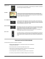
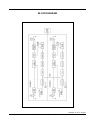
DRAWMER
Dual Channel
Vacuum Tube Compressor
OPERATOR’S MANUAL
CONTENTS
Warranty . . . . . . . . . . . . . . . . . . . . . . . . . . . . . . . . . . . . . . . . . . . . . . . . . . . . . . . . . . . 2
Safety Consideration . . . . . . . . . . . . . . . . . . . . . . . . . . . . . . . . . . . . . . . . . . . . . . . . 2
Chapter 1 - Introduction
Introduction . . . . . . . . . . . . . . . . . . . . . . . . . . . . . . . . . . . . . . . . . . . . . . . . . . . . . . . 3
Installation . . . . . . . . . . . . . . . . . . . . . . . . . . . . . . . . . . . . . . . . . . . . . . . . . . . . . . . . 4
Audio Connections . . . . . . . . . . . . . . . . . . . . . . . . . . . . . . . . . . . . . . . . . . . . . . . . . 4
Power Connection . . . . . . . . . . . . . . . . . . . . . . . . . . . . . . . . . . . . . . . . . . . . . . . . . 5
Chapter 2 - Control Description
Control Description . . . . . . . . . . . . . . . . . . . . . . . . . . . . . . . . . . . . . . . . . . . . . . . . . 6
The Quick Setup Procedure . . . . . . . . . . . . . . . . . . . . . . . . . . . . . . . . . . . . . . . . . 7
Chapter 3 - General Information
If a fault develops . . . . . . . . . . . . . . . . . . . . . . . . . . . . . . . . . . . . . . . . . . . . . . . . . . . 8
Contacting Drawmer . . . . . . . . . . . . . . . . . . . . . . . . . . . . . . . . . . . . . . . . . . . . . . . . 8
Specification . . . . . . . . . . . . . . . . . . . . . . . . . . . . . . . . . . . . . . . . . . . . . . . . . . . . . . 8
Block Diagram . . . . . . . . . . . . . . . . . . . . . . . . . . . . . . . . . . . . . . . . . . . . . . . . . . . . 9
COPYRIGHT
This manual is copyrighted 8 2011 by Drawmer Electronics Ltd. With all rights reserved. Under copyright
laws, no part of this publication may be reproduced, transmitted, stored in a retrieval system or translated
into any language in any form by any means, mechanical, optical, electronic, recording, or otherwise, without the written permission of Drawmer Electronics Ltd.
ONE YEAR LIMITED WARRANTY
Drawmer Electronics Ltd., warrants the Drawmer 1968 MkII
Dual Channel Vacuum Tube Compressor to conform
substantially to the specifications of this manual for a period
of one year from the original date of purchase when used in
accordance with the specifications detailed in this manual. In
the case of a valid warranty claim, your sole and exclusive
remedy and Drawmer’s entire liability under any theory of liability
will be to, at Drawmer’s discretion, repair or replace the product
without charge, or, if not possible, to refund the purchase price
to you. This warranty is not transferable. It applies only to the
original purchaser of the product.
For warranty service please call your local Drawmer dealer.
Alternatively call Drawmer Electronics Ltd. at +44 (0)1709
527574. Then ship the defective product, with transportation
and insurance charges pre-paid, to Drawmer Electronics Ltd.,
Coleman Street, Parkgate, Rotherham, S62 6EL UK. Write the
RA number in large letters in a prominent position on the
shipping box. Enclose your name, address, telephone number,
copy of the original sales invoice and a detailed description of
the problem. Drawmer will not accept responsibility for loss or
damage during transit.
This warranty is void if the product has been damaged by
misuse, modification or unauthorised repair.
THIS WARRANTY IS IN LIEU OF ALL WARRANTIES,
WHETHER ORAL OR WRITTEN, EXPRESSED, IMPLIED OR
STATUTORY. DRAWMER MAKES NO OTHER WARRANTY
EITHER EXPRESS OR IMPLIED, INCLUDING, WITHOUT
LIMITATION, ANY IMPLIED WARRANTIES OF
MERCHANTABILITY, FITNESS FOR A PARTICULAR PURPOSE,
OR NON-INFRINGEMENT. PURCHASER’S SOLE AND
EXCLUSIVE REMEDY UNDER THIS WARRANTY SHALL BE
REPAIR OR REPLACEMENT AS SPECIFIED HEREIN.
IN NO EVENT WILL DRAWMER ELECTRONICS LTD. BE
LIABLE FOR ANY DIRECT, INDIRECT, SPECIAL, INCIDENTAL
OR CONSEQUENTIAL DAMAGES RESULTING FROM ANY
DEFECT IN THE PRODUCT, INCLUDING LOST PROFITS,
DAMAGE TO PROPERTY, AND, TO THE EXTENT PERMITTED
BY LAW, DAMAGE FOR PERSONAL INJURY, EVEN IF
DRAWMER HAS BEEN ADVISED OF THE POSSIBILITY OF
SUCH DAMAGES.
DRAWMER
1968
MkII
Dual Channel
Vacuum Tube Compressor
SAFETY CONSIDERATIONS
CAUTION - MAINS FUSE
TO REDUCE THE RISK OF FIRE
REPLACE THE MAINS FUSE ONLY WITH
A FUSE THAT CONFORMS TO IEC127-2.
250 VOLT WORKING, TIME DELAY TYPE
AND BODY SIZE OF 20mm x 5mm.
THE MAINS INPUT FUSE MUST BE
RATED AT 230V=T160mA and 115V=T315mA.
CAUTION - MAINS CABLE
DO NOT ATTEMPT TO CHANGE
OR TAMPER WITH THE
SUPPLIED MAINS CABLE.
CAUTION - SERVICING
DO NOT PERFORM ANY SERVICING.
REFER ALL SERVICING TO QUALIFIED
SERVICE PERSONNEL.
WARNING
TO REDUCE THE RISK OF FIRE OR
ELECTRIC SHOCK DO NOT EXPOSE
THIS EQUIPMENT TO RAIN OR MOISTURE.
Some states and specific countries do not allow the exclusion
of implied warranties or limitations on how long an implied
warranty may last, so the above limitations may not apply to
you. This warranty gives you specific legal rights. You may
have additional rights that vary from state to state, and country
to country.
In the interests of product development, Drawmer reserve the right to modify or
improve specifications of this product at any time, without prior notice.
2
DRAWMER 1968 MkII OPERATOR’S MANUAL
CHAPTER 1
DRAWMER
1968 MkII
DUAL CHANNEL VACUUM TUBE COMPRESSOR
INTRODUCTION
The 1968 MkII is a 1U Tube/FET dual channel / ‘stereo
bus’ compressor which by design delivers a transparent
‘open’ sound even during periods of heavy compression.
The original Drawmer 1960 used a tube stage at the front
of the compressor, whilst the 1968 MkII utilisies a J-FET
(Field Effect Transistor) gain reduction circuit that operates
faster than an opto-isolator. The compressor uses a 12AX7
tube makeup gain amplifier where you can add, with the
Output Gain control, up to 20 dB of additional gain.
The need for a ratio control has been removed as the
compressor operates on the soft knee principle where the
onset of compression is progressive.
The 1968 MkII expands attack times to six choices: 2, 9,
15, 25, 30 and 50 ms. Release times come in three fixed
times (100ms, 500 ms and 1 second) and three programdependent choices--200 ms to 2 sec, 500 ms to 5 sec
and 1 to 10 seconds--all program-dependent and
automatic.
The 1968 MkII provides full sidechain access for connecting
an external equalizer for vocal stressing or de-essing.
Featured on both channels is a switchable ‘BIG’ and
‘BIGGER’ mode which applies less processing to the
fundamental low frequency but still disciplines the upward
associated harmonics which if untamed can result in a
‘boomy’ or ‘boxy’ sound. The result - a solid bottom end
with enhanced sub-bass and a smoother, wider frequency
response overall. This lets the operator use more
compression on an overall mix with less pumping action
caused by a kick and/or bass instrument.
The outputs of Channels 1 and 2 are monitored on two
yellow illuminated VU meters - with a red warning glow to
signify ‘approaching clipping’. A three-position switch
adjusts the meters to show either normal output level, gain
reduction or VU +10dB mode, which re-scales the meter
for users working at ‘hot’ output levels.
An output switch selects normal compressor output, hardwired bypass and sidechain listen.
The key features are as follows:
• 2 Channel Tube/FET Compressor
• 2 soft-knee compressors with variable threshold, attack, release and output gain
• Switchable BIG and BIGGER control on each channel
• Dual mono or true stereo link operation
• Side chain access and side chain listen facility
• VU metering of gain reduction and output levels
• Switchable +10dB mode on VU re-scales the meter for users working at ‘hot’ output levels.
• VU red warning glow to signify ‘approaching clipping’
• Balanced +4dB XLR in/outs
DRAWMER 1968 MkII OPERATOR’S MANUAL
3
INSTALLATION
The 1968 MkII is designed for standard 19" rack mounting
and occupies 1U of rack space. Avoid mounting the unit
directly above power amplifiers or power supplies that
radiate significant amounts of heat and always connect
the mains earth to the unit. Fibre or plastic washers may
be used to prevent the front panel becoming marked by
the mounting bolts. Because the tube circuitry generates
more heat than an equivalent solid-state design, it is
advisable to leave space above the unit to allow the heat to
dissipate.
AUDIO CONNECTIONS
The inputs and outputs are electronically balanced on conventionally wired XLRs (pin 1 screen, pin 2 hot, pin 3 cold and
XLR shell is connected to chassis). The operating level is nominally +4dBu. Balanced use is recommended.
• Interference:
If the unit is to be used where it maybe exposed to
high levels of disturbance such as found close to a TV
or radio transmitter, we advise that the unit is operated in a balanced configuration. The screens of the
signal cables should be connected to the chassis connection on the XLR connector as opposed to connecting to pin1. The 1968 MkII conforms to the EMC standards.
• Ground Loops:
If ground loop problems are encountered, never disconnect the mains earth, but instead, try disconnecting the signal screen on one end of each of the cables
connecting the outputs of the 1968 MkII to the
patchbay. If such measures are necessary, balanced
operation is recommended.
fig.1 1968 MkII WIRING
The side chain feature on the 1968 MkII is part of the compressor feedback stage and would normally be connected to
a normalised or semi-normalised pair of patchbay contacts. This would allow the user to insert additional EQ for some
de-essing, or frequency conscious compression. The side-chain access point is unbalanced, connection is via stereo
1/4" jacks, the wiring convention being: ring is signal send, tip is signal return and sleeve ground.
4
DRAWMER 1968 MkII OPERATOR’S MANUAL
POWER CONNECTION
The 1968 MkII unit will be supplied with a power cable suitable for domestic power outlets in your country. For your own
safety, it is important that you use this cable to connect to the mains supply earth. The cable must not be tampered with
or modified.
The power supply socket has an integral fuse drawer containing the power fuse of the same value, to suit the mains
voltage for which the unit has been supplied. Removal of the drawer is only possible with the power cord removed. The
fuse should never blow under normal operation. If the fuse is suspected of having blown, then a fault will have occurred
and this fault condition should be inspected by a qualified service engineer. When replacing the fuse, always comply with
the Safety Instructions.
If the unit is to be used with a mains input operating
voltage different to that for which the unit is supplied, the
following procedure must be carried out by a technically
competent person, (see following diagrams)
1: Disconnect the unit from the mains.
2: Using a number 1 size pozidrive screwdriver,
remove the seven self -tapping screws that retain the
top cover.Two screws are found along each side; two
along the top edge at the rear; and the upper central
screw on the front facia panel.
3: Slide the voltage change-over switch (SW8) until
the correct (or nearest) mains input voltage is visible
on the switch actuator.
(see fig.2)
For conversion to 115Volt AC (previously set to
230Volt AC).....
4a: Exchange the 160mA fuse below the mains
socket for a similar type rated at 315mA
fig.2 The Voltage Selector Switch
For conversion to 230Volt AC (previously set to
115Volt AC).....
4b: Exchange the 315mA fuse below the mains
socket for a similar type rated at 160mA
In addition another fuse is located inside the unit.
5:The on-board fuse protects the HT circuit and is
rated at T32mA: unclip the cover and replace the
fuse;
Fuse
fig.3 The Location of the Fuse
In all cases:
6: Replace the top cover using the seven screws.
7: Re-connect to mains power source.
DRAWMER 1968 MkII OPERATOR’S MANUAL
5
CHAPTER 2
CONTROL DESCRIPTION
Threshold:
Determines the input level above which gain reduction will be applied and may be
set in the range -30dB to infinity. Because the compression system is based on
the Soft Knee principle, the onset of compression is progressive, so no Ratio
control is necessary.
Big:
Makes the compressor side chain less sensitive to low bass frequencies, so
reducing the ducking effect caused by bass energy and effectively boosting the
bass output, the 'Bigger' option more so.
Attack:
Six switchable Attack settings are provided giving various settings. The actual
attack time is further modified by the release setting chosen
Attack Times:
1
2
3
4
5
6
2 ms
8 msec
15 msec
25 msec
30 msec
50 msec
Release:
There are three fixed Release times and a further three which are programme
dependent. Switch settings 1 through to 3 provide progressively increasing
release times, while positions 4, 5 and 6 cause the release times to vary in a
manner which automatically adapts to the dynamics of the incoming signal, as
detailed below.
Release Times
6
1
2
3
4
5
6
100 ms
(Fixed)
500 msec (Fixed)
1 sec
(Fixed)
Semi-Auto 200 ms to 2 sec Signal dependent
Semi-Auto 500 ms to 5 sec signal dependent
Automatic 1 sec to 10 sec signal dependent
DRAWMER 1968 MkII OPERATOR’S MANUAL
Output: (Gain)
The Output level may be amplified, or attenuated by up to 20dB to compensate
for level changes caused by compression.
VU Meter
A moving coil VU meter monitors either the level of the output signal or the
amount of gain reduction taking place. Because the meter has VU characteristics,
it closely reflects what is actually being heard, though will not respond quickly
enough to register short signal peaks.
VU +10dB/VU / GR
A three-position switch adjusts the meters to show either normal output level,
gain reduction or VU +10dB mode, which re-scales the meter for users working
at ‘hot’ output levels. In other words, with the switch at VU +10dB - when the VU
meter reads 0dB the actual level is +10dB.
Side Chain/Norm/Bypass
S/C Listen routes the side-chain signal directly to the output allowing the effects
of any additional side-chain processing, such as equalisation, to be monitored.
Normal mode, the signal is passed through the compressor.
Bypass takes the compressor and the vacuum tubes out of circuit path; the
output signal is taken from the channel input point.
Stereo Link
This makes Channel 1 controls the stereo master and disables the compressor
stage of channel 2 when the unit is used for processing a stereo signal. Since
the same gain reduction is applied to both audio channels no image shifting can
occur.
THE QUICK SETUP PROCEDURE
Use the following procedure to setup the compressor.
•
Initially, set the Attack selector to 3 (a Medium position) and set Release to
6 (Programme Dependent).
•
Set the Mode switch to Normal and the Meter switch to GR.
•
With programme material playing, adjust the Threshold control until the desired
amount of gain reduction registers on the meters.
•
Use the Output Gain control to restore any level lost due to compression.
•
If necessary, change the Attack and Release settings to suit the material.
DRAWMER 1968 MkII OPERATOR’S MANUAL
7
CHAPTER 3
GENERAL INFORMATION
It is the responsibility of the installer to ensure that the continuous power rating of the speakers is not exceeded, as Drawmer
Electronics Ltd will not accept any responsibitlity for speaker damage caused by incorrect settings.
IF A FAULT DEVELOPS
CONTACTING DRAWMER
For warranty service please call Drawmer Electronics Ltd. or
their nearest authorised service facility, giving full details of
the difficulty.
Drawmer Electronics Ltd., will be pleased to answer all
application questions to enhance your usage of this
equipment. Please address correspondence to:
A list of all main dealers can be found on the Drawmer
webpages.
On receipt of this information, service or shipping instructions
will be forwarded to you.
No equipment should be returned under the warranty without
prior consent from Drawmer or their authorised representative.
For service claims under the warranty agreement a service
Returns Authorisation (RA) number will be issued.
Write this RA number in large letters in a prominent position
on the shipping box. Enclose your name, address, telephone
number, copy of the original sales invoice and a detailed
description of the problem.
Authorised returns should be prepaid and must be insured.
Drawmer (Technical Help line)
Coleman Street
Parkgate
Rotherham
S62 6EL
UK
Alternatively contact us by E-mail on :
[email protected]
Further information on all Drawmer dealers, Authorised service
departments and other contact information can be obtained
from our web pages on:
http://www.drawmer.com
All Drawmer products are packaged in specially designed
containers for protection. If the unit is to be returned, the original
container must be used. If this container is not available, then
the equipment should be packaged in substantial shock-proof
material, capable of withstanding the handling for the transit.
1968 MkII DUAL CHANNEL VACUUM TUBE COMPRESSOR
DATA SPECIFICATION
INPUT IMPEDANCE
Input Impedance
Maximum Input Level
DISTORTION (THD & Noise)
Line Input with BYPASS selected
Line Input with NORMAL selected
20k Ohms
+20dBu
OUTPUT
Output Impedance
Maximum Output Level
POWER REQUIREMENTS
50 Ohms
+21dBu
230Volt or 115V at 50-60hZ, 13VA
FUSE RATING
BANDWIDTH
<17Hz to 28kHz -1dB
<10Hz to 47kHz -3dB
20mm x 5mm, Class 3 Slo-Blo, 250Volt working
-85dB
CASE SIZE
CROSSTALK
482mm (W) x 44mm (H) x 225mm (D)
better than 70dB @ 10kHz
better than 100dB @ 1kHz
8
160mA for 230Volt, 315mA for 115Volt
Conforming to IEC 127-2
FUSE TYPE
UNITY GAIN NOISE
22Hz - 22kHz (RMS)
1kHz
<0.01%
<0.35%
WEIGHT
DRAWMER 1968 MkII OPERATOR’S MANUAL
4Kgs
BLOCK DIAGRAM
1968mkII ver 02 A 03/05/11
DRAWMER 1968 MkII OPERATOR’S MANUAL
9
10
DRAWMER 1968 MkII OPERATOR’S MANUAL