1
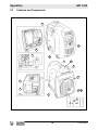
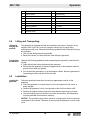
Operator’s Manual Inverter Generator GPi 1700 0179739en 0 1 7 9 002 7 3 0311 9 E N Copyright notice © Copyright 2010 by Wacker Neuson Corporation. All rights, including copying and distribution rights, are reserved. This publication may be photocopied by the original purchaser of the machine. Any other type of reproduction is prohibited without express written permission from Wacker Neuson Corporation. Any type of reproduction or distribution not authorized by Wacker Neuson Corporation represents an infringement of valid copyrights. Violators will be prosecuted. Trademarks All trademarks referenced in this manual are the property of their respective owners. Manufacturer Wacker Neuson Corporation N92W15000 Anthony Avenue Menomonee Falls, WI 53051 U.S.A. Tel: (262) 255-0500 · Fax: (262) 255-0550 · Tel: (800) 770-0957 www.wackerneuson.com Original instructions This Operator’s Manual presents the original instructions. The original language of this Operator’s Manual is American English. Foreword Foreword SAVE THESE INSTRUCTIONS—This manual contains important instructions for the machine models listed below. These instructions must be followed during installation and maintenance of the generator (and battery, if equipped). Machines covered in this manual Machine Documentation Expectations for information in this manual Machine Item Number GPi 1700 0620777, 0620778 Keep a copy of the Operator’s Manual with the machine at all times. Use the separate Parts Book supplied with the machine to order replacement parts. If you are missing either of these documents, please contact Wacker Neuson Corporation to order a replacement or visit www.wackerneuson.com. Contact Wacker Neuson Product Support for information on servicing and repairing the machine. When ordering parts or requesting service information, be prepared to provide the machine model number, item number, revision number, and serial number. This manual provides information and procedures to safely operate and maintain the above Wacker Neuson model(s). For your own safety and to reduce the risk of injury, carefully read, understand, and observe all instructions described in this manual. Wacker Neuson Corporation expressly reserves the right to make technical modifications, even without notice, which improve the performance or safety standards of its machines. The information contained in this manual is based on machines manufactured up until the time of publication. Wacker Neuson Corporation reserves the right to change any portion of this information without notice. CALIFORNIA Proposition 65 Warning: Engine exhaust, some of its constituents, and certain vehicle components, contain or emit chemicals known to the State of California to cause cancer and birth defects or other reproductive harm. Laws pertaining to spark arresters NOTICE: State Health Safety Codes and Public Resources Codes specify that in certain locations spark arresters be used on internal combustion engines that use hydrocarbon fuels. A spark arrester is a device designed to prevent accidental discharge of sparks or flames from the engine exhaust. Spark arresters are qualified and rated by the United States Forest Service for this purpose. In order to comply with local laws regarding spark arresters, consult the engine distributor or the local Health and Safety Administrator. Manufacturer’s This manual contains references to approved parts, attachments, and approval modifications. The following definitions apply: Approved parts or attachments are those either manufactured or provided by Wacker Neuson. Approved modifications are those performed by an authorized Wacker Neuson service center according to written instructions published by Wacker Neuson. wc_tx001233gb.fm 3 Foreword Unapproved parts, attachments, and modifications are those that do not meet the approved criteria. Unapproved parts, attachments, or modifications may have the following consequences: Serious injury hazards to the operator and persons in the work area Permanent damage to the machine which will not be covered under warranty Contact your Wacker Neuson dealer immediately if you have questions about approved or unapproved parts, attachments, or modifications. 4 wc_tx001233gb.fm GPi 1700 1 Foreword 3 Safety Information 7 1.1 1.2 1.3 1.4 1.5 1.6 1.7 2 Table of Contents Signal Words Found in this Manual ...................................................... 7 Machine Description and Intended Use ............................................... 8 Safety Guidelines for Operating the Machine ....................................... 9 Operator Safety While Using Internal Combustion Engines ............... 11 Guidelines for Service Safety ............................................................. 12 Label Locations .................................................................................. 13 Machine Labels .................................................................................. 14 Operation 2.1 2.2 2.3 2.4 2.5 2.6 2.7 2.8 2.9 2.10 2.11 2.12 2.13 2.14 2.15 2.16 2.17 17 Overview ............................................................................................ 17 Preparing the Machine for First Use ................................................... 17 Features and Components ................................................................. 18 Lifting and Transporting ...................................................................... 19 Installation .......................................................................................... 19 Power Requirements .......................................................................... 20 Use of Extension Cords ...................................................................... 21 Control Panel ...................................................................................... 22 Customer Connections ....................................................................... 24 Grounding the Generator ................................................................... 25 Fueling the Machine ........................................................................... 26 Before Starting ................................................................................... 27 Starting the Generator ........................................................................ 28 Using AC Power ................................................................................. 29 Using DC Power ................................................................................. 30 Stopping the Generator ...................................................................... 31 Emergency Shutdown Procedure ....................................................... 31 wc_bo0179739en_002TOC.fm 5 Table of Contents 3 Maintenance 3.1 3.2 3.3 3.4 3.5 3.6 3.7 4 GPi 1700 32 Periodic Maintenance Schedule ..........................................................32 Cleaning and Checking the Spark Plug ...............................................34 Cleaning the Air Cleaner Assembly .....................................................35 Changing the Engine Oil .....................................................................36 Cleaning the Spark Arrester ................................................................37 Cleaning the Fuel Filter .......................................................................38 Storing the Generator ..........................................................................39 Schematic 4.1 42 Schematic Components ......................................................................43 5 Basic Troubleshooting 44 6 Technical Data 45 6.1 6.2 Engine .................................................................................................45 Generator Data ....................................................................................46 6 wc_bo0179739en_002TOC.fm GPi 1700 1 1.1 Safety Information Safety Information Signal Words Found in this Manual This manual contains DANGER, WARNING, CAUTION, NOTICE, and NOTE signal words which must be followed to reduce the possibility of personal injury, damage to the equipment, or improper service. This is the safety alert symbol. It is used to alert you to potential personal hazards. f Obey all safety messages that follow this symbol. DANGER DANGER indicates a hazardous situation which, if not avoided, will result in death or serious injury. f To avoid death or serious injury from this type of hazard, obey all safety messages that follow this signal word. WARNING WARNING indicates a hazardous situation which, if not avoided, could result in death or serious injury. f To avoid possible death or serious injury from this type of hazard, obey all safety messages that follow this signal word. CAUTION! CAUTION indicates a hazardous situation which, if not avoided, could result in minor or moderate injury. f To avoid possible minor or moderate injury from this type of hazard, obey all safety messages that follow this signal word. NOTICE: Used without the safety alert symbol, NOTICE indicates a situation which, if not avoided, could result in property damage. Note: A Note contains additional information important to a procedure. wc_si000347gb.fm 7 Safety Information 1.2 GPi 1700 Machine Description and Intended Use This machine is a portable electric power source. The Wacker Neuson Inverter Generator consists of a gasoline engine, a fuel tank, and an electric alternator and inverter. Controls and receptacles are provided on a control panel mounted on the side of the machine. As the engine runs, the generator converts mechanical energy into AC power and DC power. The operator connects loads to the AC power receptacles or DC terminals. This machine is intended for the purpose of supplying electrical power to connected loads. Refer to the product specifications for the output voltage and frequency of this generator, and for the maximum output power limit of this generator. This machine has been designed and built strictly for the intended use described above. Using the machine for any other purpose could permanently damage the machine or seriously injure the operator or other persons in the area. Machine damage caused by misuse is not covered under warranty. The following practices are some examples of misuse: Connecting a load that has voltage and frequency requirements that are incompatible with the generator output Overloading the generator with a load that draws excessive power during either continuous running or start-up Operating the generator in a manner that is inconsistent with all federal, state and local codes and regulations. Using the machine as a ladder, support, or work surface Using the machine to carry or transport passengers or equipment Operating the machine outside of factory specifications Operating the machine in a manner inconsistent with all warnings found on the machine and in the Operator’s Manual This machine has been designed and built in accordance with the latest global safety standards. It has been carefully engineered to eliminate hazards as far as practicable and to increase operator safety through protective guards and labeling. However, some risks may remain even after protective measures have been taken. They are called residual risks. On this machine, they may include exposure to: Heat, noise, exhaust, and carbon monoxide from the engine Fire hazards from improper refueling techniques Fuel and its fumes Electric shock and arc flash Personal injury from improper lifting techniques To protect yourself and others, make sure you thoroughly read and understand the safety information presented in this manual before operating the machine. 8 wc_si000347gb.fm GPi 1700 1.3 Safety Information Safety Guidelines for Operating the Machine DANGER Carbon monoxide. Using a generator indoors CAN KILL YOU IN MINUTES. Generator exhaust contains carbon monoxide (CO). This is a poison you cannot see or smell. If you can smell the generator exhaust, you are breathing CO. But even if you cannot smell the exhaust, you could be breathing CO. f NEVER use a generator inside homes, garages, crawlspaces, or other partly enclosed areas. Deadly levels of carbon monoxide can build up in these areas. Using a fan or opening windows and doors does NOT supply enough fresh air. f ONLY use a generator outside and far away from windows, doors, and vents. These openings can pull in generator exhaust. f Even when you use a generator correctly, CO may leak into the home. ALWAYS use a battery-powered or battery-backup CO alarm in the home. f If you start to feel sick, dizzy, or weak after the generator has been running, move to fresh air RIGHT AWAY. See a doctor. You could have carbon monoxide poison. WARNING Machines operated improperly or by untrained personnel can be hazardous. f Read the operating instructions contained in both this Operator’s Manual and the engine operator’s manual. f Familiarize yourself with the location and proper use of all controls. f Inexperienced operators should receive instruction from someone familiar with the machine before being allowed to operate it. Operator qualifications Only trained personnel are permitted to start, operate, and shut down the machine. They also must meet the following qualifications: have received instruction on how to properly use the machine are familiar with required safety devices The machine must not be accessed or operated by: children people impaired by alcohol or drugs Personal Protective Equipment (PPE) Wear the following Personal Protective Equipment (PPE) while operating this machine: Close-fitting work clothes that do not hinder movement Safety glasses with side shields Hearing protection Safety-toed footwear Before starting the machine Before starting this machine: Follow starting and stopping instructions described in this manual. Know how to operate and stop the generator before starting it. Do not start a machine in need of repair. wc_si000347gb.fm 9 Safety Information Electrical safety GPi 1700 Make sure the machine is on a firm, level surface and will not tip, roll, slide, or fall while operating. Remove all tools, cords, and other loose items from the generator before starting it. To increase electrical safety while operating this machine: Do not operate the generator, or tools attached to the generator, with wet hands. Do not use worn electrical cords. Severe electrical shock and equipment damage may result. Do not operate generator in standing water. Make certain the machine is well-grounded and securely fastened to a good earthen ground per national and local regulations. Do not overload the generator. The total amperage of the tools and equipment attached to the generator must not exceed the load rating of the generator. . WARNING Backfeed from the generator into the public power distribution system can seriously injure or kill utility workers! f Improper connection of generator to a building’s electrical system can allow electrical current from the generator to backfeed into utility lines. This may result in electrocution of utility workers, fire, or explosion. f Connections to a building’s electrical system must be made by a qualified electrician and comply with all applicable laws and electrical codes. f If connected to a building’s electrical system, the generator must meet the power, voltage, and frequency requirements of the equipment in the building. Generator vibration Generators vibrate in normal use. During and after the use of the generator, inspect the generator as well as extension cords and power supply cords connected to it for damage from vibration. Have damaged items repaired or replaced as necessary. Do not use plugs or or cords that show signs of damage such as broken or cracked insulation or damaged blades. Operating safety To increase operating safety while running this machine: Do not operate the generator when open containers of fuel, paint, or other flammable liquids are in the vicinity of the generator. Do not place flammable material or liquids near the generator. Do not operate the machine indoors. Do not touch the hot engine, exhaust, or generator components. Burns will result. Always do the following: Wear hearing protection when operating equipment. Keep the machine at least one meter (three feet) away from structures, buildings, and other equipment during use. Keep the area immediately surrounding and underneath the machine clean, neat, and free of debris and combustible materials. Make sure that the area 10 wc_si000347gb.fm GPi 1700 Safety Information overhead is clear of debris that could fall onto or into the machine or exhaust compartment. Storing the machine 1.4 Store the machine properly when it is not being used. The machine should be stored in a clean, dry location out of the reach of children. Operator Safety While Using Internal Combustion Engines WARNING Internal combustion engines present special hazards during operation and fueling. Failure to follow the warnings and safety standards could result in severe injury or death. f Read and follow the warning instructions in the engine owner’s manual and the safety guidelines below. DANGER Carbon monoxide. Using a generator indoors CAN KILL YOU IN MINUTES. Generator exhaust contains carbon monoxide (CO). This is a poison you cannot see or smell. If you can smell the generator exhaust, you are breathing CO. But even if you cannot smell the exhaust, you could be breathing CO. Refueling safety When refueling the engine: Do not smoke. Do not refuel if the generator is sitting in a truck fitted with a plastic bed liner. Static electricity can ignite the fuel or fuel vapors. Do not refuel a hot or running engine. Do not refuel the engine near an open flame. When refueling the engine, always: Refill the fuel tank in a well-ventilated area. Replace the fuel tank cap after refueling. Operating safety wc_si000347gb.fm When operating the generator: Check the fuel lines and the fuel tank for leaks and cracks before starting the engine. Do not run the machine if fuel leaks are present or the fuel lines are loose. Do not run the engine near open flames. Do not start the engine if fuel has spilled or a fuel odor is present. Move the generator away from the spill and wipe the generator dry before starting. Do not smoke while operating the machine. 11 Safety Information 1.5 GPi 1700 Guidelines for Service Safety WARNING A poorly maintained machine can be a personal injury hazard. f Follow the Periodic Maintenance schedule in this Operator’s Manual. f Repair or replace any damaged or defective components immediately. Personal Protective Equipment (PPE) Wear the following Personal Protective Equipment (PPE) while servicing or maintaining this machine: Close-fitting work clothes that do not hinder movement Safety glasses with side shields Hearing protection Safety-toed footwear In addition, before servicing or maintaining the machine: Tie back long hair. Remove all jewelry (including rings). Prerequisites Before servicing this machine: Stop the engine. If the engine has an electric starter, disconnect the negative terminal on the battery. Attach a “DO NOT START” sign to the machine. This will notify everyone that the machine is being serviced and will reduce the chance of someone inadvertently trying to start the machine. Ground connection Personal injury avoidance Service safety The generator must be connected to a good earthen ground for proper operating safety! Ground the generator in accordance with the standards defined in national, state, and local regulations. Let the engine and muffler cool before transporting or servicing the machine. Do not service the machine if your clothing or skin is wet. Do not allow untrained personnel to service this machine. Only trained electrical technicians should be allowed to service the electrical components of this machine. Do not modify the machine without the express written approval of the manufacturer. Do not allow water to accumulate around the base of the machine. If water is present, move the machine and allow the machine to dry before servicing. .. Replacing parts and labels Replace worn or damaged components. Use only spare parts recommended by Wacker Neuson. Keep the fuel lines in serviceable condition. Leaking fuel and fumes are extremely explosive! Replace all missing and hard-to-read labels. Labels provide important operating instructions and warn of dangers and hazards. Check all external fasteners at regular intervals. 12 wc_si000347gb.fm GPi 1700 1.6 Safety Information Label Locations C A D E H F G B wc_gr006811 wc_si000347gb.fm 13 Safety Information 1.7 GPi 1700 Machine Labels Wacker Neuson machines use international pictorial labels where needed. These labels are described below. Ref. Label Definition A DANGER Using a generator indoors CAN KILL YOU IN MINUTES. Generator exhaust contains carbon monoxide. This is a poison you cannot see or smell. NEVER use inside a home or garage, EVEN IF doors and windows are open. Only use OUTSIDE and far away from windows, doors, and vents. B Oil fill location 14 wc_si000347gb.fm GPi 1700 Safety Information Ref. wc_si000347gb.fm Label Definition C WARNING To reduce the risk of injury, user must read and understand instruction manual. Exhaust gas contains poisonous carbon monoxide. Do not use in poorly ventilated area. The operator may suffer severe elecrtric shock. Do not touch with wet hands. The operator may suffer burns. Do not touch hot muffler. Potential danger of explosion or fire. Stop engine during fuel supply. Keep flammable things away. Be careful not to spill fuel during refueling. Use unleaded gasoline only. Keep open flames away from the generator. Do not operate in rain or snow. Do not connect to a household circuit. D This equipment does not meet California EVP emission regulations for small off-road engines. E WARNING Improper connection of the generator to a building’s electrical system can allow electrical current from the generator to backfeed into utility lines. This may result in electrocution of utility workers, fire, or explosion. Connections to a building’s electrical system must be made by a qualified electrician and comply with all applicable laws and electrical codes. F A nameplate listing the model number, item number, revision number, and serial number is attached to each unit. Please record the information found on this nameplate so it will be available should the nameplate become lost or damaged. When ordering parts or requesting service information, you will always be asked to specify the model number, item number, revision number, and serial number of the unit. 15 Safety Information Ref. GPi 1700 Label Definition G WARNING Hot surface! Do not touch. DANGER Risk of carbon monoxide poisoning. Keep a safe distance away from the machine. H WARNING Hot surface! Do not touch. 16 wc_si000347gb.fm GPi 1700 2 Operation Operation DANGER Carbon monoxide. Using a generator indoors CAN KILL YOU IN MINUTES. Generator exhaust contains carbon monoxide (CO). This is a poison you cannot see or smell. If you can smell the generator exhaust, you are breathing CO. But even if you cannot smell the exhaust, you could be breathing CO. f NEVER use a generator inside homes, garages, crawlspaces, or other partly enclosed areas. Deadly levels of carbon monoxide can build up in these areas. Using a fan or opening windows and doors does NOT supply enough fresh air. f ONLY use a generator outside and far away from windows, doors, and vents. These openings can pull in generator exhaust. f Even when you use a generator correctly, CO may leak into the home. ALWAYS use a battery-powered or battery-backup CO alarm in the home. f If you start to feel sick, dizzy, or weak after the generator has been running, move to fresh air RIGHT AWAY. See a doctor. You could have carbon monoxide poison. 2.1 Overview Generator application This generator is an exceptionally quiet, compact, and lightweight machine designed to provide single phase power for construction, commercial, and residential applications. State-of-the-art inverter technology ensures a consistent flow of clean and stable power suitable for operating not only tools, but also delicate electronic equipment. Safety notices 2.2 Do not exceed the power output of the generator. Damage to tools or generator will occur. Refer to Technical Data. Do not exceed the rated current limit of any receptacle. Preparing the Machine for First Use Preparing for first use To prepare your machine for first use: 1. Make sure all loose packaging materials have been removed from the machine. 2. Check the machine and its components for damage. If there is visible damage, do not operate the machine! Contact your Wacker Neuson dealer immediately for assistance. 3. Take inventory of all items included with the machine and verify that all loose components and fasteners are accounted for. 4. Attach component parts not already attached. 5. Add fluids as needed and applicable, including fuel, engine oil, and battery acid. 6. Move the machine to its operating location. wc_tx001234gb.fm 17 Operation 2.3 GPi 1700 Features and Components l a b d e c f n g o l k h m j i wc_gr006650 18 wc_tx001234gb.fm GPi 1700 2.4 Operation Ref. Description Ref. Description a Recoil starter i OIl drain plug b Control panel j Right side panel c Left side panel k Oil filler / oil gauge d Air cleaner l Spark plug cap e Fuel drain screw m Spark arrester f Carrying handle n Fuel filter g Fuel tank cap cover o Rear cover h Exhaust outlet — — Lifting and Transporting Lifting and carrying the machine This generator is designed be lifted and carried by one person. However, its dry weight of 20.5 kg (45 lbs.) is heavy enough to cause injury if proper lifting techniques are not used. Observe the following guidelines when lifting and carrying the generator. Use only the designated carrying handle. Bend at the knees, not from the waist, when lifting the generator. Transporting the machine Observe the following guidelines when transporting the generator to and from the job site. Drain the fuel tank before transporting the generator. Ensure that the generator is securely strapped down in the transport vehicle to prevent it from sliding or tipping. Do not refuel the generator in or on the transport vehicle. Move the generator to its operating location and then fill the fuel tank. 2.5 Installation Locating the generator Follow the practices below when choosing an appropriate location for the generator. Place the generator in an area where it will not be exposed to rain, snow, or direct sunlight. Position the generator on firm, level ground so that it will not slide or shift. Position the engine exhaust away from areas where people may be present. The surrounding area must be free from water and moisture. All components must be protected from excessive moisture. NOTICE: The generator has a built-in forced air cooling system, and may become overheated if it is enclosed. Therefore, do not enclose the generator or cover it with a box. wc_tx001234gb.fm 19 Operation 2.6 GPi 1700 Power Requirements Application This generator is designed to operate single-phase, 60 Hz equipment running at 120 VAC. It also provides DC power strictly intended for charging 12V automotive style batteries. Check the nameplate or label provided on tools and equipment to make sure their power requirements are met by the power output of the generator. If the wattage is not given for a particular tool or piece of equipment, contact the tool manufacturer for wattage requirements. NOTICE: Do not exceed the continuous rated output of the generator. Damage to tools or generator can occur. See Technical Data. About power requirements Some pieces of equipment and tools require a surge of current when starting. This means that the amount of power needed to initially start the equipment is larger than the power required to keep it running. The generator must be capable of supplying this "surge" current. Other equipment may require more power than is actually stated on its nameplate. Approximate The information in the following chart is offered only as a general guideline to help starting power you determine power requirements for different types of equipment. Contact your requirements nearest Wacker Neuson dealer, or the manufacturer or dealer of the tool or equipment, with questions regarding power requirements. Equipment type Wattage needed to start Comments Incandescent lights Appliances such as irons and hot plates Same wattage as is stated on their nameplates These have resistivetype heating elements. Fluorescent and mercury lamps 1.2–2 times their stated wattage Electrical motors Certain electrical tools Depends on motor type and use Most electrical tools 1.2–3 times their stated wattage Submersible pumps Air compressors 3–5 times their stated wattage Other equipment Calculate by multiplying its voltage and amperage requirements 20 Volts x Amps = Watts wc_tx001234gb.fm GPi 1700 2.7 Operation Use of Extension Cords When a long extension cord is used to connect an appliance or tool to the generator, a voltage loss occurs—the longer the cord, the greater the voltage loss. This results in less voltage being supplied to the appliance or tool and increases the amount of current draw or reduces performance. A heavier cord with a larger wire size will reduce the voltage loss. WARNING Electric shock hazard. Damaged extension cords can cause electrical shock, resulting in serious injury or death. DO NOT use worn, bare, or frayed cords. f Replace damaged cords immediately. Use the chart below as a guide for selecting proper cable size. Current Load in Watts Maximum Cable Length in Feet (Amps) 120V 240V #10 #12 #14 #16 2.5 300 600 1000. 600 375 250 5 600 1200 500 300 200 125 7.5 900 1800 350 200 125 100 10 1200 2400 250 150 100 - 15 1800 3600 150 100 65 - 20 2400 4800 125 75 50 - Use only extension cords rated for outdoor use and equipped with a third-wire ground. NOTICE: Operating equipment at low voltage can cause it to overheat. wc_tx001234gb.fm 21 Operation 2.8 GPi 1700 Control Panel p q r s t u v CHOKE y w x wc_gr006445 Ref. Description Ref. Description p Pilot indicator light u GFI receptacle (120 VAC) q Overload indicator light v DC terminals r Oil sensor indicator light w DC circuit breaker s Auto power save indicator light x Ground lug t Auto power save switch y Engine switch Pilot indicator light (p) The pilot indicator light illuminates when the generator is operating normally. Overload indicator light (q) The overload indicator light illuminates when the generator is operating in an overload condition. An overload condition is defined as 120% of the available power output of the generator. After the indicator light has been illuminated for 20 seconds, an internal circuit breaker will activate resulting in a no-load condition. If the indicator light illuminates, stop and re-start the engine to clear the overload condition and resume normal operation. Oil sensor indicator light (r) The oil sensor indicator light illuminates when the level of the engine oil falls below the prescribed value. The engine stops automatically. The engine cannot be re-started unless engine oil is added. Follow the procedure described in Adding Engine Oil. 22 wc_tx001234gb.fm GPi 1700 Auto power save indicator light (s) and switch (t) Operation The auto power save indicator light illuminates when the auto power save switch (t) is in positions 1 or 2. With the switch in position 1 (“turtle”), the engine speed automatically adjusts according to the generator load. With the switch in position 2 (“rabbit”), the engine speed remains constant to maintain stable AC power output. This position is ideal for heavy loads. Turn the switch OFF when using DC power. GFI receptacle AC power is available through this receptacle. Use only a grounded, three-leg (u) electrical plug. DC terminals (v) The generator provides DC power for charging batteries. The red terminal is positive (+); the black terminal is negative (-). See topic Using DC Power. DC circuit breaker (w) The DC circuit breaker shuts off the electrical current when the current exceeds its limit, or a malfunction occurs in a piece of equipment connected to the generator. The DC circuit breaker has activated when the button pops out. To reset the DC circuit breaker, press the button. CAUTION Electric shock hazard. Repeated activation of the DC circuit breaker could signal a potential malfunction with the generator or connected equipment. f Never defeat the DC circuit breaker button or reset it without first investigating the reason for the activation. Ground lug (x) The ground lug is the terminal for grounding the generator. See topic Grounding the Generator for more information. Engine switch (y) The engine switch controls the function of the choke and the fuel valve. There are three positions: Symbol wc_tx001234gb.fm Meaning Description Choke valve is closed Turn the switch to this position when starting a cold engine. Normal operating position Turn the switch to this position after the engine starts. Note: A warm engine can be started with the switch in this position. Fuel valve is closed Turn the switch to this position to stop the engine. 23 Operation 2.9 GPi 1700 Customer Connections Description The generator is equipped with : one 120V duplex receptacle (u) with a ground fault circuit interrupt (GFI) one pair of DC terminals (v) exclusively intended for charging 12V automotivestyle batteries. See Using DC Power for more information. u2 u1 u v wc_gr006739 Testing GFI operation The GFI cuts power to the receptacle when a ground fault occurs to a piece of equipment attached to the generator. Follow the procedure below to test the GFI for proper operation every time the generator is used. 1. Disconnect all equipment from the generator. 2. Start the generator. 3. Push the blue TEST button (u1) on the receptacle. Pushing the TEST button in cuts power to the receptacle and causes the red RESET button (u2) to pop out. NOTICE: If the RESET button does not pop out, the GFI is not working. Do not operate the generator until the problem can be corrected. 4. Push the RESET button to restore power to the receptacle. If the RESET button pops out during operation, stop the generator and check the equipment attached to the generator for defects. 24 wc_tx001234gb.fm GPi 1700 2.10 Operation Grounding the Generator Location The ground lug (x) is located below the DC terminals. x x1 wc_gr006652 Function This ground connection is used for electrically grounding the generator when necessary to comply with the National Electrical Code and other federal, state, and local regulations. For grounding requirements in your area, consult with a qualified electrician, electrical inspector, or local agency having jurisdiction over electrical compliance. If the generator is used at a construction site, there may be additional regulations which must be observed. In some areas, generators are required to be registered with local utility companies. Connection Connect the ground lug to a good earthen ground for proper operating safety in compliance with NEC and local standards. The following options may be used: Connect the ground lug to a grounding spike (x1) and drive the grounding spike into the earth. Connect the ground lug to an existing grounded conductor. wc_tx001234gb.fm 25 Operation 2.11 GPi 1700 Fueling the Machine Fuel filler cap The fuel filler cap (g1) is located beneath the fuel tank cap cover (g). Turn the fuel filler cap counter-clockwise to open; clockwise to close. g g3 g1 a g2 g v wc_gr006653 WARNING Fire/burn hazards. Gasoline is flammable and can ignite or explode. f Keep all open flames, sparks, and cigarettes away from the machine while refueling. f Do not refuel if the generator is sitting in a truck fitted with a plastic bed liner. Static electricity can ignite the fuel or fuel vapors. f Do not refuel when the engine is running or hot. Filling the fuel tank Follow the guidelines below when filling the fuel tank. Turn the engine switch (v) to STOP before refueling. Refuel only with clean, fresh unleaded gasoline. Add fuel through the fuel filter screen (g2), making sure that dirt or water do not enter the fuel tank. Fill only until the fuel level reaches the red LEVEL indicator (g3) inside the fuel tank neck. Do not overfill! Clean up spilled fuel before operating the machine. Fuel tank capacity = 3.5 L (0.92 gal.). Priming the fuel system When using the generator for the first time, or if the fuel tank runs dry and the engine stops as a result, the fuel system will require priming before re-start. To prime the fuel system, pull the recoil starter handle (a) several times after filling fuel up to the red marking inside the fuel tank neck. Using gasoline / ethanol blends This portable generator is not for use with gasoline / ethanol blends with over 15% ethanol. 26 wc_tx001234gb.fm GPi 1700 2.12 Operation Before Starting DANGER Carbon monoxide. Using a generator indoors CAN KILL YOU IN MINUTES. Generator exhaust contains carbon monoxide (CO). This is a poison you cannot see or smell. If you can smell the generator exhaust, you are breathing CO. But even if you cannot smell the exhaust, you could be breathing CO. Explanation Before putting the generator into service, review each item on the following checklist. It is important to make sure that the machine is set up properly to reduce the possibility of malfunction. WARNING Personal injury hazard. Failure to follow the listed procedures may cause injury to personnel or damage to the generator. f Make sure that all persons setting up the generator are certified or fully trained on the installation and operation of the generator. Exterior checks Internal and pre-operation checks wc_tx001234gb.fm Before starting the generator: check for damage that may have occurred during towing or travel to the jobsite check for fuel leaks check for loose or missing fasteners make sure the exhaust pipe is not clogged with debris make sure that the generator is level make sure the generator is not resting on against any adjacent wiring make sure that the generator air vents are not blocked make sure that the generator is grounded to a good earthen ground per local regulations and NEC standards check engine oil and fuel levels—fill as required determine voltage needs review and follow safety instructions found in the front of this Operator’s Manual 27 Operation 2.13 GPi 1700 Starting the Generator CAUTION Personal injury or machine damage hazards. Starting the generator with equipment attached can damage the generator or the equipment. Unexpected equipment start-up can cause personal injury. f Disconnect all equpment from the generator before starting it. Starting procedure Follow the procedure below to start the machine. 1. Turn the engine switch (y) to the CHOKE position (or the RUN position if the engine is warm or the ambient temperature is high). p a y wc_gr006656 2. Pull the recoil starter (a) slowly until you feel resistance. 3. After you feel resistance, return the recoil starter to its original position and pull quickly. The engine will start. 4. If you started the machine with the engine switch in the CHOKE position, allow the engine to run for 20–30 seconds and then turn the engine switch to the RUN position. 5. Check to make sure that the pilot indicator light (p) is illuminated. This indicates that the generator is operating properly. Troubleshooting If the engine does not start after several attempts, repeat the starting procedure with the engine switch turned to the RUN position. If the engine still does not start, refer to the Troubleshooting chapter in this Manual. 28 wc_tx001234gb.fm GPi 1700 2.14 Operation Using AC Power Prerequisites Verify that the engine is operating. Verify that pilot indicator light (p) is illuminated. Turn off the equipment to be connected to the generator. Confirm that the equipment to be connected to the generator does not exceed the maximum rated power output and specifed amperage. WARNING Electric shock hazard. Failure to properly ground the generator could lead to electrical sparks, especially if the connected electrical equipment is grounded. f Make sure the generator is properly grounded. See Grounding the Generator. Engine switch position Leave the engine switch (y) in the RUN position while the machine is operating. p u u y wc_gr006657 Connecting equipment 1. Insert the equipment plug into the 120V AC GFI receptacle (u). 2. Turn on the power switch for the equipment. Disconnecting 3. Turn off the power switch for the equipment. equipment 4. Remove the plug from the 120V AC GFI receptacle. wc_tx001234gb.fm 29 Operation 2.15 GPi 1700 Using DC Power Overview The DC terminals (v) are to be used only for charging 12V batteries. Maximum available power is 12V–8.3A (100W). Both AC and DC output can be used at the same time provided that the total output falls below the maximum rated output of the generator. Prerequisites Verify that pilot indicator light (p) is illuminated. Make sure that the charging cables to be used are rated for 12 V and the maximum CCA rating of the battery. WARNING Personal injury hazard. Battery acid is corrosive to metallic surfaces and harmful to human skin. f Wear protective clothing, goggles and gloves when working near batteries. f If battery acid contacts the skin or eyes, rinse immediately with clear water and seek immediate medical attention. WARNING Explosion hazard. Explosive hydrogen gas is discharged through battery vent holes during the charging process. f Do not use open flames or smoke near batteries. f Do not place metallic objects on or near the battery terminals. Metallic objects in contact with both poles of the battery will generate extreme heat and potentially ignite explosive battery gases. Engine switch position Leave the engine switch (y) in the RUN position while the generator is operating. p v2 v1 v y wc_gr006738 Connecting and charging a battery Follow the procedure below to connect and charge a battery. 1. Connect the positive terminal (v1) (red) on the generator to the positive (+) battery terminal. 2. Connect the negative terminal (v2) (black) on the generator to the negative (-) battery terminal. 3. Charge the battery for the recommended length of time prescribed by the battery manufacturer. 30 wc_tx001234gb.fm GPi 1700 Operation Disconnecting When the battery is fully charged: the battery 1. Disconnect the cable from the negative (-) terminals of the battery and the generator. 2. Disconnect the cable from the positive (+) terminals of the battery and the generator. If the DC The DC circuit breaker may activate while a battery is charging. This may occur for circuit breaker either of the following reasons: activates Defective battery—check the battery before replacing the DC breaker Excessive current draw from a large capacity battery or a totally discharged battery—use an AC battery charger to charge the battery instead of the generator. 2.16 Stopping the Generator Before stopping Check with other personnel on the jobsite and let them know that power is being turned off. Make sure that the power shutdown will not create any hazards by turning off devices such as pumps, heaters, or lights that may need to be kept on. Stopping procedure To stop the generator: 1. Switch off and disconnect all equipment from the generator. 2. Allow the generator to run at no load for approximately 3 minutes. 3. Turn the engine switch to the STOP position. 2.17 Emergency Shutdown Procedure Procedure If a breakdown or accident occurs while the machine is operating, follow the procedure below: 1. Stop the engine. 2. Turn off the fuel supply. 3. Disconnect tools from the machine. 4. Allow the machine to cool. 5. Contact the rental yard or machine owner for further instructions. wc_tx001234gb.fm 31 Maintenance 3 3.1 GPi 1700 Maintenance Periodic Maintenance Schedule The table below lists basic machine and engine maintenance. Tasks designated with check marks may be performed by the operator. Tasks designated with square bullet points require special training and equipment. Refer to the engine owner’s manual for additional information. Every 8 hours (daily) Clean generator enclosure Check for loose or missing fasteners Check engine oil level and refill as needed Every 100 hours (biweekly) Every 200 hours (monthly) Every 500 hours Every 1000 hours 3 3 3 Check AC receptacles for dirt or blockage; test GFI 3 Check DC terminals for damage or dirt 3 3 Check engine switch for proper operation Every 50 hours (weekly) 3 3 Clean spark plug Clean air cleaner Change engine oil1 Clean spark arrester Replace air cleaner insert Clean fuel filter 3 3 Clean and adjust spark plug and electrodes Replace spark plug Remove carbon from cylinder head2 Check and adjust valve clearance2 Check and adjust carburetor2 Replace fuel lines3 Overhaul engine2 Check generator rotor Check generator stator Replace engine mount 1 Perform initial oil change after first 20 hours of operation. 2 Refer to the engine service manual or consult an authorized Wacker Neuson service center 3 Replace yearly Checking the Engine Oil 32 wc_tx001235gb.fm GPi 1700 Maintenance When Check engine oil daily before starting the engine, or more than 5 minutes after stopping the engine. Prerequisites Engine is stopped Machine is on a level surface Fresh oil is available (see Technical Data for type and quantity) WARNING Burn hazard. The engine and exhaust pipe become extremely hot during operation. f Stop the engine and allow the machine to cool before checking the engine oil. Procedure Follow the procedure below to check the engine oil level. 1. Using a flat screwdriver or a coin, unscrew and remove the right side cover (j) from the generator enclosure. k1 k k2 j 2. Unscrew and remove the oil filler cap (k) with level gauge from the oil fill port. 3. Wipe the level gauge clean and insert it into the oil fill port. 4. Remove the level gauge from the oil fill port and check the oil level. The oil level should fall between the upper and lower marks (k1, k2). 5. If the oil level is too low, add oil until the level reaches the upper mark (k1). 6. Re-install the oil filler cap and tighten it securely. 7. Re-install the right side cover. Note: Change the oil if it appears dark, dirty, or contaminated. See “Changing the Engine Oil.” wc_tx001235gb.fm 33 Maintenance 3.2 GPi 1700 Cleaning and Checking the Spark Plug When Clean the spark plug and check the electrode gap every 200 hours of operation (monthly). Prerequisite Engine is stopped and cool to the touch WARNING Burn hazard. Engine and exhaust pipe become extremely hot during operation. f Stop the engine and allow the machine to cool before cleaning and adjusting the spark plug. Removing and Follow the procedure below to remove and clean the spark plug. cleaning the 1. Using a flat screwdriver or a coin, unscrew and remove the right side cover (J) spark plug from the generator enclosure. L2 L1 L J wc_gr006660 2. Disconnect the spark plug cap (L) from the spark plug (L2). 3. Using the provided spark plug wrench (L1), unscrew and remove the spark plug. 4. If the electrode is covered with carbon deposits, use a wire brush or spark plug cleaner to remove the carbon. NOTICE: If the spark plug is cracked or damaged, replace it. See Technical Data. Checking the electrode gap 5. The electrode gap should measure between 0.6 to 0.7 mm (0.024 to 0.028 in.). Adjust the gap if necessary. Re-installing 6. Re-install the spark plug and tighten it securely. the spark plug NOTICE: A loose spark plug can become very hot and may cause engine damage. Make sure that the spark plug is properly seated and tightened. 7. Re-connect the spark plug cap. 8. Re-install the right side cover. 34 wc_tx001235gb.fm GPi 1700 3.3 Maintenance Cleaning the Air Cleaner Assembly When Clean the air cleaner assembly every 50 hours of operation. Prerequisite Engine is stopped and cool to the touch Description The air cleaner assembly consists of a foam insert housed inside the air cleaner body. Procedure Follow the procedure below to clean the air cleaner assembly. c d1 d wc_gr006659 1. Using a flat screwdriver or a coin, unscrew and remove the left side cover (c) from the generator enclosure. 2. Lift and remove the air cleaner body cover (d). 3. Remove the foam insert (d1) from the air cleaner body. 4. Rinse the foam insert with clean water. Gently squeeze out excess water (do not twist) and dry the foam insert thoroughly. NOTICE: If the foam insert is damaged or heavily soiled, replace it. 5. Wipe the inside of the air cleaner body with a clean, dry cloth. 6. Re-install the foam insert inside the air cleaner body. 7. Re-install the air cleaner body cover and the left side cover. wc_tx001235gb.fm 35 Maintenance 3.4 GPi 1700 Changing the Engine Oil When Change the engine oil after the first 20 hours of operation, and every 50 hours thereafter. Prerequisites Engine is stopped, but still warm Machine is on a level surface Fresh engine oil (see engine operator’s manual) Plastic cloth and a container of sufficient volume to collect drained oil Note: Collect, store and dispose of drained oil in accordance with current environmental protection regulations. WARNING Burn hazard. Engine and exhaust pipe become extremely hot during operation. f Stop the engine and allow the machine to cool before changing the engine oil. Changing the engine oil Follow the procedure below to change the engine oil 1. Place a plastic cloth and a collection container beneath the machine. 2. Using a flat screwdriver or a coin, unscrew and remove the right side cover (j) from the generator enclosure. k k3 j wc_gr006743 3. Unscrew and remove the oil filler cap (k) with level gauge from the oil fill port. 4. The oil drain plug (k3) is located on the underside of the machine. Remove the oil drain plug. Drain the oil into a suitable container. 5. Re-install the oil drain plug. 6. Add new engine oil to the upper line of the level gauge. When the proper oil level is reached, re-install the oil filler cap. See Checking the Engine Oil. 7. Re-install the right side cover. 36 wc_tx001235gb.fm GPi 1700 3.5 Maintenance Cleaning the Spark Arrester When Clean the spark arrester after every 100 hours of operation. Prerequisite Engine is stopped and cool to the touch Description The spark arrester is a cylindrical metal element fastened inside the muffler exhaust port. If the spark arrester is not cleaned regularly, it will become clogged with carbon deposits and impair engine performance. Engine exhaust gases will not flow. Engine output will be reduced. More fuel will be consumed. Starting will become difficult. CAUTION Personal injury hazards. The spark arrester screen is made of stiff metal wire. Sharp wire ends can puncture or cut skin. Carbon dust can get into eyes. f Wear protective gloves and eye protection when cleaning the spark arrester. Procedure Follow the procedure below to clean the spark arrester. o1 m1 h1 o m h wc_gr006813 1. Remove the four screws (o1) from the rear cover (o). Remove the rear cover. 2. Remove the fastening screw (h1) from the exhaust outlet (h). Remove the spark arrester (m). 3. Use a stiff brush to remove carbon deposits from the spark arrester screen (m1). NOTICE: Avoid damaging the screen during the cleaning process. 4. Inspect the spark arrester for holes or cracks. If the spark arrester is damaged, replace it. 5. Re-insert the spark arrester into the muffler, and replace the fastening screw. 6. Replace the muffler cover and re-install the flange bolts. wc_tx001235gb.fm 37 Maintenance 3.6 GPi 1700 Cleaning the Fuel Filter When Clean the fuel filter monthly, or after every 200 hours of operation. Prerequisite Engine is stopped and cool to the touch Description The fuel filter (g2) is located beneath the fuel tank cap (g1). The fuel filter screen removes sediment and other impurities from fuel added to the tank. Procedure Follow the procedure below to clean the fuel filter. g1 g2 g3 g wc_gr006744 1. Lift the fuel tank cap cover (g). Unscrew and remove the fuel tank cap. 2. Remove the fuel filter from the fuel filling port (g3). 3. Using fresh, clean water, rinse the fuel filter thoroughly. If necessary, use a clean cloth or compressed air to remove residual sediment from the inside of the fuel filter. NOTICE: Handle the fuel filter carefully to avoid damaging the screen. If the fuel filter screen is torn or punctured, replace it. 4. Thoroughly dry the fuel filter, making sure that all water has been removed. 5. Re-insert the fuel filter into the fuel filling port. 6. Re-install the fuel tank cap, and close the fuel tank cap cover. 38 wc_tx001235gb.fm GPi 1700 3.7 Maintenance Storing the Generator When Follow the procedures described below if you intend to take your generator out of service and store it for at least six months. Tasks The following tasks must be performed in order to prepare the generator for storage: 1. Drain fuel from the fuel tank. 2. Drain fuel from the carburetor. 3. Change the engine oil. 4. Check for loose or missing fasteners; tighten or replace as needed. 5. Clean generator body. 6. Store the generator. Prerequisites Engine is stopped Machine is on a level surface Fresh engine oil (see engine operator’s manual) Clean, dry shop cloths Plastic cloth and containers of sufficient volume to collect drained fuel and oil Note: Collect, store and dispose of drained fuel and oil in accordance with current environmental protection regulations. WARNING Fire/burn hazards. Gasoline is flammable and can ignite or explode. f Keep all open flames, sparks, and cigarettes away from the machine while draining the fuel tank and carburetor. f Do not drain fuel while the engine is running or hot. Draining the fuel tank Follow the procedure below to drain the fuel tank. g1 g2 g3 g wc_gr006744 1. Open the fuel tank cap cover (g). Unscrew and remove the fuel tank cap (g1) and fuel strainer (g2). 2. Insert a hand pump into the fuel filling port (g3) and pump out as much fuel as possible. wc_tx001235gb.fm 39 Maintenance Draining the carburetor GPi 1700 3. Re-install the fuel tank cap, and close the fuel tank cap cover. 4. Place a plastic cloth and a collection container beneath the machine. 5. Using a flat screwdriver or a coin, unscrew and remove the left side cover (c) from the generator enclosure. e c e wc_gr006661 6. Locate and remove the fuel drain screw (e). Fuel will drain from the attached plastic tube. 7. Collect and dispose of drained fuel. 8. Re-install the fuel drain screw. 9. Re-install the left side cover. Change the engine oil See Changing the Engine Oil. Check fasteners Check the machine for loose or missing fasteners. Tighten or replace as needed. Clean generator body 10.Using a clean, dry shop cloth, wipe the outside of the machine thoroughly to remove dust and contaminants. 11.Spray the machine with a protectant such as Armor-All®. NOTICE: Do not use water to clean the machine! Water is corrosive and can permanently damage the machine and operating electronics. Store the generator 12.Pull the starter handle until resistance is felt. Leave the handle in this position. 13.Store the generator in a well-ventilated, low humidity area. 40 wc_tx001235gb.fm GPi 1700 Maintenance Notes: wc_tx001235gb.fm 41 Schematic 4 GPi 1700 Schematic A B J C Q D P K E F O N L G M H R wc_gr006649 42 wc_tx001236gb.fm GPi 1700 4.1 Schematic Schematic Components Component Component A Engine K Inverter and engine control unit B Control panel L DC circuit breaker C Step motor M DC output terminal D Ignition coil N Ground terminal E Pickup coil O Engine switch F Oil level sensor P Auto power save switch G Main coil Q AC receptacle H DC coil R Generator J LED indicator Wire Colors wc_tx001236gb.fm Blk Black Brn Brown Org Orange Blk/W Black/White Brn/W Brown/White Gry Gray Blu Blue Grn Green R Red LBlu Light Blue Grn/W Green/White W White Y Yellow W/Blk White/Black Grn/Y Green/Yellow Pur Purple 43 Basic Troubleshooting 5 GPi 1700 Basic Troubleshooting Problem Cause Remedy Engine is difficult to start 1. Fuel is contaminated 1. Clean fuel filter and fuel tank. Remove water, dirt, and other impurities. 2. Spark plug gap setting is incorrect 2. Check and adjust spark plug gap clearance if necessary. Engine does not start 1. Engine switch in wrong position 1. Turn engine switch to CHOKE position. 2. No fuel 2. Refill fuel tank. 3. Equipment is connected to the generator 3. Switch off equipment and disconnect from the generator. 4. Loose spark plug cap 4. Push spark plug cap firmly onto spark plug. 5. Fouled spark plug 6. Low engine oil 5. Remove spark plug and clean electrode. 6. Add engine oil. Engine power output is low 1. Air cleaner is dirty 1. Clean air cleaner. 2. Engine is overheated 2. Consult engine owner’s manual. Engine stops 1. Engine malfunction 1. Consult engine owner’s manual. 2. Fuel tank is empty 2. Refill fuel tank. No electricity is generated at receptacle 1. Overload fault (red overload indicator light illuminates) 1. Stop engine and check equipment and/or generator for overloading. 2. DC circuit breaker is OFF 2. Press the DC circuit breaker to ON position after checking equipment for normal operation. 3. GFI has activated 4. Loose connection at AC receptacle or DC terminals 5. Engine was started after equipment was connected 3. Press the RESET button on the AC receptacle after checking equipment for normal operation. 4. Tighten connection. 5. Switch off equipment and disconnect from the generator. Reconnect after re-starting engine. 44 wc_tx001237gb.fm GPi 1700 6 6.1 Technical Data Technical Data Engine Engine Power Rating Net power rating per SAE J1349. Actual power output may vary due to conditions of specific use. Model GPi 1700 Engine Engine make Robin Engine model EH09-2 Number of cylinders 1 Displacement cm³ (in³) 85.8 (5.23) Engine speed rpm 3000–4200 Max. rated power @ rated speed kW (hp) 2.1 (2.82) @ 4200 rpm type NGK BM6A or BMR6A mm (in.) 0.7–0.8 (0.028–0.031) Spark plug Electrode gap Engine oil type Engine oil capacity 4-stroke API SE, SG, SH, or SJ SAE 10W-30 or 10W-40 L (qt.) Fuel type wc_td000354gb.fm type 0.4 (0.36) Unleaded gasoline Fuel tank capacity L (gal) 4 (1.06) Fuel consumption @ continuous load L (gal)/hr. 1 (0.26) Running time @ continuous load hours 45 4 Technical Data 6.2 GPi 1700 Generator Data Machine GPi 1700 Machine Generator type Generator speed Multi-pole revolving field inverter rpm 3000–4200 Rated AC voltage V 120 Rated frequency Hz 60 Rated AC current A 11.3 KVA 1.35 Rated AC output Rated power factor 1.0 Rated DC voltage V 12 Rated DC current A 8.3 Safety device type Current breaker Grounding system Neutral ground (Neutral bonded to frame) AC outlet receptacles 1 NEMA 5 20R DC connection Screw-on terminals (+/–) Length mm (in.) 490 (19.3) Width mm (in.) 295 (11.6) Height mm (in.) 445 (17.5) kg (lb) 20.5 (45.2) Dry weight 46 wc_td000354gb.fm Engine Emission Warranty Information and Statement R1700I(US)_GU2093 05.3.8 1:46 PM ページ01 WARNING : The engine exhaust from this product contains chemicals known to the State of California to cause cancer, birth defects or other reproductive harm. NOTICE NOTICE To the engines/generators exported to and used in the countries other than the U.S.A., warranty service shall be performed by the distributor in each country in accordance with the standard Robin engine/generator warranty policy as applicable. FRANÇAISE FEDERAL EMISSION COMPONENT DEFECT WARRANTY and CALIFORNIA EMISSION CONTROL WARRANTY are applicable to only those engines/ generators complied with EPA (Environmental Protection Agency) and CARB (California Air Resources Board) emission regulations in the U.S.A. To show compliance with California emission regulations, a hangtag has been provided displaying the Air Index level and durability period of this engine. The Air Index level defines how clean an engine’s exhaust is over a period of time. A bar graph scaled from “0” (most clean) to “10” (least clean) is used to show an engine’s Air Index level. A lower Air Index level represents cleaner exhaust from an engine. The period of time (in hours) that the Air Index level is measured is known as the durability period. Depending on the size of the engine, a selection of time periods can be used to measure the Air Index level (see below). Descriptive Term Applicable to Emissions Durability Period Moderate - 50 hours (engine from 0 to 80 cc) 125 hours (engine greater than 80 cc) Intermediate - 125 hours (engine from 0 to 80 cc) 250 hours (engine greater than 80 cc) Extended - 300 hours (engine from 0 to 80 cc) 500 hours (engine greater than 80 cc) Notice : This hangtag must remain on this engine or piece of equipment, and only be removed by the ultimate purchaser before operation. ESPAÑOL AIR INDEX R1700I(US)_GU2093 05.3.8 1:46 PM ページ02 FEDERAL EMISSIONS COMPONENT DEFECT WARRANTY EMISSIONS COMPONENT DEFECT WARRANTY COVERAGE – This emission warranty is applicable in all States, except the state of California. Fuji Heavy Industries Ltd. and Robin America Inc., Wood Dale Illinois, (herein “ROBIN AMERICA”) warrant(s) to the initial retail purchaser and each subsequent owner, that this Nonroad engine (herein “engine”) has been designed, built, and equipped to conform at the time of initial sale to all applicable regulations of the U.S. Environmental Protection Agency (EPA), and that the engine is free of defects in materials and workmanship which would cause this engine to fail to conform with EPA regulations during its warranty period. For the components listed under PARTS COVERED, the service dealer authorized by ROBIN AMERICA will, at no cost to you, make the necessary diagnosis, repair, or replacement necessary to ensure that the engine complies with applicable U.S. EPA regulations. EMISSISON COMPONENT DEFECT WARRANTY PERIOD OWNER’S WARRANTY RESPONSIBILITIES The warranty period for this engine begins on the date of sale to the initial purchaser and continues for a period of two years. As the engine owner, you are responsible for the performance of the required maintenance listed in your owner’s manual. ROBIN AMERICA recommends that you retain all receipts covering maintenance on your engine, but ROBIN AMERICA cannot deny warranty solely for the lack of receipts or for your failure to ensure the performance of all scheduled maintenance. FRANÇAISE PARTS COVERED Listed below are the parts covered by the Emission Components Defect Warranty. Some of the parts listed below may require scheduled maintenance and are warranted up to the first scheduled replacement point for that part. (1) Fuel Metering System (i) Carburetor and internal parts (and/or pressure regulator or fuel injection system). (ii) Air/fuel ratio feedback and control system, if applicable. (iii) Cold start enrichment system, if applicable. (iv) Regulator assy (gaseous fuel, if applicable) (2) Air Induction System (i) Intake manifold, if applicable (ii) Air filter. (3) Ignition System (i) Spark plugs. ESPAÑOL (ii) Magneto or electronic ignition system. (iii) Spark advance/retard system, if applicable. (4) Exhaust manifold, if applicable (5) Miscellaneous Items Used in Above Systems (i) Electronic controls, if applicable (ii) Hoses, belts, connectors, and assemblies. As the engine owner, you should however be aware that ROBIN AMERICA may deny warranty coverage if your engine or a part has failed due to abuse, neglect, improper maintenance or unapproved modifications. You are responsible for presenting your engine to the nearest service dealer authorized by ROBIN AMERICA when a problem exists. If you have any questions regarding your warranty rights and responsibilities, you should contact the Robin America customer service department at 1-630-350-8200 for the information. THINGS YOU SHOULD KNOW ABOUT THE EMISSION CONTROL SYSTEM WARRANTY MAINTENANCE AND REPAIRS You are responsible for the proper maintenance of the engine. You should keep all receipts and maintenance records covering the performance of regular maintenance in the event questions arise. These receipts and maintenance records should be transferred to each subsequent owner of the engine. ROBIN AMERICA reserves the right to deny warranty coverage if the engine has not been properly maintained. Warranty claims will not be denied, however, solely because of the lack of required maintenance or failure to keep maintenance records. (iii) Filter lock assy (gaseous fuel, if applicable) OBTAINING WARRANTY SERVICE To obtain warranty service, take your engine to the nearest authorized Robin America service dealer . Bring your sales receipts indicating date of purchase for this engine. The service dealer authorized by ROBIN AMERICA will perform the necessary repairs or adjustments within a reasonable amount of time and furnish you with a copy of the repair order. All parts and accessories replaced under this warranty become the property of ROBIN AMERICA. WHAT IS NOT COVERED *Conditions resulting from tampering, misuse, improper adjustment (unless they were made by the service dealer authorized by ROBIN AMERICA during a warranty repair), alteration, accident, failure to use the recommended fuel and oil, or not performing required maintenance services. *The replacement parts used for required maintenance services. *Consequential damages such as loss of time, inconvenience, loss of use of the engine or equipment, etc. *Diagnosis and inspection charges that do not result in warrantyeligible service being performed. *Any non-authorized replacement part, or malfunction of authorized parts due to use of non-authorized parts. MAINTENANCE, REPLACEMENT OR REPAIR OF EMISSION CONTROL DEVICES AND SYSTEMS MAY BE PERFORMED BY ANY REPAIR ESTABLISHMENT OR INDIVIDUAL; HOWEVER, WARRANTY REPAIRS MUST BE PERFORMED BY A SERVICE DEALER AUTHORIZED BY ROBIN AMERICA. THE USE OF PARTS THAT ARE NOT EQUIVALENT IN PERFORMANCE AND DURABILITY TO AUTHORIZED PARTS MAY IMPAIR THE EFFECTIVENESS OF THE EMISSION CONTROL SYSTEM AND MAY HAVE A BEARING ON THE OUTCOME OF A WARRANTY CLAIM. If other than the parts authorized by ROBIN AMERICA are used for maintenance replacements or for the repair of components affecting emission control, you should assure yourself that such parts are warranted by their manufacturer to be equivalent to the parts authorized by ROBIN AMERICA in their performance and durability. HOW TO MAKE A CLAIM All repair qualifying under this limited warranty must be performed by a service dealer authorized by ROBIN AMERICA. In the event that any emission-related part is found to be defective during the warranty period, you shall notify Robin America customer service department at 1-630350-8200 and you will be advised of the appropriate warranty service dealer or service providers where the warranty repair can be performed. R1700I(US)_GU2093 05.3.8 1:46 PM ページ03 CALIFORNIA EMISSION CONTROL WARRANTY STATEMENT YOUR WARRANTY RIGHTS AND OBLIGATIONS The California Air Resources Board and Fuji Heavy Industries Ltd. (herein “FUJI”) are pleased to explain the emission control system warranty on your 2005 and later Small Off-Road engine (herein "engine"). In California, new engine must be designed, built and equipped to meet the State's stringent anti-smog standards. FUJI must warrant the emission control system on your engine for the periods of time described below, provided there has been no abuse, neglect or improper maintenance of your engine. Your emission control system may include parts such as the carburetor or fuel-injection system, and the ignition system. Also included may be hoses, belts, connectors and other emission-related assemblies. Where a warrantable condition exists, FUJI will repair your engine at no cost to you including diagnosis, parts and labor. MANUFACTURER'S WARRANTY COVERAGE: The 2005 and later engines are warranted for two (2) years. If any emission related part on your engine is defective, the part will be repaired or replaced by FUJI. OWNER'S WARRANTY RESPONSIBILITIES : -As the engine owner, you are responsible for the performance of the required maintenance listed in your Owner's Manual. FUJI recommends that you retain all receipts covering maintenance on your engine, but FUJI cannot deny warranty solely for the lack of receipts or for your failure to ensure the performance of all scheduled maintenance. -As the engine owner, you should ,however, be aware that FUJI may deny you warranty coverage if your engine or a part has failed due to abuse, neglect, improper maintenance or unapproved modifications. If you have any questions regarding your warranty rights and responsibilities, you should contact the Robin America Inc. Customer Service Department at 1-630-350-8200 LIMITED WARRANTY on Emission Control Systems - California Only - FRANÇAISE -You are responsible for presenting your engine to a service dealer or warranty station authorized by ROBIN AMERICA Inc. 940 Lively Blvd., Wood Dale, IL 60191 (herein ROBIN AMERICA) as soon as a problem exists. The warranty repairs should be completed in a reasonable amount of time, not to exceed 30 days. A. COMMENCEMENT DATE D. WHAT IS NOT COVERED The warranty period begins on the date the engine is delivered to a first retail purchaser. 1. This limited warranty does not cover any part which malfunctions, fails or is damaged due to failure to follow the maintenance and operating instructions set forth in the 2005 and later Owner's Manual including: B. LENGTH OF COVERAGE FUJI warrants to a first retail purchaser and each subsequent purchaser that the engine is free from defects in materials and workmanship that cause the failure of a warranted emission-related part for a period of two (2) years after the date of delivery to the first retail purchaser. C. WHAT IS COVERED: 1. REPAIR OR REPLACEMENT PARTS Repairs and replacement of any warranted part will be performed at no charge to you by an authorized service dealer or a warranty station. You may contact the Robin America Inc. Customer Service Department at 1-630-350-8200 to obtain the name of the nearest appropriate location where your warranty repairs are performed. 2. WARRANTY PERIOD This warranty continues for a period of two (2) years and applies only to the repair, replacement or adjustment of the component parts that are not scheduled for replacement as required maintenance. Further, component parts which are scheduled only for regular inspection to the effect of "repair or replace as necessary" are warranted for the warranty period. Any warranted part which is scheduled for replacement as required maintenance is warranted for the period of time up to the first scheduled replacement point for that part. 3. DIAGNOSIS You will not be charged for diagnostic labor that leads to the determination that a warranted part is defective, if the diagnostic work is performed at an authorized service dealer or warranty station. 4. DAMAGES If a warranted part failed causing damage to other engine components, consult an warranty station. (1) improper maintenance of any warranted parts (2) improper installation, adjustment or repair of the engine or of any warranted part unless performed by an authorized service dealer (3) failure to follow recommendations on fuel use contained in the 2005 and later Owner's Manual (4) repairs performed outside of the authorized warranty service dealers (5) use of parts which are not authorized by FUJI. 2. Add-on or modified parts This warranty does not cover any part that malfunctions, fails or is damaged due to alterations by changing, adding to or removing parts from the engine. 3. Expenses incurred by processing warranty claims FUJI, any authorized service dealer and warranty station shall not be liable for any loss of use of the engine, for any alternative usage, for any damage to goods, loss of time or inconvenience. E. HOW TO FILE A CLAIM All repairs qualifying under this Limited Warranty must be performed by a dealer who sold you the engine or warranty station authorized by ROBIN AMERICA. In the event that any emission-related part is found to be defective during the warranty period, you must notify the Robin America Inc. Customer Service Department at 1-630-350-8200 and you will be advised of the appropriate warranty service facilities where the warranty repair is to be performed. F. WHERE TO OBTAIN WARRANTY SERVICE It is recommended that warranty service be performed by the authorized dealer who sold you the engine, although warranty service will be performed by any authorized service dealers or warranty stations anywhere in the United States. ESPAÑOL FUJI warrants to the owner of the 2005 and later engine that the engine 1)has been designed, built and equipped so as to conform at the time of manufacture with the applicable regulations of the California Air Resources Board, and (2) is free from defects in materials and workmanship that could cause it to fail to conform with those regulations as may be applicablein the terms and conditions stated below. R1700I(US)_GU2093 05.3.8 1:46 PM ページ04 When warranty repair is needed, the engine must be brought to an authorized service dealer or warranty station’s place of business during normal business hours. In all cases, a reasonable time, not to exceed 30 days, must be allowed for the warranty repair to be completed after the engine is received by the authorized service dealer or warranty station. G. MAINTENANCE, REPLACEMENT AND REPAIR OF EMISSION-RELATED PARTS Only warranted engine replacement parts approved by FUJI should be used in the performance of any warranty maintenance or repairs on emission-related parts. If other than authorized parts are used for maintenance, replacement or repair of components affecting emission control, you should assure yourself that such parts are warranted by their manufacturer to be equivalent to authorized parts in performance and durability. FUJI ,however, assumes no liability under this warranty with respect to parts other than authorized parts. The use of nonauthorized replacement parts does not invalidate the warranty on other components unless the non-authorized parts cause damage to warranted parts. H. PARTS COVERED UNDER THE CALIFORNIA EMISSIONS WARRANTY (1) Fuel Metering System (i) Carburetor and internal parts (and/or pressure regulator or fuel injection system). (ii) Air/fuel ratio feedback and control system, if applicable. (iii) Cold start enrichment system, if applicable. (iv) Regulator assy (gaseous fuel, if applicable) (2) Air Induction System (i) Intake manifold, if applicable (ii) Air filter. (3) Ignition System (i) Spark plugs. (ii) Magneto or electronic ignition system. (iii) Spark advance/retard system, if applicable. (4) Exhaust manifold, if applicable (5) Miscellaneous Items Used in Above Systems (i) Electronic controls, if applicable (ii) Hoses, belts, connectors, and assemblies. (iii) Filter lock assy (gaseous fuel, if applicable) FRANÇAISE I. MAINTENANCE STATEMENTS It is your responsibility to have all scheduled inspection and maintenance services performed at the times recommended in the 2005 and later Owner's Manual and to retain proof that inspection and maintenance services are performed at the times when recommended. FUJI will not deny a warranty claim solely because you have no record of maintenance; however, FUJI may deny a warranty claim if your failure to perform required maintenance resulted in the failure of warranted part. The proof which you maintain should be given to each subsequent owner of the engine. You are responsible for performing the scheduled maintenance described below based on the procedures specified in the 2005 and later Owner's Manual. The scheduled maintenance below is based on a normal engine operating schedule. PROCEDURE INTERVAL 1) 2) 3) 4) : Initial 20 hours and every 100 hours afterward : Every 50 hours : Every 200 hours : Every 200 hours Change engine oil Clean air cleaner (element) Replace air cleaner element Clean and adjust spark plug and electrodes ESPAÑOL Note: More frequent maintenance may be necessary under dusty, dirty or severe conditions. R1700I(US)_GU2093 05.3.8 1:46 PM ページ12 ENGLISH MAINTENANCE SCHEDULE MAINTENANCE, REPLACEMENT OR REPAIR OF THE EMISSION CONTROL DEVICES AND SYSTEMS MAY BE PERFORMED BY ANY NONROAD ENGINE REPAIR ESTABLISHMENT OR INDIVIDUAL. DAILY INSPECTION Before running the generator, check the following service items: Safe surroundings Leakage of gasoline and engine oil FRANÇAISE Enough clean engine oil AC and DC terminals for damage Enough gasoline Excessive vibration,noise Loose or broken bolts and nuts Clean air cleaner element ESPAÑOL PERIODIC MAINTENANCE Periodic maintenance is vital to safe and efficient operation of your generator. Check the table below for periodic maintenance intervals. IT IS ALSO NECESSARY FOR THE USER OF THIS GENERATOR TO CONDUCT THE MAINTENANCE AND ADJUSTMENTS ON THE EMISSIONRELATED PARTS LISTED BELOW TO KEEP THE EMISSION CONTROL SYSTEM EFFECTIVE. The emission control system consists of the following parts : (1) Carburetor and internal parts (5) Spark plug (2) Cold start enrichment system, if applicable (6) Magneto or electronic ignition system (3) Intake manifold, if applicable (7) Spark advance/retard system, if applicable (4) Air cleaner elements (8) Exhaust manifold, if applicable (9) Hoses, belts, connectors, and assemblies The maintenance schedule indicated in the table is based on the normal generator operation. Should the generator be operated in extremely dusty condition or in heavier loading condition, the maintenance intervals must be shortened depending on the contamination of oil, clogging of filter elements, wear of parts, and so on. Wacker Neuson SE · Preußenstraße 41 · D-80809 München · Tel.: +49-(0)89-3 54 02-0 · Fax: +49 - (0)89-3 54 02-390 Wacker Neuson Corporation · N92W15000 Anthony Ave. · Menomonee Falls, WI 53051 · Tel. : (262) 255-0500 · Fax: (262) 255-0550 ·Tel. : (800) 770-0957 Wacker Neuson Limited - Room 1701–03 & 1717–20, 17/F. Tower 1, Grand Century Place, 193 Prince Edward Road West, Mongkok, Kowloon, Hongkong. Tel: (852) 3605 5360, Fax: (852) 2758 0032